WO2013179464A1 - 音源検出装置、ノイズモデル生成装置、ノイズ抑圧装置、音源方位推定装置、接近車両検出装置及びノイズ抑圧方法 - Google Patents
音源検出装置、ノイズモデル生成装置、ノイズ抑圧装置、音源方位推定装置、接近車両検出装置及びノイズ抑圧方法 Download PDFInfo
- Publication number
- WO2013179464A1 WO2013179464A1 PCT/JP2012/064196 JP2012064196W WO2013179464A1 WO 2013179464 A1 WO2013179464 A1 WO 2013179464A1 JP 2012064196 W JP2012064196 W JP 2012064196W WO 2013179464 A1 WO2013179464 A1 WO 2013179464A1
- Authority
- WO
- WIPO (PCT)
- Prior art keywords
- sound
- noise
- noise model
- sound source
- detected
- Prior art date
- Legal status (The legal status is an assumption and is not a legal conclusion. Google has not performed a legal analysis and makes no representation as to the accuracy of the status listed.)
- Ceased
Links
Images







Classifications
-
- G—PHYSICS
- G10—MUSICAL INSTRUMENTS; ACOUSTICS
- G10L—SPEECH ANALYSIS TECHNIQUES OR SPEECH SYNTHESIS; SPEECH RECOGNITION; SPEECH OR VOICE PROCESSING TECHNIQUES; SPEECH OR AUDIO CODING OR DECODING
- G10L21/00—Speech or voice signal processing techniques to produce another audible or non-audible signal, e.g. visual or tactile, in order to modify its quality or its intelligibility
- G10L21/02—Speech enhancement, e.g. noise reduction or echo cancellation
- G10L21/0208—Noise filtering
- G10L21/0216—Noise filtering characterised by the method used for estimating noise
-
- H—ELECTRICITY
- H04—ELECTRIC COMMUNICATION TECHNIQUE
- H04R—LOUDSPEAKERS, MICROPHONES, GRAMOPHONE PICK-UPS OR LIKE ACOUSTIC ELECTROMECHANICAL TRANSDUCERS; ELECTRIC HEARING AIDS; PUBLIC ADDRESS SYSTEMS
- H04R29/00—Monitoring arrangements; Testing arrangements
-
- G—PHYSICS
- G10—MUSICAL INSTRUMENTS; ACOUSTICS
- G10K—SOUND-PRODUCING DEVICES; METHODS OR DEVICES FOR PROTECTING AGAINST, OR FOR DAMPING, NOISE OR OTHER ACOUSTIC WAVES IN GENERAL; ACOUSTICS NOT OTHERWISE PROVIDED FOR
- G10K11/00—Methods or devices for transmitting, conducting or directing sound in general; Methods or devices for protecting against, or for damping, noise or other acoustic waves in general
- G10K11/002—Devices for damping, suppressing, obstructing or conducting sound in acoustic devices
-
- G—PHYSICS
- G10—MUSICAL INSTRUMENTS; ACOUSTICS
- G10L—SPEECH ANALYSIS TECHNIQUES OR SPEECH SYNTHESIS; SPEECH RECOGNITION; SPEECH OR VOICE PROCESSING TECHNIQUES; SPEECH OR AUDIO CODING OR DECODING
- G10L25/00—Speech or voice analysis techniques not restricted to a single one of groups G10L15/00 - G10L21/00
- G10L25/78—Detection of presence or absence of voice signals
-
- G—PHYSICS
- G10—MUSICAL INSTRUMENTS; ACOUSTICS
- G10L—SPEECH ANALYSIS TECHNIQUES OR SPEECH SYNTHESIS; SPEECH RECOGNITION; SPEECH OR VOICE PROCESSING TECHNIQUES; SPEECH OR AUDIO CODING OR DECODING
- G10L21/00—Speech or voice signal processing techniques to produce another audible or non-audible signal, e.g. visual or tactile, in order to modify its quality or its intelligibility
- G10L21/02—Speech enhancement, e.g. noise reduction or echo cancellation
- G10L21/0208—Noise filtering
- G10L21/0216—Noise filtering characterised by the method used for estimating noise
- G10L2021/02161—Number of inputs available containing the signal or the noise to be suppressed
- G10L2021/02166—Microphone arrays; Beamforming
-
- G—PHYSICS
- G10—MUSICAL INSTRUMENTS; ACOUSTICS
- G10L—SPEECH ANALYSIS TECHNIQUES OR SPEECH SYNTHESIS; SPEECH RECOGNITION; SPEECH OR VOICE PROCESSING TECHNIQUES; SPEECH OR AUDIO CODING OR DECODING
- G10L21/00—Speech or voice signal processing techniques to produce another audible or non-audible signal, e.g. visual or tactile, in order to modify its quality or its intelligibility
- G10L21/02—Speech enhancement, e.g. noise reduction or echo cancellation
- G10L21/0208—Noise filtering
- G10L21/0216—Noise filtering characterised by the method used for estimating noise
- G10L21/0232—Processing in the frequency domain
Definitions
- the present invention relates to a sound source detection device that detects a sound source to be detected from sound information collected by a sound collector, and a noise model related to noise information other than the sound source to be detected included in the sound information collected by the sound collector
- the present invention relates to a noise model generation device that generates noise, a noise suppression device using the noise model, a sound source direction estimation device, an approaching vehicle detection device, and a noise suppression method.
- a sound source azimuth estimation device that collects surrounding sounds with a plurality of sound collectors and estimates the azimuth of a sound source (for example, the traveling sound of an approaching vehicle) based on a difference in arrival time of the sound to each sound collector.
- a sound source for example, the traveling sound of an approaching vehicle
- an approaching vehicle detection device has been developed.
- correction is performed by removing frequency components of a low frequency band and a high frequency band from an electric signal output from a plurality of microphones (sound collectors) arranged at predetermined intervals using a band pass filter.
- the power is converted into an electric signal, and the power of a predetermined frequency band in which the characteristics of the running sound of the vehicle appear is calculated from the corrected electric signal.
- noise reduction In order to estimate the sound source with high accuracy, it is necessary to suppress noise other than the sound source to be detected from the sound information collected by the sound collector (noise reduction) and perform estimation using sound information with suppressed noise.
- noise reduction there is a noise reduction technique using a noise model prepared in advance or a noise model forcibly generated at a specified timing.
- the noise model may not be appropriate for each environment. For this reason, the noise component may not be sufficiently suppressed or may be suppressed to a necessary sound component. As a result, the accuracy of sound source estimation decreases.
- the present invention provides a sound source that detects a sound source to be detected with high accuracy by determining whether or not a sound source to be detected is included in the sound information collected by the sound collector.
- a detection device and a noise model generation device that generates an appropriate noise model for each environment
- a noise suppression device that uses an appropriate noise model for each environment
- a sound source direction estimation device that uses an appropriate noise model for each environment
- a noise suppression method The task is to do.
- a sound source detection device is a sound source detection device that detects a sound source to be detected from sound information collected by a sound collector, and acquires a power spectrum from the sound information collected by the sound collector. By evaluating the power spectrum acquisition unit and the probability density distribution of the power spectrum acquired by the power spectrum acquisition unit, whether or not the sound source to be detected is included in the sound information collected by the sound collector And a determination unit for determining.
- This sound source detection device is equipped with a sound collector, and the surrounding sound is collected by the sound collector to obtain sound information.
- the power spectrum power (energy) for each frequency of sound
- the determination unit evaluates the probability density distribution of the power spectrum to determine whether or not the sound source to be detected is included in the sound information, and detects the sound source from the sound information.
- the environment where the sound source to be detected does not exist (if the sound information contains only noise components) and the environment where the sound source to be detected exists (the sound information includes the sound source components to be detected in addition to the noise components) And the case where it is included), the shape of the probability density distribution of the power spectrum is clearly different.
- noise components for example, white noise, pink noise
- a sound source component to be detected is included in addition to the noise component.
- the sound source detection apparatus accurately determines whether or not the sound source to be detected is included in the sound information by evaluating the probability density distribution of the power spectrum of the sound information collected by the sound collector. The sound source to be detected can be detected with high accuracy.
- a method may be used in which the probability density distribution is obtained and evaluated using the probability density distribution, or the evaluation is performed using the power spectrum without obtaining the probability density distribution.
- the determination unit includes a probability density distribution of the power spectrum in the first frequency band set based on the sound source to be detected and a power spectrum in the second frequency band other than the first frequency band. It is preferable to determine whether or not a sound source to be detected is included in the sound information collected by the sound collector by evaluating the probability density distribution.
- the power distribution In an environment where there is no sound source to be detected (in a noise environment such as white noise or pink noise), the power distribution is continuous in the entire frequency band. On the other hand, in an environment where a sound source to be detected exists, the power distribution changes in the frequency band including the sound source, and thus continuity is lost between the frequency band including the sound source and the other frequency bands. Therefore, by comparing the probability density distributions of the power spectra of these two frequency bands, it is possible to determine with high accuracy whether the environment is a detection target sound source or an detection target sound source. Therefore, in the sound source detection device, the determination unit calculates the probability density distribution of the power spectrum in the first frequency band including the sound source to be detected and the probability density distribution of the power spectrum in the second frequency band other than the first frequency band.
- the sound source detection device evaluates the probability density distribution of the power spectrum in the first frequency band including the sound source to be detected and the probability density distribution of the power spectrum in the second frequency band other than the first frequency band. By doing so, it can be determined with high accuracy whether or not the sound source of detection is included in the sound information, and the sound source of detection can be detected with high accuracy.
- the sound source detection device of the present invention includes a scale parameter calculation unit that calculates a scale parameter of a gamma distribution by gamma distribution fitting based on a power spectrum, and the determination unit uses the scale parameter calculated by the scale parameter calculation unit. It is good also as a structure which uses and evaluates probability density distribution of a power spectrum. As described above, the sound source detection device can evaluate the probability density distribution of the power spectrum with high accuracy by using the scale parameter by the gamma distribution fitting.
- a noise model generation apparatus is a noise model generation apparatus for generating a noise model related to noise information other than a sound source to be detected included in sound information collected by a sound collector, the sound collector In the sound information collected by the sound collector, the power spectrum acquisition unit that acquires the power spectrum from the sound information collected in step 1 and the probability density distribution of the power spectrum acquired by the power spectrum acquisition unit are evaluated.
- the sound collecting unit collects the sound when the sound information of the detection target is not included in the sound information.
- a noise model generation unit that generates a noise model from the sound information.
- This noise model generator is equipped with a sound collector, which collects surrounding sounds with the sound collector to obtain sound information. And in a noise model production
- a noise model is obtained from sound information collected in an environment where the sound source to be detected does not exist. Need to be generated.
- a noise model is generated from sound information collected in an environment where a sound source to be detected exists, if the noise model is used, a necessary sound component is suppressed from the sound information.
- the noise model generation device obtains the noise model from the sound information collected at that timing by the noise model generation unit. Generate.
- the noise model generation device evaluates the probability density distribution of the power spectrum of the sound information collected by the sound collector to determine whether or not the sound source to be detected is included in the sound information. Since it can be determined with accuracy, it is possible to determine an appropriate timing for generating a noise model, and it is possible to generate an appropriate noise model for each environment.
- the determination unit includes a probability density distribution of the power spectrum in the first frequency band set based on the sound source to be detected and the power in the second frequency band other than the first frequency band. It is preferable to determine whether or not a sound source to be detected is included in the sound information collected by the sound collector by evaluating the probability density distribution of the spectrum.
- the power distribution is continuous in the entire frequency band in an environment where the detection target sound source does not exist, but in the environment where the detection target sound source exists, the frequency band including the detection target sound source and other frequencies There is no continuity with the band. Therefore, by comparing the probability density distributions of the power spectra of the two frequency bands, an environment where no sound source to be detected exists (an environment suitable for generating a noise model) or an environment where a sound source to be detected exists. (Environment not suitable for generating a noise model) can be determined with high accuracy. Therefore, in the noise model generation device, the determination unit causes the probability density distribution of the power spectrum in the first frequency band including the sound source to be detected and the probability density distribution of the power spectrum in the second frequency band other than the first frequency band.
- the noise model generation device determines whether or not a sound source to be detected is included in the sound information.
- the determination unit determines that the sound source to be detected is not included by the noise model generation unit (when it is determined that the timing is appropriate for generating the noise model).
- a noise model is generated from the sound information collected at that timing.
- the probability density distribution of the power spectrum in the first frequency band including the sound source to be detected and the probability density distribution of the power spectrum in the second frequency band other than the first frequency band are obtained. By evaluating, it can be determined with higher accuracy whether or not the sound source to be detected is included in the sound information, and an appropriate timing for generating the noise model can be determined.
- the noise model generation device of the present invention includes a scale parameter calculation unit that calculates a scale parameter of a gamma distribution by gamma distribution fitting based on a power spectrum, and the determination unit is a scale parameter calculated by the scale parameter calculation unit. It is good also as a structure which evaluates the probability density distribution of a power spectrum using. As described above, in the noise model generation device, the probability density distribution of the power spectrum can be evaluated with high accuracy by using the scale parameter by the gamma distribution fitting.
- the noise model generation device of the present invention includes a point sound source detection unit that detects a point sound source from sound information collected by the sound collector, and the noise model generation unit is a detection target in the sound information by the determination unit. Even when it is determined that the sound source is not included, the noise model may not be generated when the point sound source detection unit detects the point sound source.
- the point sound source is detected from the sound information collected by the sound collector by the point sound source detection unit.
- the point sound source is a specific sound source that is not environmental noise such as white noise or pink noise, and may be a sound source to be detected. Therefore, in the noise model generation unit of the noise model generation device, even when the determination unit determines that the sound source to be detected is not included in the sound information (when it is determined that the noise model can be generated), When a point sound source is detected by the point sound source detection unit (when a sound source to be detected may exist), a noise model is not generated.
- the noise model generation device even when it is determined that the noise model can be generated by evaluating the probability density distribution of the power spectrum, the noise model generation is determined in consideration of the presence or absence of the point sound source. It is possible to determine an appropriate timing for generating the image with higher accuracy.
- the noise model generation device of the present invention includes a feature sound detection unit that detects a feature sound other than a sound source to be detected from sound information collected by a sound collector, and the noise model generation unit is a feature sound detection unit. When a characteristic sound other than the sound source to be detected is detected, a noise model may be generated.
- the characteristic sound other than the sound source to be detected is detected from the sound information collected by the sound collector by the characteristic sound detection unit.
- the characteristic sound is a sound source other than the sound source to be detected among specific sound sources (point sound sources) that are not environmental noises such as white noise and pink noise. Therefore, the noise model generation unit of the noise model generation device generates a noise model when the characteristic sound is detected by the characteristic sound detection unit.
- the noise model generation device determines the appropriate timing for generating the noise model by determining whether to generate the noise model in consideration of the presence or absence of characteristic sounds other than the sound source to be detected. Can be judged with high accuracy.
- the noise model update unit updates the noise model in consideration of sound information collected by the sound collector. It is good also as a structure provided. As described above, in the noise model generation device, when the noise model has already been generated, the noise model is updated in consideration of the sound information collected in the current environment, thereby reducing the environment with a small processing load. It is possible to generate an appropriate noise model corresponding to the change of.
- a noise suppression device is a noise suppression device for suppressing noise other than a sound source to be detected included in sound information collected by a sound collector, and any one of the noise model generation devices described above And noise other than the sound source to be detected is suppressed from the sound information collected by the sound collector using the noise model generated by the noise model generation device.
- this noise suppression device by using an appropriate noise model for each environment generated by each of the noise model generation devices described above, the sound information collected by the sound collector can be used for other than the sound source to be detected. Noise can be suppressed with high accuracy.
- a sound source direction estimation device is a sound source direction estimation device that estimates the direction of a sound source to be detected included in sound information collected by a sound collector, comprising the above-described noise suppression device, and noise suppression.
- the direction of the sound source to be detected is estimated from sound information in which noise is suppressed by the apparatus.
- the sound source azimuth estimation apparatus by using the sound information in which noise is highly accurately suppressed by the noise suppressor, the direction of the sound source to be detected included in the sound information collected by the sound collector can be determined. It can be estimated with high accuracy.
- An approaching vehicle detection device is an approaching vehicle detection device that detects an approaching vehicle based on sound information collected by a sound collector mounted on the vehicle, and includes the above-described sound source direction estimation device.
- the direction of the sound source generated from the approaching vehicle is estimated by the sound source direction estimation device.
- this approaching vehicle detection device it is possible to detect the direction of the approaching vehicle with high accuracy by estimating the orientation of the sound source (for example, traveling sound) generated from the approaching vehicle by the sound source direction estimation device. it can.
- the noise suppressor according to the present invention is a noise suppressor for suppressing noise other than the sound source to be detected included in the sound information collected by the sound collector, and is collected by the sound collector.
- a sound collection unit that determines whether or not a sound source to be detected is included in the detected sound information, and a sound collecting unit that determines that the sound source to be detected is not included in the sound information by the determination unit.
- Noise model generation unit that generates a noise model from sound information collected by the sound generator, and noise other than the sound source to be detected from the sound information collected by the sound collector using the noise model generated by the noise model generation unit
- a noise suppression unit that suppresses noise.
- This noise suppressor is equipped with a sound collector, and the surrounding sound is collected by the sound collector to obtain sound information.
- the determination unit determines whether or not a sound source to be detected is included in the sound information, and determines an appropriate timing for generating the noise model.
- a noise model is generated from sound information collected in an environment where the sound source to be detected does not exist. There is a need. Incidentally, when a noise model is generated from sound information collected in an environment where a sound source to be detected exists, if the noise model is used, a necessary sound component is suppressed from the sound information.
- the noise suppression device When the appropriate timing for generating the noise model (environment where there is no sound source to be detected) is determined, the noise suppression device generates a noise model from the sound information collected at that timing by the noise model generator. To do. Furthermore, in the noise suppression device, the noise suppression unit suppresses noise other than the detection target sound source from the sound information collected by the sound collector using the generated noise model. In this way, the noise suppression device generates a noise model at an appropriate timing for generating a noise model that does not include the sound source to be detected in the sound information collected by the sound collector, and By using an appropriate noise model, noise other than the sound source to be detected can be suppressed with high accuracy from the sound information collected by the sound collector.
- the noise suppression unit when there is a noise model generated by the noise model generation unit, the sound information collected by the sound collector using the noise model generated by the noise model generation unit If there is no noise model generated by the noise model generation unit, noise other than the detection target sound source is suppressed from the sound information collected by the sound collector using the noise model prepared in advance. Noise other than is suppressed or noise suppression is not performed.
- the noise model generation unit generates a noise model at an appropriate timing for generating the noise model, but the noise model may not be generated yet. Therefore, in the noise suppression device, when the noise model is generated by the noise model generation unit, the sound source to be detected from the sound information collected by the sound collector using the generated noise model by the noise suppression unit. Suppress noise other than. Further, in the noise suppression device, when the noise model has not yet been generated by the noise model generation unit, the noise suppression unit detects the detection target from the sound information collected by the sound collector using the noise model prepared in advance. Noise other than the sound source is suppressed or noise suppression is not performed.
- a noise suppression method is a noise suppression method for suppressing noise other than a sound source to be detected included in sound information collected by a sound collector, and the sound collected by the sound collector
- a determination step that determines whether or not a sound source to be detected is included in the information, and a sound collector that determines that the sound source to be detected is not included in the sound information in the determination step.
- Noise model generation step that generates a noise model from the collected sound information, and noise other than the detection target sound source is suppressed from the sound information collected by the sound collector using the noise model generated in the noise model generation step And a noise suppression step. According to this noise suppression method, it operates in the same manner as the above-described noise suppression device, and has the same effect.
- the present invention it is possible to determine with high accuracy whether or not a sound source to be detected is included in sound information by evaluating the probability density distribution of the power spectrum of the sound information collected by the sound collector.
- the sound source to be detected can be detected with high accuracy.
- a noise model is generated at an appropriate timing for generating a noise model that does not include the sound source to be detected in the sound information collected by the sound collector.
- noise other than the sound source to be detected can be suppressed with high accuracy from the sound information collected by the sound collector.
- the present invention is applied to an approaching vehicle detection device (sound source direction estimation device) mounted on a vehicle.
- the approaching vehicle detection device detects a vehicle approaching the own vehicle based on each sound signal collected by a plurality of microphones (sound collectors) (that is, other vehicles around the own vehicle).
- the direction of the traveling sound (sound source to be detected) is estimated), and information on the approaching vehicle is provided to the driving support device.
- an appropriate noise model corresponding to the environment is generated, and noise is collected from the sound signal collected by the sound collector using the noise model.
- a suppressed sound signal is used.
- the first embodiment is a basic embodiment, and functions are sequentially added to each embodiment.
- the running sound of the vehicle is mainly road noise (friction sound between the tire surface and the road surface) and pattern noise (air vortex (compression / release) in the tire groove).
- the frequency band of the running sound of the vehicle is measured in advance by an actual vehicle experiment or the like.
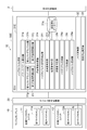
- FIG. 1 is a configuration diagram of an approaching vehicle detection device according to the first embodiment.
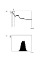
- FIG. 2 is an example of data in a time zone in which traveling sound is observed, where (a) is a power spectrum and (b) is a histogram of the power spectrum.
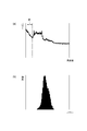
- FIG. 3 is an example of data in a time zone in which no running sound is observed.
- (A) is a power spectrum, and (b) is a histogram of the power spectrum.
- FIG. 4 is an example of a time change of the scale parameter.
- the approaching vehicle detection device 1A determines whether or not the sound signal collected by the microphone includes a sound source to be detected (vehicle running sound) in order to determine timing suitable for noise model generation, and noise The timing (section) at which the model can be generated is determined. For this purpose, the approaching vehicle detection device 1A calculates the power spectrum of the sound signal and evaluates the power spectrum histogram (probability density distribution) by gamma distribution fitting.
- FIG. 2A shows the power spectrum (power (energy) for each frequency) of a sound signal when the sound signal includes a running sound.
- FIG. 3A shows the running signal in the sound signal. The power spectrum of the sound signal when no is included is shown.
- the section indicated by symbol R is a frequency band in which the sound component of the running sound appears dominantly.
- FIG. 2B shows a histogram of the power spectrum (frequency of each power) in the frequency band R when the sound signal includes running sound
- FIG. 3A shows the sound signal. The histogram of the power spectrum in the frequency band R when the running sound is not included is shown.
- noise components for example, white noise, pink noise, etc.
- the power distribution is different between the case where only (noise) is included and the case where the sound information includes the traveling sound component of the vehicle in addition to the noise component.
- This difference is well understood from the difference in the shape of the histogram by comparing the histogram of the power spectrum in the frequency band R shown in FIG. 2B and the histogram of the power spectrum in the frequency band R shown in FIG. .
- the sound signal contains only the noise component or the traveling sound component to be detected in addition to the noise component in the sound signal Can be determined.
- the noise model in order to detect a running sound with high accuracy using a sound signal whose noise component is suppressed based on the noise model, it is necessary to generate a noise model from a sound signal collected in an environment where no running sound exists. There is.
- the noise model when a noise model is generated from a sound signal collected in an environment where traveling sound exists, the noise model also includes a traveling sound component. It suppresses even the component.
- FIG. 4 shows an example of the time change of the scale parameter obtained from the power spectrum of the sound signal collected while the vehicle is traveling on the solid line L1.
- the scale parameter is close to 0 in the time zone when no running sound is observed, but the scale parameter is significantly larger in the time zones T1, T2, T3, and T4 where the running sound is observed. Become. In this way, it is possible to discriminate between the environment where the running sound exists and the environment where the running sound does not exist from the magnitude of the scale parameter.
- the shape parameter of the gamma distribution is obtained using gamma distribution fitting, the scale parameter is obtained from the shape coefficient, and the scale parameter is obtained.
- the gamma distribution is a kind of continuous probability distribution, and its characteristics are characterized by two parameters, a shape distribution and a scale distribution.
- the shape parameter and scale parameter can be obtained directly from the power spectrum, so the histogram of the power spectrum may be calculated and the gamma distribution fitting may be performed, or the histogram may be calculated. Alternatively, gamma distribution fitting may be performed.
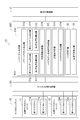
- the approaching vehicle detection device 1A includes a microphone array 10, a digital signal converter 20, and an ECU [Electronic Control Unit] 30A (a noise model generation unit 31A, a noise suppressor 32, and a sound source direction estimator 33).
- the microphone array 10 has a left microphone unit 11 and a right microphone unit 12.
- the left microphone unit 11 and the right microphone unit 12 are arranged on the left and right sides in the vehicle width direction (left-right direction) at the same height position at the front end of the vehicle.
- the left microphone unit 11 includes a first microphone 11a and a second microphone 11b.
- the first microphone 11a is disposed outside the left side in the vehicle width direction
- the second microphone 11b is disposed on the vehicle center side with a predetermined distance from the first microphone 11b.
- the right microphone unit 12 includes a third microphone 12a and a fourth microphone 12b.
- the fourth microphone 12b is disposed outside the right side in the vehicle width direction, and the third microphone 12a is disposed on the vehicle center side at a predetermined interval from the fourth microphone 12b.
- Each of the microphones 11 a, 11 b, 12 a, and 12 b is an acoustoelectric converter that converts a sound outside the vehicle into an analog electric signal and outputs the electric signal (sound signal) to the digital signal converter 20.
- the microphones 11a, 11b, 12a, and 12b correspond to the sound collectors described in the claims.
- each sound signal is converted into a digital sound signal (electric signal).
- the digital signal converter 20 outputs a digital sound signal (electric signal) for each microphone to the ECU 30A.
- the ECU 30A is an electronic control unit including a CPU [Central Processing Unit], ROM [Read Only Memory], RAM [Random Access Memory], and the like, and comprehensively controls the approaching vehicle detection device 1A.
- the ECU 30A includes a noise model generation unit 31A (power spectrum calculator 31a, histogram calculator 31b, scale parameter calculator 31c, noise model generation availability determination unit 31d, noise model generator 31e), noise suppressor 32, sound source direction.
- An estimator 33 is configured.
- a sound signal (digital electric signal) for each microphone is input from the digital signal converter 20.
- the power spectrum calculator 31a corresponds to the power spectrum acquisition unit described in the claims
- the scale parameter calculator 31c corresponds to the scale parameter calculation unit described in the claims.
- the noise model generation availability determination unit 31d corresponds to the determination unit described in the claims
- the noise model generator 31e corresponds to the noise model generation unit described in the claims
- the noise suppressor 32 corresponds to the claims. This corresponds to the noise suppression unit described in (1).
- the power spectrum calculator 31a performs an FFT [Fast Fourier Transform] (fast Fourier transform) on the sound signal using the digital sound signal from the digital signal converter 20, and the power spectrum of the sound signal (for each frequency). Power (energy) is calculated.
- FFT Fast Fourier Transform
- the sound signal of any one of the sound signals of the four microphones 11a, 11b, 12a, and 12b may be used, or the sound signals of the four microphones 11a, 11b, 12a, and 12b may be used.
- a sound signal obtained by averaging sound signals of a plurality of microphones for example, two microphones corresponding to the left side and the right side, and all four microphones may be used.
- the histogram calculator 31b calculates a histogram of the power spectrum in the frequency band in which the running sound is dominantly included from the power spectrum calculated by the power spectrum calculator 31a.
- the scale parameter calculator 31c performs gamma distribution fitting using the power spectrum data in the frequency band in which the running sound is predominantly included, and calculates the scale parameter.
- the estimated value of the shape parameter ⁇ is calculated by the equation (1).
- ⁇ in Expression (1) can be calculated by Expression (2) using a power data sequence ⁇ x: x1, x2,..., XN ⁇ of each frequency in a frequency band in which traveling sound is dominant.
- the estimated value of the shape parameter ⁇ and the data string ⁇ x: x1, x2,..., XN ⁇ is calculated by Equation (3).
- the scale parameter calculated by the scale parameter calculator 31c is compared with a threshold value.
- the threshold value is a threshold value for determining whether or not a running sound is included in the sound signal based on the magnitude of the scale parameter, and is set in advance by an experiment or the like.
- the noise model generator 31e generates a noise model using the digital sound signal from the digital signal converter 20 when the noise model generation availability determination unit 31d determines that the noise model can be generated.
- this generation method a conventional method is applied.
- the sound signal of any one of the four microphones 11a, 11b, 12a, and 12b is directly used as a noise model, or four A sound signal obtained by averaging sound signals of a plurality of microphones among sound signals of the microphones 11a, 11b, 12a, and 12b is used as a noise model.
- the noise suppressor 32 suppresses noise components from the digital sound signal for each microphone from the digital signal converter 20 using a noise model.
- a conventional method is applied. For example, a section having a larger value than the noise model is extracted from the sound signal, and only the sound signal in the section is used by the sound source direction estimator 33.
- the noise model is already generated by the noise model generator 31e.
- the noise model is used.
- a noise model prepared in advance is used. Use. The noise model prepared in advance is generated in advance by experiments or the like.
- the sound source direction estimator 33 uses the sound signals of the microphones 11a, 11b, 12a, and 12b whose noise components are suppressed by the noise suppressor 32 to detect the sound source to be detected (running sound (and thus a vehicle approaching the host vehicle)). ) Is present, and if a sound source is present, the direction and distance of the sound source are estimated.
- a conventional method is applied, for example, CSP [Cross power Spectrum Phase analysis] method.
- CSP Cross-correlation value
- the cross-correlation value is equal to or greater than a threshold, a sound source exists. If the sound source is present, the direction, distance, etc. of the vehicle are obtained from the arrival time difference that maximizes the cross-correlation value.
- the ECU 30A generates approaching vehicle information based on the detection result of the sound source to be detected by the sound source direction estimator 33, and outputs the approaching vehicle information to the driving support device 2.
- the approaching vehicle information includes, for example, the presence / absence of an approaching vehicle, and information on a direction and a distance when an approaching vehicle exists.
- the driving support device 2 is a device that supports various driving operations for the driver.
- driving assistance device 2 when approaching vehicle information is input from the approaching vehicle detection device 1A at regular intervals, driving assistance regarding the approaching vehicle is performed. For example, if there is a vehicle approaching the host vehicle, determine the possibility of a collision of the approaching vehicle to the host vehicle, and output a warning to the driver when it is determined that there is a possibility of a collision, Information on approaching vehicles is provided, and when the possibility of collision increases, vehicle control such as automatic braking and automatic steering is performed.
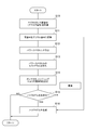
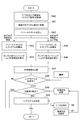
- FIG. 5 is a flowchart showing an overall operation flow in the approaching vehicle detection device according to the present embodiment.
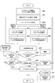
- FIG. 6 is a flowchart showing a flow of operations related to noise model generation according to the first embodiment.
- the system operation logic of the approaching vehicle detection device 1A is determined (S1), and it is determined whether or not the approaching vehicle detection device 1A is to be operated (S2).
- This system operation logic is a condition for determining whether or not the approaching vehicle detection device 1A needs to be operated.
- the vehicle condition is that the vehicle speed is equal to or higher than a predetermined vehicle speed
- the traffic environment is There is a condition that there is an intersection in front of the vehicle.
- the higher-level device that manages the approaching vehicle detection device 1A in an integrated manner, and it is determined that the higher-level device (particularly the ECU) performs the processes of S1 and S2 to activate the approaching vehicle detection device 1A.
- the approaching vehicle detection device 1A is activated.
- the approaching vehicle detection device 1A is operated. While the approaching vehicle detection device 1A is operating, the following operations are repeated.
- the approaching vehicle detection device 1A ambient sounds outside the vehicle are collected by the microphones 11a, 11b, 12a, and 12b of the microphone array 10, and the sound signals of the microphones 11a, 11b, 12a, and 12b are converted into digital signal converters. 20 to convert each into a digital signal.
- the ECU 30A noise model generation unit 31A of the approaching vehicle detection device 1A uses the sound signal converted by the digital signal converter 20 to determine whether or not a running sound as a detection target exists in the sound signal.
- the ECU 30A of the approaching vehicle detection device 1A generates a noise model using a sound signal when it is determined in S4 that a noise model can be generated (S5). If it is determined in S4 that a noise model cannot be generated, no noise model is generated.
- S3 to S5 The operations of S3 to S5 will be described later in detail.
- the ECU 30A noise suppressor 32 of the approaching vehicle detection device 1A
- the sound of each microphone converted by the digital signal converter 20 using the noise model is used.
- Each noise component is suppressed from the signal (S6).
- the noise component is suppressed from the sound signal of each microphone converted by the digital signal converter 20 using a noise model prepared in advance (S6). More specifically, in the case where there is no noise model, the generation of the noise model is executed between the predetermined time and the current time, in addition to the case where the generation of the noise model has never been executed. This is the case when there is no such thing.
- the ECU 30A uses the sound signal of each microphone whose noise component is suppressed in S6 to determine whether there is a sound source to be detected (a running sound of a vehicle approaching the host vehicle). If there is a sound source to be detected, the direction and distance of the sound source to be detected is estimated (S7). Then, the ECU 30A generates approaching vehicle information based on the detection result of the sound source, and outputs the approaching vehicle information to the driving support device 2.
- S6 when a noise model has not yet been generated, noise suppression is performed using a prepared noise model. However, when a noise model has not yet been generated, noise suppression is not performed. It is good also as a structure which determines whether the sound source of a detection target exists.
- Each microphone 11a, 11b, 12a, 12b of the microphone array 10 collects sounds outside the vehicle and acquires an analog sound signal (S10).
- the digital signal converter 20 converts the analog sound signals of the microphones 11a, 11b, 12a, and 12b into digital sound signals, respectively (S11).
- ECU 30A power spectrum calculator 31a
- the ECU 30A performs FFT on the sound signal converted into the digital signal in S11 to calculate the power spectrum of the sound signal (S12).
- the ECU 30A calculates a histogram of the power spectrum in the frequency band where the running sound is dominant from the power spectrum (S13).
- the ECU 30A scale parameter calculator 31c
- the ECU 30A (noise model generation availability determination unit 31d) compares the scale parameter with a threshold value to determine whether noise model generation is possible (S15). If the scale parameter is greater than or equal to the threshold value in S15, it is determined that the noise model cannot be generated, and no noise model is generated. On the other hand, if the scale parameter is less than the threshold value in S15, it is determined that a noise model can be generated, and the ECU 30A (noise model generator 31e) generates a noise model using the sound signal converted into a digital signal in S11. (S16).
- this approaching vehicle detection device 1A by evaluating the histogram of the power spectrum of the sound signal, it can be determined with high accuracy whether or not a running sound (sound source to be detected) is included in the sound signal. Appropriate timing for generating a noise model can be determined, and a noise model can be generated adaptively for each environment. By using the generated noise model, the noise component suppression effect from the sound signal is improved. By using the sound signal in which the noise component is suppressed, the approaching vehicle can be detected with high accuracy. Furthermore, according to the approaching vehicle detection device 1A, the histogram of the power spectrum can be evaluated with high accuracy by using the scale parameter by gamma distribution fitting.
- FIG. 7 is a configuration diagram of the approaching vehicle detection device according to the second embodiment.
- FIG. 8 is an example of the time variation of the scale parameter in the frequency band where the running sound is observed and the scale parameter in the frequency band where the running sound is not observed.
- the approaching vehicle detection device 1B includes traveling sound in the sound signal collected by the microphone from the characteristics of the two frequency bands in the collected sound signal. It has a function of determining whether or not Therefore, the approaching vehicle detection device 1B calculates the power spectrum of the sound signal, the histogram of the power spectrum of the first frequency band including the traveling sound (sound source to be detected), and the second frequency band not including the traveling sound. The power spectrum histogram is evaluated by gamma distribution fitting.
- the scale parameter of the first frequency band including the traveling sound (the sound source to be detected) and the traveling sound are not included.
- the relationship with the scale parameter of the two frequency bands will be described.
- a noise environment such as white noise or pink noise is generated, and thus the power distribution is continuous in the entire frequency band.
- the power distribution changes in the frequency band including the traveling sound, so that there is no continuity between the frequency band including the traveling sound and the other frequency bands. Therefore, by comparing the histograms of the power spectra of the two frequency bands, an environment where no running sound exists (an environment suitable for generating a noise model) or an environment where running noise exists (a noise model is generated). Can be determined with high accuracy.
- FIG. 8 shows an example of the temporal change of the scale parameter obtained from the power spectrum of the frequency band including the traveling sound in the sound signal collected during traveling of the vehicle on the solid line L2, and the traveling sound on the same sound signal on the solid line L3.
- 3 shows an example of a time change of a scale parameter obtained from a power spectrum in a frequency band that does not include.
- the scale parameter is close to 0 in the time zone in which the running sound is not observed, and the scale parameter is significantly increased in the time zone in which the running sound is observed. .
- the scale parameter is close to 0 not only in the time zone in which the traveling sound is not observed but also in the time zone in which the traveling sound is observed.
- the environment where the traveling sound exists and the environment where the traveling sound does not exist can be distinguished. .
- the gamma distribution is evaluated.
- the shape parameter of the gamma distribution in the first frequency band and the shape parameter of the gamma distribution in the second frequency band are obtained, and the scale parameter of the gamma distribution in the first frequency band and the second are obtained from the respective shape factors.
- a scale parameter of the gamma distribution in the frequency band is obtained, and two scale parameters (particularly, a difference or ratio between the two scale parameters) are used as evaluation feature amounts.
- the first frequency band (frequency band in which the traveling sound is dominant)
- a band including the frequency band of the traveling sound of the vehicle measured in advance by an actual vehicle experiment or the like is set.
- a band other than the first frequency band is set within the frequency band that can be detected by the microphone.
- the maximum frequency in the first frequency band can be detected by the microphone.
- a band up to a frequency that is a predetermined amount smaller than the upper limit frequency is set.
- the approaching vehicle detection device 1B includes a microphone array 10, a digital signal converter 20, and an ECU 30B (a noise model generation unit 31B, a noise suppressor 32, and a sound source direction estimator 33).
- ECU30B especially noise model production
- the ECU 30B is an electronic control unit including a CPU, a ROM, a RAM, and the like, and comprehensively controls the approaching vehicle detection device 1B.
- the ECU 30B includes a noise model generation unit 31B (power spectrum calculator 31a, first histogram calculator 31g, second histogram calculator 31h, first scale parameter calculator 31i, second scale parameter calculator 31j, scale parameter).
- a number comparator 31k, a noise model generation availability determination unit 31l, a noise model generator 31e), a noise suppressor 32, and a sound source direction estimator 33 are configured.
- a sound signal digital electric signal
- the power spectrum calculator 31a, the noise model generator 31e, the noise suppressor 32, and the sound source direction estimator 33 have already been described, description thereof will be omitted.
- the power spectrum calculator 31a corresponds to the power spectrum acquisition unit described in the claims
- the first scale parameter calculator 31i and the second scale parameter calculator 31j The scale parameter calculator 31k and the noise model generation availability determination unit 31l correspond to the determination unit described in the claims
- the noise model generator 31e corresponds to the claims.
- the noise suppressor 32 corresponds to a noise suppressor described in the claims.
- the first histogram calculator 31g calculates a power spectrum histogram in the first frequency band in which the running sound is dominant from the power spectrum calculated by the power spectrum calculator 31a.
- the second histogram calculator 31h calculates a histogram of the power spectrum in the second frequency band where the running sound is not dominant from the power spectrum calculated by the power spectrum calculator 31a.
- the first scale parameter calculator 31i performs gamma distribution fitting using the data of the power spectrum in the first frequency band where the running sound is dominant, and calculates the scale parameter of the first frequency band where the running sound is dominant. calculate. Further, the second scale parameter calculator 31j performs gamma distribution fitting using the data of the power spectrum in the second frequency band where the running sound is not dominant, and the scale base of the second frequency band where the running sound is not dominant. Calculate the number.
- the scale parameter comparator 31k subtracts the scale parameter of the second frequency band calculated by the second scale parameter calculator 31j from the scale parameter of the first frequency band calculated by the first scale parameter calculator 31i. The difference between the two scale parameters is calculated.
- the noise model generation feasibility determiner 31l compares the scale parameter difference calculated by the scale parameter comparator 31k with a threshold value, and if the scale parameter difference is equal to or greater than the threshold value (the scale parameter of the first frequency band is When it becomes large and there is a clear difference between the scale parameters of the two frequency bands, and it can be determined that the sound signal contains running sound), it is determined that the noise model cannot be generated, and the scale parameter is less than the threshold. In the case of (if it is determined that there is no clear difference between the scale parameters of the two frequency bands and the sound signal does not include running sound), it is determined that the noise model can be generated.
- This threshold is a threshold for determining whether or not a running sound is included in the sound signal based on the difference or ratio of the scale parameters of the two frequency bands, and is set in advance by an experiment or the like. .
- FIG. 9 is a flowchart showing a flow of operations related to noise model generation according to the second embodiment.
- the operations other than the operation related to the noise model generation in the approaching vehicle detection device 1B are the same as those in the approaching vehicle detection device 1A according to the first embodiment, and thus the description thereof is omitted.
- the ECU 30B calculates a histogram of the power spectrum in the first frequency band where the running sound is dominant from the power spectrum (S23). Further, the ECU 30B (first scale parameter calculator 31i) performs gamma distribution fitting using the power spectrum data in the first frequency band where the running sound is dominant, and calculates the scale parameter of the first frequency band. (S24). Further, the ECU 30B (second histogram calculator 31h) calculates a histogram of the power spectrum in the second frequency band where the running sound is not dominant from the power spectrum (S25). Further, the ECU 30B (second scale parameter calculator 31j) performs gamma distribution fitting using the power spectrum data in the second frequency band where the running sound is not dominant, and calculates the scale parameter of the second frequency band. (S26).
- the ECU 30B calculates the difference between the scale parameter of the first frequency band calculated in S24 and the scale parameter of the second frequency band calculated in S26 (S27). Then, the ECU 30B (noise model generation availability determination unit 31l) compares the scale parameter difference with a threshold value to determine whether noise model generation is possible (S28). If the difference in the scale parameter is equal to or larger than the threshold value in S28, it is determined that the noise model cannot be generated, and the noise model is not generated.
- the ECU 30B uses the sound signal converted into the digital signal in S21 to use the noise model. Is generated (S29).
- the approaching vehicle detection device 1B has the same effects as the approaching vehicle detection device 1A according to the first embodiment, and also has the following effects. According to the approaching vehicle detection device 1B, by comparing and evaluating the histogram of the power spectrum in the first frequency band that includes the traveling sound and the histogram of the power spectrum in the second frequency band that does not include the traveling sound, Can detect with high accuracy whether or not it contains a running sound, can determine the appropriate timing for generating a noise model, and can generate a noise model following the fluctuation of the environment Can do.
- FIG. 10 is a configuration diagram of the approaching vehicle detection device according to the third embodiment.
- the difference in the scale parameter between the first frequency band and the second frequency band is small (determined that the noise model can be generated).
- the noise model can be generated.
- a point sound source exists, it has a function of not generating a noise model.
- the point sound source is a specific sound source that is not environmental noise such as white noise or pink noise.
- the sound source to be detected is a running sound of the vehicle (one of the point sound sources), and the sound source detected by the sound source direction estimator 33 is highly likely to be a running sound of the vehicle.
- the sound source direction estimator 33 detects the sound source to be detected, but the difference in the scale parameter between the first frequency band and the second frequency band is still small (the sound source to be detected is far away from the host vehicle). Etc.). In such a case, depending on the setting of the threshold value, it may be determined that the noise model can be generated by determining the difference in the scale parameter, but the sound signal may include a traveling sound component.
- the third embodiment using the detection result of the sound source to be detected by the sound source direction estimator 33, it is determined whether or not a point sound source exists in the sound signal, and the point sound source exists. In this case, noise model generation is not performed.
- the approaching vehicle detection device 1C includes a microphone array 10, a digital signal converter 20, and an ECU 30C (a noise model generation unit 31C, a noise suppressor 32, and a sound source direction estimator 33).
- ECU30C especially noise model production
- the ECU 30C is an electronic control unit including a CPU, a ROM, a RAM, and the like, and comprehensively controls the approaching vehicle detection device 1C.
- the ECU 30C includes a noise model generation unit 31C (power spectrum calculator 31a, first histogram calculator 31g, second histogram calculator 31h, first scale parameter calculator 31i, second scale parameter calculator 31j, scale parameter).
- a sound signal digital electric signal
- the digital signal converter 20 is input from the digital signal converter 20.
- a power spectrum calculator 31a a power spectrum calculator 31a, a first histogram calculator 31g, a second histogram calculator 31h, a first scale parameter calculator 31i, a second scale parameter calculator 31j, a scale parameter comparator 31k, a noise model Since the generation possibility determination unit 31l, the noise model generator 31e, the noise suppressor 32, and the sound source direction estimator 33 have already been described, description thereof will be omitted.
- the power spectrum calculator 31a corresponds to the power spectrum acquisition unit described in the claims
- the first scale parameter calculator 31i and the second scale parameter calculator 31j The scale parameter comparator 31k and the noise model generation possibility determination unit 31l correspond to the determination unit described in the claims
- the sound source direction estimator 33 and the point sound source determination unit correspond to the scale parameter calculation unit described in the range.
- 31n corresponds to the point sound source detector described in the claims
- the noise model generator 31e corresponds to the noise model generator described in the claims
- the noise suppressor 32 describes the noise suppressor described in the claims It corresponds to.
- the noise model generation enable / disable determination unit 31l determines that the noise model can be generated, based on the detection result of the detection target sound source in the sound source direction estimator 33, It is determined whether or not a sound source exists.
- the noise model generator 31e does not generate a noise model when the point sound source determination unit 31n determines that a point sound source exists even when the noise model generation possibility determination unit 31l determines that the noise model can be generated. .
- FIG. 11 is a flowchart showing a flow of operations related to noise model generation according to the third embodiment.
- the operations other than the operation related to the noise model generation in the approaching vehicle detection device 1C are the same as those in the approaching vehicle detection device 1A according to the first embodiment, and thus the description thereof is omitted.
- the noise model generated in S50 is used (if a noise model is not generated, a noise model prepared in advance is used), S41.
- the noise component is suppressed from the sound signal of each microphone converted into a digital signal in step S6.
- the ECU 30C uses the sound signal of each microphone whose noise component is suppressed in S6 to determine whether there is a sound source to be detected (a running sound of a vehicle approaching the host vehicle). If there is a sound source to be detected, the direction and distance of the sound source to be detected is estimated (S7).
- the ECU 30C determines whether or not a point sound source is detected based on the detection result of the sound source to be detected in S7 (S49). . If it is determined in S49 that a point sound source has been detected, no noise model is generated. On the other hand, when it is determined in S49 that the point sound source is not detected, the ECU 30C (noise model generator 31e) generates a noise model using the sound signal converted into the digital signal in S41 (S50).
- the approaching vehicle detection device 1C has the same effects as the approaching vehicle detection device 1B according to the second embodiment, and also has the following effects. According to the approaching vehicle detection device 1C, even when the difference between the first frequency band and the second frequency band and the scale parameter is small and it is determined that the noise model can be generated, noise model generation is determined in consideration of the presence or absence of a point sound source. By doing so, the appropriate timing for generating the noise model can be determined with higher accuracy.
- FIG. 12 is a configuration diagram of the approaching vehicle detection device according to the fourth embodiment.
- the approaching vehicle detection device 1D has a function of generating a noise model when there is an interference sound (characteristic sound) other than the sound source to be detected. is doing.
- the interfering sound is a characteristic sound source other than the sound source to be detected among specific sound sources (point sound sources) that are not environmental noises such as white noise and pink noise.
- the sound source direction estimator 33 detects the sound source to be detected (running sound). If there is a characteristic sound source having a frequency band overlapping with the running sound in a certain environment, the sound source direction estimator 33 detects the sound source.
- the sound source may be a sound source other than the running sound. Such a sound source other than the running sound corresponds to a noise component.
- interference sounds other than the sound source to be detected are detected, it is determined whether or not there is an interference sound in the sound signal, and if there is an interference sound, a noise model is detected. Generate.
- the approaching vehicle detection device 1D includes a microphone array 10, a digital signal converter 20, and an ECU 30D (noise model generation unit 31D, noise suppressor 32, and sound source direction estimator 33).
- ECU30D especially noise model production
- the ECU 30D is an electronic control unit including a CPU, a ROM, a RAM, and the like, and comprehensively controls the approaching vehicle detection device 1D.
- the ECU 30D includes a noise model generation unit 31D (power spectrum calculator 31a, first histogram calculator 31g, second histogram calculator 31h, first scale parameter calculator 31i, second scale parameter calculator 31j, scale parameter).
- An estimator 33 is configured.
- a sound signal (digital electric signal) for each microphone is input from the digital signal converter 20.
- a power spectrum calculator 31a a power spectrum calculator 31a, a first histogram calculator 31g, a second histogram calculator 31h, a first scale parameter calculator 31i, a second scale parameter calculator 31j, a scale parameter comparator 31k, a noise model Since the generation possibility determination unit 31l, the point sound source determination unit 31n, the noise model generation unit 31e, the noise suppressor 32, and the sound source direction estimation unit 33 have already been described, description thereof will be omitted.
- the power spectrum calculator 31a corresponds to the power spectrum acquisition unit described in the claims
- the first scale parameter calculator 31i and the second scale parameter calculator 31j The scale parameter comparator 31k and the noise model generation possibility determination unit 31l correspond to the determination unit described in the claims
- the sound source direction estimator 33 and the point sound source determination unit correspond to the scale parameter calculation unit described in the range.
- 31n corresponds to the point sound source detector described in the claims
- the interference sound detector 31p, the timbre characteristic database 31q, and the interference sound determiner 31r correspond to the characteristic sound detector described in the claims
- the device 31e corresponds to the noise model generation unit described in the claims
- the noise suppressor 32 corresponds to the noise suppression unit described in the claims.
- the interfering sound detector 31p uses the digital sound signal from the digital signal converter 20 to detect a characteristic sound source (interfering sound) other than the sound source to be detected.
- a characteristic sound source interfering sound
- this detection method for example, when the timbre characteristic database 31q is provided, spectrum pattern recognition is performed between each sound source other than the detection target sound source stored in the timbre characteristic database 31q and the sound signal, and the It is determined whether or not there is a sound source (interference sound) other than the sound source to be detected.
- each sound source for example, sound generated at each store, sound generated at a vending machine, vehicle engine sound, A spectrum pattern of a crossing warning sound generated at a crossing and noise caused by an airplane or a train around an airport or a station is stored.
- the sound signal has a harmonic structure (a structure having periodicity in frequency) by LPC [Linear Predictive Coding] or the like, and a sound having a harmonic structure is detected. It is detected as a sound source (interference sound) other than the sound source.
- the vehicle running sound has power distributed over the entire frequency band and does not have a harmonic structure.
- the interference sound detector 31p Based on the detection result, it is determined whether or not a disturbing sound exists.
- the noise model generator 31e when the noise model generation availability determination unit 31l determines that the noise model can be generated and the point sound source determination unit 31n determines that a point sound source exists, or the noise model generation availability determination unit 31l. Even when it is determined that the noise model cannot be generated, the noise model is generated when the interference sound determination unit 31r determines that the interference sound (sound source other than the detection target sound source) exists.
- FIG. 13 is a flowchart showing a flow of operations related to noise model generation according to the fourth embodiment.
- the operations other than the operation relating to the noise model generation in the approaching vehicle detection device 1D are the same as those of the approaching vehicle detection device 1A according to the first embodiment, and thus the description thereof is omitted.
- the ECU 30D (interference sound detector 31p) of the approaching vehicle detection device 1D uses the sound signal converted into the digital signal in S61 to detect interference sound other than the sound source to be detected in the sound signal (S70). .
- spectral pattern recognition is performed using the spectrum pattern of each sound source stored in the database 31q, and when there is no timbre characteristic database 31q, a sound having a harmonic structure is obtained. And so on.
- the ECU 30D determines the interference sound in S70. Based on the detection result, it is determined whether or not an interfering sound is detected (S71). If it is determined in S71 that no disturbing sound has been detected, no noise model is generated. On the other hand, when it is determined in S71 that the interference sound is detected, the ECU 30C (noise model generator 31e) generates a noise model using the sound signal converted into the digital signal in S61 (S72).
- the approaching vehicle detection device 1D has the same effects as the approaching vehicle detection device 1C according to the third embodiment, and also has the following effects. According to the approaching vehicle detection device 1D, even when it is determined that a point sound source is present or when the difference between the first frequency band and the second frequency band and the scale parameter is large, it is determined that the noise model cannot be generated. By determining the noise model generation in consideration of the presence or absence of the noise, it is possible to determine the appropriate timing for generating the noise model with higher accuracy.
- FIG. 14 is a configuration diagram of an approaching vehicle detection device according to the fifth embodiment.
- the approaching vehicle detection device 1E has a function of updating the noise model according to a change in environment when the noise model has already been generated. Yes.
- the noise model Even after the noise model is generated, if the surrounding environment changes while the vehicle is running, the noise component may change depending on the environment. In order to cope with such a change in the environment, if a noise model is regenerated from the sound signal acquired in each environment each time, the processing load increases. In addition, when changing the noise model from scratch, for example, if a noise model is generated when an instantaneous characteristic sound is generated in a certain environment, it becomes a discontinuous noise model. If noise suppression is performed in this process, the suppression effect is reduced.
- the generated noise model is compared with a sound signal (power spectrum) acquired in the current environment. If there is a change, the noise model is updated in consideration of the sound signal (power spectrum) in the current environment.
- the approaching vehicle detection device 1E includes a microphone array 10, a digital signal converter 20, and an ECU 30E (a noise model generation unit 31E, a noise suppressor 32, and a sound source direction estimator 33).
- ECU30E especially noise model production
- the ECU 30E is an electronic control unit including a CPU, a ROM, a RAM, and the like, and comprehensively controls the approaching vehicle detection device 1E.
- the ECU 30E includes a noise model generation unit 31E (power spectrum calculator 31a, first histogram calculator 31g, second histogram calculator 31h, first scale parameter calculator 31i, second scale parameter calculator 31j, scale parameter).
- a sound signal (digital electric signal) for each microphone is input from the digital signal converter 20.
- a power spectrum calculator 31a a power spectrum calculator 31a, a first histogram calculator 31g, a second histogram calculator 31h, a first scale parameter calculator 31i, a second scale parameter calculator 31j, a scale parameter comparator 31k, a noise model
- the generation possibility determination unit 31l, the point sound source determination unit 31n, the interference sound detector 31p, the timbre characteristic database 31q, the interference sound determination unit 31r, the noise model generator 31e, the noise suppressor 32, and the sound source direction estimator 33 have already been described. Therefore, the description is omitted.
- the power spectrum calculator 31a corresponds to the power spectrum acquisition unit described in the claims
- the first scale parameter calculator 31i and the second scale parameter calculator 31j The scale parameter comparator 31k and the noise model generation possibility determination unit 31l correspond to the determination unit described in the claims
- the sound source direction estimator 33 and the point sound source determination unit correspond to the scale parameter calculation unit described in the range.
- the interference sound detector 31p, the timbre characteristic database 31q, and the interference sound determiner 31r correspond to the characteristic sound detector described in the claims
- the device 31e corresponds to the noise model generation unit described in the claims
- the noise model updater 31u corresponds to the noise model update unit described in the claims
- the noise suppressor 32 includes Corresponding to the noise suppressing unit described in the scope of seeking.
- the noise comparator 31t if a noise model has already been generated in the process up to the previous time, the noise model is compared with the sound signal (power spectrum) acquired in the current environment, and whether the noise model has changed from the noise model. Determine whether or not.
- the noise model updater 31u when it is determined that the noise comparator 31t has changed using a first-order IIR [Infinite Impulse Response] filter, the sound signal (power spectrum) acquired in the current environment in the noise model ) To update the noise model. Specifically, using the power spectrum A ( ⁇ ) of the sound signal in the current environment and the noise model N ( ⁇ ) n before update, the noise model N ( ⁇ ) n + 1 after update according to the equation (4). Is calculated.
- ⁇ is a forgetting factor and indicates the degree to which the power spectrum of the sound signal in the current environment is added.
- the forgetting factor is a value between 0 and 1, may be a fixed value, or may be a variable value considering the degree of change from the noise model.
- the noise model may be updated by a method other than the method using the primary IIR filter.
- the noise model generation availability determination unit 31l, the point sound source determination unit 31n, and the interference sound determination unit 31r are in a condition that noise model generation is not possible (when a detection target sound source exists)
- the noise model Since the sound source component to be detected is added to the noise model when updating, it is preferable not to update the noise model.
- FIG. 15 is a flowchart showing a flow of operations related to noise model generation according to the fifth embodiment.
- the operations other than the operation related to the noise model generation in the approaching vehicle detection device 1E are the same as those in the approaching vehicle detection device 1A according to the first embodiment, and thus the description thereof is omitted.
- S80 to S82, S84 to S93, and S6 and S7 in the approaching vehicle detection device 1E are the same as those of S60 to S62, S63 to S72, S6, and S7 in the approaching vehicle detection device 1D according to the fourth embodiment. Therefore, explanation is omitted.
- the ECU 30E determines whether there is no noise model generated until the previous time (S83). If it is determined in S83 that there is no noise model generated up to the previous time, the processing after S84 is performed.
- the ECU 30E (noise comparator 31t) compares the power spectrum of the current sound signal with the noise model, and whether there is a change from the noise model. Is determined (S94). When there is a change from the noise model, the ECU 30E (noise model updater 31u) updates the noise model by adding the power spectrum of the current sound signal to the noise model by the primary IIR filter (S95).
- the approaching vehicle detection device 1E has the same effects as the approaching vehicle detection device 1D according to the fourth embodiment, and also has the following effects. According to the approaching vehicle detection device 1E, when a noise model has already been generated, the noise model is updated by taking into account the sound signal collected in the current environment, thereby reducing the environmental load with a small processing load. An appropriate noise model corresponding to the change can be generated.
- the sound source azimuth estimation device is mounted on a vehicle and applied to an approaching vehicle detection device that detects an approaching vehicle (vehicle running sound as a sound source), but may be a device that detects a sound source other than the vehicle.
- a sound source azimuth estimation apparatus mounted on a moving body other than a vehicle may be used.
- the detected approaching vehicle information is applied to a device that provides the driving support device to the driving support device.
- the present invention may be applied to a noise model generation device that generates a noise model from sound information collected by a microphone.
- the present invention may be applied to a noise suppression device that generates a noise model and performs noise suppression from sound information collected by a microphone using the noise model.
- a histogram of the power spectrum of sound is calculated, a scale parameter is calculated by gamma distribution fitting, and it is determined whether or not a noise model can be generated based on the scale parameter.
- a noise model is generated, but the present invention is applied to a sound source detection device (for example, an approaching vehicle detection device) that detects a sound source to be detected (for example, a running sound of an approaching vehicle) based on the scale parameter. Also good.
- the timing (section) when the noise model cannot be generated described in the present embodiment is the timing (section) at which the traveling sound (the presence of an approaching vehicle exists) can be detected.
- a microphone array including four microphones and left and right microphone units has been described as an example.
- various other variations are applicable to the number and arrangement of microphones (sound collectors). Is possible. Incidentally, only one microphone may be used.
- the power spectrum histogram is calculated and the scale parameter is calculated by gamma distribution fitting.
- the histogram is not calculated (the histogram calculator A configuration in which the scale parameter is calculated by gamma distribution fitting using the power spectrum directly.
- the gamma distribution is used to evaluate the power spectrum histogram.
- the power spectrum histogram may be evaluated by other evaluation methods. For example, normal distribution, Laplace distribution, and binomial distribution are used.
- the scale parameter of the gamma distribution is used to determine whether or not a noise model can be generated. However, whether or not a noise model can be generated may be determined using other feature quantities.
- the present invention relates to a sound source detection device that detects a sound source to be detected from sound information collected by a sound collector, and a noise model related to noise information other than the sound source to be detected included in the sound information collected by the sound collector
- the present invention can be used in a noise model generation device that generates noise, a noise suppression device that uses the noise model, a sound source direction estimation device, an approaching vehicle detection device, and a noise suppression method.
- Second histogram calculator 31i: first scale parameter calculator, 31j: second scale parameter calculation 31k: Scale parameter comparator, 31n: Point sound source determination unit, 31p: Interference sound detector, 31q ... Tone characteristic database, 31r ... Interference sound determination unit, 31t ... Noise comparator, 31u ... Noise model updater, 32 ... Noise suppressor, 33 ... Sound source direction estimator.
Landscapes
- Engineering & Computer Science (AREA)
- Physics & Mathematics (AREA)
- Acoustics & Sound (AREA)
- Multimedia (AREA)
- Health & Medical Sciences (AREA)
- Signal Processing (AREA)
- Audiology, Speech & Language Pathology (AREA)
- Human Computer Interaction (AREA)
- Computational Linguistics (AREA)
- Quality & Reliability (AREA)
- General Health & Medical Sciences (AREA)
- Otolaryngology (AREA)
- Measurement Of Mechanical Vibrations Or Ultrasonic Waves (AREA)
- Measurement Of Velocity Or Position Using Acoustic Or Ultrasonic Waves (AREA)
- Traffic Control Systems (AREA)
Abstract
Description
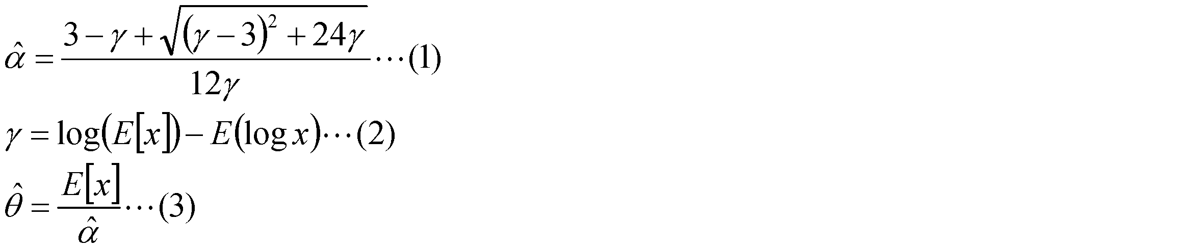

Claims (15)
- 集音器で集音された音情報から検出対象の音源を検出する音源検出装置であって、
前記集音器で集音された音情報からパワースペクトルを取得するパワースペクトル取得部と、
前記パワースペクトル取得部で取得したパワースペクトルの確率密度分布を評価することにより、前記集音器で集音された音情報の中に検出対象の音源が含まれているか否かを判定する判定部と、
を備えることを特徴とする音源検出装置。 - 前記判定部は、検出対象の音源に基づいて設定される第1周波数帯域でのパワースペクトルの確率密度分布と第1周波数帯域以外の第2周波数帯域でのパワースペクトルの確率密度分布とを評価することにより、前記集音器で集音された音情報の中に検出対象の音源が含まれているか否かを判定することを特徴とする請求項1に記載の音源検出装置。
- パワースペクトルに基づくガンマ分布フィッティングによりガンマ分布の尺度母数を算出する尺度母数算出部を備え、
前記判定部は、前記尺度母数算出部で算出した尺度母数を用いてパワースペクトルの確率密度分布を評価することを特徴とする請求項1又は請求項2に記載の音源検出装置。 - 集音器で集音された音情報に含まれる検出対象の音源以外のノイズ情報に関するノイズモデルを生成するためのノイズモデル生成装置であって、
前記集音器で集音された音情報からパワースペクトルを取得するパワースペクトル取得部と、
前記パワースペクトル取得部で取得したパワースペクトルの確率密度分布を評価することにより、前記集音器で集音された音情報の中に検出対象の音源が含まれているか否かを判定する判定部と、
前記判定部で音情報の中に検出対象の音源が含まれていないと判定している場合に前記集音器で集音された音情報からノイズモデルを生成するノイズモデル生成部と、
を備えることを特徴とするノイズモデル生成装置。 - 前記判定部は、検出対象の音源に基づいて設定される第1周波数帯域でのパワースペクトルの確率密度分布と第1周波数帯域以外の第2周波数帯域でのパワースペクトルの確率密度分布とを評価することにより、前記集音器で集音された音情報の中に検出対象の音源が含まれているか否かを判定することを特徴とする請求項4に記載のノイズモデル生成装置。
- パワースペクトルに基づくガンマ分布フィッティングによりガンマ分布の尺度母数を算出する尺度母数算出部を備え、
前記判定部は、前記尺度母数算出部で算出した尺度母数を用いてパワースペクトルの確率密度分布を評価することを特徴とする請求項4又は請求項5に記載のノイズモデル生成装置。 - 前記集音器で集音された音情報から点音源を検出する点音源検出部を備え、
前記ノイズモデル生成部は、前記判定部で音情報の中に検出対象の音源が含まれていないと判定している場合でも、前記点音源検出部で点音源を検出している場合にはノイズモデルを生成しないことを特徴とする請求項4~請求項6のいずれか1項に記載のノイズモデル生成装置。 - 前記集音器で集音された音情報から検出対象の音源以外の特徴音を検出する特徴音検出部を備え、
前記ノイズモデル生成部は、前記特徴音検出部で検出対象の音源以外の特徴音を検出している場合にはノイズモデルを生成することを特徴とする請求項4~請求項7のいずれか1項に記載のノイズモデル生成装置。 - 前記ノイズモデル生成部でノイズモデルを既に生成している場合、当該ノイズモデルを前記集音器で集音された音情報を加味して更新するノイズモデル更新部を備えることを特徴とする請求項4~請求項8のいずれか1項に記載のノイズモデル生成装置。
- 集音器で集音された音情報に含まれる検出対象の音源以外のノイズを抑圧するためのノイズ抑圧装置であって、
請求項4~請求項9のいずれか1項に記載のノイズモデル生成装置を備え、
前記ノイズモデル生成装置で生成したノイズモデルを用いて前記集音器で集音された音情報から検出対象の音源以外のノイズを抑圧することを特徴とするノイズ抑圧装置。 - 集音器で集音された音情報に含まれる検出対象の音源の方位を推定する音源方位推定装置であって、
請求項10に記載のノイズ抑圧装置を備え、
前記ノイズ抑圧装置でノイズが抑圧された音情報から検出対象の音源の方位を推定することを特徴とする音源方位推定装置。 - 車両に搭載される集音器で集音された音情報に基づいて接近する車両を検出する接近車両検出装置であって、
請求項11に記載の音源方位推定装置を備え、
前記音源方位推定装置で接近車両から発生する音源の方位を推定することを特徴とする接近車両検出装置。 - 集音器で集音された音情報に含まれる検出対象の音源以外のノイズを抑圧するためのノイズ抑圧装置であって、
前記集音器で集音された音情報の中に検出対象の音源が含まれているか否かを判定する判定部と、
前記判定部で音情報の中に検出対象の音源が含まれていないと判定している場合に前記集音器で集音された音情報からノイズモデルを生成するノイズモデル生成部と、
前記ノイズモデル生成部で生成したノイズモデルを用いて前記集音器で集音された音情報から検出対象の音源以外のノイズを抑圧するノイズ抑圧部と、
を備えることを特徴とするノイズ抑圧装置。 - 前記ノイズ抑圧部は、前記ノイズモデル生成部で生成したノイズモデルがある場合には前記ノイズモデル生成部で生成したノイズモデルを用いて前記集音器で集音された音情報から検出対象の音源以外のノイズを抑圧し、前記ノイズモデル生成部で生成したノイズモデルがない場合には予め用意されたノイズモデルを用いて前記集音器で集音された音情報から検出対象の音源以外のノイズを抑圧する又はノイズ抑圧をしないことを特徴とする請求項13に記載のノイズ抑圧装置。
- 集音器で集音された音情報に含まれる検出対象の音源以外のノイズを抑圧するためのノイズ抑圧方法であって、
前記集音器で集音された音情報の中に検出対象の音源が含まれているか否かを判定する判定ステップと、
前記判定ステップで音情報の中に検出対象の音源が含まれていないと判定している場合に前記集音器で集音された音情報からノイズモデルを生成するノイズモデル生成ステップと、
前記ノイズモデル生成ステップで生成したノイズモデルを用いて前記集音器で集音された音情報から検出対象の音源以外のノイズを抑圧するノイズ抑圧ステップと、
を含むことを特徴とするノイズ抑圧方法。
Priority Applications (5)
| Application Number | Priority Date | Filing Date | Title |
|---|---|---|---|
| JP2014518188A JPWO2013179464A1 (ja) | 2012-05-31 | 2012-05-31 | 音源検出装置、ノイズモデル生成装置、ノイズ抑圧装置、音源方位推定装置、接近車両検出装置及びノイズ抑圧方法 |
| EP12877941.0A EP2858068A4 (en) | 2012-05-31 | 2012-05-31 | SOUND SOUND DETECTION DEVICE, NOISE GENERATION EQUIPMENT, NOISE REDUCTION APPARATUS, APPARATUS FOR ESTIMATING SOUND SOURCE DEVICE, DEVICE FOR RECOGNIZING A DEACTIVATIVE VEHICLE, AND NOISE REDUCTION METHOD |
| US14/404,500 US20150117652A1 (en) | 2012-05-31 | 2012-05-31 | Sound source detection device, noise model generation device, noise reduction device, sound source direction estimation device, approaching vehicle detection device and noise reduction method |
| CN201280073568.5A CN104380378A (zh) | 2012-05-31 | 2012-05-31 | 声源检测装置、噪声模型生成装置、噪声抑制装置、声源方位推定装置、接近车辆检测装置以及噪声抑制方法 |
| PCT/JP2012/064196 WO2013179464A1 (ja) | 2012-05-31 | 2012-05-31 | 音源検出装置、ノイズモデル生成装置、ノイズ抑圧装置、音源方位推定装置、接近車両検出装置及びノイズ抑圧方法 |
Applications Claiming Priority (1)
| Application Number | Priority Date | Filing Date | Title |
|---|---|---|---|
| PCT/JP2012/064196 WO2013179464A1 (ja) | 2012-05-31 | 2012-05-31 | 音源検出装置、ノイズモデル生成装置、ノイズ抑圧装置、音源方位推定装置、接近車両検出装置及びノイズ抑圧方法 |
Publications (1)
| Publication Number | Publication Date |
|---|---|
| WO2013179464A1 true WO2013179464A1 (ja) | 2013-12-05 |
Family
ID=49672716
Family Applications (1)
| Application Number | Title | Priority Date | Filing Date |
|---|---|---|---|
| PCT/JP2012/064196 Ceased WO2013179464A1 (ja) | 2012-05-31 | 2012-05-31 | 音源検出装置、ノイズモデル生成装置、ノイズ抑圧装置、音源方位推定装置、接近車両検出装置及びノイズ抑圧方法 |
Country Status (5)
| Country | Link |
|---|---|
| US (1) | US20150117652A1 (ja) |
| EP (1) | EP2858068A4 (ja) |
| JP (1) | JPWO2013179464A1 (ja) |
| CN (1) | CN104380378A (ja) |
| WO (1) | WO2013179464A1 (ja) |
Cited By (4)
| Publication number | Priority date | Publication date | Assignee | Title |
|---|---|---|---|---|
| JPWO2014102938A1 (ja) * | 2012-12-26 | 2017-01-12 | トヨタ自動車株式会社 | 音検知装置及び音検知方法 |
| JPWO2021024471A1 (ja) * | 2019-08-08 | 2021-02-11 | ||
| US10950227B2 (en) | 2017-09-14 | 2021-03-16 | Kabushiki Kaisha Toshiba | Sound processing apparatus, speech recognition apparatus, sound processing method, speech recognition method, storage medium |
| CN121165156A (zh) * | 2025-09-15 | 2025-12-19 | 中国地质大学(北京) | 一体化移动式vs30测量装置、设计方法及测量方法 |
Families Citing this family (18)
| Publication number | Priority date | Publication date | Assignee | Title |
|---|---|---|---|---|
| US9837068B2 (en) * | 2014-10-22 | 2017-12-05 | Qualcomm Incorporated | Sound sample verification for generating sound detection model |
| JP6592940B2 (ja) * | 2015-04-07 | 2019-10-23 | ソニー株式会社 | 情報処理装置、情報処理方法、及びプログラム |
| JP2017102085A (ja) * | 2015-12-04 | 2017-06-08 | キヤノン株式会社 | 情報処理装置、情報処理方法及びプログラム |
| CN106707239B (zh) * | 2016-12-26 | 2019-06-04 | 上海大学 | 一种基于概率分布的麦克风阵列角度估计后置滤波器设计方法 |
| JP7013789B2 (ja) * | 2017-10-23 | 2022-02-01 | 富士通株式会社 | 音声処理用コンピュータプログラム、音声処理装置及び音声処理方法 |
| CN108022596A (zh) * | 2017-11-28 | 2018-05-11 | 湖南海翼电子商务股份有限公司 | 语音信号处理方法及车载电子设备 |
| JP7155991B2 (ja) * | 2018-12-17 | 2022-10-19 | トヨタ自動車株式会社 | 報知装置 |
| CN109639904B (zh) * | 2019-01-25 | 2021-02-02 | 努比亚技术有限公司 | 一种手机模式调整方法、系统及计算机存储介质 |
| US10638248B1 (en) * | 2019-01-29 | 2020-04-28 | Facebook Technologies, Llc | Generating a modified audio experience for an audio system |
| CN111508474B (zh) * | 2019-08-08 | 2021-04-06 | 马上消费金融股份有限公司 | 一种语音打断方法、电子设备及存储装置 |
| US11361749B2 (en) | 2020-03-11 | 2022-06-14 | Nuance Communications, Inc. | Ambient cooperative intelligence system and method |
| WO2021237650A1 (en) * | 2020-05-29 | 2021-12-02 | Nokia Technologies Oy | Noise control |
| CN114113333B (zh) * | 2020-08-28 | 2024-10-15 | 上海汽车集团股份有限公司 | 一种整车隔声性能的测试方法及相关装置 |
| US11606659B2 (en) * | 2021-03-29 | 2023-03-14 | Zoox, Inc. | Adaptive cross-correlation |
| US11768283B2 (en) * | 2021-05-03 | 2023-09-26 | Waymo Llc | Sound source distance estimation |
| CN113720441B (zh) * | 2021-08-26 | 2023-09-12 | 国网上海市电力公司 | 一种变电站周界噪音分布重现方法 |
| CN116665632A (zh) * | 2023-05-23 | 2023-08-29 | 生态环境部华南环境科学研究所(生态环境部生态环境应急研究所) | 一种基于声屏障的噪声治理优化方法 |
| US20250391421A1 (en) * | 2024-06-21 | 2025-12-25 | Bank Of America Corporation | System and method for contextual analysis and metadata database generation for user-specific speech patterns |
Citations (6)
| Publication number | Priority date | Publication date | Assignee | Title |
|---|---|---|---|---|
| JPH0592767U (ja) | 1992-05-18 | 1993-12-17 | 株式会社豊田中央研究所 | 接近車両認識装置 |
| JP2008076975A (ja) | 2006-09-25 | 2008-04-03 | Fujitsu Ltd | 音信号補正方法、音信号補正装置及びコンピュータプログラム |
| JP2009008823A (ja) * | 2007-06-27 | 2009-01-15 | Fujitsu Ltd | 音響認識装置、音響認識方法、及び、音響認識プログラム |
| JP2009251134A (ja) * | 2008-04-03 | 2009-10-29 | Toshiba Corp | 音声/非音声を判定する装置、方法およびプログラム |
| JP2010271411A (ja) * | 2009-05-19 | 2010-12-02 | Nara Institute Of Science & Technology | 雑音抑圧装置およびプログラム |
| JP2011186384A (ja) | 2010-03-11 | 2011-09-22 | Fujitsu Ltd | 雑音推定装置、雑音低減システム、雑音推定方法、及びプログラム |
Family Cites Families (13)
| Publication number | Priority date | Publication date | Assignee | Title |
|---|---|---|---|---|
| JP2002196783A (ja) * | 2000-12-27 | 2002-07-12 | Sumitomo Metal Ind Ltd | 時系列信号の識別方法及び装置 |
| US8271279B2 (en) * | 2003-02-21 | 2012-09-18 | Qnx Software Systems Limited | Signature noise removal |
| WO2006036262A2 (en) * | 2004-09-23 | 2006-04-06 | Thomson Licensing | Method and apparatus for controlling a headphone |
| JP4476355B2 (ja) * | 2006-05-04 | 2010-06-09 | 株式会社ソニー・コンピュータエンタテインメント | エコー及びノイズキャンセレーション |
| CN101512374B (zh) * | 2006-11-09 | 2012-04-11 | 松下电器产业株式会社 | 声源位置检测装置 |
| WO2008083315A2 (en) * | 2006-12-31 | 2008-07-10 | Personics Holdings Inc. | Method and device configured for sound signature detection |
| KR100866580B1 (ko) * | 2007-02-21 | 2008-11-03 | 인하대학교 산학협력단 | 균등최강력 테스트에 기초한 음성 검출 방법 및 음성 검출시스템 |
| CN102016878B (zh) * | 2008-05-08 | 2015-03-18 | 纽昂斯通讯公司 | 定位声音信号源的位置 |
| JP4547042B2 (ja) * | 2008-09-30 | 2010-09-22 | パナソニック株式会社 | 音判定装置、音検知装置及び音判定方法 |
| US8738367B2 (en) * | 2009-03-18 | 2014-05-27 | Nec Corporation | Speech signal processing device |
| JP2011232293A (ja) * | 2010-04-30 | 2011-11-17 | Toyota Motor Corp | 車外音検出装置 |
| JP2012038131A (ja) * | 2010-08-09 | 2012-02-23 | Sony Corp | 情報処理装置、および情報処理方法、並びにプログラム |
| JP5728903B2 (ja) * | 2010-11-26 | 2015-06-03 | ヤマハ株式会社 | 音響処理装置およびプログラム |
-
2012
- 2012-05-31 WO PCT/JP2012/064196 patent/WO2013179464A1/ja not_active Ceased
- 2012-05-31 JP JP2014518188A patent/JPWO2013179464A1/ja active Pending
- 2012-05-31 CN CN201280073568.5A patent/CN104380378A/zh active Pending
- 2012-05-31 US US14/404,500 patent/US20150117652A1/en not_active Abandoned
- 2012-05-31 EP EP12877941.0A patent/EP2858068A4/en not_active Withdrawn
Patent Citations (6)
| Publication number | Priority date | Publication date | Assignee | Title |
|---|---|---|---|---|
| JPH0592767U (ja) | 1992-05-18 | 1993-12-17 | 株式会社豊田中央研究所 | 接近車両認識装置 |
| JP2008076975A (ja) | 2006-09-25 | 2008-04-03 | Fujitsu Ltd | 音信号補正方法、音信号補正装置及びコンピュータプログラム |
| JP2009008823A (ja) * | 2007-06-27 | 2009-01-15 | Fujitsu Ltd | 音響認識装置、音響認識方法、及び、音響認識プログラム |
| JP2009251134A (ja) * | 2008-04-03 | 2009-10-29 | Toshiba Corp | 音声/非音声を判定する装置、方法およびプログラム |
| JP2010271411A (ja) * | 2009-05-19 | 2010-12-02 | Nara Institute Of Science & Technology | 雑音抑圧装置およびプログラム |
| JP2011186384A (ja) | 2010-03-11 | 2011-09-22 | Fujitsu Ltd | 雑音推定装置、雑音低減システム、雑音推定方法、及びプログラム |
Non-Patent Citations (1)
| Title |
|---|
| See also references of EP2858068A4 |
Cited By (7)
| Publication number | Priority date | Publication date | Assignee | Title |
|---|---|---|---|---|
| JPWO2014102938A1 (ja) * | 2012-12-26 | 2017-01-12 | トヨタ自動車株式会社 | 音検知装置及び音検知方法 |
| US10950227B2 (en) | 2017-09-14 | 2021-03-16 | Kabushiki Kaisha Toshiba | Sound processing apparatus, speech recognition apparatus, sound processing method, speech recognition method, storage medium |
| JPWO2021024471A1 (ja) * | 2019-08-08 | 2021-02-11 | ||
| WO2021024471A1 (ja) * | 2019-08-08 | 2021-02-11 | 日本電気株式会社 | 雑音推定装置、移動物体音検出装置、雑音推定方法、移動物体音検出方法及び非一時的なコンピュータ可読媒体 |
| JP7218811B2 (ja) | 2019-08-08 | 2023-02-07 | 日本電気株式会社 | 雑音推定装置、雑音推定方法及びプログラム |
| US11996077B2 (en) | 2019-08-08 | 2024-05-28 | Nec Corporation | Noise estimation device, moving object sound detection device, noise estimation method, moving object sound detection method, and non-transitory computer-readable medium |
| CN121165156A (zh) * | 2025-09-15 | 2025-12-19 | 中国地质大学(北京) | 一体化移动式vs30测量装置、设计方法及测量方法 |
Also Published As
| Publication number | Publication date |
|---|---|
| JPWO2013179464A1 (ja) | 2016-01-14 |
| EP2858068A1 (en) | 2015-04-08 |
| EP2858068A4 (en) | 2016-02-24 |
| CN104380378A (zh) | 2015-02-25 |
| US20150117652A1 (en) | 2015-04-30 |
Similar Documents
| Publication | Publication Date | Title |
|---|---|---|
| WO2013179464A1 (ja) | 音源検出装置、ノイズモデル生成装置、ノイズ抑圧装置、音源方位推定装置、接近車両検出装置及びノイズ抑圧方法 | |
| JP6001248B2 (ja) | 音源検出装置 | |
| JP4046059B2 (ja) | 路面状態推定装置 | |
| da Silva et al. | Structural damage detection by fuzzy clustering | |
| US9473849B2 (en) | Sound source direction estimation apparatus, sound source direction estimation method and computer program product | |
| JP5229234B2 (ja) | 非音声区間検出方法及び非音声区間検出装置 | |
| JP6627340B2 (ja) | サイレン信号源の検出、認識及び位置特定 | |
| US10224053B2 (en) | Audio signal quality enhancement based on quantitative SNR analysis and adaptive Wiener filtering | |
| JP4891464B2 (ja) | 音識別装置及び音識別方法 | |
| CN101535769B (zh) | 用于监视传感器噪声的方法和装置 | |
| JP6089948B2 (ja) | 車両の異音判定装置および異音判定方法 | |
| US20100208902A1 (en) | Sound determination device, sound determination method, and sound determination program | |
| WO2010073292A1 (ja) | レーダ装置、及び当該レーダ装置において用いられる測定方法 | |
| CN107346460A (zh) | 基于智能网联系统下前车运行信息的未来工况预测方法 | |
| JPWO2014102938A1 (ja) | 音検知装置及び音検知方法 | |
| US20140136096A1 (en) | Approaching vehicle detecting system and approaching vehicle detecting method | |
| US12094330B2 (en) | Traffic prediction apparatus, system, method, and non-transitory computer readable medium | |
| JP4769663B2 (ja) | 音声区間検出装置及び音声区間検出方法 | |
| JP2013097273A (ja) | 音源推定装置、方法、プログラム、及び移動体 | |
| US20220051657A1 (en) | Channel selection apparatus, channel selection method, and program | |
| EP1605437A1 (en) | Determination of the common origin of two harmonic components | |
| JP7102685B2 (ja) | 波形推定装置、波形推定方法および波形推定プログラム | |
| JP7616379B2 (ja) | 波動信号処理装置、波動信号処理方法、およびプログラム | |
| KR20150144636A (ko) | 이상음원 위치 추적 시스템 및 방법 | |
| CN110525442B (zh) | 坡度检测方法、系统及车辆 |
Legal Events
| Date | Code | Title | Description |
|---|---|---|---|
| 121 | Ep: the epo has been informed by wipo that ep was designated in this application |
Ref document number: 12877941 Country of ref document: EP Kind code of ref document: A1 |
|
| ENP | Entry into the national phase |
Ref document number: 2014518188 Country of ref document: JP Kind code of ref document: A |
|
| NENP | Non-entry into the national phase |
Ref country code: DE |
|
| WWE | Wipo information: entry into national phase |
Ref document number: 14404500 Country of ref document: US |
|
| REEP | Request for entry into the european phase |
Ref document number: 2012877941 Country of ref document: EP |
|
| WWE | Wipo information: entry into national phase |
Ref document number: 2012877941 Country of ref document: EP |