WO2013179608A1 - 太陽光パネルユニット、太陽光発電システム、及び太陽光発電システムの設置方法 - Google Patents
太陽光パネルユニット、太陽光発電システム、及び太陽光発電システムの設置方法 Download PDFInfo
- Publication number
- WO2013179608A1 WO2013179608A1 PCT/JP2013/003238 JP2013003238W WO2013179608A1 WO 2013179608 A1 WO2013179608 A1 WO 2013179608A1 JP 2013003238 W JP2013003238 W JP 2013003238W WO 2013179608 A1 WO2013179608 A1 WO 2013179608A1
- Authority
- WO
- WIPO (PCT)
- Prior art keywords
- solar panel
- panel unit
- power generation
- generation system
- solar
- Prior art date
- Legal status (The legal status is an assumption and is not a legal conclusion. Google has not performed a legal analysis and makes no representation as to the accuracy of the status listed.)
- Ceased
Links
Images


Classifications
-
- H—ELECTRICITY
- H02—GENERATION; CONVERSION OR DISTRIBUTION OF ELECTRIC POWER
- H02S—GENERATION OF ELECTRIC POWER BY CONVERSION OF INFRARED RADIATION, VISIBLE LIGHT OR ULTRAVIOLET LIGHT, e.g. USING PHOTOVOLTAIC [PV] MODULES
- H02S20/00—Supporting structures for PV modules
- H02S20/30—Supporting structures being movable or adjustable, e.g. for angle adjustment
- H02S20/32—Supporting structures being movable or adjustable, e.g. for angle adjustment specially adapted for solar tracking
-
- H—ELECTRICITY
- H02—GENERATION; CONVERSION OR DISTRIBUTION OF ELECTRIC POWER
- H02S—GENERATION OF ELECTRIC POWER BY CONVERSION OF INFRARED RADIATION, VISIBLE LIGHT OR ULTRAVIOLET LIGHT, e.g. USING PHOTOVOLTAIC [PV] MODULES
- H02S20/00—Supporting structures for PV modules
-
- F—MECHANICAL ENGINEERING; LIGHTING; HEATING; WEAPONS; BLASTING
- F24—HEATING; RANGES; VENTILATING
- F24S—SOLAR HEAT COLLECTORS; SOLAR HEAT SYSTEMS
- F24S25/00—Arrangement of stationary mountings or supports for solar heat collector modules
- F24S25/10—Arrangement of stationary mountings or supports for solar heat collector modules extending in directions away from a supporting surface
-
- F—MECHANICAL ENGINEERING; LIGHTING; HEATING; WEAPONS; BLASTING
- F24—HEATING; RANGES; VENTILATING
- F24S—SOLAR HEAT COLLECTORS; SOLAR HEAT SYSTEMS
- F24S25/00—Arrangement of stationary mountings or supports for solar heat collector modules
- F24S25/70—Arrangement of stationary mountings or supports for solar heat collector modules with means for adjusting the final position or orientation of supporting elements in relation to each other or to a mounting surface; with means for compensating mounting tolerances
-
- F—MECHANICAL ENGINEERING; LIGHTING; HEATING; WEAPONS; BLASTING
- F24—HEATING; RANGES; VENTILATING
- F24S—SOLAR HEAT COLLECTORS; SOLAR HEAT SYSTEMS
- F24S30/00—Arrangements for moving or orienting solar heat collector modules
- F24S30/40—Arrangements for moving or orienting solar heat collector modules for rotary movement
- F24S30/42—Arrangements for moving or orienting solar heat collector modules for rotary movement with only one rotation axis
- F24S30/428—Arrangements for moving or orienting solar heat collector modules for rotary movement with only one rotation axis with inclined axis
-
- H—ELECTRICITY
- H02—GENERATION; CONVERSION OR DISTRIBUTION OF ELECTRIC POWER
- H02S—GENERATION OF ELECTRIC POWER BY CONVERSION OF INFRARED RADIATION, VISIBLE LIGHT OR ULTRAVIOLET LIGHT, e.g. USING PHOTOVOLTAIC [PV] MODULES
- H02S20/00—Supporting structures for PV modules
- H02S20/10—Supporting structures directly fixed to the ground
-
- H—ELECTRICITY
- H02—GENERATION; CONVERSION OR DISTRIBUTION OF ELECTRIC POWER
- H02S—GENERATION OF ELECTRIC POWER BY CONVERSION OF INFRARED RADIATION, VISIBLE LIGHT OR ULTRAVIOLET LIGHT, e.g. USING PHOTOVOLTAIC [PV] MODULES
- H02S20/00—Supporting structures for PV modules
- H02S20/30—Supporting structures being movable or adjustable, e.g. for angle adjustment
-
- F—MECHANICAL ENGINEERING; LIGHTING; HEATING; WEAPONS; BLASTING
- F24—HEATING; RANGES; VENTILATING
- F24S—SOLAR HEAT COLLECTORS; SOLAR HEAT SYSTEMS
- F24S30/00—Arrangements for moving or orienting solar heat collector modules
- F24S2030/10—Special components
- F24S2030/11—Driving means
- F24S2030/115—Linear actuators, e.g. pneumatic cylinders
-
- F—MECHANICAL ENGINEERING; LIGHTING; HEATING; WEAPONS; BLASTING
- F24—HEATING; RANGES; VENTILATING
- F24S—SOLAR HEAT COLLECTORS; SOLAR HEAT SYSTEMS
- F24S30/00—Arrangements for moving or orienting solar heat collector modules
- F24S2030/10—Special components
- F24S2030/13—Transmissions
- F24S2030/131—Transmissions in the form of articulated bars
-
- F—MECHANICAL ENGINEERING; LIGHTING; HEATING; WEAPONS; BLASTING
- F24—HEATING; RANGES; VENTILATING
- F24S—SOLAR HEAT COLLECTORS; SOLAR HEAT SYSTEMS
- F24S30/00—Arrangements for moving or orienting solar heat collector modules
- F24S2030/10—Special components
- F24S2030/13—Transmissions
- F24S2030/136—Transmissions for moving several solar collectors by common transmission elements
-
- Y—GENERAL TAGGING OF NEW TECHNOLOGICAL DEVELOPMENTS; GENERAL TAGGING OF CROSS-SECTIONAL TECHNOLOGIES SPANNING OVER SEVERAL SECTIONS OF THE IPC; TECHNICAL SUBJECTS COVERED BY FORMER USPC CROSS-REFERENCE ART COLLECTIONS [XRACs] AND DIGESTS
- Y02—TECHNOLOGIES OR APPLICATIONS FOR MITIGATION OR ADAPTATION AGAINST CLIMATE CHANGE
- Y02E—REDUCTION OF GREENHOUSE GAS [GHG] EMISSIONS, RELATED TO ENERGY GENERATION, TRANSMISSION OR DISTRIBUTION
- Y02E10/00—Energy generation through renewable energy sources
- Y02E10/40—Solar thermal energy, e.g. solar towers
- Y02E10/47—Mountings or tracking
-
- Y—GENERAL TAGGING OF NEW TECHNOLOGICAL DEVELOPMENTS; GENERAL TAGGING OF CROSS-SECTIONAL TECHNOLOGIES SPANNING OVER SEVERAL SECTIONS OF THE IPC; TECHNICAL SUBJECTS COVERED BY FORMER USPC CROSS-REFERENCE ART COLLECTIONS [XRACs] AND DIGESTS
- Y02—TECHNOLOGIES OR APPLICATIONS FOR MITIGATION OR ADAPTATION AGAINST CLIMATE CHANGE
- Y02E—REDUCTION OF GREENHOUSE GAS [GHG] EMISSIONS, RELATED TO ENERGY GENERATION, TRANSMISSION OR DISTRIBUTION
- Y02E10/00—Energy generation through renewable energy sources
- Y02E10/50—Photovoltaic [PV] energy
Definitions
- the present invention relates to a solar panel unit provided with a solar panel and a drive mechanism for driving and rotating the solar panel, a solar power generation system configured by using a plurality of the solar panel units, and this
- the present invention relates to an installation method for installing a photovoltaic power generation system outdoors.
- a solar panel unit including a solar panel and an actuator for rotating the solar panel is known.
- this solar panel unit by rotating the solar panel with an actuator so that the light receiving surface of the solar panel is tracked in the sun direction, the amount of power generated by the solar panel can be increased more than the panel fixed type. I can do it.
- a heat receiving tank composed of a sealed container filled with a working liquid and the pressure of the working liquid that expands by receiving the radiant heat of sunlight in the heat receiving tank are operated.
- a solar panel unit including an actuator is disclosed.
- the actuator has a piston having one end fixed to the solar panel, and the solar panel rotates when the piston reciprocates due to the pressure of the hydraulic fluid.
- the solar panel unit of Patent Document 1 is a unit in which one solar panel is held by one mount.
- a plurality of solar panel units are assembled by installing the same number of solar panels as each solar panel, and the solar panels are driven for each solar panel unit.
- the present invention has been made in view of such problems, and its purpose is to enable installation of a solar panel unit at an accurate height without performing leveling work, and to install a plurality of units. However, it is to be able to align the height of each solar panel accurately and easily.
- the first invention includes a solar panel (11), a rotating shaft (41) fixed to the solar panel (11), and a support portion (51) that supports the rotating shaft (41). And a stand (50) fixed to the ground plane (G), and a drive mechanism (5) for rotating the solar panel (11) around the axis of the rotation shaft (41) according to the direction of the sun And a solar panel unit (2, 3) equipped with.
- this solar panel unit (2,3) is the said base (50), and the one pile where the said support part (51) is provided in an upper end part, and a lower end part is embed
- the pedestal (50) is fixed to the grounding surface (G) by driving the pile (55) into the grounding surface (G).
- the stake (55), which is the gantry (50) has a rotating shaft (41) supported by a support portion (51) at its upper end, and a solar panel (11) is fixed to the rotating shaft (41).
- the solar panel (11) is driven by a drive mechanism (5) provided in the solar panel unit (2, 3), and the angle with respect to the gantry (50) is adjusted according to the direction of the sun. As a result, the solar panel (11) changes its angle following the movement of the sun and efficiently generates electric power.
- the second invention is directed to a solar power generation system (1) including a plurality of solar panel units (2, 3) of the first invention.
- this solar power generation system (1) synchronizes rotation operation of the actuator (20) which drives a solar panel (11), and a plurality of solar panels (11) as the above-mentioned drive mechanism (5)
- a drive-side first solar panel unit (2) having a link mechanism (30) configured as described above, and an actuator (20) for driving the solar panel (11) as the drive mechanism (5)
- a second solar panel unit (3) on the driven side having a link mechanism (30) configured to synchronize the rotating operations of the plurality of solar panels (11),
- the first solar panel unit (2) and a plurality of second solar panel units (3) are connected by a link connecting rod (6).
- the angle of the solar panel (11) of the first solar panel unit (2) is adjusted by the actuator (20) provided in the first solar panel unit (2).
- the driving force of the actuator (20) is also transmitted to the solar panel (11) of the second solar panel unit (3) through the link mechanism (30) and the link connecting rod (6).
- the movement of the solar panel (11) of the first solar panel unit (2) and the movement of the solar panel (11) of the second solar panel unit (3) are synchronized.
- height adjustment of each solar panel unit (2, 3) is performed by adjusting the driving depth of a pile (55).
- each gantry (50) is adjusted so that the gantry (50) of each solar panel unit (2, 3) is arranged in a straight line at the same height.
- An alignment mechanism (60) is provided.
- a fourth invention is the pile according to the third invention, wherein the alignment mechanism (60) transmits the laser beam through the same position of the mount (50) of each of the solar panel units (2, 3). It is characterized by being constituted by a through hole (61) formed in (55).
- the fifth invention is directed to an installation method of the solar power generation system (1) in which a plurality of solar panel units (2, 3) of the third invention are installed on the ground.
- this installation method drives the pile (55) which comprises the mount (50) of each solar panel unit (2,3) into the ground, and arranges each pile (55) on a straight line at the same height.
- Arrangement process, installation process to install each solar panel (11) on each stand (50), and connection process to connect each solar panel unit (2, 3) with link connecting rod (6) It is characterized by doing.
- the sixth invention is directed to an installation method of the solar power generation system (1) in which a plurality of solar panel units (2, 3) of the fourth invention are installed on the ground.
- this installation method is an arrangement in which the piles (55) constituting the frame (50) of each solar panel unit (2, 3) are driven into the ground and the piles (55) are arranged in a straight line at the same height.
- the process, the installation process of installing each solar panel (11) on each mount (50), and the connecting process of connecting each solar panel unit (2, 3) with the link connecting rod (6) are performed in order.
- a plurality of solar panel units (2, 3) are installed in a state where their positions are aligned by sequentially performing an arrangement process, an installation process, and a connection process.
- the pedestal (50) of the solar panel unit (2, 3) is made into one pile (55), so that the pedestal (50) is simply driven into the ground plane (G). ) Can be installed.
- a solar panel (11) can be installed in exact height with respect to a ground surface (G) by adjusting the driving depth of the pile (55) to a ground surface (G). Therefore, according to the present invention, it is possible to install the solar panel units (2, 3) at an accurate height without performing ground leveling work on the ground plane (G). Further, even when a plurality of solar panel units (2, 3) are installed, the height of each solar panel (11) can be accurately and easily aligned.
- each solar panel (11) when installing the solar panel unit (2, 3), by adjusting the driving depth of the pile (55) with respect to the ground plane (G) The height of each solar panel (11) can be easily aligned.
- the link mechanism (30) of each solar panel unit (2, 3) in the state where each solar panel unit (2, 3) is installed, the link mechanism (30) of each solar panel unit (2, 3) has the same height, so it is connected with the link connecting rod (6).
- the smooth operation of the solar panel (11) can be guaranteed. Even in the second aspect of the invention, it is not necessary to level the ground plane (G) when installing each solar panel unit (2, 3), so it is possible to simplify the installation process and reduce costs. become.
- the solar panel unit (2, 3) when installing each solar panel unit (2, 3), the solar panel unit (2, 3) is passed through the through hole (61) formed in the pile (55) and the through hole (61).
- a positioning mechanism (60) such as a laser beam unit that generates laser light, the position of the base (50) of each solar panel unit (2, 3) can be easily aligned. It becomes possible to carry out more easily.
- the plurality of solar panel units (2, 3) can be easily and reliably aligned by sequentially performing the arranging step, the installing step, and the connecting step. Can be installed. Moreover, in the arrangement process, it is only necessary to drive the pile (55), which is the gantry (50), into the ground plane (G), so that the leveling work is unnecessary. Then, by using the alignment mechanism (60), the positions of the solar panel units (2, 3) can be easily and reliably aligned on a straight line.
- FIG. 1 is a perspective view of a photovoltaic power generation system according to an embodiment of the present invention.
- FIG. 2 is a perspective view of the first solar panel unit.
- FIG. 3 is a perspective view of the second solar panel unit.
- FIG. 4 is an exploded perspective view of the first solar panel unit.
- FIG. 5 is an exploded perspective view of the second solar panel unit.
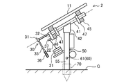
- FIG. 6 is a schematic view of the first solar panel unit viewed from the side.
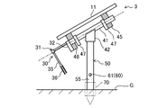
- Drawing 7 is a mimetic diagram seen from the side of the 2nd solar panel unit.
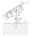
- FIG. 8 is a side view showing a state in which the solar panel unit is installed on the ground.
- This embodiment relates to a solar power generation system including a plurality of solar panels whose angles are adjusted according to the position of the sun.
- the solar power generation system (1) of this embodiment includes a plurality of solar panel units (2, 3).
- the solar power generation system (1) is composed of six solar panel units (2, 3).
- This solar power generation system (1) is to construct a large-scale solar power generation system called a so-called mega solar system by combining a plurality of the systems (1).
- the solar power generation system (1) is provided with a power conditioner that converts the DC power generated by the solar panel units (2, 3) into AC power.
- the solar power generation system (1) of the present embodiment is configured by combining one first solar panel unit (2) and five second solar panel units (3).
- Each solar panel unit (2, 3) is configured to rotate the solar panel (11), which generates direct-current power by sunlight, following the movement of the sun in the east-west direction.
- the solar panel units (2, 3) are arranged in a line in the east-west direction.
- the first solar panel unit (2) shown in FIG. 2 includes an actuator (20) for driving the solar panel (11) and a plurality of solar panels (11) of each solar panel unit (2, 3).
- a link mechanism (30) configured so as to synchronize the rotational operations is provided as a drive mechanism (5).
- the second solar panel unit (3) shown in FIG. 3 is not provided with an actuator (20) for driving the solar panel (11), so that the rotating operations of the plurality of solar panels (11) are synchronized. Only the link mechanism (30) configured as described above is provided as the drive mechanism (5).
- each solar panel unit (2, 3) is connected by the link connecting rod (6), and the movement of the solar panel (11) of the first solar panel unit (2) is the second. It is transmitted to the solar panel (11) of the solar panel unit (3). That is, in the present embodiment, the first solar panel unit (2) is a driving unit, and the second solar panel unit (3) is a driven unit.
- each solar panel unit (2, 3) includes the solar panel (11), a rotating shaft (41) fixed to the solar panel (11), and the rotating shaft ( 41) a support (51) that supports the ground (G), which is a ground contact surface, and a pedestal (50), and the solar panel (11) according to the direction of the sun. 41) and the above-described drive mechanism (5) that rotates around the axis.
- the gantry (50) is provided with the support portion (51) at the upper end portion and a single pile whose lower end portion is a pointed portion (52) embedded in the ground plane (G). (55).
- the support portion (51) is provided with a fixture (not shown) for holding the holding member (42) fixed to the rotating shaft (41).
- each solar panel unit (2, 3) of this embodiment drives a pile (55) using a fixing sleeve (70) provided on the ground (G), and surrounds it. The position is fixed by solidifying with mortar.
- the solar panel (11) has a substantially flat plate shape, and the upper surface is a sunlight receiving surface (11a).
- the solar panel (11) generates direct-current power by receiving sunlight on the light receiving surface (11a). 2 and 3, the solar panel (11) is indicated by a virtual line for convenience.
- a frame (40) is fixed to the back surface (lower surface) of the solar panel (11).
- the frame (40) is connected to the gantry (50) in a state inclined at a predetermined angle with respect to the central axis of the stake (55) as the gantry (50), and the solar panel (11) is 55).
- the frame (40) extends in the tilt direction (vertical direction) of the solar panel (11) and is positioned at the center of the solar panel (11).
- two horizontal rails (43, 44) that are respectively fixed to both ends of the rotary shaft and extend in a direction perpendicular to the axis of the rotating shaft (41) (the width direction of the solar panel (11)).
- the horizontal rail (43) is provided at a position corresponding to both end portions of the rotating shaft (41).
- the bearing block (45, 46) for fixing is fixed.
- the horizontal beam (43, 44) is fixed to the back of the solar panel (11), but the bearing block (45 , 46) is separated from the horizontal beam (43, 44) or temporarily fixed to the horizontal beam (43, 44).
- Each bearing block (45, 46) has a bearing surface (45a, 46a) with which the end of the rotating shaft (41) is fitted.
- the rotating shaft (41) has a positioning plate (47) for positioning the bearing block (45, 46) when the bearing block (45, 46) is attached to the end of the rotating shaft (41). ) Is provided. Then, the positions of the horizontal rails (43, 44) are aligned with both ends of the rotating shaft (41), and the bearing blocks (45, 46) fitted into the both ends of the rotating shaft (41) are inserted into the horizontal rails (43, 44). ). In this state, the horizontal rails (43, 44) are positioned by the positioning plate (47) with respect to the rotating shaft (41) and are also fixed to the solar panel (11). Therefore, the solar panel (11) can be rotated in the circumferential direction of the rotating shaft (41), but does not move in the axial direction of the rotating shaft (41).
- the drive bearing block (46) located on the lower side in the inclination direction of the solar panel (11) includes the link mechanism.
- the link member (31) constituting (30) is fixed.
- the link member (31) is fastened with a fastening member (not shown) such as a bolt while being superimposed on the bearing block (45, 46), and is rotated from the fastening plate (32).
- An arm (33) protruding leftward in the drawing along the axial direction of the shaft (41) is integrally formed.
- the arm (33) is formed from a base portion (34) protruding in the axial direction of the rotating shaft (41) from the fastening plate (32) and a connecting portion (35) extending downward from the tip of the base portion (34). It is formed into a shape.
- the lower end of the connecting portion (35) is a Y-shaped double joint (36), and the link connecting rod (6) is connected to the double joint (36).
- the first solar panel unit (2) on the drive side includes an actuator (20 for adjusting the angle of the solar panel (11) with respect to the rotation shaft (41). ) Is provided with an air cylinder (21). Although the details of the structure of the air cylinder (21) are omitted, the airbag is housed in the case, and the cylinder rod (22) advances and retreats with respect to the case as the airbag expands and contracts.
- the cylinder rod (22) is provided with a joint portion (not shown) at the base portion on the case side, and a portion on the tip side of the joint portion tilts as the cylinder rod (22) advances and retreats. ing.
- the rear end of the air cylinder (21) is fixed to the side of the pile (55) which is the gantry (50) via the bracket (25). Moreover, the front-end
- the rod connection pin (37) provided in the fastening plate (32).
- the cylinder driving component (26) for driving the air cylinder (21) is provided on the pile (55) of the first solar panel unit (2).
- the second solar panel unit (3) on the driven side is provided with an air cylinder (21) as an actuator (20) and an air cylinder (21) on a gantry (50). There is no bracket (25) to attach to a pile (55). Further, the fastening plate (32) is not provided with the rod connecting pin (37).
- each link member (35) is connected by the link connecting rod (6).
- the movement of the solar panel (11) of the first solar panel unit (2) is transmitted to the solar panel (11) of the second solar panel unit (3), and each solar panel (11 ) Behave the same.
- the second solar panel unit (3) on the driven side does not require the rod connecting pin (37), but the parts are shared with the fastening plate (32) of the first solar panel unit (2).
- a fastening plate (32) provided with a rod connecting pin (37) may be used.
- a hole (61) is formed as an alignment mechanism (60).
- This through-hole (61) is a base (50) of each solar panel unit (2, 3) in the state of FIG. 1 in which the first solar panel unit (2) and the second solar panel unit (3) are installed. ) At the same height in a straight line in the east-west direction. Specifically, in order to align the positions of the through holes (61) of the respective piles (55) on a straight line, the solar power generation system (1) of the present embodiment receives the laser light projecting unit (66) and the light receiving unit. Each solar panel unit is determined by positioning the pile (55) so that the laser positioning unit (65) having the section (67) and the straight laser beam pass through each through hole (61) is used. (2, 3) is positioned.
- This solar power generation system (1) is installed as follows.
- each solar panel unit (2, 3) is fixed to the ground (G)
- the pile (55) and the solar panel (11) are not fixed, and the ground (G) Sleeves (70) for striking are embedded in a row in the east-west direction.
- the ground (G) is not particularly leveled and may not be flat.
- the pile (55) is inserted into the sleeve (70) and driven into the ground (G) so that the heights of the piles (55) are substantially aligned.
- the light projecting portion (66) and the light receiving portion (67) of the laser positioning unit (65) are arranged to face each other with the reference height of the through hole (61) of the pile (55). Since the laser beam has a straightness, the laser beam passes through all the through holes (61) if the piles (55) have the same height.
- the solar panel unit (2, 3) is not aligned with the other, so the height is adjusted. And align the height of the piles (55) of all the solar panel units (2, 3) so that the laser beam passes through all the through holes (61). Harden the part with mortar. Since the sleeves (70) are arranged in a line in the east-west direction, if the positions of the through holes (61) are aligned, the pile (55) has a constant height and is not inclined. Fixed to the ground (G). The above is the arrangement process of the present invention.
- the work (installation process) of attaching the frame (40) fixed to the back surface of the solar panel (11) to the pile (55) is then performed.
- the holding member (42) of the frame (40) is attached to the support portion (51) of the pile (55) with a fixing bracket.
- the rotation shaft (41) is fixed to the pile (55) which is the gantry (50). Since the solar panel (11) can be rotated with respect to the rotating shaft (41), the angle can be adjusted with respect to the pile (55).
- the air cylinder (20) attaches to the mount (50) of the first solar panel unit (2). Specifically, the rear end of the air cylinder (20) is fixed to the side surface of the pile (55) via a bracket (25), while the tip of the cylinder rod (22) is attached to the bearing block ( Connect to the rod connecting pin (37) of the fastening plate (32) fixed to 46). Further, the air cylinder (20) is connected to the cylinder drive component (26) so that compressed air can be supplied to the air cylinder (20).
- the link connecting rod (6) is connected to the double joint (36) of the connecting portion (35) of the link member (31) of each solar panel unit (2, 3).
- the link connecting rod (6) By connecting the link members (31) with the link connecting rod (6), the air cylinder (20) is driven to rotate the solar panel (11) of the first solar panel unit (2). The movement is transmitted to the solar panel (11) of each second solar panel unit (3) through the link connecting rod (6) and the link member (31). Therefore, the solar panels (11) of all the solar panel units (2, 3) are in a state of rotating synchronously.
- the angle of the solar panel (11) is adjusted according to the direction of the sun.
- This solar power generation system (1) is provided with a solar radiation sensor (not shown), for example, to detect the direction of the sun. Then, an angle at which the solar panel (11) is in a state corresponding to the direction of the sun is obtained by a controller (not shown), and the solar panel (11) is the actuator (20) so that the angle is obtained.
- the air cylinder (20) is controlled.
- the frame (40) rotates about the rotation axis (41), and the solar panel (11) rotates accordingly.
- the operation is transmitted to the second solar panel unit (3) via the link connecting rod (6) and the link member (31). .
- the frame (40) and the solar panel (11) of the second solar panel unit (3) move in the same manner as the first solar panel unit (2), and all the solar panel units (2, 3)
- the solar panel (11) is adjusted to the same angle according to the direction of the sun.
- the stand (50) of each solar panel unit (2, 3) is composed of a single pile (55), and the pile (55) is driven into the ground (G).
- 50) can be fixed to the ground (G), so that the height of the gantry (50) can be adjusted without performing leveling work even when the ground (G) is not flat as shown in FIG. Therefore, since the man-hour required for the leveling work can be omitted, it is possible to easily install the solar power generation system (1) and to reduce the cost.
- the through-hole (61) is formed in a pile (55) and it is made to let a laser beam pass to this through-hole (61), six solar panel units (2, 3) It can be easily installed in a row with the same height.
- the laser positioning unit (65) is used not only when the photovoltaic power generation system (1) is installed, but, for example, every time a predetermined period elapses during the operation of the photovoltaic power generation system (1), It is also possible to use it to detect the position shift of 50) periodically. By doing so, it becomes possible to improve the operational stability of the photovoltaic power generation system (1).
- the laser positioning unit (65) is used in order to align the positions of the solar panel units (2, 3).
- the positions may be aligned.
- the structure of the frame (40) and the link member (31) described in the above embodiment is an example.
- the frame The configuration of (40) and the link member (31) may be changed as appropriate.
- the solar power generation system (1) is comprised by six solar panel units (2, 3), the number of solar panel units (2, 3) is a system. It may be appropriately changed according to the power required for the device.
- the gantry (50) is attached to one pile.
- the gantry (50) is attached to one pile.
- the present invention is a solar panel unit that includes a solar panel and a drive mechanism that drives and rotates the solar panel, and a solar that is configured by using a plurality of such solar panel units. This is useful for a photovoltaic power generation system and an installation method for installing this photovoltaic power generation system outdoors.
- Photovoltaic power generation system 1st solar panel unit 3 2nd solar panel unit 5 Drive mechanism 6 Link connecting rod 11 Solar panel 20 Actuator 30 Link mechanism 41 Rotating shaft 50 Base 51 Support part 55 Pile 60 Positioning mechanism 61 Through hole G Ground plane
Landscapes
- Engineering & Computer Science (AREA)
- Life Sciences & Earth Sciences (AREA)
- Sustainable Development (AREA)
- Physics & Mathematics (AREA)
- Sustainable Energy (AREA)
- Thermal Sciences (AREA)
- Chemical & Material Sciences (AREA)
- Combustion & Propulsion (AREA)
- Mechanical Engineering (AREA)
- General Engineering & Computer Science (AREA)
- Photovoltaic Devices (AREA)
Abstract
太陽光パネル(11)に固定された回動軸(41)を支持する支持部(51)を備えて接地面に固定される架台(50)を有し、太陽の向きに応じて太陽光パネル(11)を駆動機構(5)で回動軸(41)の軸心周りに回動させる太陽光パネルユニット(2)において、上端部に支持部(51)が設けられ下端部が接地面に埋設される1本の杭(55)により架台(50)を構成し、杭(55)の打ち込み深さを調整することで架台(50)の高さ調整を容易に行えるようにする。こうすることで、接地面の整地作業をしなくても正確な高さに設置できるようにして、複数台のリンク機構(30)を容易に連結できるようにする。
Description
本発明は、太陽光パネルと該太陽光パネルを駆動して回動させる駆動機構とを備えた太陽光パネルユニット、この太陽光パネルユニットを複数用いることで構成される太陽光発電システム、及びこの太陽光発電システムを室外に設置するときの設置方法に関するものである。
従来より、太陽光パネルと、太陽光パネルを回動させるためのアクチュエータとを備える太陽光パネルユニットが知られている。この太陽光パネルユニットでは、太陽光パネルの受光面を太陽の方向に追尾させるように、アクチュエータで太陽光パネルを回動させることで、太陽光パネルによる発電量をパネル固定式よりも増やすことができるようにしている。この種の太陽光パネルユニットとして、例えば特許文献1には、作動液を充満した密閉容器からなる受熱槽と、該受熱槽内において太陽光の輻射熱を受けて膨張する作動液の圧力によって作動するアクチュエータとを備えた太陽光パネルユニットが開示されている。アクチュエータは、一端が太陽光パネルに固定されたピストンを有していて、作動液の圧力によってピストンが往復運動を行うことにより、太陽光パネルが回動する。
特許文献1の太陽光パネルユニットは、1つの架台で1つの太陽光パネルを保持したユニットである。複数の太陽光パネルを設置する場合には、各太陽光パネルの数だけ架台を設置して複数の太陽光パネルユニットが組み立てられ、太陽光パネルユニット毎に太陽光パネルが駆動される。
また、本願出願人は、複数の太陽光パネルを設置するシステムにおいて、アクチュエータを備えた太陽光パネルユニットと、アクチュエータを設けない太陽光パネルユニットとをリンク機構で連結し、1つのアクチュエータで複数の太陽光パネルを駆動する機構に関する発明を既に出願している(特願2011-122553号)。
特許文献1の太陽光パネルユニットを地上に複数台設置し、リンク機構で連結すると、アクチュエータの数を減らし、コスト低減を実現できると考えられる。しかしながら、すべての架台は通常は同じ形状に製作されるので、各太陽光パネルユニットを設置する地面の高さが異なると、連結すべき各ユニットのリンク機構の位置がずれてしまう。そのため、複数の太陽光パネルユニットを接地する場合には、設置前に整地作業を行って接地面の高さを均一にする必要があり、設置工程が複雑になってしまう問題が生じる。また、従来の太陽光パネルユニットでは架台の設置面積が広いので、1台だけを設置する場合でも整地作業が必要になる問題がある。
本発明は、このような問題点に鑑みてなされたものであり、その目的は、整地作業をしなくても太陽光パネルユニットを正確な高さに設置できるようにし、複数台を設置する場合でも、各太陽光パネルの高さを正確かつ容易に揃えられるようにすることである。
第1の発明は、太陽光パネル(11)と、該太陽光パネル(11)に固定された回動軸(41)と、該回動軸(41)を支持する支持部(51)を備えるとともに接地面(G)に固定される架台(50)と、太陽の向きに応じて上記太陽光パネル(11)を上記回動軸(41)の軸心周りに回動させる駆動機構(5)と、を備えた太陽光パネルユニット(2,3)を前提としている。
そして、この太陽光パネルユニット(2,3)は、上記架台(50)が、上端部に上記支持部(51)が設けられるとともに下端部が接地面(G)に埋設される1本の杭(55)により構成されていることを特徴としている。
この第1の発明では、杭(55)を接地面(G)に打ち込むことにより、架台(50)が接地面(G)に固定される。架台(50)である杭(55)には、その上端部の支持部(51)に回動軸(41)が支持され、回動軸(41)には太陽光パネル(11)が固定される。太陽光パネル(11)は、太陽光パネルユニット(2,3)に設けられている駆動機構(5)により駆動され、太陽の向きに応じて架台(50)に対する角度が調整される。このことにより、太陽光パネル(11)は、太陽の動きに追随して角度が変化し、効率よく電力を発生する。
第2の発明は、第1の発明の太陽光パネルユニット(2,3)を複数備えた太陽光発電システム(1)を対象としている。
そして、この太陽光発電システム(1)は、上記駆動機構(5)として、太陽光パネル(11)を駆動するアクチュエータ(20)と、複数の太陽光パネル(11)の回動動作を同期させるように構成されたリンク機構(30)とを有する駆動側の第1太陽光パネルユニット(2)と、上記駆動機構(5)として、太陽光パネル(11)を駆動するアクチュエータ(20)を備えずに、複数の太陽光パネル(11)の回動動作を同期させるように構成されたリンク機構(30)を有する従動側の第2太陽光パネルユニット(3)と、を備え、1台の第1太陽光パネルユニット(2)と複数台の第2太陽光パネルユニット(3)とがリンク連結ロッド(6)で接続されていることを特徴としている。
この第2の発明では、第1太陽光パネルユニット(2)に設けられたアクチュエータ(20)により、該第1太陽光パネルユニット(2)の太陽光パネル(11)が角度調整される。このアクチュエータ(20)の駆動力は、リンク機構(30)とリンク連結ロッド(6)を介して第2太陽光パネルユニット(3)の太陽光パネル(11)にも伝達される。このことにより、第1太陽光パネルユニット(2)の太陽光パネル(11)の動きと第2太陽光パネルユニット(3)の太陽光パネル(11)の動きが同期する。この第2の発明においても、各太陽光パネルユニット(2,3)の高さ調整は杭(55)の打ち込み深さを調整することにより行われる。
第3の発明は、第2の発明において、各太陽光パネルユニット(2,3)の架台(50)が同じ高さで一直線上に配列されるように各架台(50)の位置を調整する位置合わせ機構(60)が設けられていることを特徴としている。
第4の発明は、第3の発明において、上記位置合わせ機構(60)が、上記各太陽光パネルユニット(2,3)の架台(50)の同じ位置をレーザー光が透過するように上記杭(55)に形成された貫通孔(61)により構成されていることを特徴としている。
これらの第3,第4の発明では、各太陽光パネルユニット(2,3)を設置する際に、杭(55)に形成される貫通孔(61)とその貫通孔(61)に通すレーザー光を発生させるユニットなどの位置合わせ機構(60)を用いることにより、各太陽光パネルユニット(2,3)の架台(50)の位置が揃えられる。
第5の発明は、第3の発明の複数台の太陽光パネルユニット(2,3)を地面に設置する太陽光発電システム(1)の設置方法を対象としている。
そして、この設置方法は、各太陽光パネルユニット(2,3)の架台(50)を構成する杭(55)を地面に打ち込んで、各杭(55)を同じ高さで一直線上に配列する配列工程と、各太陽光パネル(11)を各架台(50)に設置する設置工程と、各太陽光パネルユニット(2,3)をリンク連結ロッド(6)で連結する連結工程と、を順に行うことを特徴としている。
第6の発明は、第4の発明の複数台の太陽光パネルユニット(2,3)を地面に設置する太陽光発電システム(1)の設置方法を対象としている。
そして、この設置方法は、各太陽光パネルユニット(2,3)の架台(50)を構成する杭(55)を地面に打ち込んで各杭(55)を同じ高さで一直線上に配列する配列工程と、各太陽光パネル(11)を各架台(50)に設置する設置工程と、各太陽光パネルユニット(2,3)をリンク連結ロッド(6)で連結する連結工程とを順に行い、上記配列工程では、各杭(55)に形成された貫通孔(61)にレーザー光を透過させることにより、各太陽光パネルユニット(2,3)の架台(50)の位置合わせを行うことを特徴としている。
これらの第5,第6の発明では、配列工程と設置工程と連結工程を順に行うことにより、複数の太陽光パネルユニット(2,3)が、位置の揃った状態で設置される。
本発明によれば、太陽光パネルユニット(2,3)の架台(50)を1本の杭(55)にしたことにより、杭(55)を接地面(G)に打ち込むだけで架台(50)を設置することができる。そして、太陽光パネル(11)は、接地面(G)への杭(55)の打ち込み深さを調整することにより、接地面(G)に対して正確な高さに設置することができる。したがって、本発明によれば、接地面(G)の整地作業をしなくても、太陽光パネルユニット(2,3)を正確な高さに設置できる。また、太陽光パネルユニット(2,3)を複数台設置する場合でも、各太陽光パネル(11)の高さを正確かつ容易に揃えることができる。
上記第2の発明によれば、第1の発明と同様、太陽光パネルユニット(2,3)を設置する際に、接地面(G)に対する杭(55)の打ち込み深さを調整することにより、各太陽光パネル(11)の高さを容易に揃えることができる。また、各太陽光パネルユニット(2,3)を設置した状態では、各太陽光パネルユニット(2,3)のリンク機構(30)の高さも揃っているので、リンク連結ロッド(6)で接続したときの太陽光パネル(11)の円滑な動作を保証できる。この第2の発明でも、各太陽光パネルユニット(2,3)を設置する際に接地面(G)を整地する作業が不要であるから、設置工程を簡単にしてコスト低減を図ることが可能になる。
上記第3,第4の発明によれば、各太陽光パネルユニット(2,3)を設置する際に、杭(55)に形成される貫通孔(61)とその貫通孔(61)に通すレーザー光を発生させるレーザー光ユニットなどの位置合わせ機構(60)を用いることにより、各太陽光パネルユニット(2,3)の架台(50)の位置を容易に揃えることができるので、設置工程をより簡単に行うことが可能になる。
上記第5,第6の発明によれば、配列工程と設置工程と連結工程を順に行うことにより、複数の太陽光パネルユニット(2,3)を、簡単且つ確実に位置の揃った状態にして設置することができる。また、配列工程では、架台(50)である杭(55)を接地面(G)に打ち込むだけでよいので、整地作業は不要である。そして、位置合わせ機構(60)を用いることにより、各太陽光パネルユニット(2,3)の位置を簡単且つ確実に一直線上に揃えることが可能となる。
以下、本発明の実施形態を図面に基づいて詳細に説明する。
この実施形態は、太陽の位置に合わせて角度が調整される複数の太陽光パネルを備えた太陽光発電システムに関するものである。
(システム構成)
図1に示すように、本実施形態の太陽光発電システム(1)は、複数台の太陽光パネルユニット(2,3)を備えている。この実施形態では、6台の太陽光パネルユニット(2,3)により太陽光発電システム(1)が構成されている。この太陽光発電システム(1)は、当該システム(1)を複数組み合わせることにより、いわゆるメガソーラーシステムと呼ばれる大規模太陽光発電システムを構築するものである。なお、図示していないが、この太陽光発電システム(1)には、太陽光パネルユニット(2,3)で発電した直流電力を交流電力に変換するパワーコンディショナが設けられている。
図1に示すように、本実施形態の太陽光発電システム(1)は、複数台の太陽光パネルユニット(2,3)を備えている。この実施形態では、6台の太陽光パネルユニット(2,3)により太陽光発電システム(1)が構成されている。この太陽光発電システム(1)は、当該システム(1)を複数組み合わせることにより、いわゆるメガソーラーシステムと呼ばれる大規模太陽光発電システムを構築するものである。なお、図示していないが、この太陽光発電システム(1)には、太陽光パネルユニット(2,3)で発電した直流電力を交流電力に変換するパワーコンディショナが設けられている。
まず、太陽光パネルユニット(2,3)について説明する。本実施形態の太陽光発電システム(1)は、1台の第1太陽光パネルユニット(2)と5台の第2太陽光パネルユニット(3)を組み合わせることにより構成されている。各太陽光パネルユニット(2,3)は、太陽光により直流電力を発生する太陽光パネル(11)を、太陽の動きに追随させて東西の方向に回動させるように構成されている。各太陽光パネルユニット(2,3)は、東西方向に一列に並べて配置されている。
図2に示す第1太陽光パネルユニット(2)には、太陽光パネル(11)を駆動するアクチュエータ(20)と、各太陽光パネルユニット(2,3)の複数の太陽光パネル(11)の回動動作を同期させるように構成されたリンク機構(30)とが、駆動機構(5)として設けられている。図3に示す第2太陽光パネルユニット(3)には、太陽光パネル(11)を駆動するアクチュエータ(20)は設けられず、複数の太陽光パネル(11)の回動動作を同期させるように構成されたリンク機構(30)のみが駆動機構(5)として設けられている。
そして、各太陽光パネルユニット(2,3)のリンク機構(30)がリンク連結ロッド(6)で連結され、第1太陽光パネルユニット(2)の太陽光パネル(11)の動きが第2太陽光パネルユニット(3)の太陽光パネル(11)に伝達される。つまり、本実施形態において、第1太陽光パネルユニット(2)は駆動側のユニットになっており、第2太陽光パネルユニット(3)は従動側のユニットになっている。
第1太陽光パネルユニット(2)と第2太陽光パネルユニット(3)は、アクチュエータ(20)の有無を除いては実質的に同じように構成されている。具体的には、各太陽光パネルユニット(2,3)は、上記太陽光パネル(11)と、該太陽光パネル(11)に固定された回動軸(41)と、該回動軸(41)を支持する支持部(51)を備えるとともに接地面である地面(G)に固定される架台(50)と、太陽の向きに応じて上記太陽光パネル(11)を上記回動軸(41)の軸心周りに回動させる上述の駆動機構(5)とを有している。
本実施形態において、上記架台(50)は、上端部に上記支持部(51)が設けられるとともに、下端部が接地面(G)に埋設される尖端部(52)になった1本の杭(55)により構成されている。上記支持部(51)には、回動軸(41)に固定された保持用部材(42)を保持するための固定金具(図示せず)が設けられている。本実施形態の各太陽光パネルユニット(2,3)は、図8に示すように、地面(G)に設けられた固定用のスリーブ(70)を使って杭(55)を打ち込み、その周囲をモルタルで固めることにより位置が固定される。
図2及び図3において、上記太陽光パネル(11)はほぼ平板状であり、上面が太陽光の受光面(11a)になっている。太陽光パネル(11)は、太陽光を受光面(11a)に受けることによって、直流電力を発生する。図2,3において、太陽光パネル(11)は便宜上仮想線で示している。
太陽光パネル(11)の裏面(下面)にはフレーム(40)が固定されている。フレーム(40)は、架台(50)である杭(55)の中心軸に対して予め定められた角度で傾斜する状態で上記架台(50)と連結され、太陽光パネル(11)が杭(55)に対して傾斜するようになっている。フレーム(40)は、太陽光パネル(11)の傾斜方向(上下方向)に延在して該太陽光パネル(11)の中心に位置する上記回動軸(41)と、回動軸(41)の両端にそれぞれ固定されて該回動軸(41)の軸直角方向(太陽光パネル(11)の幅方向)に延在する2本の横桟(43,44)とを有している。横桟(43)は、回動軸(41)の両端部に対応する位置に設けられている。
第1太陽光パネルユニット(2)の斜視図、分解斜視図及び模式側面図である図2,図4及び図6と、第2太陽光パネルユニット(3)の斜視図、分解斜視図及び模式側面図である図3,図5及び図7に示すように、横桟(43,44)の下面には、各横桟(43,44)を回動軸(41)に回転可能に装着するための軸受けブロック(45,46)が固定される。各太陽光パネルユニット(2,3)を地面(G)に設置する前の状態では、太陽光パネル(11)の裏面に横桟(43,44)が固定されているが、軸受けブロック(45,46)は横桟(43,44)から分離されているか、横桟(43,44)に仮止めされた状態である。
各軸受けブロック(45,46)には、回動軸(41)の端部が嵌合する軸受け面(45a,46a)が形成されている。回動軸(41)には、該回動軸(41)の端部に軸受けブロック(45,46)を装着するときに、軸受けブロック(45,46)の位置決めをするための位置決めプレート(47)が設けられている。そして、回動軸(41)の両端部に横桟(43,44)の位置を合わせ、回動軸(41)の両端部にはめ込んだ軸受けブロック(45,46)を横桟(43,44)に固定する。この状態で、横桟(43,44)は、回動軸(41)に対して位置決めプレート(47)で位置決めされるとともに、太陽光パネル(11)にも固定されている。したがって、太陽光パネル(11)は、回動軸(41)の周方向へ回動可能になる一方、回動軸(41)の軸方向へは移動しない。
上記横桟(43,44)に設けられる軸受けブロック(45,46)のうち、太陽光パネル(11)の傾斜方向の下方側に位置する駆動用の軸受けブロック(46)には、上記リンク機構(30)を構成するリンク部材(31)が固定される。リンク部材(31)は、上記軸受けブロック(45,46)に重ねた状態でボルトなどの締結部材(図示せず)で固定される締結プレート(32)と、この締結プレート(32)から回動軸(41)の軸方向に沿って図の左側へ突出するアーム(33)とが一体に形成されたものである。アーム(33)は、締結プレート(32)から回動軸(41)の軸方向へ突出する基部(34)と、基部(34)の先端から下方へ延出する連結部(35)とからL形に形成されている。また、連結部(35)の下端はY形の二山ジョイント(36)になっていて、この二山ジョイント(36)にリンク連結ロッド(6)が連結される。
駆動側である第1太陽光パネルユニット(2)には、図2及び図4に示すように、太陽光パネル(11)を回動軸(41)に対して角度調整するためのアクチュエータ(20)としてエアシリンダ(21)が設けられている。エアシリンダ(21)は、構造の詳細は省略するがケースの中にエアバッグが収納され、エアバッグの拡縮に伴ってシリンダロッド(22)がケースに対して進退する。このシリンダロッド(22)は、ケース側の根元部分にジョイント部(図示せず)が設けられ、このジョイント部よりも先端側の部分がシリンダロッド(22)の進退に伴って傾動するようになっている。
エアシリンダ(21)は、後端部がブラケット(25)を介して架台(50)である杭(55)の側面に固定されている。また、エアシリンダ(21)のシリンダロッド(22)の先端部(23)は、締結プレート(32)に設けられているロッド連結ピン(37)に連結されている。エアシリンダ(21)に圧縮空気が供給されるとシリンダロッド(22)が進退し、それに伴ってロッド連結ピン(37)の位置が変化することにより、太陽光パネル(11)が回動軸(41)を中心として回転する。
上記第1太陽光パネルユニット(2)の杭(55)には、エアシリンダ(21)を駆動するためのシリンダ駆動部品(26)が設けられている。
従動側である第2太陽光パネルユニット(3)には、図3,図5に示すように、アクチュエータ(20)であるエアシリンダ(21)や、エアシリンダ(21)を架台(50)である杭(55)に取り付けるためのブラケット(25)は設けられていない。また、締結プレート(32)にもロッド連結ピン(37)は設けられていない。
第1太陽光パネルユニット(2)と第2太陽光パネルユニット(3)は、各リンク部材(35)の連結部(35)がリンク連結ロッド(6)で連結される。こうすることにより、第1太陽光パネルユニット(2)の太陽光パネル(11)の動きが第2太陽光パネルユニット(3)の太陽光パネル(11)に伝達され、各太陽光パネル(11)が同じ動作をする。
なお、従動側である第2太陽光パネルユニット(3)には、ロッド連結ピン(37)は不要であるが、第1太陽光パネルユニット(2)の締結プレート(32)と部品を共通化するために、ロッド連結ピン(37)を設けた締結プレート(32)を用いてもよい。
第1太陽光パネルユニット(2)及び第2太陽光パネルユニット(3)の架台(50)を構成するそれぞれの杭(55)には、杭(55)の上端からの寸法が同じ位置に貫通孔(61)が位置合わせ機構(60)として形成されている。
この貫通孔(61)は、第1太陽光パネルユニット(2)と第2太陽光パネルユニット(3)を設置した図1の状態で、各太陽光パネルユニット(2,3)の架台(50)を同じ高さで東西方向に一直線上に配列することを目的として形成されている。具体的には、各杭(55)の貫通孔(61)の位置を一直線上に揃えるために、本実施形態の太陽光発電システム(1)では、レーザー光の投光部(66)と受光部(67)とを有するレーザー位置決めユニット(65)が用いられ、直進性のあるレーザー光が各貫通孔(61)を通るように杭(55)の位置を決めることで、各太陽光パネルユニット(2,3)を位置決めするようにしている。
(太陽光発電システムの設置方法)
この太陽光発電システム(1)の設置は以下のようにして行われる。
この太陽光発電システム(1)の設置は以下のようにして行われる。
まず、各太陽光パネルユニット(2,3)を地面(G)に固定する際、杭(55)と太陽光パネル(11)とは固定されていない状態であり、地面(G)には、くい打ちをするためのスリーブ(70)が東西方向に一列に並ぶ状態で埋め込まれる。本実施形態では、図8に示すように地面(G)は特に整地されず、平坦になっていなくてもよい。
本実施形態では、このスリーブ(70)に杭(55)を挿入しながら地面(G)に打ち込み、杭(55)の高さをほぼ揃えるようにする。この状態で、レーザー位置決めユニット(65)の投光部(66)と受光部(67)を杭(55)の貫通孔(61)の基準高さに揃えて対向させるように配置する。レーザー光は直進性を有しているので、杭(55)の高さが揃っていればすべての貫通孔(61)をレーザー光が通過する。
このとき、レーザー光が貫通孔(61)を通過しない太陽光パネルユニット(2,3)があれば、その太陽光パネルユニット(2,3)は高さが他と揃っていないので高さ調整を行い、すべての太陽光パネルユニット(2,3)の杭(55)の高さを揃えてレーザー光がすべての貫通孔(61)を通過するようにした状態で、杭(55)の下端部をモルタルで固める。上記各スリーブ(70)は東西方向に一列に並んでいるので、上記貫通孔(61)の位置が揃っていれば、杭(55)は高さが一定で、しかも傾きも生じていない状態となり、地面(G)に固定される。以上が本発明の配列工程である。
杭(55)が地面(G)に固定されると、次に太陽光パネル(11)の裏面に固定されたフレーム(40)を杭(55)に取り付ける作業(設置工程)を行う。具体的には、フレーム(40)の保持用部材(42)を杭(55)の支持部(51)に対して固定金具で取り付ける。こうすることにより、架台(50)である杭(55)に対して回動軸(41)が固定される。太陽光パネル(11)は、回動軸(41)に対して回動可能であるから、杭(55)に対しても角度調整可能な状態となる。
次に、第1太陽光パネルユニット(2)の架台(50)にエアシリンダ(20)を取り付ける。具体的には、杭(55)の側面にブラケット(25)を介してエアシリンダ(20)の後端を固定する一方、シリンダロッド(22)の先端部を、フレーム(40)の軸受けブロック(46)に固定されている締結プレート(32)のロッド連結ピン(37)に連結する。また、エアシリンダ(20)をシリンダ駆動部品(26)と接続し、エアシリンダ(20)に圧縮エアを供給できる状態とする。
次に、各太陽光パネルユニット(2,3)のリンク部材(31)が有している連結部(35)の二山ジョイント(36)にリンク連結ロッド(6)を連結ピン(図示せず)により連結する連結工程を行う。各リンク部材(31)をリンク連結ロッド(6)で連結することにより、エアシリンダ(20)を駆動して第1太陽光パネルユニット(2)の太陽光パネル(11)を回動させると、その動きがリンク連結ロッド(6)及びリンク部材(31)を介して各第2太陽光パネルユニット(3)の太陽光パネル(11)に伝達される。したがって、すべての太陽光パネルユニット(2,3)の太陽光パネル(11)が同期して回動する状態となる。
-運転動作-
本実施形態の太陽光発電システム(1)では、太陽の方角に応じて太陽光パネル(11)の角度が調整される。
本実施形態の太陽光発電システム(1)では、太陽の方角に応じて太陽光パネル(11)の角度が調整される。
この太陽光発電システム(1)には、例えば日射センサ(図示せず)が設けられ、太陽の方位が検出される。そして、コントローラ(図示せず)により、太陽光パネル(11)が太陽の方位に対応する状態となる角度が求められ、太陽光パネル(11)がその角度になるようにアクチュエータ(20)であるエアシリンダ(20)が制御される。
エアシリンダ(20)が駆動されてシリンダロッド(22)が進退すると、回動軸(41)を中心としてフレーム(40)が回動し、それに伴って太陽光パネル(11)が回動する。第1太陽光パネルユニット(2)のフレーム(40)が回動すると、その動作がリンク連結ロッド(6)とリンク部材(31)を介して第2太陽光パネルユニット(3)に伝達される。そして、第2太陽光パネルユニット(3)のフレーム(40)及び太陽光パネル(11)が第1太陽光パネルユニット(2)と同じ動きをし、すべての太陽光パネルユニット(2,3)の太陽光パネル(11)が、太陽の方位に応じて同じ角度に調整される。
このように、本実施形態では、すべての太陽光パネル(11)が太陽の方位に合う方向を向き、各太陽光パネル(11)への太陽光の入射角度を最適角度に設定できるので、効率のよい太陽光発電が行われる。
-実施形態の効果-
本実施形態によれば、各太陽光パネルユニット(2,3)の架台(50)を1本の杭(55)で構成し、この杭(55)を地面(G)に打ち込むことによって架台(50)を地面(G)に固定できるようにしているので、図8に示すように地面(G)が平坦でない場合でも整地作業を行わずに架台(50)の高さを揃えられる。従って、整地作業に要する工数を省くことができるから、太陽光発電システム(1)の設置を容易に行うことが可能になり、コストダウンも可能になる。
本実施形態によれば、各太陽光パネルユニット(2,3)の架台(50)を1本の杭(55)で構成し、この杭(55)を地面(G)に打ち込むことによって架台(50)を地面(G)に固定できるようにしているので、図8に示すように地面(G)が平坦でない場合でも整地作業を行わずに架台(50)の高さを揃えられる。従って、整地作業に要する工数を省くことができるから、太陽光発電システム(1)の設置を容易に行うことが可能になり、コストダウンも可能になる。
また、上記実施形態では、杭(55)に貫通孔(61)を形成し、この貫通孔(61)にレーザー光を通すようにしているので、6台の太陽光パネルユニット(2,3)の高さを揃えた状態で一列に並べて設置するのを容易に行うことができる。
また、上記レーザー位置決めユニット(65)は、太陽光発電システム(1)の設置時にのみ使用するだけでなく、例えば太陽光発電システム(1)の運転中に所定期間が経過する毎に、架台(50)の位置のずれを定期的に検出するのに使用することも可能である。そうすることにより、太陽光発電システム(1)の動作の安定性を高めることが可能になる。
《その他の実施形態》
上記実施形態については、以下のような構成としてもよい。
上記実施形態については、以下のような構成としてもよい。
例えば、上記実施形態では、各太陽光パネルユニット(2,3)の位置を揃えるためにレーザー位置決めユニット(65)を用いるようにしているが、レーザー光以外の手段を用いて架台(50)の位置を揃えるようにしてもよい。
また、上記実施形態で説明したフレーム(40)やリンク部材(31)の構造は一例であり、本発明においては架台(50)が1本の杭(55)で連結されている限りは、フレーム(40)やリンク部材(31)の構成は適宜変更してもよい。
また、上記実施形態では、6台の太陽光パネルユニット(2,3)により太陽光発電システム(1)を構成するようにしているが、太陽光パネルユニット(2,3)の台数は、システムに要求される電力等に応じて適宜変更してもよい。
さらに、駆動機構を備えた第1太陽光パネルユニット(2)を1台だけ設置し、第2太陽光パネルユニット(3)を用いないシステムにする場合でも、架台(50)を1本の杭(55)で構成することにより、設置面積の広い架台(50)を用いる従来のものに比べて設置を容易に行うことは可能である。
なお、以上の実施形態は、本質的に好ましい例示であって、本発明、その適用物、あるいはその用途の範囲を制限することを意図するものではない。
以上説明したように、本発明は、太陽光パネルと該太陽光パネルを駆動して回動させる駆動機構とを備えた太陽光パネルユニット、この太陽光パネルユニットを複数用いることで構成される太陽光発電システム、及びこの太陽光発電システムを室外に設置するときの設置方法について有用である。
1 太陽光発電システム
2 第1太陽光パネルユニット
3 第2太陽光パネルユニット
5 駆動機構
6 リンク連結ロッド
11 太陽光パネル
20 アクチュエータ
30 リンク機構
41 回動軸
50 架台
51 支持部
55 杭
60 位置合わせ機構
61 貫通孔
G 接地面
2 第1太陽光パネルユニット
3 第2太陽光パネルユニット
5 駆動機構
6 リンク連結ロッド
11 太陽光パネル
20 アクチュエータ
30 リンク機構
41 回動軸
50 架台
51 支持部
55 杭
60 位置合わせ機構
61 貫通孔
G 接地面
Claims (6)
- 太陽光パネル(11)と、該太陽光パネル(11)に固定された回動軸(41)と、該回動軸(41)を支持する支持部(51)を備えるとともに接地面(G)に固定される架台(50)と、太陽の向きに応じて上記太陽光パネル(11)を上記回動軸(41)の軸周りに回動させる駆動機構(5)と、を備えた太陽光パネルユニットであって、
上記架台(50)は、上端部に上記支持部(51)が設けられるとともに下端部が接地面(G)に埋設される1本の杭(55)により構成されていることを特徴とする太陽光パネルユニット。 - 請求項1の太陽光パネルユニット(2,3)を複数備えた太陽光発電システムであって、
上記駆動機構(5)として、太陽光パネル(11)を駆動するアクチュエータ(20)と、複数の太陽光パネル(11)の回動動作を同期させるように構成されたリンク機構(30)とを有する駆動側の第1太陽光パネルユニット(2)と、
上記駆動機構(5)として、太陽光パネル(11)を駆動するアクチュエータ(20)を備えずに、複数の太陽光パネル(11)の回動動作を同期させるように構成されたリンク機構(30)を有する従動側の第2太陽光パネルユニット(3)と、を備え、
1台の第1太陽光パネルユニット(2)と複数台の第2太陽光パネルユニット(3)とがリンク連結ロッド(6)で接続されていることを特徴とする太陽光発電システム。 - 請求項2において、
各太陽光パネルユニット(2,3)の架台(50)が同じ高さで一直線上に配列されるように各架台(50)の位置を調整する位置合わせ機構(60)が設けられていることを特徴とする太陽光発電システム。 - 請求項3において、
上記位置合わせ機構(60)は、上記各太陽光パネルユニット(2,3)の架台(50)の同じ位置をレーザー光が透過するように上記杭(55)に形成された貫通孔(61)により構成されていることを特徴とする太陽光発電システム。 - 請求項3に記載の複数台の太陽光パネルユニット(2,3)を地面に設置する太陽光発電システムの設置方法であって、
各太陽光パネルユニット(2,3)の架台(50)を構成する杭(55)を地面(G)に打ち込んで、各杭(55)を同じ高さで一直線上に配列する配列工程と、
各太陽光パネル(11)を各架台(50)に設置する設置工程と、
各太陽光パネルユニット(2,3)をリンク連結ロッド(6)で連結する連結工程と、
を順に行うことを特徴とする太陽光発電システムの設置方法。 - 請求項4に記載の複数台の太陽光パネルユニット(2,3)を地面(G)に設置する太陽光発電システムの設置方法であって、
各太陽光パネルユニット(2,3)の架台(50)を構成する杭(55)を地面(G)に打ち込んで、各杭(55)を同じ高さで一直線上に配列する配列工程と、
各太陽光パネル(11)を各架台(50)に設置する設置工程と、
各太陽光パネルユニット(2,3)をリンク連結ロッド(6)で連結する連結工程とを順に行い、
上記配列工程では、各杭(55)に形成された貫通孔(61)にレーザー光を透過させることにより、各太陽光パネルユニット(2,3)の架台(50)の位置合わせを行うことを特徴とする太陽光発電システムの設置方法。
Priority Applications (3)
| Application Number | Priority Date | Filing Date | Title |
|---|---|---|---|
| EP13797708.8A EP2857613A4 (en) | 2012-05-31 | 2013-05-21 | PHOTOVOLTAIC PANEL UNIT, PHOTOVOLTAIC POWER GENERATION SYSTEM AND METHOD FOR INSTALLING THE PHOTOVOLTAIC POWER GENERATION SYSTEM |
| CN201380025526.9A CN104303414A (zh) | 2012-05-31 | 2013-05-21 | 太阳能板单元、太阳能发电系统及太阳能发电系统的设置方法 |
| US14/404,364 US20150144178A1 (en) | 2012-05-31 | 2013-05-21 | Solar panel unit, solar photovoltaic system, and method for installing solar photovoltaic system |
Applications Claiming Priority (2)
| Application Number | Priority Date | Filing Date | Title |
|---|---|---|---|
| JP2012-124319 | 2012-05-31 | ||
| JP2012124319A JP5633539B2 (ja) | 2012-05-31 | 2012-05-31 | 太陽光発電システム、及び太陽光発電システムの設置方法 |
Publications (1)
| Publication Number | Publication Date |
|---|---|
| WO2013179608A1 true WO2013179608A1 (ja) | 2013-12-05 |
Family
ID=49672835
Family Applications (1)
| Application Number | Title | Priority Date | Filing Date |
|---|---|---|---|
| PCT/JP2013/003238 Ceased WO2013179608A1 (ja) | 2012-05-31 | 2013-05-21 | 太陽光パネルユニット、太陽光発電システム、及び太陽光発電システムの設置方法 |
Country Status (5)
| Country | Link |
|---|---|
| US (1) | US20150144178A1 (ja) |
| EP (1) | EP2857613A4 (ja) |
| JP (1) | JP5633539B2 (ja) |
| CN (1) | CN104303414A (ja) |
| WO (1) | WO2013179608A1 (ja) |
Cited By (2)
| Publication number | Priority date | Publication date | Assignee | Title |
|---|---|---|---|---|
| CN113315464A (zh) * | 2021-07-06 | 2021-08-27 | 阳光电源股份有限公司 | 叶片装置、光伏发电系统及光伏发电控制方法 |
| CN117749060A (zh) * | 2023-12-20 | 2024-03-22 | 新疆伟仁新能源科技有限公司 | 一种光伏支架及其生产方法 |
Families Citing this family (15)
| Publication number | Priority date | Publication date | Assignee | Title |
|---|---|---|---|---|
| JP6260269B2 (ja) * | 2013-12-27 | 2018-01-17 | ダイキン工業株式会社 | 太陽光発電システムの設置方法及び太陽光発電システム |
| JP5924388B2 (ja) * | 2014-09-30 | 2016-05-25 | ダイキン工業株式会社 | 太陽光パネルユニットの設置用治具、及び太陽光パネルユニットの設置方法 |
| JP6112090B2 (ja) * | 2014-09-30 | 2017-04-12 | ダイキン工業株式会社 | 太陽光パネルユニット用の杭装着部材 |
| JP5924389B2 (ja) * | 2014-09-30 | 2016-05-25 | ダイキン工業株式会社 | 太陽光パネルユニットの設置方法 |
| JP6488617B2 (ja) * | 2014-09-30 | 2019-03-27 | ダイキン工業株式会社 | 太陽光パネルユニットおよび太陽光発電システム |
| AT516607B1 (de) * | 2015-06-01 | 2016-07-15 | Hilber Gmbh | Nachführvorrichtung für eine PV-Anlage |
| US9874006B1 (en) * | 2016-08-01 | 2018-01-23 | Inhabit Solar, Llc | Modular roof mounting system |
| US10615738B2 (en) * | 2018-04-10 | 2020-04-07 | Barry Sgarrella | Photovoltaic solar array support structure |
| WO2019216167A1 (ja) * | 2018-05-08 | 2019-11-14 | 住友電気工業株式会社 | 評価システム及び評価方法 |
| US11828034B2 (en) | 2019-10-16 | 2023-11-28 | Ojjo, Inc. | Systems, methods, and machines for improved site layout and foundation alignment |
| US11444570B2 (en) | 2020-02-28 | 2022-09-13 | OffGrid Power Solutions, LLC | Modular solar skid with enclosures |
| US11955924B2 (en) | 2020-07-27 | 2024-04-09 | Kloeckner Metals Corporation | Solar tracking mounting system |
| CN113131844B (zh) * | 2021-03-23 | 2025-03-21 | 杭州中德传动设备有限公司 | 一种主梁扭矩管内穿的平单轴多点驱动机构 |
| CN112968659B (zh) * | 2021-01-18 | 2023-09-15 | 福建安泰新能源科技有限公司 | 一种坡地三维可调支架及光伏系统及安装方法 |
| CN113067538A (zh) * | 2021-03-29 | 2021-07-02 | 浙江工贸职业技术学院 | 一种太阳能板安装装置 |
Citations (7)
| Publication number | Priority date | Publication date | Assignee | Title |
|---|---|---|---|---|
| JPH02213559A (ja) * | 1989-02-15 | 1990-08-24 | Sumitomo Rubber Ind Ltd | 支柱高さ調整装置 |
| JPH06301420A (ja) | 1993-04-16 | 1994-10-28 | Yaskawa Electric Corp | 太陽光追尾装置 |
| JP2006521009A (ja) * | 2003-03-18 | 2006-09-14 | パワーライト・コーポレイション | 追尾型太陽光収集器アセンブリ |
| JP2010539725A (ja) * | 2007-09-18 | 2010-12-16 | アーバン エンバイロメント エンジニアリング コーポレーション リミテッド | 太陽光発電装置 |
| JP2011106228A (ja) * | 2009-11-20 | 2011-06-02 | Asahi Kasei Homes Co | アンカーボルト固定用治具及びアンカーボルトの固定方法 |
| JP2011122553A (ja) | 2009-12-14 | 2011-06-23 | Toyota Motor Corp | 車両の制御装置 |
| JP2011238810A (ja) * | 2010-05-12 | 2011-11-24 | Jfe Steel Corp | 太陽電池パネル支持装置 |
Family Cites Families (6)
| Publication number | Priority date | Publication date | Assignee | Title |
|---|---|---|---|---|
| DE10246161A1 (de) * | 2002-10-02 | 2004-04-22 | Beck Energie Gmbh | Arbeitsbühne zur Montage von Sonnnenkollektormodulen |
| DE202007008377U1 (de) * | 2007-06-15 | 2007-08-09 | Krinner Innovation Gmbh | Träger mit Sonnenstandsnachführung für ein Solarmodul |
| US8466399B1 (en) * | 2008-10-24 | 2013-06-18 | Suncore Photovoltaics, Inc. | Techniques for adjusting solar array tracking |
| KR101109137B1 (ko) * | 2008-12-15 | 2012-03-13 | 공종현 | 태양광 발전장치 및 이의 시공방법 |
| TWI424136B (zh) * | 2009-08-24 | 2014-01-21 | Herng Jiunn Liao | 用於太陽能板之雙軸式太陽追蹤器系統與裝置 |
| US20110099923A1 (en) * | 2009-11-05 | 2011-05-05 | Ventura Mark C | Solar Array Foundation and Installation |
-
2012
- 2012-05-31 JP JP2012124319A patent/JP5633539B2/ja not_active Expired - Fee Related
-
2013
- 2013-05-21 WO PCT/JP2013/003238 patent/WO2013179608A1/ja not_active Ceased
- 2013-05-21 EP EP13797708.8A patent/EP2857613A4/en not_active Withdrawn
- 2013-05-21 US US14/404,364 patent/US20150144178A1/en not_active Abandoned
- 2013-05-21 CN CN201380025526.9A patent/CN104303414A/zh active Pending
Patent Citations (7)
| Publication number | Priority date | Publication date | Assignee | Title |
|---|---|---|---|---|
| JPH02213559A (ja) * | 1989-02-15 | 1990-08-24 | Sumitomo Rubber Ind Ltd | 支柱高さ調整装置 |
| JPH06301420A (ja) | 1993-04-16 | 1994-10-28 | Yaskawa Electric Corp | 太陽光追尾装置 |
| JP2006521009A (ja) * | 2003-03-18 | 2006-09-14 | パワーライト・コーポレイション | 追尾型太陽光収集器アセンブリ |
| JP2010539725A (ja) * | 2007-09-18 | 2010-12-16 | アーバン エンバイロメント エンジニアリング コーポレーション リミテッド | 太陽光発電装置 |
| JP2011106228A (ja) * | 2009-11-20 | 2011-06-02 | Asahi Kasei Homes Co | アンカーボルト固定用治具及びアンカーボルトの固定方法 |
| JP2011122553A (ja) | 2009-12-14 | 2011-06-23 | Toyota Motor Corp | 車両の制御装置 |
| JP2011238810A (ja) * | 2010-05-12 | 2011-11-24 | Jfe Steel Corp | 太陽電池パネル支持装置 |
Non-Patent Citations (1)
| Title |
|---|
| See also references of EP2857613A4 |
Cited By (4)
| Publication number | Priority date | Publication date | Assignee | Title |
|---|---|---|---|---|
| CN113315464A (zh) * | 2021-07-06 | 2021-08-27 | 阳光电源股份有限公司 | 叶片装置、光伏发电系统及光伏发电控制方法 |
| CN113315464B (zh) * | 2021-07-06 | 2023-04-07 | 阳光慧碳科技有限公司 | 叶片装置、光伏发电系统及光伏发电控制方法 |
| CN117749060A (zh) * | 2023-12-20 | 2024-03-22 | 新疆伟仁新能源科技有限公司 | 一种光伏支架及其生产方法 |
| CN117749060B (zh) * | 2023-12-20 | 2024-09-24 | 潍坊中广泰山铁塔有限公司 | 一种光伏支架及其生产方法 |
Also Published As
| Publication number | Publication date |
|---|---|
| CN104303414A (zh) | 2015-01-21 |
| EP2857613A1 (en) | 2015-04-08 |
| EP2857613A4 (en) | 2016-01-20 |
| JP2013249616A (ja) | 2013-12-12 |
| JP5633539B2 (ja) | 2014-12-03 |
| US20150144178A1 (en) | 2015-05-28 |
Similar Documents
| Publication | Publication Date | Title |
|---|---|---|
| JP5633539B2 (ja) | 太陽光発電システム、及び太陽光発電システムの設置方法 | |
| US12215476B2 (en) | Systems, methods, and machines for driving multiple foundation components at once | |
| KR101403129B1 (ko) | 태양광 추종이 가능한 태양광 발전 장치 | |
| WO2021208152A1 (zh) | 光伏支架和光伏发电装置 | |
| EP2851630A1 (en) | Tracking-type photovoltaic generator | |
| RU2010138589A (ru) | Стреловое устройство для бурильного блока и буровая установка | |
| CN105305943B (zh) | 一种斜单轴联动支架防基座下沉的固定安装结构 | |
| KR20110120838A (ko) | 비엘디씨 모터와 모터 드라이브를 이용한 태양광 추적장치 | |
| CN105909945A (zh) | 一种节能型显示屏角度调节设备及其安装方法 | |
| JP2018019455A (ja) | パイプ部材による太陽光発電パネル用架台 | |
| KR101118253B1 (ko) | 태양광 집광판의 태양 추적 장치 | |
| KR20170081891A (ko) | 평지형 태양광 추적 장치 | |
| JP6119801B2 (ja) | 太陽光パネルユニット及びそれを用いた太陽光発電システム | |
| CN212258895U (zh) | 双轴跟踪采光器的构件 | |
| CN114866006A (zh) | 大开距支架基础的桁架式光伏阵列 | |
| KR20170081898A (ko) | 경사지형 태양광 추적 장치 | |
| JP2015208067A (ja) | 太陽電池パネル用支持架台 | |
| CN205490349U (zh) | 推杆式平单轴光伏跟踪系统 | |
| JP2016127665A (ja) | 太陽光パネルユニット | |
| CN218441450U (zh) | 一种可组合拆装式显示屏 | |
| JP6488617B2 (ja) | 太陽光パネルユニットおよび太陽光発電システム | |
| KR101218076B1 (ko) | 스트링을 이용한 태양광 발전장치 지지대 | |
| JP5924388B2 (ja) | 太陽光パネルユニットの設置用治具、及び太陽光パネルユニットの設置方法 | |
| JP2016073077A (ja) | 太陽光パネルユニットの設置方法 | |
| CN105909950A (zh) | 一种用于调节显示屏的安装装置及其安装方法 |
Legal Events
| Date | Code | Title | Description |
|---|---|---|---|
| 121 | Ep: the epo has been informed by wipo that ep was designated in this application |
Ref document number: 13797708 Country of ref document: EP Kind code of ref document: A1 |
|
| REEP | Request for entry into the european phase |
Ref document number: 2013797708 Country of ref document: EP |
|
| WWE | Wipo information: entry into national phase |
Ref document number: 2013797708 Country of ref document: EP |
|
| WWE | Wipo information: entry into national phase |
Ref document number: 14404364 Country of ref document: US |
|
| NENP | Non-entry into the national phase |
Ref country code: DE |