WO2013179780A1 - 建設機械 - Google Patents
建設機械 Download PDFInfo
- Publication number
- WO2013179780A1 WO2013179780A1 PCT/JP2013/060815 JP2013060815W WO2013179780A1 WO 2013179780 A1 WO2013179780 A1 WO 2013179780A1 JP 2013060815 W JP2013060815 W JP 2013060815W WO 2013179780 A1 WO2013179780 A1 WO 2013179780A1
- Authority
- WO
- WIPO (PCT)
- Prior art keywords
- maintenance
- engine
- upper swing
- swing body
- deck
- Prior art date
- Legal status (The legal status is an assumption and is not a legal conclusion. Google has not performed a legal analysis and makes no representation as to the accuracy of the status listed.)
- Ceased
Links
Images


Classifications
-
- E—FIXED CONSTRUCTIONS
- E02—HYDRAULIC ENGINEERING; FOUNDATIONS; SOIL SHIFTING
- E02F—DREDGING; SOIL-SHIFTING
- E02F9/00—Component parts of dredgers or soil-shifting machines, not restricted to one of the kinds covered by groups E02F3/00 - E02F7/00
- E02F9/08—Superstructures; Supports for superstructures
- E02F9/0833—Improving access, e.g. for maintenance, steps for improving driver's access, handrails
-
- E—FIXED CONSTRUCTIONS
- E02—HYDRAULIC ENGINEERING; FOUNDATIONS; SOIL SHIFTING
- E02F—DREDGING; SOIL-SHIFTING
- E02F9/00—Component parts of dredgers or soil-shifting machines, not restricted to one of the kinds covered by groups E02F3/00 - E02F7/00
- E02F9/08—Superstructures; Supports for superstructures
- E02F9/0858—Arrangement of component parts installed on superstructures not otherwise provided for, e.g. electric components, fenders, air-conditioning units
- E02F9/0883—Tanks, e.g. oil tank, urea tank, fuel tank
-
- B—PERFORMING OPERATIONS; TRANSPORTING
- B60—VEHICLES IN GENERAL
- B60K—ARRANGEMENT OR MOUNTING OF PROPULSION UNITS OR OF TRANSMISSIONS IN VEHICLES; ARRANGEMENT OR MOUNTING OF PLURAL DIVERSE PRIME-MOVERS IN VEHICLES; AUXILIARY DRIVES FOR VEHICLES; INSTRUMENTATION OR DASHBOARDS FOR VEHICLES; ARRANGEMENTS IN CONNECTION WITH COOLING, AIR INTAKE, GAS EXHAUST OR FUEL SUPPLY OF PROPULSION UNITS IN VEHICLES
- B60K13/00—Arrangement in connection with combustion air intake or gas exhaust of propulsion units
- B60K13/02—Arrangement in connection with combustion air intake or gas exhaust of propulsion units concerning intake
-
- B—PERFORMING OPERATIONS; TRANSPORTING
- B60—VEHICLES IN GENERAL
- B60K—ARRANGEMENT OR MOUNTING OF PROPULSION UNITS OR OF TRANSMISSIONS IN VEHICLES; ARRANGEMENT OR MOUNTING OF PLURAL DIVERSE PRIME-MOVERS IN VEHICLES; AUXILIARY DRIVES FOR VEHICLES; INSTRUMENTATION OR DASHBOARDS FOR VEHICLES; ARRANGEMENTS IN CONNECTION WITH COOLING, AIR INTAKE, GAS EXHAUST OR FUEL SUPPLY OF PROPULSION UNITS IN VEHICLES
- B60K13/00—Arrangement in connection with combustion air intake or gas exhaust of propulsion units
- B60K13/04—Arrangement in connection with combustion air intake or gas exhaust of propulsion units concerning exhaust
-
- B—PERFORMING OPERATIONS; TRANSPORTING
- B60—VEHICLES IN GENERAL
- B60R—VEHICLES, VEHICLE FITTINGS, OR VEHICLE PARTS, NOT OTHERWISE PROVIDED FOR
- B60R3/00—Arrangements of steps or ladders facilitating access to or on the vehicle, e.g. running-boards
-
- E—FIXED CONSTRUCTIONS
- E02—HYDRAULIC ENGINEERING; FOUNDATIONS; SOIL SHIFTING
- E02F—DREDGING; SOIL-SHIFTING
- E02F9/00—Component parts of dredgers or soil-shifting machines, not restricted to one of the kinds covered by groups E02F3/00 - E02F7/00
- E02F9/08—Superstructures; Supports for superstructures
- E02F9/0858—Arrangement of component parts installed on superstructures not otherwise provided for, e.g. electric components, fenders, air-conditioning units
- E02F9/0866—Engine compartment, e.g. heat exchangers, exhaust filters, cooling devices, silencers, mufflers, position of hydraulic pumps in the engine compartment
-
- E—FIXED CONSTRUCTIONS
- E02—HYDRAULIC ENGINEERING; FOUNDATIONS; SOIL SHIFTING
- E02F—DREDGING; SOIL-SHIFTING
- E02F9/00—Component parts of dredgers or soil-shifting machines, not restricted to one of the kinds covered by groups E02F3/00 - E02F7/00
- E02F9/16—Cabins, platforms, or the like, for drivers
-
- B—PERFORMING OPERATIONS; TRANSPORTING
- B60—VEHICLES IN GENERAL
- B60K—ARRANGEMENT OR MOUNTING OF PROPULSION UNITS OR OF TRANSMISSIONS IN VEHICLES; ARRANGEMENT OR MOUNTING OF PLURAL DIVERSE PRIME-MOVERS IN VEHICLES; AUXILIARY DRIVES FOR VEHICLES; INSTRUMENTATION OR DASHBOARDS FOR VEHICLES; ARRANGEMENTS IN CONNECTION WITH COOLING, AIR INTAKE, GAS EXHAUST OR FUEL SUPPLY OF PROPULSION UNITS IN VEHICLES
- B60K15/00—Arrangement in connection with fuel supply of combustion engines or other fuel consuming energy converters, e.g. fuel cells; Mounting or construction of fuel tanks
- B60K15/03—Fuel tanks
- B60K15/063—Arrangement of tanks
-
- B—PERFORMING OPERATIONS; TRANSPORTING
- B60—VEHICLES IN GENERAL
- B60Y—INDEXING SCHEME RELATING TO ASPECTS CROSS-CUTTING VEHICLE TECHNOLOGY
- B60Y2200/00—Type of vehicle
- B60Y2200/40—Special vehicles
- B60Y2200/41—Construction vehicles, e.g. graders, excavators
- B60Y2200/412—Excavators
-
- E—FIXED CONSTRUCTIONS
- E02—HYDRAULIC ENGINEERING; FOUNDATIONS; SOIL SHIFTING
- E02F—DREDGING; SOIL-SHIFTING
- E02F3/00—Dredgers; Soil-shifting machines
- E02F3/04—Dredgers; Soil-shifting machines mechanically-driven
- E02F3/28—Dredgers; Soil-shifting machines mechanically-driven with digging tools mounted on a dipper- or bucket-arm, i.e. there is either one arm or a pair of arms, e.g. dippers, buckets
- E02F3/30—Dredgers; Soil-shifting machines mechanically-driven with digging tools mounted on a dipper- or bucket-arm, i.e. there is either one arm or a pair of arms, e.g. dippers, buckets with a dipper-arm pivoted on a cantilever beam, i.e. boom
- E02F3/303—Dredgers; Soil-shifting machines mechanically-driven with digging tools mounted on a dipper- or bucket-arm, i.e. there is either one arm or a pair of arms, e.g. dippers, buckets with a dipper-arm pivoted on a cantilever beam, i.e. boom with the dipper-arm or boom rotatable about its longitudinal axis
Definitions
- the present invention relates to a construction machine having an upper rotating body such as a hydraulic excavator.
- a hydraulic excavator which is a typical example of a construction machine, is a self-propelled lower traveling body, an upper revolving body that is swingably provided on the lower traveling body, and is attached to a front side of the upper revolving body so as to be able to move up and down. And a working arm device.
- the upper swing body includes a swing frame forming a framework structure, a driver's cab provided on the left front side of the swing frame along the left side of the work arm device, and a swing frame on the opposite side of the driver's cab with the work arm device interposed therebetween. It includes a fuel tank and a hydraulic oil tank that are lined up and down in the upper position, and a machine room that is provided on the rear side of the revolving frame and houses equipment such as an engine (see, for example, Patent Document 1).
- the upper turning body is equipped with an engine air cleaner.
- the air cleaner In the vicinity of the engine where the air cleaner becomes hot, the air cleaner itself is heated and the temperature of the intake air to the engine increases, which may lead to a decrease in engine efficiency.
- it may be provided behind the cab (see, for example, Patent Document 2).
- An elevating step is provided on the right front side of the upper swing body so that the operator can elevate and lower the maintenance deck. To help the operator move up and down using this lifting step, and to prevent the worker from accidentally falling to the side of the upper swing body when the worker is moving up and down the lifting step.
- a large handrail is provided on the side of the lifting step.
- the construction machine having the conventional upper rotating body of the form as described above has the following problems to be solved.
- the maintenance deck is widely set above the upper swing body, and the operator can perform a plurality of maintenance operations such as engine oil inspection, fuel supply, and hydraulic oil tank filter replacement.
- a plurality of maintenance operations such as engine oil inspection, fuel supply, and hydraulic oil tank filter replacement.
- the elevating step is provided on the right front side of the upper swing body, and is located on the opposite side of the operator's cab with the work arm device in between. Therefore, when an operator who has been in the cab moves to the maintenance deck to perform maintenance work, he / she must go under the work arm device and avoid a work arm device to make a large detour. There is a problem of end up.
- the handrail prevents the operator from accidentally falling to the side of the upper swing body when the operator is moving up and down the lifting step, and the posture where the operator stands on the upper surface of the upper swing body
- the handrail is greatly protruded upward so as to be higher than the height of the operator's waist.
- the handrail vibrates greatly due to vibrations of the airframe during work such as excavation.
- stress concentrates on the fixed part of the handrail and the upper swing body, so that reinforcement is necessary so as not to damage it.
- the air cleaner is provided at the rear of the cab, and the element insertion / removal portion is provided to face the side of the upper swing body. Therefore, the operator performs maintenance work such as inspection, cleaning, and replacement of the air cleaner element on the crawler belt of the lower traveling body, so there is a risk of accidental falling from the lower traveling body crawler during the air cleaner maintenance work. There is a problem that the maintenance work of the air cleaner cannot be performed safely. Also, when the operator starts other work such as checking the engine oil after completing the maintenance work of the air cleaner, it goes under the work arm device or avoids the work arm device and moves around to the maintenance deck. Therefore, there is a problem that it takes time and labor for maintenance work.
- the present invention has been made in view of the above-mentioned facts, and its main technical problem is that when a worker performs a plurality of maintenance work, the worker moves a place when he / she starts another work and then starts another work. It is not necessary to work in an unstable posture on the track of the lower traveling body, etc., so that multiple maintenance operations can be safely performed in a stable posture at the same place on the maintenance deck And providing a construction machine capable of improving maintenance workability.
- Another technical problem is that an operator in the cab does not have to go under the work arm device or bypass the work arm device when moving to the maintenance deck for maintenance work.
- a construction machine that can be easily moved to a maintenance deck and can be moved up and down safely to a maintenance deck even if a large handrail is not provided, thereby improving maintenance workability. That is.
- a feature of the invention of claim 1 is a construction machine including a lower traveling body and an upper swinging body that is pivotably provided on the lower traveling body.
- a maintenance deck provided at a central upper portion of the upper swing body, and an elevating step provided so as to move up and down from a side portion of the upper swing body toward the maintenance deck.
- Equipment that requires maintenance is provided around the maintenance deck, and the maintenance site of the equipment is provided in the vicinity of the maintenance deck.
- the equipment is separated from the engine by an engine provided below the maintenance deck and a partition member for preventing heat transfer from the engine, and is located above the engine.
- an air cleaner of the engine provided at the rear of the maintenance deck, and the air cleaner is provided so that an insertion / removal portion of the element faces the maintenance deck.
- the equipment includes a hydraulic oil tank provided on one side of the upper revolving unit in the left and right directions, and a fuel provided on the other side in the left and right direction of the upper revolving unit.
- a tank, and a urea water tank that is provided behind the fuel tank and stores urea water that is a reducing agent for the exhaust gas treatment device of the engine, a filter of the hydraulic oil tank, and a fuel filler port of the fuel tank
- a water supply port of the urea water tank is provided in the vicinity of the maintenance deck.
- the upper swing body includes a driver's cab located on one side of the left and right directions and provided in front of the upper swing body. It is that it is provided along.
- the devices requiring maintenance are provided around the maintenance deck, and the maintenance parts of the devices are provided in the vicinity of the maintenance deck. Therefore, when a worker performs a plurality of maintenance work, it is not necessary to move the place when one work is completed and another work is started, and a plurality of maintenance work is performed at the same place on the maintenance deck. It can be performed safely with a stable posture. As a result, the time required for the maintenance work can be shortened, and the maintenance workability can be improved.
- the air cleaner is provided so that the insertion / removal portion of the element faces the maintenance deck. Therefore, when performing maintenance work on the air cleaner, the worker does not need to perform the work in an unstable posture on the crawler track of the lower traveling body, and performs the work safely in a stable posture on the maintenance deck. Can do. As a result, maintenance workability and work safety can be improved.
- the air cleaner is provided at a position above the engine, when the operator performs a plurality of maintenance work, when the worker starts the maintenance work for the air cleaner and then starts other work such as checking the engine oil. There is no need to move the place, and other work such as inspection of engine oil can be started at the same place on the maintenance deck. As a result, the time required for the maintenance work can be shortened, and the maintenance workability can be improved.
- the filter of the hydraulic oil tank, the fuel supply port of the fuel tank, and the water supply port of the urea water tank are provided in the vicinity of the maintenance deck. Therefore, when performing a plurality of maintenance work, the operator does not need to move the place after completing the replacement work of the filter of the hydraulic oil tank, when starting the fuel supply work or the urea water supply work, Multiple maintenance operations can be performed at the same location on the maintenance deck. As a result, the time required for the maintenance work can be shortened, and the maintenance workability can be improved.
- the elevating step is provided so as to elevate from the side of the upper swing body toward the maintenance deck along the back surface of the cab. Therefore, when an operator who has been in the cab moves to the maintenance deck to perform maintenance work, there is no need to go under the work arm device or to largely bypass the work arm device, along the back of the cab. It is possible to easily move from the cab to the maintenance deck using the provided lifting steps. As a result, the time required for the maintenance work can be shortened, and the maintenance workability can be improved.
- the lifting step is provided along the back of the operator's cab, a large handrail that protrudes upward on the side of the lifting step so that it is higher than the height of the operator's waist. Even if it is not provided, the worker can safely ascend and descend to the maintenance deck along the back of the cab. As a result, it is possible to solve the problem that the fixed portion of the handrail is damaged. In addition, since there is no need to provide a large handrail, the number of members and the cost of materials can be reduced.
- FIG. 1 A state where the uppermost part of the lifting step is closed.
- B A state where the uppermost part of the lifting step is opened.
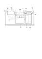
- the top view which shows a part of hydraulic excavator. Sectional drawing seen from the arrow BB direction in FIG.
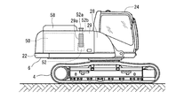
- the hydraulic excavator generally indicated by reference numeral 2 is a lower traveling body 4 that is a traveling device, an upper revolving body 6 that is provided on the lower traveling body 4 so as to be pivotable about a vertical axis, and is lifted in front of the upper revolving body 6.
- a work arm device 8 that is detachably mounted is generally constituted.
- the working arm device 8 is attached to the front side of the upper swing body 6 so as to be able to move up and down, the arm 12 attached to the tip of the boom 10 to be swingable, and attached to the tip of the arm 12 so as to be swingable.
- a work tool 14 a boom operating cylinder 16 for operating the boom 10 between the upper swing body 6 and the boom 10, an arm operating cylinder 18 for operating the arm 12 between the boom 10 and the arm 12, and an arm between 12 and the work tool 14, a work tool operating cylinder 20 for operating the work tool 14 is provided.
- the upper swing body 6 is swung with respect to the lower traveling body 4 so that the work arm device 8 attached to the front side of the upper swing body 6 so as to be able to move up and down performs excavation work of earth and sand. It has become.
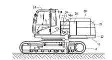
- the upper revolving unit 6 includes a revolving frame 22 that forms a framework structure, a cab 24 provided on the left front side of the revolving frame 22 along the left side of the work arm device 8, and a left side cover that covers the left side of the upper revolving unit 6. 26, 27 and right side covers 28, 29 covering the right side of the upper swing body 6 are provided.
- An opening 29a is provided on the front side of the right side cover 29, and cooling air is taken into the airframe from the opening 29a by a cooling fan 48 described later.
- the upper swing body 6 includes a maintenance deck 30 that is provided at the upper center portion of the upper swing body 6 and serves as a scaffold when an operator performs maintenance work.
- An elevating step 32 is provided inside the left side cover 26 along the back surface of the cab 24 so that the operator can elevate the maintenance deck 30 from the side of the upper swing body 6.
- a small handrail 34 is provided at the side of the elevating step 32 to assist the operator to move up and down.
- power batteries 36 are mounted in the space below the elevating step 32.
- the uppermost step portion 32a of the elevating step 32 is supported so as to be swingable upward and downward, and a pail can 38, a tool, and the like can be accommodated therein.
- the part where the engine 40 checks the tension of the belt of the engine 40, the part where the engine oil level gauge is checked, and the like are provided in the vicinity of the maintenance deck 30 below the maintenance deck 30.
- the exhaust gas treatment device 42 of the engine 40 is provided on the upper left side of the engine 40.
- the exhaust gas treatment device 42 includes a particulate matter removal filter that collects and removes particulate matter in the exhaust gas, a NOx purification device that purifies nitrogen oxide (NOx) using urea water, carbon monoxide, carbonization. It is composed of an aftertreatment device such as an oxidation catalyst for oxidizing and removing hydrogen.
- An air cleaner 44 of the engine 40 is provided on the upper right side of the engine 40 so that the longitudinal direction thereof is in the front-rear direction.
- the element of the air cleaner 44 is pulled out in the direction of arrow A and inserted in the direction opposite to the direction of arrow A.
- a partition wall member 46 is provided between the engine 40 and the air cleaner 44 to prevent heat transfer from the engine 40 to the air cleaner 44.
- the cooling fan 48 connected to the tip of the output shaft on one side of the engine 40 is provided on the right side of the engine 40, and the cooling package 50 is provided further to the right of the machine body than the cooling fan 48.
- the cooling package 50 is a package in which a plurality of heat exchangers such as a radiator, an oil cooler, and an intercooler are integrally formed.
- the cooling fan 48 is an axial fan that sucks air outside the machine body as cooling air from the opening 29 a of the right side cover 29 and distributes the air to the cooling package 50 and the engine 40.
- a urea water tank 52 for storing urea water as a reducing agent for the exhaust gas processing device 42 of the engine 40 is provided in front of the cooling package 50 and in the lower right of the maintenance deck 30. Is provided in the vicinity of the maintenance deck 30.
- a fuel tank 54 is provided in front of the urea water tank 52 and on the lower right side of the maintenance deck 30, and a fuel supply port 54 a is provided in the vicinity of the maintenance deck 30.
- a hydraulic oil tank 56 is provided at the lower left of the maintenance deck 30, and a filter 56 a for filtering the hydraulic oil is provided in the vicinity of the maintenance deck 30.
- One hood 58 is swingably opened and closed so as to cover the upper surfaces of the air cleaner 44, the cooling fan 48, the cooling package 50, etc., and covers the upper surfaces of the engine 40, the exhaust gas processing device 42, the hydraulic oil tank 56, and the like.
- the other hood 60 is provided so as to be able to swing open and close.
- the other hood 60 is positioned above the exhaust gas processing device 42, the hydraulic oil tank 56, etc., and has a left side 60a having substantially the same shape as the one hood 58, and a left side 60a above the engine 40.
- the two members of the right side portion 60b having a smaller size in the height direction and the longitudinal direction of the body are connected to each other.
- the upper swing body in the construction machine including the lower traveling body 4 and the upper swing body 6 that is swingably provided on the lower traveling body 4. 6, a maintenance deck 30 provided at the upper center of the center 6, and a lifting step 32 provided so as to move up and down from the side of the upper swing body 6 toward the maintenance deck 30.
- Equipment that requires maintenance is provided around, and a maintenance site for the equipment is provided in the vicinity of the maintenance deck 30.
- the equipment is separated from the engine 40 by an engine 40 provided below the maintenance deck 30 and a partition member 46 that blocks heat transfer from the engine 40.
- the maintenance deck 30 is positioned above the engine 40.
- an air cleaner 44 of the engine 40 provided at the rear, and the air cleaner 44 is provided such that an insertion / removal portion of the element faces the maintenance deck 30.
- the equipment includes a hydraulic oil tank 56 provided on the left side of the upper swing body 6, a fuel tank 54 provided on the right side of the upper swing body 6, and an exhaust gas of the engine 40 provided behind the fuel tank 54.
- a urea water tank 52 that stores urea water that is a reducing agent for the processing device 42, and includes a filter 56 a of the hydraulic oil tank 56, a fuel supply port 54 a of the fuel tank 54, and a water supply port 52 a of the urea water tank 52. It is provided in the vicinity of the maintenance deck 30.
- a plurality of maintenance operations such as tension check, exhaust gas treatment device 42 cleaning, air cleaner 44 element inspection, cleaning and replacement, urea water supply, fuel supply, and replacement of filter 56a of hydraulic oil tank 56, etc. This can be performed safely in a stable posture at the same place on the maintenance deck 30. As a result, the time required for the maintenance work can be shortened, and the maintenance workability can be improved.
- the upper swing body 6 includes a cab 24 provided on the left front side thereof, and the lifting step 32 is provided along the back surface of the cab 24.
- the elevating step 32 is provided along the back surface of the operator cab 24, a large-sized large projecting upward on the side of the elevating step 32 so as to be higher than the height of the operator's waist. Even if the handrail is not provided, the operator can safely ascend and descend to the maintenance deck 30 along the back surface of the cab 24. As a result, it is possible to solve the problem that the fixed portion of the handrail is damaged. In addition, since there is no need to provide a large handrail, the number of members and the cost of materials can be reduced.
- An opening 29a for taking cooling air into the machine body is provided on the front side of the right side cover 29 located on the side of the cooling package 50 and the urea water tank 52.
- the noise of the cooling fan 48 is less likely to leak to the outside of the fuselage compared to the case where an opening is provided at a position facing the cooling fan 48 across the cooling package 50 in the left-right direction of the upper swing body 6. Noise can be reduced. Further, since the cooling air passes around the urea water tank 52, it is possible to cool the urea water tank 52 that dislikes high temperature.
- the left side 60a of the one hood 58 and the other hood 60 have substantially the same shape, the one hood 58 and the left side 60a of the other hood 60 can be manufactured from the same mold. Can be reduced.
- the hood that covers the upper surface of the device behind the upper swing body 6 has a double hood configuration with one hood 58 and the other hood 60, the operating force required for opening and closing is greater than in the case of a single hood configuration. Therefore, the maintenance workability can be improved.
Landscapes
- Engineering & Computer Science (AREA)
- Mechanical Engineering (AREA)
- Chemical & Material Sciences (AREA)
- Combustion & Propulsion (AREA)
- Transportation (AREA)
- Mining & Mineral Resources (AREA)
- Civil Engineering (AREA)
- General Engineering & Computer Science (AREA)
- Structural Engineering (AREA)
- Life Sciences & Earth Sciences (AREA)
- Sustainable Development (AREA)
- Sustainable Energy (AREA)
- Component Parts Of Construction Machinery (AREA)
- Cooling, Air Intake And Gas Exhaust, And Fuel Tank Arrangements In Propulsion Units (AREA)
- Vehicle Step Arrangements And Article Storage (AREA)
Description
6:上部旋回体
24:運転室
30:メンテナンスデッキ
32:昇降ステップ
40:エンジン
42:排気ガス処理装置
44:エアクリーナ
46:隔壁部材
52:尿素水タンク
52a:給水口
54:燃料タンク
54a:給油口
56:作動油タンク
56a:フィルタ
Claims (4)
- 下部走行体と、該下部走行体上に旋回自在に設けられた上部旋回体とを備える建設機械において、
該上部旋回体の中央上部に設けられたメンテナンスデッキと、
該上部旋回体の側部から該メンテナンスデッキに向かって昇降するように設けられた昇降ステップとを備え、
該上部旋回体上で該メンテナンスデッキの周囲にはメンテナンスを要する機器類が設けられており、該機器類のメンテナンス部位が該メンテナンスデッキの近傍に設けられていることを特徴とする建設機械。 - 該機器類は、該メンテナンスデッキ後下方に設けられたエンジンと、
該エンジンからの熱の伝達を阻止する隔壁部材で該エンジンとは区分され該エンジンの上方に位置して該メンテナンスデッキ後方に設けられた該エンジンのエアクリーナとを含み、
該エアクリーナは、そのエレメントの挿脱部が該メンテナンスデッキに向くように設けられていることを特徴とする請求項1記載の建設機械。 - 該機器類は、該上部旋回体の左,右方向の一側に設けられた作動油タンクと、
該上部旋回体の左,右方向の他側に設けられた燃料タンクと、
該燃料タンクの後方に設けられ該エンジンの排気ガス処理装置用の還元剤である尿素水を貯留する尿素水タンクとを含み、
該作動油タンクのフィルタと、該燃料タンクの給油口と、該尿素水タンクの給水口とが該メンテナンスデッキの近傍に設けられていることを特徴とする請求項1又は2記載の建設機械。 - 該上部旋回体は、その左,右方向の一側に位置して該上部旋回体の前方に設けられた運転室を備え、
該昇降ステップは、該運転室の背面に沿って設けられていることを特徴とする請求項1から3までのいずれかに記載の建設機械。
Priority Applications (4)
| Application Number | Priority Date | Filing Date | Title |
|---|---|---|---|
| CN201380040583.4A CN104508212A (zh) | 2012-06-01 | 2013-04-10 | 建设机械 |
| EP13797580.1A EP2857595A4 (en) | 2012-06-01 | 2013-04-10 | CONSTRUCTION |
| US14/404,943 US20150259877A1 (en) | 2012-06-01 | 2013-04-10 | Construction machinery |
| KR20147036231A KR20150024851A (ko) | 2012-06-01 | 2013-04-10 | 건설기계 |
Applications Claiming Priority (2)
| Application Number | Priority Date | Filing Date | Title |
|---|---|---|---|
| JP2012-126261 | 2012-06-01 | ||
| JP2012126261A JP6122255B2 (ja) | 2012-06-01 | 2012-06-01 | 建設機械 |
Publications (1)
| Publication Number | Publication Date |
|---|---|
| WO2013179780A1 true WO2013179780A1 (ja) | 2013-12-05 |
Family
ID=49672988
Family Applications (1)
| Application Number | Title | Priority Date | Filing Date |
|---|---|---|---|
| PCT/JP2013/060815 Ceased WO2013179780A1 (ja) | 2012-06-01 | 2013-04-10 | 建設機械 |
Country Status (6)
| Country | Link |
|---|---|
| US (1) | US20150259877A1 (ja) |
| EP (1) | EP2857595A4 (ja) |
| JP (1) | JP6122255B2 (ja) |
| KR (1) | KR20150024851A (ja) |
| CN (1) | CN104508212A (ja) |
| WO (1) | WO2013179780A1 (ja) |
Cited By (1)
| Publication number | Priority date | Publication date | Assignee | Title |
|---|---|---|---|---|
| EP2886725A3 (en) * | 2013-12-20 | 2015-08-26 | Kobelco Construction Machinery Co., Ltd. | Construction machine |
Families Citing this family (10)
| Publication number | Priority date | Publication date | Assignee | Title |
|---|---|---|---|---|
| DE102013019448A1 (de) | 2013-11-21 | 2015-06-03 | Wirtgen Gmbh | Selbstfahrende Baumaschine |
| JP6303717B2 (ja) * | 2014-03-28 | 2018-04-04 | コベルコ建機株式会社 | 建設機械 |
| JP6317684B2 (ja) * | 2015-02-06 | 2018-04-25 | 日立建機株式会社 | 油圧ショベル |
| JP6632884B2 (ja) * | 2015-03-20 | 2020-01-22 | 住友建機株式会社 | 小旋回型ショベル |
| US10308108B2 (en) | 2015-03-30 | 2019-06-04 | Kubota Corporation | Working machine |
| JP6840557B2 (ja) * | 2017-02-06 | 2021-03-10 | 住友建機株式会社 | ショベル |
| US10947696B2 (en) | 2019-07-01 | 2021-03-16 | Caterpillar Inc. | Ingress/egress arrangement for machine |
| JP7503977B2 (ja) * | 2020-09-11 | 2024-06-21 | 株式会社小松製作所 | 装軌式搬送車両 |
| EP4137642B1 (de) * | 2021-08-19 | 2024-03-27 | Liebherr-Werk Bischofshofen GmbH | Arbeitsmaschine |
| JP2025068430A (ja) | 2023-10-16 | 2025-04-28 | コベルコ建機株式会社 | 作業機械 |
Citations (5)
| Publication number | Priority date | Publication date | Assignee | Title |
|---|---|---|---|---|
| JP2001234558A (ja) * | 2000-12-25 | 2001-08-31 | Komatsu Ltd | 建設機械の昇降用ラダー装置 |
| JP2002105982A (ja) * | 2000-09-29 | 2002-04-10 | Kobelco Contstruction Machinery Ltd | 建設機械の上部旋回体 |
| JP2004257333A (ja) | 2003-02-27 | 2004-09-16 | Shin Caterpillar Mitsubishi Ltd | エンジン吸気配管構造 |
| JP2006069365A (ja) | 2004-09-02 | 2006-03-16 | Shin Caterpillar Mitsubishi Ltd | 作業機械 |
| JP2011064133A (ja) * | 2009-09-17 | 2011-03-31 | Kobelco Contstruction Machinery Ltd | 建設機械 |
Family Cites Families (17)
| Publication number | Priority date | Publication date | Assignee | Title |
|---|---|---|---|---|
| US4067588A (en) * | 1976-02-09 | 1978-01-10 | Caterpillar Tractor Co. | Ladder assembly for construction vehicles |
| US4114716A (en) * | 1977-06-27 | 1978-09-19 | Caterpillar Tractor Co. | Housing apparatus |
| US4546844A (en) * | 1985-03-03 | 1985-10-15 | Dresser Industries, Inc. | Front wheel assist drive for a vehicle machine |
| JP3693480B2 (ja) * | 1998-01-09 | 2005-09-07 | コベルコ建機株式会社 | 油圧ショベルの上部旋回体 |
| AU2007205618B2 (en) * | 2006-01-12 | 2010-01-28 | Hitachi Construction Machinery Co., Ltd. | Construction machine inspection history information management system |
| JP4915157B2 (ja) * | 2006-07-12 | 2012-04-11 | コベルコ建機株式会社 | 建設機械 |
| JP4270239B2 (ja) * | 2006-08-11 | 2009-05-27 | コベルコ建機株式会社 | 建設機械 |
| JP4725476B2 (ja) * | 2006-10-10 | 2011-07-13 | コベルコ建機株式会社 | 建設機械 |
| JP5164414B2 (ja) * | 2007-04-04 | 2013-03-21 | 日立建機株式会社 | 建設機械のエンジンルーム装置 |
| DE102007023568B3 (de) * | 2007-05-21 | 2008-12-11 | Komatsu Ltd. | Bedienpersonsitz für eine Baumaschine und damit versehene Kabine und Baumaschine |
| US8215434B2 (en) * | 2007-06-26 | 2012-07-10 | Hitachi Construction Machinery Co., Ltd. | Construction machine |
| JP5172381B2 (ja) * | 2008-02-22 | 2013-03-27 | 日立建機株式会社 | 建設機械 |
| JP4925351B2 (ja) * | 2008-02-27 | 2012-04-25 | キャタピラー エス エー アール エル | 建設機械における化粧カバー構造 |
| JP5309976B2 (ja) * | 2008-12-25 | 2013-10-09 | コベルコ建機株式会社 | 作業機械 |
| JP5152027B2 (ja) * | 2009-02-13 | 2013-02-27 | コベルコ建機株式会社 | ツールボックス構造 |
| JP2011099284A (ja) * | 2009-11-09 | 2011-05-19 | Caterpillar Sarl | ドア装置 |
| JP5118116B2 (ja) * | 2009-11-11 | 2013-01-16 | コベルコ建機株式会社 | 建設機械 |
-
2012
- 2012-06-01 JP JP2012126261A patent/JP6122255B2/ja active Active
-
2013
- 2013-04-10 US US14/404,943 patent/US20150259877A1/en not_active Abandoned
- 2013-04-10 WO PCT/JP2013/060815 patent/WO2013179780A1/ja not_active Ceased
- 2013-04-10 CN CN201380040583.4A patent/CN104508212A/zh active Pending
- 2013-04-10 KR KR20147036231A patent/KR20150024851A/ko not_active Withdrawn
- 2013-04-10 EP EP13797580.1A patent/EP2857595A4/en not_active Withdrawn
Patent Citations (5)
| Publication number | Priority date | Publication date | Assignee | Title |
|---|---|---|---|---|
| JP2002105982A (ja) * | 2000-09-29 | 2002-04-10 | Kobelco Contstruction Machinery Ltd | 建設機械の上部旋回体 |
| JP2001234558A (ja) * | 2000-12-25 | 2001-08-31 | Komatsu Ltd | 建設機械の昇降用ラダー装置 |
| JP2004257333A (ja) | 2003-02-27 | 2004-09-16 | Shin Caterpillar Mitsubishi Ltd | エンジン吸気配管構造 |
| JP2006069365A (ja) | 2004-09-02 | 2006-03-16 | Shin Caterpillar Mitsubishi Ltd | 作業機械 |
| JP2011064133A (ja) * | 2009-09-17 | 2011-03-31 | Kobelco Contstruction Machinery Ltd | 建設機械 |
Non-Patent Citations (1)
| Title |
|---|
| See also references of EP2857595A4 |
Cited By (2)
| Publication number | Priority date | Publication date | Assignee | Title |
|---|---|---|---|---|
| EP2886725A3 (en) * | 2013-12-20 | 2015-08-26 | Kobelco Construction Machinery Co., Ltd. | Construction machine |
| US9428882B2 (en) | 2013-12-20 | 2016-08-30 | Kobelco Construction Machinery Co., Ltd. | Construction machine |
Also Published As
| Publication number | Publication date |
|---|---|
| KR20150024851A (ko) | 2015-03-09 |
| JP2013249670A (ja) | 2013-12-12 |
| US20150259877A1 (en) | 2015-09-17 |
| CN104508212A (zh) | 2015-04-08 |
| JP6122255B2 (ja) | 2017-04-26 |
| EP2857595A4 (en) | 2016-01-20 |
| EP2857595A1 (en) | 2015-04-08 |
Similar Documents
| Publication | Publication Date | Title |
|---|---|---|
| JP6122255B2 (ja) | 建設機械 | |
| CN101542045B (zh) | 工程机械 | |
| CN104114775B (zh) | 液压挖掘机 | |
| JP5442829B1 (ja) | 油圧ショベル | |
| CN102781705B (zh) | 储油罐以及建设车辆 | |
| JP5501537B1 (ja) | 還元剤タンク、及び作業車両 | |
| JP6385381B2 (ja) | 建設機械 | |
| JP5867485B2 (ja) | 建設機械 | |
| JP2013002082A (ja) | 建設機械 | |
| JP2012237232A (ja) | 建設機械 | |
| CN104631539A (zh) | 工程机械 | |
| JP2008045297A (ja) | 建設機械 | |
| JP5782971B2 (ja) | 建設機械 | |
| JP6594237B2 (ja) | 建設機械 | |
| JP7025307B2 (ja) | 建設機械 | |
| JP6286344B2 (ja) | 建設機械 | |
| JP2000204595A (ja) | 建設機械のエンジン点検用ステップ装置 | |
| JP2010065717A (ja) | 作動油タンクおよびそれを備えた建設機械 | |
| JP6704871B2 (ja) | 建設機械 | |
| JP7507664B2 (ja) | 建設機械 | |
| US10961688B2 (en) | Construction machine | |
| JP2021098985A (ja) | 作業機械 |
Legal Events
| Date | Code | Title | Description |
|---|---|---|---|
| 121 | Ep: the epo has been informed by wipo that ep was designated in this application |
Ref document number: 13797580 Country of ref document: EP Kind code of ref document: A1 |
|
| NENP | Non-entry into the national phase |
Ref country code: DE |
|
| WWE | Wipo information: entry into national phase |
Ref document number: 2013797580 Country of ref document: EP |
|
| ENP | Entry into the national phase |
Ref document number: 20147036231 Country of ref document: KR Kind code of ref document: A |
|
| WWE | Wipo information: entry into national phase |
Ref document number: 14404943 Country of ref document: US |