WO2013179790A1 - 列車制御装置 - Google Patents
列車制御装置 Download PDFInfo
- Publication number
- WO2013179790A1 WO2013179790A1 PCT/JP2013/061229 JP2013061229W WO2013179790A1 WO 2013179790 A1 WO2013179790 A1 WO 2013179790A1 JP 2013061229 W JP2013061229 W JP 2013061229W WO 2013179790 A1 WO2013179790 A1 WO 2013179790A1
- Authority
- WO
- WIPO (PCT)
- Prior art keywords
- train
- time
- travel
- travel plan
- station
- Prior art date
- Legal status (The legal status is an assumption and is not a legal conclusion. Google has not performed a legal analysis and makes no representation as to the accuracy of the status listed.)
- Ceased
Links
Images


Classifications
-
- B—PERFORMING OPERATIONS; TRANSPORTING
- B61—RAILWAYS
- B61L—GUIDING RAILWAY TRAFFIC; ENSURING THE SAFETY OF RAILWAY TRAFFIC
- B61L15/00—Indicators provided on the vehicle or train for signalling purposes
- B61L15/0058—On-board optimisation of vehicle or vehicle train operation
-
- B—PERFORMING OPERATIONS; TRANSPORTING
- B61—RAILWAYS
- B61L—GUIDING RAILWAY TRAFFIC; ENSURING THE SAFETY OF RAILWAY TRAFFIC
- B61L27/00—Central railway traffic control systems; Trackside control; Communication systems specially adapted therefor
- B61L27/10—Operations, e.g. scheduling or time tables
- B61L27/12—Preparing schedules
-
- B—PERFORMING OPERATIONS; TRANSPORTING
- B61—RAILWAYS
- B61L—GUIDING RAILWAY TRAFFIC; ENSURING THE SAFETY OF RAILWAY TRAFFIC
- B61L15/00—Indicators provided on the vehicle or train for signalling purposes
- B61L15/0062—On-board target speed calculation or supervision
-
- B—PERFORMING OPERATIONS; TRANSPORTING
- B61—RAILWAYS
- B61L—GUIDING RAILWAY TRAFFIC; ENSURING THE SAFETY OF RAILWAY TRAFFIC
- B61L25/00—Recording or indicating positions or identities of vehicles or trains or setting of track apparatus
- B61L25/02—Indicating or recording positions or identities of vehicles or trains
- B61L25/021—Measuring and recording of train speed
-
- B—PERFORMING OPERATIONS; TRANSPORTING
- B61—RAILWAYS
- B61L—GUIDING RAILWAY TRAFFIC; ENSURING THE SAFETY OF RAILWAY TRAFFIC
- B61L25/00—Recording or indicating positions or identities of vehicles or trains or setting of track apparatus
- B61L25/02—Indicating or recording positions or identities of vehicles or trains
- B61L25/025—Absolute localisation, e.g. providing geodetic coordinates
-
- B—PERFORMING OPERATIONS; TRANSPORTING
- B61—RAILWAYS
- B61L—GUIDING RAILWAY TRAFFIC; ENSURING THE SAFETY OF RAILWAY TRAFFIC
- B61L25/00—Recording or indicating positions or identities of vehicles or trains or setting of track apparatus
- B61L25/02—Indicating or recording positions or identities of vehicles or trains
- B61L25/026—Relative localisation, e.g. using odometer
-
- B—PERFORMING OPERATIONS; TRANSPORTING
- B61—RAILWAYS
- B61L—GUIDING RAILWAY TRAFFIC; ENSURING THE SAFETY OF RAILWAY TRAFFIC
- B61L27/00—Central railway traffic control systems; Trackside control; Communication systems specially adapted therefor
- B61L27/10—Operations, e.g. scheduling or time tables
- B61L27/14—Following schedules
-
- B—PERFORMING OPERATIONS; TRANSPORTING
- B61—RAILWAYS
- B61L—GUIDING RAILWAY TRAFFIC; ENSURING THE SAFETY OF RAILWAY TRAFFIC
- B61L15/00—Indicators provided on the vehicle or train for signalling purposes
- B61L15/0018—Communication with or on the vehicle or train
- B61L15/0027—Radio-based, e.g. using GSM-R
-
- B—PERFORMING OPERATIONS; TRANSPORTING
- B61—RAILWAYS
- B61L—GUIDING RAILWAY TRAFFIC; ENSURING THE SAFETY OF RAILWAY TRAFFIC
- B61L3/00—Devices along the route for controlling devices on the vehicle or train, e.g. to release brake or to operate a warning signal
- B61L3/16—Continuous control along the route
- B61L3/22—Continuous control along the route using magnetic or electrostatic induction; using electromagnetic radiation
- B61L3/221—Continuous control along the route using magnetic or electrostatic induction; using electromagnetic radiation using track circuits
Definitions
- Embodiments of the present invention relate to a train control device.
- ATO automatic train operation
- the travel plan in ATO is calculated so that the travel time of the travel plan approaches the predetermined travel time determined for each station according to the route data or the vehicle model data, and the arrival time of the next station is taken into consideration. It was not created. Therefore, in the above-described prior art, when the departure is delayed from the diamond, the arrival at the next station may be delayed from the diamond.
- the train control device of the embodiment includes a detection unit that detects the current position and speed of the own train, a time measuring unit that measures the current time, and a diagram that inputs diagram data including the scheduled arrival time of the own train at each station on the route.
- An input unit a target travel time obtained by subtracting the current time measured from the estimated arrival time of the next station included in the input diagram data, the detected current position, the detected speed, and the own train
- a calculation unit that calculates a travel plan to the next station based on the driving characteristics and route conditions.
- FIG. 1 is a block diagram illustrating a configuration of a train control device according to the first embodiment.
- FIG. 2 is a flowchart illustrating an example of the operation of the train control device according to the first embodiment.
- FIG. 3 is a conceptual diagram illustrating a travel plan.
- FIG. 4 is a conceptual diagram illustrating a travel plan when there is a passing station.
- FIG. 5 is a conceptual diagram illustrating a travel plan when there is a passing station.
- FIG. 6 is a conceptual diagram illustrating a travel plan when there is a passing station.
- FIG. 7 is a block diagram illustrating a configuration of the train control device according to the second embodiment.
- FIG. 8 is a conceptual diagram illustrating the relationship between the brake pattern estimated from the speed limit and the travel plan.
- FIG. 9 is a conceptual diagram illustrating the recalculation of the travel plan when there is an interval from the preceding train.
- FIG. 1 is a block diagram illustrating a configuration of a train control device 1 according to the first embodiment.
- the train T is provided with a train control device 1 and a drive / brake control device 3 that drives / brakes the train T based on a power running command and a brake command from the train control device 1.
- the train T travels on the rail R by driving / braking the wheels 2 by the driving / braking control device 3.
- the drive / brake control device 3 includes an inverter for controlling the motor and a brake control device for cooperatively controlling the idling by the brake device and the electric control by the motor.
- the train control device 1 includes a speed / position detection unit 10, an ATC on-board device 20 (Automatic Train Control), an ATO device 30, a diagram input unit 31, a database 32, a time measuring unit 33, and a display device 60. It is a configuration.
- the speed / position detection unit 10 detects the speed of the train T traveling on the rail R and the position on the route. Specifically, the speed / position detection unit 10 detects the speed of the train T from the output value of the TG 12 (tacho generator) interlocked with the rotation of the wheels 2.
- the TG 12 may be a PG (pulse generator) that works in conjunction with the rotation of the wheel 2.
- the speed / position detection unit 10 also determines the current position of the train T on the route based on the travel distance obtained by integrating the speed of the train T and the signal from the ground element 13 received by the vehicle upper element 11. Is detected.
- the speed of the train T detected by the speed / position detector 10 and the current position of the train T are output to the ATC on-board device 20 and the ATO device 30 as speed / position information.
- the ATC on-board device 20 receives information notified from the ATC ground device 22 as an analog signal via the track circuit 23 of the rail R by the power receiver 21.
- the ATC on-board device 20 outputs a brake command to the drive / brake control device 3 based on the information notified from the ATC ground device 22 and the speed of the train T.
- the information notified from the ATC ground device 22 includes a signal display speed indicating a speed limit (display speed) in a closed section where the train T is present.
- the ATC on-board device 20 compares the signal display speed notified from the ATC ground device 22 with the speed of the train T.
- the ATC on-board device 20 outputs a brake command to the drive / brake control device 3 when the speed of the train T exceeds the signal display speed. Further, the ATC on-board device 20 outputs the signal display speed received by the power receiver 21 to the ATO device 30.
- the ATO device 30 outputs a power running command and a brake command to the drive / brake control device 3 under the ATC on-board device 20. Specifically, the ATO device 30 exceeds the signal display speed output from the ATC on-board device 20 based on the speed of the train T detected by the speed / position detection unit 10 and the current position of the train T.
- a control command (notch command) such as a power running command and a brake command is output to the drive / brake control device 3 so that the train T travels in a range that does not exist and stops at a predetermined position of the station.
- the ATO device 30 calculates a travel plan until the train T having the current position and speed detected by the speed / position detection unit 10 reaches the next station according to the operation characteristics and route conditions of the own train (details will be described later). To do).
- This travel plan is data that defines power running, coasting and braking sections and curves for stopping the train T at a target position of the next stop station for a predetermined travel time.
- the ATO device 30 operates the train T based on the calculated travel plan.
- the ATO device 30 In the case of automatic operation, the ATO device 30 outputs a power running command and a brake command to the drive / brake control device 3 based on the travel plan. Thereby, the train control device 1 automatically operates the train T according to the travel plan.
- the ATO device 30 displays the target speed based on the travel plan on the display device 60 installed on the cab. Based on the target speed displayed on the display device 60, the driver operates a master controller (not shown) to manually operate the train T according to the travel plan.
- the diamond input unit 31 receives input of diamond data including the scheduled arrival (passing) time of the train T at each station on the route.
- the input of diamond data is accepted by wireless communication via the communication device 40, reading of data written in the memory unit 52 of the work card 51 which is an IC card connected via the I / F device 50, or the like.
- the diamond data input by the diamond input unit 31 is recorded as operation conditions on the database 32.
- the schedule data of each train that operates on the route is managed by the operation management center 41.
- This diamond data is notified to the station management device 42 on the route of the train T via the communication line.
- the train T diagram data notified from the operation management center 41 is wirelessly communicated to the communication device 40 of the train T, or the work card 51 is inserted into the I / F device 50 by the driver at the start of operation.
- the train T is notified by writing to the memory unit 52.
- the communication device 40 is a device that performs wireless communication with the station management device 42, reception of GPS signals, and the like.
- the communication device 40 receives the diagram data notified by radio from the station management device 42 and outputs it to the diagram input unit 31.
- the I / F device 50 is a card reader or the like, and reads the diamond data written in the memory unit 52 of the work card 51 and outputs it to the diamond input unit 31.
- the database 32 includes route conditions (gradient, curvature, speed limit, etc.), operating conditions (stop target position of each station, schedule data including passage or arrival time at each station), vehicle performance (vehicle weight, acceleration / deceleration performance, etc.) Data necessary for the operation of the train T, such as train operating characteristics, is stored.
- the database 32 may be a hard disk mounted in the train T, an IC card carried by the driver, or the like. In the case of an IC card, the database 32 can be used by being inserted into the I / F device 50 at the start of operation.
- the timekeeping unit 33 has an RTC (Real Time Clock) function and measures the current time.
- the current time measured by the time measuring unit 33 is output to the ATO device 30. It is assumed that the current time measured by the time measuring unit 33 is synchronized with the current time referred to when creating the diagram data on the operation management center 41 side. Specifically, in the operation management center 41 and the train T, the current time is synchronized with the GPS time included in the GPS signal. Alternatively, the current time may be synchronized with the operation management center 41 side by wireless communication when the station stops.
- RTC Real Time Clock
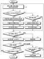
- FIG. 2 is a flowchart illustrating an example of the operation of the train control device 1 according to the first embodiment.
- the ATO device 30 acquires the current position and current speed of the train T from the speed / position detector 10 and the current time from the timer 33 (S1). Next, the ATO device 30 determines whether or not there is a travel plan to the next station (S2). Here, when the vehicle is stopped before departure or when the next station is updated in S14, the travel plan to the next station has not been calculated, and thus there is no travel plan. In addition, a travel plan to the next station is calculated at the time of departure, and when the travel plan is being calculated, the travel plan is present.
- the ATO device 30 When there is no travel plan in S2, the ATO device 30 refers to the diagram data included in the operation conditions input by the diagram input unit 31 and recorded in the database 32, and acquires the scheduled arrival (passing) time of the next station. (S3). Next, the ATO device 30 calculates a target travel time obtained by subtracting the current time from the scheduled arrival (passing) time of the next station (S4), and based on the route conditions and vehicle performance recorded in the database 32, the target travel is calculated. A travel plan with a travel time close to the time is calculated (S5). As a result, the ATO device 30 travels automatically or manually according to the calculated travel plan.
- FIG. 3 is a conceptual diagram illustrating the travel plan P.
- the ATO device 30 is a known method for predicting the traveling behavior of the train T using a dynamic train model based on the vehicle performance within the range of the speed limit in the route condition recorded in the database 32, for example, Using the method described in Japanese Patent Application No. Hei 4-284684, traveling with the powering, coasting and braking sections and curves determined so that the traveling time of the traveling plan is close to the target traveling time between stations.
- the plan P is calculated.
- the ATO device 30 when the travel time of the travel plan P calculated as described above deviates from the target travel time, that is, even if the travel time of the calculated travel plan P is close to the target travel time, the ATO device 30 For example, if it does not reach a coincidence due to travel at a lower speed than the travel plan due to delays in departure from the station or driver operations between stations, there is a possibility that the next station may not arrive as scheduled.
- a warning screen is displayed on the display device 60 to notify the driver.
- a delay time indicating a delay from the diagram in the travel time of the travel plan P and an estimated arrival time are displayed on the display device 60 to notify the driver. This notification may be performed by a warning sound from a speaker or the like, or may be notified to the station management device 42 and the operation management center 41 via the communication device 40 and notified to an operator other than the driver.
- the ATO device 30 determines whether or not it is necessary to re-plan the travel plan (S6). Specifically, when the speed of the train T detected by the speed / position detector 10 or the time by the timer 33 deviates from the travel plan by a threshold or more, the signal display speed (speed limit) is changed in the analog ATC. When it becomes, it determines with the re-planning of a travel plan being required when the space
- the ATO device 30 increases the signal display speed notified from the ATC on-board device 20 due to an interval from the preceding train, and matches the speed limit on the route condition at the current position during traveling. Assume that a predetermined time has passed since the start of the operation, and it is determined that the distance from the preceding train is sufficiently large, and replanning is necessary.
- the ATO device 30 calculates a target travel time obtained by subtracting the current time for replanning from the scheduled arrival (passing) time of the next station (S7), as in S4 and S5. Based on the route conditions and vehicle performance recorded in the database 32, a travel plan is calculated that has a travel time close to the target travel time (S8). As a result, the ATO device 30 travels in an automatic operation or a manual operation based on the travel plan calculated as requiring re-planning. Therefore, for example, even when approaching the preceding train between stations, if the distance from the preceding train is free again, a new travel plan is calculated, so that there is no deviation from the schedule. Can continue.
- the ATO device 30 determines whether there is an approaching preceding train (S9). Specifically, the ATO device 30 compares the speed limit on the route condition at the current position during traveling with the signal display speed notified from the ATC on-board device 20, and signals that the vehicle has approached the preceding train If there is a decrease in the displayed speed, there is an approaching preceding train. It is assumed that there is an interval from the preceding train when a predetermined time has elapsed since the signal display speed increased and the speed limit on the route condition was reached.
- the ATO device 30 continues traveling according to the travel plan (S10). Moreover, when approaching a preceding train in S9, the ATO apparatus 30 performs the deceleration control which decelerated from the travel plan so that the ATO apparatus 30 may open the space
- the ATO device 30 uses the speed / position information from the speed / position detection unit 10 as the next train T. It is determined whether or not the station (stop station) has arrived (S15). Specifically, it is determined that the train T has arrived at the stop station when the train T reaches the stop target position of the stop station. In S15, when it is arrival at the next station (stop station), the ATO device 30 ends the process for traveling from the departure station to the stop station. If the ATO device 30 has not arrived at the next station, the ATO device 30 returns the process to S1 and continues the process for traveling from the departure station to the stop station.
- FIG. 4 to 6 are conceptual diagrams illustrating travel plans P1 to P5 when there are passing stations STa to STd.
- traveling plans P1 to P5 are calculated for each passing station according to the above-described flowchart, and the train T is traveled.
- the stop target position M1 is a leading position when the train T stops at each station, and is a position that serves as a reference for the scheduled arrival (passing) time of the train T at each station.
- the approach start position M2 shows the position where the train T starts entering each station.
- the target travel time is set.
- a travel plan P1 that passes through the passing station STa at a predetermined speed limit is calculated as 0:02:03.
- the vehicle travels according to the travel plan P1 in the range from the stop target position M1 of the station ST1 to the stop target position M1 of the passing station STa.
- the travel plan P2 of the target travel time is calculated based on the time when the vehicle has sufficiently approached the transit station STa (arrival at the entry start position M2) and the scheduled transit time 12:04:45 of the transit station STb. The Therefore, as shown in FIG.
- traveling according to the traveling plan P2 is performed in the range from the entry start position M2 of the passing station STa to the stop target position M1 of the passing station STb.
- the travel plan P1 travels until the travel plan P2 is calculated until the travel start position M2 is reached so that the travel plan is not interrupted.
- the travel plan P2 is switched so that travel is performed.
- travel plans P3 to P5 of travel times based on the time of arrival at the passing stations STb to STd and the scheduled passage (arrival) time of the next station are calculated, and the travel plans P3 to P5 are followed. Running.
- FIG. 7 is a block diagram showing the configuration of the train control device 1a according to the second embodiment.
- the ATC on-board device 20a receives information notified from the ATC ground device 22a as a digital signal via the track circuit 23 of the rail R by the power receiver 21a.
- the ATC on-board device 20a outputs a brake command to the drive / brake control device 3 based on the information notified from the ATC ground device 22a and the speed of the train T.
- the amount of information that can be notified from the ATC ground device 22a can be larger than that of the analog ATC, and the information notified from the ATC ground device 22a includes the signal display speed in the block section where the train T is present, The number of open sections is included.
- the number of open sections is the number of closed sections between the closed section in which the preceding train is traveling and the closed section in which the train T is traveling.
- the ATC on-board device 20 outputs the signal display speed and the number of open sections received by the power receiver 21 a to the ATO device 30.
- the travel plan P is calculated by the ATO device 30 in the same manner as described with reference to FIG. 2 in the first embodiment.
- the ATO device 30 is on the ATC vehicle estimated based on the speed limit in the route condition.
- the travel plan P is adjusted so that the travel speed of the train T approaches the brake pattern (intensifies the deceleration at the time of deceleration) until it matches the brake pattern of the device 20a.
- the ATO device 30 is placed in the foreground when the travel according to the travel plan P gets too early.
- the travel plan P is adjusted so that the train T is decelerated at the position (the deceleration at the time of deceleration is weakened (returned back)).
- FIG. 8 is a conceptual diagram illustrating the relationship between the brake pattern BP and the travel plan P estimated from the speed limit.
- the deceleration start position is brought closer to the brake pattern BP, and the train T travels to the brake pattern BP.
- the travel time can be shortened by setting the travel plan Pb to approach the speed.
- the travel plan P can be made longer by setting the travel plan Pa to the deceleration start position in front of the brake pattern BP. In this travel plan Pa, the ride comfort is improved by mitigating sudden deceleration compared to the travel plan Pb.
- the ATO device 30 determines whether or not the distance from the preceding train when there is an approaching preceding train is greater than or equal to a predetermined interval (FIG. 2, S9). Do. Therefore, it is possible to travel according to the distance from the preceding train.
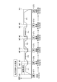
- FIG. 9 is a conceptual diagram illustrating the recalculation of the travel plan when there is an interval from the preceding train T1.
- the train T traveling in the stations ST1 and ST2 according to the travel plan P10 approaches the preceding train T1
- the train T decelerates due to the contact with the brake pattern BP1 by the preceding train T1.
- the brake pattern BP1 also advances as the preceding train T1 advances, so that no contact with the brake pattern BP1 occurs. A distance will occur.
- the ATO device 30 calculates the new travel plan P20 and travels to the station ST2 when the number of open sections is such that deceleration by the brake pattern BP does not occur, so that the preceding train T1 While maintaining the distance, it is possible to continue operation with less deviation from the diamond.
- the present invention is not limited to the above-described embodiment as it is, and can be embodied by modifying the constituent elements without departing from the scope of the invention in the implementation stage.
- various inventions can be formed by appropriately combining a plurality of constituent elements disclosed in the embodiment. For example, some components may be deleted from all the components shown in the embodiment. Furthermore, the constituent elements over different embodiments may be appropriately combined.
Landscapes
- Engineering & Computer Science (AREA)
- Mechanical Engineering (AREA)
- Electric Propulsion And Braking For Vehicles (AREA)
- Train Traffic Observation, Control, And Security (AREA)
Abstract
Description
図1は、第1の実施形態にかかる列車制御装置1の構成を示すブロック図である。図1に示すように、列車Tには、列車制御装置1と、列車制御装置1からの力行指令やブレーキ指令に基づいて列車Tを駆動/制動する駆動・制動制御装置3が設置されている。列車Tは、駆動・制動制御装置3により車輪2が駆動/制動されてレールR上を走行する。なお、駆動・制動制御装置3は、モータを制御するためのインバータ及びブレーキ装置による空制とモータによる電制を協調制御するためのブレーキ制御装置とを含んでいる。
上述した第1の実施形態ではアナログATCを用いた場合を例示したが、第2の実施形態では、デジタルATCを用いた構成を例示する。
Claims (7)
- 自列車の現在位置及び速度を検出する検出部と、
現在時刻を計時する計時部と、
路線上の各駅における自列車の到着予定時刻を含むダイヤデータを入力するダイヤ入力部と、
前記入力されたダイヤデータに含まれる次駅の到着予定時刻から前記計時された現在時刻を差し引いた目標走行時間と、前記検出された現在位置、前記検出された速度、及び自列車の運転特性及び路線条件に基づいて次駅に至るまでの走行計画を算出する算出部と、
を備える列車制御装置。 - 前記算出部は、前記路線条件に基づいたATC(Automatic Train Control)のブレーキパターンと接触しない範囲内で、自列車の走行速度を前記ブレーキパターンに近づけることで前記走行時間を短くして、前記目標走行時間に近づく前記走行時間の走行計画を算出する、
請求項1に記載の列車制御装置。 - 前記算出部は、前記路線条件に基づいたATCによるブレーキパターンと接触しない範囲内で、より手前に自列車の減速を行うことで前記走行時間を長くして、前記目標走行時間に近づく前記走行時間の走行計画を算出する、
請求項1に記載の列車制御装置。 - 前記ダイヤデータは、路線上の通過駅における自列車の通過予定時刻を含み、
前記算出部は、前記通過駅ごとに、前記入力されたダイヤデータに含まれる次駅の通過又は到着予定時刻から前記計時された現在時刻を差し引いた目標走行時間に近づく走行時間の前記走行計画を算出する、
請求項1に記載の列車制御装置。 - 前記目標走行時間からずれた走行時間の走行計画が算出された場合は警告を報知する報知部を更に備える、
請求項1に記載の列車制御装置。 - 前記算出部は、前記走行計画に従った走行時に先行列車の接近による減速が生じた場合は、前記先行列車と自列車との間隔が所定の間隔以上空いたところで、前記走行計画を再算出する、
請求項1に記載の列車制御装置。 - 前記先行列車と自列車との間の閉塞区間数を示す開通区間数を受信する受信部を更に備え、
前記算出部は、前記開通区間数が所定値以上となったところで、前記走行計画を再算出する、
請求項6に記載の列車制御装置。
Priority Applications (3)
| Application Number | Priority Date | Filing Date | Title |
|---|---|---|---|
| CN201380028205.4A CN104379396B (zh) | 2012-05-30 | 2013-04-15 | 列车控制装置 |
| BR112014028228A BR112014028228A2 (pt) | 2012-05-30 | 2013-04-15 | dispositivo de controle de trem |
| EP13796521.6A EP2857255A4 (en) | 2012-05-30 | 2013-04-15 | ZUGSTEUERUNGSVORRICHTUNG |
Applications Claiming Priority (2)
| Application Number | Priority Date | Filing Date | Title |
|---|---|---|---|
| JP2012-123725 | 2012-05-30 | ||
| JP2012123725A JP5944229B2 (ja) | 2012-05-30 | 2012-05-30 | 列車制御装置 |
Publications (1)
| Publication Number | Publication Date |
|---|---|
| WO2013179790A1 true WO2013179790A1 (ja) | 2013-12-05 |
Family
ID=49671229
Family Applications (1)
| Application Number | Title | Priority Date | Filing Date |
|---|---|---|---|
| PCT/JP2013/061229 Ceased WO2013179790A1 (ja) | 2012-05-30 | 2013-04-15 | 列車制御装置 |
Country Status (6)
| Country | Link |
|---|---|
| US (1) | US20130325224A1 (ja) |
| EP (1) | EP2857255A4 (ja) |
| JP (1) | JP5944229B2 (ja) |
| CN (1) | CN104379396B (ja) |
| BR (1) | BR112014028228A2 (ja) |
| WO (1) | WO2013179790A1 (ja) |
Families Citing this family (32)
| Publication number | Priority date | Publication date | Assignee | Title |
|---|---|---|---|---|
| WO2014002753A1 (ja) * | 2012-06-29 | 2014-01-03 | 三菱電機株式会社 | 列車制御装置 |
| EP3138755B1 (en) * | 2014-04-28 | 2019-05-08 | Hitachi, Ltd. | A train operation support system |
| JP6382618B2 (ja) * | 2014-07-29 | 2018-08-29 | 株式会社東芝 | 列車制御装置 |
| EP2979952B1 (en) * | 2014-07-29 | 2017-02-01 | Mitsubishi Electric R&D Centre Europe B.V. | Method for reducing the delay of a rail vehicle to reach a destination |
| CN107428351B (zh) * | 2015-02-27 | 2019-01-25 | 三菱电机株式会社 | 道口控制装置、车上控制系统、道口控制系统及道口阻断时间缩短方法 |
| US10457307B2 (en) | 2016-06-08 | 2019-10-29 | Westinghouse Air Brake Technologies Corporation | Wireless crossing activation system and method |
| US10654500B2 (en) * | 2015-06-12 | 2020-05-19 | Westinghouse Air Brake Technologies Corporation | Arrival time and location targeting system and method |
| CN105109522B (zh) * | 2015-07-08 | 2017-03-01 | 中车南京浦镇车辆有限公司 | 一种动车组ato自动驾驶控制电路 |
| JP2017022853A (ja) * | 2015-07-09 | 2017-01-26 | 株式会社東芝 | 列車制御装置 |
| CN105774848A (zh) * | 2016-02-26 | 2016-07-20 | 苏州富欣智能交通控制有限公司 | 轨交列车到站时间预测方法 |
| JP6696688B2 (ja) * | 2016-03-03 | 2020-05-20 | 株式会社東芝 | 列車制御装置 |
| JP2017165237A (ja) * | 2016-03-16 | 2017-09-21 | 株式会社日立製作所 | 列車運転支援システム |
| DE102016204597A1 (de) * | 2016-03-21 | 2017-09-21 | Siemens Aktiengesellschaft | ATO-Einrichtung, Schienenfahrzeug und Verfahren zum automatisierten Fahren eines Schienenfahrzeugs |
| US9925993B2 (en) | 2016-04-19 | 2018-03-27 | New York Air Brake, LLC | Speed profiling for locomotive display and event recorder |
| US11433933B2 (en) * | 2016-08-04 | 2022-09-06 | Mitsubishi Electric Corporation | Ground base device, unmanned operation system, operation system, and unmanned operation method |
| US10279823B2 (en) * | 2016-08-08 | 2019-05-07 | General Electric Company | System for controlling or monitoring a vehicle system along a route |
| JP6714710B2 (ja) * | 2016-10-03 | 2020-06-24 | 株式会社京三製作所 | 車上装置及び非常ブレーキ制御方法 |
| CN107215361B (zh) * | 2017-06-09 | 2018-12-28 | 湖南中车时代通信信号有限公司 | 基于列车运行监控系统的列车时刻表显示装置 |
| WO2018229986A1 (ja) * | 2017-06-16 | 2018-12-20 | 三菱電機株式会社 | 車両起動システム、遠隔制御システム、列車統合管理システム、自動列車制御装置および車両起動方法 |
| CN109305197B (zh) * | 2017-07-26 | 2020-08-25 | 比亚迪股份有限公司 | 列车控制方法、系统和车载控制器 |
| JP6580107B2 (ja) * | 2017-11-02 | 2019-09-25 | 本田技研工業株式会社 | 車両制御装置 |
| JP7067952B2 (ja) * | 2018-02-16 | 2022-05-16 | 株式会社東芝 | 運転曲線作成装置、運転支援装置および運転制御装置 |
| CN109398426B (zh) * | 2018-09-19 | 2020-06-16 | 中南大学 | 一种定时条件下基于离散蚁群算法的节能驾驶策略寻优方法 |
| CN111376949B (zh) * | 2018-12-29 | 2022-02-15 | 交控科技股份有限公司 | 一种计算ato准点曲线的调整速度的方法 |
| CN109649418A (zh) | 2019-01-29 | 2019-04-19 | 中车长春轨道客车股份有限公司 | 一种铁路列车运行控制方法和系统 |
| KR102785206B1 (ko) * | 2019-07-31 | 2025-03-24 | 한국철도기술연구원 | 자율 협업 기반의 동적 열차제어 방법 및 장치 |
| JP7433933B2 (ja) * | 2020-01-30 | 2024-02-20 | 株式会社東芝 | 列車制御装置、及び列車制御方法 |
| CN112278015A (zh) * | 2020-10-13 | 2021-01-29 | 通号城市轨道交通技术有限公司 | 列车运行计划确定方法、装置和电子设备 |
| JP7595499B2 (ja) * | 2021-03-25 | 2024-12-06 | 三菱電機株式会社 | 鉄道システム、通過時刻調整装置、通過時刻調整方法、および通過時刻調整プログラム |
| CN114559984B (zh) * | 2022-02-25 | 2023-08-18 | 北京全路通信信号研究设计院集团有限公司 | 一种列车群组的控制方法、装置、设备及存储介质 |
| CN115771550A (zh) * | 2022-12-02 | 2023-03-10 | 卡斯柯信号有限公司 | 基于站场设备状态的列车运行状态自动调整方法和设备 |
| JP7799641B2 (ja) * | 2023-01-11 | 2026-01-15 | 株式会社東芝 | 走行計画算出装置及び自動列車運転装置 |
Citations (10)
| Publication number | Priority date | Publication date | Assignee | Title |
|---|---|---|---|---|
| JPH04252769A (ja) * | 1991-01-29 | 1992-09-08 | Toshiba Corp | リニアモータ鉄道における速度曲線作成装置 |
| JPH04284684A (ja) | 1991-03-14 | 1992-10-09 | Fujitsu Ltd | 波長可変半導体レーザ |
| JPH05193502A (ja) * | 1991-10-25 | 1993-08-03 | Toshiba Corp | 最適走行パターン算出装置および算出システム |
| JPH06284519A (ja) * | 1993-01-28 | 1994-10-07 | Toshiba Corp | 列車走行制御装置 |
| JPH08156794A (ja) * | 1994-10-05 | 1996-06-18 | Hitachi Ltd | 運転曲線作成方法及びその装置 |
| JP2003235116A (ja) | 2002-02-07 | 2003-08-22 | Toshiba Corp | 自動列車運転装置 |
| JP2004229359A (ja) * | 2003-01-20 | 2004-08-12 | Mitsubishi Electric Corp | 列車走行制御方法および列車走行制御装置 |
| JP2004266986A (ja) * | 2003-02-13 | 2004-09-24 | Mitsubishi Electric Corp | 列車走行制御システムおよび列車走行制御方法 |
| JP2005231447A (ja) * | 2004-02-18 | 2005-09-02 | Hitachi Ltd | 列車運転支援装置 |
| JP2008005585A (ja) * | 2006-06-21 | 2008-01-10 | Hitachi Ltd | 車両制御システム |
Family Cites Families (20)
| Publication number | Priority date | Publication date | Assignee | Title |
|---|---|---|---|---|
| JPH04283163A (ja) * | 1991-03-08 | 1992-10-08 | Toshiba Corp | 列車運行管理制御装置 |
| US5340062A (en) * | 1992-08-13 | 1994-08-23 | Harmon Industries, Inc. | Train control system integrating dynamic and fixed data |
| EP0615891B1 (en) * | 1993-03-17 | 1997-12-29 | Hitachi, Ltd. | Train control system |
| JP3340550B2 (ja) * | 1994-03-07 | 2002-11-05 | 株式会社日立製作所 | 列車自動運転装置 |
| US7539624B2 (en) * | 1994-09-01 | 2009-05-26 | Harris Corporation | Automatic train control system and method |
| US5828979A (en) * | 1994-09-01 | 1998-10-27 | Harris Corporation | Automatic train control system and method |
| GB9508681D0 (en) * | 1995-04-28 | 1995-06-14 | Westinghouse Brake & Signal | Vehicle control system |
| US5813635A (en) * | 1997-02-13 | 1998-09-29 | Westinghouse Air Brake Company | Train separation detection |
| US5950966A (en) * | 1997-09-17 | 1999-09-14 | Westinghouse Airbrake Company | Distributed positive train control system |
| US5936517A (en) * | 1998-07-03 | 1999-08-10 | Yeh; Show-Way | System to minimize the distance between trains |
| US6332107B1 (en) * | 1999-04-14 | 2001-12-18 | San Francisco Bay Area Rapid Transit District | Efficient high density train operations |
| US6434452B1 (en) * | 2000-10-31 | 2002-08-13 | General Electric Company | Track database integrity monitor for enhanced railroad safety distributed power |
| JP4176568B2 (ja) * | 2003-07-17 | 2008-11-05 | 株式会社東芝 | 定時運転制御装置 |
| JP2005082054A (ja) * | 2003-09-10 | 2005-03-31 | Kyosan Electric Mfg Co Ltd | 列車制御装置 |
| US8473127B2 (en) * | 2006-03-20 | 2013-06-25 | General Electric Company | System, method and computer software code for optimizing train operations considering rail car parameters |
| US8676410B2 (en) * | 2008-06-02 | 2014-03-18 | General Electric Company | System and method for pacing a plurality of powered systems traveling along a route |
| US8612071B2 (en) * | 2009-10-23 | 2013-12-17 | Integrated Transportation Technologies, L.L.C. | Synchronized express and local trains for urban commuter rail systems |
| US8428798B2 (en) * | 2010-01-08 | 2013-04-23 | Wabtec Holding Corp. | Short headway communications based train control system |
| WO2011086629A1 (ja) * | 2010-01-18 | 2011-07-21 | 三菱電機株式会社 | 運転支援装置及び自動運転装置 |
| JP5586308B2 (ja) * | 2010-04-01 | 2014-09-10 | 株式会社東芝 | 目標速度算出機能を備えた列車制御装置 |
-
2012
- 2012-05-30 JP JP2012123725A patent/JP5944229B2/ja active Active
-
2013
- 2013-04-15 WO PCT/JP2013/061229 patent/WO2013179790A1/ja not_active Ceased
- 2013-04-15 CN CN201380028205.4A patent/CN104379396B/zh active Active
- 2013-04-15 BR BR112014028228A patent/BR112014028228A2/pt not_active Application Discontinuation
- 2013-04-15 EP EP13796521.6A patent/EP2857255A4/en not_active Withdrawn
- 2013-05-28 US US13/903,798 patent/US20130325224A1/en not_active Abandoned
Patent Citations (10)
| Publication number | Priority date | Publication date | Assignee | Title |
|---|---|---|---|---|
| JPH04252769A (ja) * | 1991-01-29 | 1992-09-08 | Toshiba Corp | リニアモータ鉄道における速度曲線作成装置 |
| JPH04284684A (ja) | 1991-03-14 | 1992-10-09 | Fujitsu Ltd | 波長可変半導体レーザ |
| JPH05193502A (ja) * | 1991-10-25 | 1993-08-03 | Toshiba Corp | 最適走行パターン算出装置および算出システム |
| JPH06284519A (ja) * | 1993-01-28 | 1994-10-07 | Toshiba Corp | 列車走行制御装置 |
| JPH08156794A (ja) * | 1994-10-05 | 1996-06-18 | Hitachi Ltd | 運転曲線作成方法及びその装置 |
| JP2003235116A (ja) | 2002-02-07 | 2003-08-22 | Toshiba Corp | 自動列車運転装置 |
| JP2004229359A (ja) * | 2003-01-20 | 2004-08-12 | Mitsubishi Electric Corp | 列車走行制御方法および列車走行制御装置 |
| JP2004266986A (ja) * | 2003-02-13 | 2004-09-24 | Mitsubishi Electric Corp | 列車走行制御システムおよび列車走行制御方法 |
| JP2005231447A (ja) * | 2004-02-18 | 2005-09-02 | Hitachi Ltd | 列車運転支援装置 |
| JP2008005585A (ja) * | 2006-06-21 | 2008-01-10 | Hitachi Ltd | 車両制御システム |
Non-Patent Citations (1)
| Title |
|---|
| See also references of EP2857255A4 |
Also Published As
| Publication number | Publication date |
|---|---|
| BR112014028228A2 (pt) | 2017-06-27 |
| CN104379396A (zh) | 2015-02-25 |
| JP5944229B2 (ja) | 2016-07-05 |
| EP2857255A1 (en) | 2015-04-08 |
| JP2013251953A (ja) | 2013-12-12 |
| EP2857255A4 (en) | 2016-06-22 |
| CN104379396B (zh) | 2017-08-04 |
| US20130325224A1 (en) | 2013-12-05 |
Similar Documents
| Publication | Publication Date | Title |
|---|---|---|
| JP5944229B2 (ja) | 列車制御装置 | |
| US9689681B2 (en) | System and method for vehicle operation | |
| US9150229B2 (en) | Systems and method for controlling warnings at vehicle crossings | |
| US8774992B2 (en) | Operation support device and automatic operation device | |
| JP5171712B2 (ja) | 踏切制御装置 | |
| CN107531260A (zh) | 用于控制车辆系统以在行程期间实现不同目标的系统和方法 | |
| US10363948B2 (en) | Train control device, train control method and computer program product | |
| US20130173083A1 (en) | Methods and systems for energy management within a transportation network | |
| JP2014144754A (ja) | 列車制御システムおよび自動列車運転装置 | |
| CN111627201B (zh) | 运行控制装置及运行控制方法 | |
| KR102081405B1 (ko) | 철도 차량 에너지 절감 자동 운전 시스템 | |
| CN108778862B (zh) | 向列车的司机提供制动器选择建议的方法以及列车司机咨询系统 | |
| JP2019089449A (ja) | 列車走行制御装置、方法及びプログラム | |
| JP2018034610A (ja) | 走行制御システム、及び走行制御装置 | |
| JP6599775B2 (ja) | 列車蓄電池制御装置、方法及びプログラム | |
| JP2005280542A (ja) | Atc/o装置 | |
| WO2018008337A1 (ja) | 走行パターン作成装置及び走行パターン作成方法 | |
| KR102081404B1 (ko) | 철도 차량 에너지 절감 운전 보조 시스템 | |
| JP6980152B1 (ja) | 鉄道システム、運行管理装置、運行管理方法、および運行管理プログラム | |
| JP2018144676A (ja) | 列車制御システム、列車制御方法および列車の車上装置 | |
| JP7045287B2 (ja) | 列車制御システムおよび列車制御方法 | |
| JP2005124291A (ja) | 制御装置および制御装置を備えた走行体 | |
| JP2007135292A (ja) | 鉄道車両のブレーキシステム | |
| JP4504398B2 (ja) | 制御装置 | |
| HK40092519A (zh) | 铁路系统、运行管理装置、运行管理方法 |
Legal Events
| Date | Code | Title | Description |
|---|---|---|---|
| 121 | Ep: the epo has been informed by wipo that ep was designated in this application |
Ref document number: 13796521 Country of ref document: EP Kind code of ref document: A1 |
|
| NENP | Non-entry into the national phase |
Ref country code: DE |
|
| REG | Reference to national code |
Ref country code: BR Ref legal event code: B01A Ref document number: 112014028228 Country of ref document: BR |
|
| ENP | Entry into the national phase |
Ref document number: 112014028228 Country of ref document: BR Kind code of ref document: A2 Effective date: 20141113 |