WO2013180108A1 - 逆止弁および揚水システム - Google Patents
逆止弁および揚水システム Download PDFInfo
- Publication number
- WO2013180108A1 WO2013180108A1 PCT/JP2013/064732 JP2013064732W WO2013180108A1 WO 2013180108 A1 WO2013180108 A1 WO 2013180108A1 JP 2013064732 W JP2013064732 W JP 2013064732W WO 2013180108 A1 WO2013180108 A1 WO 2013180108A1
- Authority
- WO
- WIPO (PCT)
- Prior art keywords
- valve
- valve body
- check valve
- liquid
- inflow
- Prior art date
- Legal status (The legal status is an assumption and is not a legal conclusion. Google has not performed a legal analysis and makes no representation as to the accuracy of the status listed.)
- Ceased
Links
Images


Classifications
-
- F—MECHANICAL ENGINEERING; LIGHTING; HEATING; WEAPONS; BLASTING
- F16—ENGINEERING ELEMENTS AND UNITS; GENERAL MEASURES FOR PRODUCING AND MAINTAINING EFFECTIVE FUNCTIONING OF MACHINES OR INSTALLATIONS; THERMAL INSULATION IN GENERAL
- F16K—VALVES; TAPS; COCKS; ACTUATING-FLOATS; DEVICES FOR VENTING OR AERATING
- F16K1/00—Lift valves or globe valves, i.e. cut-off apparatus with closure members having at least a component of their opening and closing motion perpendicular to the closing faces
- F16K1/32—Details
- F16K1/34—Cutting-off parts, e.g. valve members, seats
- F16K1/36—Valve members
-
- F—MECHANICAL ENGINEERING; LIGHTING; HEATING; WEAPONS; BLASTING
- F16—ENGINEERING ELEMENTS AND UNITS; GENERAL MEASURES FOR PRODUCING AND MAINTAINING EFFECTIVE FUNCTIONING OF MACHINES OR INSTALLATIONS; THERMAL INSULATION IN GENERAL
- F16K—VALVES; TAPS; COCKS; ACTUATING-FLOATS; DEVICES FOR VENTING OR AERATING
- F16K47/00—Means in valves for absorbing fluid energy
- F16K47/02—Means in valves for absorbing fluid energy for preventing water-hammer or noise
-
- E—FIXED CONSTRUCTIONS
- E03—WATER SUPPLY; SEWERAGE
- E03B—INSTALLATIONS OR METHODS FOR OBTAINING, COLLECTING, OR DISTRIBUTING WATER
- E03B7/00—Water main or service pipe systems
- E03B7/07—Arrangement of devices, e.g. filters, flow controls, measuring devices, siphons or valves, in the pipe systems
- E03B7/077—Arrangement of backflow preventing devices
-
- F—MECHANICAL ENGINEERING; LIGHTING; HEATING; WEAPONS; BLASTING
- F04—POSITIVE - DISPLACEMENT MACHINES FOR LIQUIDS; PUMPS FOR LIQUIDS OR ELASTIC FLUIDS
- F04B—POSITIVE-DISPLACEMENT MACHINES FOR LIQUIDS; PUMPS
- F04B23/00—Pumping installations or systems
- F04B23/02—Pumping installations or systems having reservoirs
-
- F—MECHANICAL ENGINEERING; LIGHTING; HEATING; WEAPONS; BLASTING
- F04—POSITIVE - DISPLACEMENT MACHINES FOR LIQUIDS; PUMPS FOR LIQUIDS OR ELASTIC FLUIDS
- F04B—POSITIVE-DISPLACEMENT MACHINES FOR LIQUIDS; PUMPS
- F04B39/00—Component parts, details, or accessories, of pumps or pumping systems specially adapted for elastic fluids, not otherwise provided for in, or of interest apart from, groups F04B25/00 - F04B37/00
- F04B39/10—Adaptations or arrangements of distribution members
-
- F—MECHANICAL ENGINEERING; LIGHTING; HEATING; WEAPONS; BLASTING
- F16—ENGINEERING ELEMENTS AND UNITS; GENERAL MEASURES FOR PRODUCING AND MAINTAINING EFFECTIVE FUNCTIONING OF MACHINES OR INSTALLATIONS; THERMAL INSULATION IN GENERAL
- F16K—VALVES; TAPS; COCKS; ACTUATING-FLOATS; DEVICES FOR VENTING OR AERATING
- F16K15/00—Check valves
- F16K15/02—Check valves with guided rigid valve members
- F16K15/06—Check valves with guided rigid valve members with guided stems
- F16K15/063—Check valves with guided rigid valve members with guided stems the valve being loaded by a spring
-
- F—MECHANICAL ENGINEERING; LIGHTING; HEATING; WEAPONS; BLASTING
- F16—ENGINEERING ELEMENTS AND UNITS; GENERAL MEASURES FOR PRODUCING AND MAINTAINING EFFECTIVE FUNCTIONING OF MACHINES OR INSTALLATIONS; THERMAL INSULATION IN GENERAL
- F16K—VALVES; TAPS; COCKS; ACTUATING-FLOATS; DEVICES FOR VENTING OR AERATING
- F16K27/00—Construction of housing; Use of materials therefor
- F16K27/02—Construction of housing; Use of materials therefor of lift valves
-
- Y—GENERAL TAGGING OF NEW TECHNOLOGICAL DEVELOPMENTS; GENERAL TAGGING OF CROSS-SECTIONAL TECHNOLOGIES SPANNING OVER SEVERAL SECTIONS OF THE IPC; TECHNICAL SUBJECTS COVERED BY FORMER USPC CROSS-REFERENCE ART COLLECTIONS [XRACs] AND DIGESTS
- Y10—TECHNICAL SUBJECTS COVERED BY FORMER USPC
- Y10T—TECHNICAL SUBJECTS COVERED BY FORMER US CLASSIFICATION
- Y10T137/00—Fluid handling
- Y10T137/7722—Line condition change responsive valves
- Y10T137/7837—Direct response valves [i.e., check valve type]
- Y10T137/7904—Reciprocating valves
- Y10T137/7922—Spring biased
-
- Y—GENERAL TAGGING OF NEW TECHNOLOGICAL DEVELOPMENTS; GENERAL TAGGING OF CROSS-SECTIONAL TECHNOLOGIES SPANNING OVER SEVERAL SECTIONS OF THE IPC; TECHNICAL SUBJECTS COVERED BY FORMER USPC CROSS-REFERENCE ART COLLECTIONS [XRACs] AND DIGESTS
- Y10—TECHNICAL SUBJECTS COVERED BY FORMER USPC
- Y10T—TECHNICAL SUBJECTS COVERED BY FORMER US CLASSIFICATION
- Y10T137/00—Fluid handling
- Y10T137/8593—Systems
- Y10T137/85978—With pump
- Y10T137/85986—Pumped fluid control
- Y10T137/86002—Fluid pressure responsive
- Y10T137/86019—Direct response valve
Definitions
- the present invention relates to a check valve that regulates the flow direction of fluid in one direction, and a pumping system including the check valve.
- check valve that unilaterally passes a fluid such as a water flow in a pipe in a specific direction.
- the check valve is classified into various types according to the operation mode of the valve body.
- swing type and tilt type (butterfly type) check valves that open with the valve body tilted with respect to the valve seat, it is difficult to quickly close the valve body, and the occurrence of water hammer becomes a problem.
- lift type check valves including the Smolenski type swing back and forth linearly in the direction in which the valve body approaches or separates from the valve seat, so that the valve body can be quickly closed and water hammer is generated well. To be prevented.
- Patent Document 1 describes a straight lift type check valve.
- This check valve is a straight valve in which the inflow direction to the valve box and the outflow direction coincide with each other, and the axial flow direction connecting the inflow direction and the outflow direction is linear.
- a predetermined minimum operating pressure Cracking pressure
- the valve body separates (lifts) from the valve seat and fluid flows.
- the fluid flow path before and after passing through the valve seat is orthogonal to the axial flow direction, and the flow path is bent inside the valve box.
- Patent Document 2 describes an angle type lift type check valve.
- This check valve is an angle valve in which the inflow direction to the valve box and the outflow direction are orthogonal to each other, and the axial flow direction connecting the inflow direction and the outflow direction is bent inside the valve box.
- the differential pressure between the primary side and the secondary side of the valve body exceeds the cracking pressure, the valve body is separated (lifted) from the valve seat and fluid flows.
- the fluid that has passed through the valve seat collides with the valve body and the flow path is bent to flow out of the valve box.
- the present invention has been made in view of the above-described problems, and provides a lift type check valve with a small head loss.
- the check valve of the present invention includes a valve seat, and a valve body that reciprocally swings linearly in a direction approaching or separating from the valve seat so as to open and close the valve seat.
- a lift type check valve in which an inflow direction of the fluid flowing into the seat intersects with a passage direction in which the fluid passes through the valve body, and the fluid is introduced into the inflow side of the valve body from the inflow direction.
- a turning surface for turning in the passing direction is provided.
- the direction in which the turning surface turns the fluid in the direction of passage means that the fluid flows in the direction after the fluid strikes the turning surface, as compared with the case where the fluid collides with a surface that is perpendicular to the inflow direction and directly faces. However, it means that it is comprised so that it may go to the passage direction more.
- the fluid since the fluid is turned from the inflow direction to the valve seat by the turning surface to the passage direction of the valve body, the deceleration of the fluid when the valve body passes is suppressed. For this reason, even in the lift type check valve in which the inflow direction to the valve seat and the passing direction of the valve body intersect, the fluid can flow with a low loss head.
- the turning surface may be a flat inclined surface, and an intersection angle between the normal direction of the inclined surface and the inflow direction may be less than 45 degrees.
- a watertight and sheet-like packing member sandwiched between the valve seat and the valve body may be provided.
- the packing member includes a peripheral portion sandwiched between the valve seat and the valve body, and a plug portion that is connected to the inner side of the peripheral portion and is formed thicker than the peripheral portion to constitute the turning surface.
- the peripheral edge portion and the plug portion may be integrally molded.
- the plug portion has a slanted cylinder shape standing from the peripheral edge in the swinging direction of the valve body, and the packing member is in close contact with the valve seat three-dimensionally when the valve body is closed. May be.
- the turning surface may be a curved surface having a convex shape toward a direction in which the valve body is separated from the valve seat.
- the turning surface and the valve body may be integrally molded.
- the turning surface may be a partial cylindrical surface whose cylindrical axis is a direction that intersects both the inflow direction and the passing direction. The radius of curvature of the partial cylindrical surface may be larger than the diameter of the flow path of the fluid flowing into the valve seat.
- the valve seat further includes a valve box that houses the valve seat and the valve body, and the valve box forms an inflow cylinder that forms a flow path on the primary side of the valve body and a flow path on the secondary side of the valve body.
- an end face on the inner side of the valve box in the inflow pipe may have an inclined shape corresponding to the turning surface, and the end face may constitute the valve seat.
- An angle valve in which the axial centers of the inflow cylinder and the outflow cylinder intersect each other may be used.
- An elastic body that urges the valve body toward the valve seat; and a cap portion that is detachable from the valve box and supports the valve body and the elastic body.
- the valve body and the elastic body may be removable from the valve box by detaching from the valve box.
- the valve body and the cap portion may be rotatable relative to each other, and the elastic body may be pressed non-fixed against at least one of the valve body or the cap portion. At least one of the valve body and the cap portion may be provided with a resin material that frictionally holds an end portion of the elastic body. You may provide the guide part which guides that the said valve body slides non-rotatably with respect to the said cap part.
- a pumping system including the check valve includes a liquid storage tank for storing a liquid, a pump installed on the ground for pumping the liquid, a liquid suction pipe connecting the liquid storage tank and the pump, and discharged from the pump.
- the check valve of the present invention is used as a foot valve for preventing water from falling from the liquid suction pipe, the liquid can be pumped from the storage tank with a low pump pressure. Furthermore, since the check valve is provided on the above-ground part of the liquid suction pipe, the maintainability is high.
- the liquid suction pipe is erected and has a suction part whose lower end is immersed in the liquid storage tank, and a transfer part that is installed on the ground and connected to the pump.
- the check valve may be provided between the suction part and the transfer part.
- the check valve includes a valve box that houses the valve seat and the valve body, and a pressure reducing port that is formed on the primary side of the valve body of the valve box, and a vacuum pump is connected to the pressure reducing port
- the pump may be an inverter pump.
- a lift type check valve with a small head loss is provided.
- the liquid can be pumped with a low pump pressure.
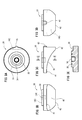
- FIG. 3A is a plan view of the valve body of the first embodiment.
- FIG. 3B is a left side view of the valve body of the first embodiment.
- FIG. 3C is a front view of the valve body of the first embodiment.
- FIG. 3D is a right side view of the valve body of the first embodiment.
- 3E is a cross-sectional view taken along line EE of FIG. 3C. It is a block diagram of the pumping system of 1st embodiment.
- FIG. 5A is a longitudinal sectional view showing a closed state of the check valve of the second embodiment.
- FIG. 5A is a longitudinal sectional view showing a closed state of the check valve of the second embodiment.
- FIG. 5B is a longitudinal sectional view showing an open state of the check valve of the second embodiment. It is a perspective view of the valve body of 2nd embodiment.
- FIG. 7A is a longitudinal sectional view showing a closed state of the check valve of the third embodiment.
- FIG. 7B is a longitudinal sectional view showing an open state of the check valve of the third embodiment.
- FIG. 8A is a longitudinal sectional view showing a closed state of the check valve of the fourth embodiment.
- FIG. 8B is a longitudinal sectional view showing an open state of the check valve of the fourth embodiment. It is explanatory drawing of the closed state of the non-return valve of 4th embodiment.
- FIG. 10A is an explanatory diagram of a resin sheet.
- FIG. 10A is an explanatory diagram of a resin sheet.
- FIG. 10B is an explanatory diagram of a modified example of the resin sheet. It is a block diagram of the pumping system of 2nd embodiment.
- FIG. 12A is a schematic cross-sectional view showing a first example of the lower end portion of the liquid absorption pipe.
- FIG. 12B is a schematic cross-sectional view showing a second example of the lower end portion of the liquid absorption pipe. It is explanatory drawing of the closed state of the non-return valve of 5th embodiment. It is explanatory drawing of the open state of the non-return valve of 5th embodiment.
- the inflow side to the check valve is called the primary side, and the outflow side is called the secondary side.
- the opening direction of the valve body is shown upward, and the closing direction of the valve body and the fluid inflow side may be referred to as the lower side, but this does not necessarily indicate the direction of gravity or the direction of installation of the check valve with respect to the piping. It is not shown.
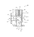
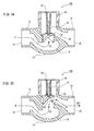
- FIG. 1 is a longitudinal sectional view of a check valve 100 according to the first embodiment of the present invention.
- FIG. 1 shows a closed state of the valve body 30.
- FIG. 2 is a longitudinal sectional view of the check valve 100 showing the opened state of the valve body 30.
- 3A to 3E are explanatory views of the valve body 30.
- the check valve 100 includes a valve seat 20 and a valve body 30 that reciprocally swings linearly in a direction approaching or separating from the valve seat 20 to close the valve seat 20 so as to be freely opened and closed.
- the check valve 100 is a lift type check valve in which an inflow direction D1 of the fluid F flowing into the valve seat 20 intersects a passing direction D2 in which the fluid F passes through the valve body 30.
- a turning surface 40 that turns the fluid F from the inflow direction D1 to the passage direction D2 is provided on the inflow side (primary side) of the valve body 30.
- the upstream side of the fluid F rectified by the check valve 100 is referred to as the primary side of the check valve 100, and the downstream side is referred to as the secondary side.
- the fluid F is a liquid such as water or a gas such as air.
- the check valve 100 of the present embodiment is provided in a flow path through which liquid or gas flows, and the differential pressure between the primary side and the secondary side of the valve body 30 exceeds a predetermined minimum operating pressure (cracking pressure). Sometimes fluid F is circulated. When the differential pressure between the primary side and the secondary side of the valve body 30 is negative or less than the minimum operating pressure, the valve body 30 is closed and the flow of the fluid F is blocked.
- the check valve 100 further includes a valve box 10 that houses the valve seat 20 and the valve body 30.
- the valve box 10 includes a valve cylinder 18, an inflow cylinder 12 that constitutes a flow path on the primary side of the valve body 30, and an outflow cylinder 16 that constitutes a flow path on the secondary side of the valve body 30.
- the end face 13 inside the valve box in the inflow cylinder 12 has an inclined shape corresponding to the turning surface 40. Thereby, the end face 13 of the inflow tube 12 constitutes the valve seat 20.
- the inflow cylinder 12 and the outflow cylinder 16 are straight cylinders, and the axial direction is linear.
- the axial direction of the inflow tube 12 corresponds to the inflow direction D1
- the axial direction of the outflow tube 16 corresponds to the passage direction D2.
- a flange 22 having a diameter larger than that of the inflow cylinder 12 is provided on the end surface 15 on the primary side of the inflow cylinder 12.
- the collar portion 22 may be detachably attached to the inflow tube 12.
- the flange 22 may be fixed to the inflow cylinder 12 so as not to be separated.
- the collar part 22 and the inflow cylinder 12 may be integrally molded by one material.
- a plurality of bolt holes are formed in the collar portion 22 of the present embodiment.
- An opening 23 having the same diameter as the inner diameter of the inflow tube 12 is formed in the center of the flange portion 22.
- the opening 23 is an inlet of the check valve 100.
- the end surface 17 on the secondary side of the outflow tube 16 is provided with a flange 24 having a diameter larger than that of the outflow tube 16.
- the flange portion 24 may be detachably attached to the outflow tube 16, may be fixed to the outflow tube 16 so as not to be separable, or is integrally formed with the outflow tube 16. May be.
- a plurality of bolt holes are formed in the flange portion 24.
- An opening 25 having the same diameter as the inner diameter of the outflow tube 16 is formed at the center of the flange 24.
- the opening 25 is an outlet of the check valve 100.
- the flanges 22 and 24 serve as joints for fixing the check valve 100 to a pipe (for example, a liquid absorption pipe 210: see FIG. 4).
- the inflow direction D1 and the passage direction D2 are orthogonal to each other. That is, the check valve 100 is an angle valve in which the axial directions of the inflow cylinder 12 and the outflow cylinder 16 intersect each other.
- the term “direction” such as the inflow direction D1 and the passage direction D2 may be used as a vector having a direction (directed).
- the check valve 100 includes an elastic body 50 and a cap portion 60.
- the elastic body 50 is a member that biases the valve body 30 toward the valve seat 20.
- a spiral spring can be exemplified as the elastic body 50.
- the cap part 60 is a member that is detachable from the valve box 10 and supports the valve body 30 and the elastic body 50.
- the valve body 30 and the elastic body 50 can be detached from the valve box 10 by detaching the cap part 60 from the valve box 10.
- the cap part 60 is screwed with respect to the valve cylinder 18 along the extending direction of the inflow cylinder 12 (the swinging direction of the valve body 30).
- the valve cylinder 18 has a cylindrical shape and is provided with a side hole 19 on the peripheral surface.
- the outflow cylinder 16 is detachably attached to the side hole 19 or is fixed so as not to be separated.
- the inflow cylinder 12 is fixedly fitted to one end (the lower end in FIGS. 1 and 2) of the valve cylinder 18 in a detachable or non-separable manner.
- the upper end surface 13 of the inflow cylinder 12 is inserted into the valve cylinder 18.
- the cap portion 60 includes a top plate portion 62, a straight tube portion 64 erected substantially at the center of the top plate portion 62, and a peripheral surface portion 66 that stands up from the periphery of the top plate portion 62.
- the cap portion 60 is detachably fitted to the other end (the upper end in FIGS. 1 and 2) of the valve cylinder 18.
- the elastic body 50 is attached to the outer periphery of the straight tube portion 64.
- a guide shaft 32 is slidably inserted into the straight cylindrical portion 64.
- the guide shaft 32 is detachably installed on the secondary side of the valve body 30 (upper side in FIGS. 1 and 2). Specifically, a male screw portion is formed at the lower end of the guide shaft 32 and is screwed into a retaining hole 34 of the valve body 30 described later.
- the valve body 30 reciprocally swings linearly in the contact / separation direction with respect to the valve seat 20.
- the inflow cylinder 12 and the outflow cylinder 16 communicate with each other when the valve body 30 is separated from the valve seat 20. As a result, the fluid F can pass through the check valve 100.
- a key groove 52 extending along the sliding direction of the guide shaft 32 is formed on the inner peripheral surface of the valve cylinder 18.
- the key groove portion 52 engages with a protrusion 43 that is a part of the valve body 30 to guide the reciprocating swing of the valve body 30.
- the check valve 100 of the present embodiment includes a guide portion that guides the valve body 30 to slide unrotatably with respect to the cap portion 60.
- the protrusion 43 and the key groove 52 correspond to the guide portion.
- the elastic body 50 slightly presses the valve body 30 against the valve seat 20 in the closed state in which the valve body 30 and the valve seat 20 are in contact with each other. That is, the elastic body 50 is slightly contracted from the natural length when the valve body 30 is closed. When the valve body 30 is separated from the valve seat 20, the elastic body 50 further contracts, and the urging force that presses the valve body 30 toward the valve seat 20 increases. When the gravitational acceleration acting on the check valve 100 is ignored, the valve body 30 rises from the valve seat 20 to a position where the urging force of the elastic body 50 against the valve body 30 is balanced with the total pressure (water flow pressure) of the fluid F (FIG. 2).
- the turning surface 40 smoothly turns the inflow direction D1 of the fluid F passing through the valve seat 20 to the passing direction D2 of the valve body 30.
- the passage direction D2 of the valve body 30 is a direction in which the fluid F flowing into the valve cylinder 18 passes through the side hole 19, that is, a substantially normal direction of the side hole 19.
- the turning surface 40 is a plane or a curved surface that is inclined in the direction of the vector sum of the directed inflow direction D1 and the passing direction D2.
- the shape of the turning surface 40 is not particularly limited, and may be a flat surface, a two-dimensional curved surface obtained by bending the flat surface around one axis, or a three-dimensional curved surface obtained by bending the flat surface around a plurality of axes.
- the turning surface 40 of the present embodiment is a curved surface that is convex toward the direction in which the valve body 30 is separated from the valve seat 20. More specifically, the turning surface 40 of the present embodiment is a partial cylindrical surface (two-dimensional curved surface) having a cylindrical axis in a direction that intersects both the inflow direction D1 and the passage direction D2 (left-right direction in FIG. 3B). It is.
- the cylinder includes a long cylinder and an elliptic cylinder.
- the radius of curvature of the partial cylindrical surface of the turning surface 40 is larger than the flow path radius of the fluid F flowing into the valve seat 20. Thereby, the fluid F is not turned too rapidly and the force by which the fluid F pushes up the valve body 30 does not become too small. For this reason, the cracking pressure of the check valve 100 does not become excessive.
- the flow path radius of the fluid F flowing into the valve seat 20 is the inner diameter (radius) of the inflow cylinder 12 and is the opening radius of the valve seat 20 projected in the inflow direction D1.
- the radius of curvature of the partial cylindrical surface of the turning surface 40 of this embodiment is larger than the diameter of the flow path of the fluid F flowing into the valve seat 20.
- the component in the direction along the guide shaft 32 (the swinging direction of the valve body 30) of the force that the inflowing fluid F presses the turning surface 40 is the component in the direction orthogonal to the guide shaft 32 (lateral force).
- the shape and size of the turning surface 40 of the present embodiment projected in the inflow direction D1 are equal to the opening shape and size of a cross section obtained by cutting the inflow tube 12 perpendicularly to the inflow direction D1.
- the curvature radius of the turning surface 40 of this embodiment is uniform as a whole, the curvature radius of the turning surface 40 may be locally changed instead of this embodiment.
- the entire turning surface 40 faces the inside of the opening of the inflow tube 12.
- the valve body 30 has a substantially disk shape.
- the turning surface 40 and the valve body 30 are integrally formed as one material.
- the side of the valve body 30 on which the turning surface 40 is formed is referred to as a lower surface, and the opposite side is referred to as an upper surface.
- a thick reinforcing portion 33 is formed on the upper surface of the valve body 30.
- a retaining hole 34 is provided in the center of the reinforcing portion 33.
- a spiral groove (not shown) is formed on the peripheral surface of the retaining hole 34, and the male thread portion at the lower end of the guide shaft 32 is screwed together.
- An annular groove 35 is formed around the retaining hole 34 in the reinforcing portion 33. The lower end of the elastic body 50 is fitted into the annular groove 35.
- the horizontal direction in FIG. 3B is referred to as the width direction.
- the left side of FIG. 3C is referred to as the front side
- the right side is referred to as the rear side.
- a front edge flat portion 41 is smoothly and continuously formed with respect to the turning surface 40 in front of the direction of inclination of the turning surface 40 (left and right direction in FIG. 3C).
- a rear edge flat portion 42 is formed to bend with respect to the turning surface 40 behind the turning surface 40.
- the normal direction of the front edge flat portion 41 and the rear edge flat portion 42 is in agreement with the depth direction of the retaining hole 34, that is, the swinging direction of the valve body 30.
- the maximum dimension in the width direction of the leading edge flat part 41 is smaller than the dimension of the turning surface 40 and larger than the dimension of the trailing edge flat part 42.
- the turning surface 40 has a tail shape in which the dimension in the width direction gradually decreases toward the trailing edge flat portion 42.
- a protrusion 43 is formed behind the trailing edge flat portion 42 on the peripheral surface of the valve body 30.
- the protrusion 43 of the present embodiment has a semi-cylindrical shape and extends in the swinging direction of the valve body 30.
- the protrusion 43 is slidably fitted to the key groove 52 of the valve cylinder 18.
- the front edge flat portion 41 and the rear edge flat portion 42 are in liquid-tight contact with the flat portion 13 a on the end surface 13 of the inflow tube 12 (see FIGS. 1 and 2).
- a water-stopping packing such as an O-ring may optionally be interposed.
- the specific interposition part of the packing is not particularly limited, but an annular packing may be attached to the end surface 13 of the inflow cylinder 12 in a circular shape, or the front edge flat portion 41, the turning surface 40 and the rear edge flat portion 42 may be attached. An annular packing may be attached in a circular manner.
- the valve body 30 may be brought into direct contact with the valve seat 20 in a closed state without using packing. Since the normal direction of the leading edge flat portion 41 and the trailing edge flat portion 42 coincides with the inflow direction D1, these portions are in the inflow direction D1 (that is, with respect to the flat portion of the end surface 13 of the inflow cylinder 12). It touches straight along the direction of water fall. For this reason, the valve body 30 of this embodiment is excellent in the water stoppage in a closed state, without using packing, although it has the curved turning surface 40.
- the fluid F that has flowed in from the primary end surface 15 of the inflow cylinder 12 with the valve body 30 closed gives a vertical drag to the turning surface 40.
- the component in the extending direction of the guide shaft 32 in the vertical drag compresses the elastic body 50 and pushes up the valve body 30 from the valve seat 20.
- the fluid F flows along the turning surface 40 and stays in the vicinity of the front edge flat portion 41, that is, in the vicinity of the side hole 19. Therefore, when the valve body 30 is opened, the fluid F immediately flows out from the side hole 19.
- the fluid F flowing in the inflow direction D1 collides with the turning surface 40 and turns in the passing direction D2 along the turning surface 40 while maintaining the opened state of the valve body 30. .
- the check valve 100 When the lift of the valve body 30 with respect to the valve seat 20 is restricted and reaches the maximum lift position, the check valve 100 is in the maximum open state.
- the upper surface of the reinforcing portion 33 of the rising valve body 30 abuts on the lower end of the straight cylinder portion 64, so that the valve body 30 is prevented from rising.
- the lower end portion of the guide shaft 32 and the valve body 30 are located inside the valve cylinder 18 in the maximum open state of the check valve 100.
- the valve cylinder 18 has a cylindrical shape, and the inner diameter thereof matches the outer diameter of the valve body 30.
- the valve body 30 reciprocally swings in a liquid-tight manner inside the valve cylinder 18.
- the valve body 30 is accommodated in the valve cylinder 18 over the entire stroke from the closed state in which the valve body 30 is in contact with the valve seat 20 to the maximum open state. For this reason, the fluid F flowing in from the inflow direction D1 flows out of the check valve 100 through the side hole 19 and the outflow tube 16 without flowing into the back of the valve body 30, that is, inside the cap portion 60. Since the fluid F does not flow into the cap portion 60, the rise of the valve body 30 is not hindered.
- the air inside the cap part 60 is compressed as the valve body 30 rises.
- the top plate portion 62 or the peripheral surface portion 66 of the cap portion 60 may be provided with a vent hole for releasing the compressed air.
- the valve body 30 can be quickly transitioned from the open state to the closed state using the elastic restoring force of the compressed air. .
- the valve body 30 closes quickly at the time of the stop of the fluid F, the backflow of the fluid F on the secondary side of the check valve 100 can be well prevented.
- the check valve 100 As a so-called foot valve on the primary side of the pump, it is possible to prevent water from falling by utilizing such a backflow prevention function.
- the fluid F flowing in from the inflow direction D1 may be configured to flow behind the valve body 30, that is, into the cap portion 60.
- a slight gap is provided between the periphery of the valve body 30 and the valve cylinder 18, and in the opened state shown in FIG. 2, the liquid L flows into the cap portion 60 and then flows into the outflow cylinder 16.
- You may comprise. Thereby, the inside of the cap part 60 can be kept clean by the flowing liquid L, and even when a foreign matter is engaged with the elastic body 50, the foreign matter can be immediately washed away.
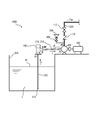
- FIG. 4 is a configuration diagram of a pumping system 1000 using the check valve 100 as a foot valve.
- the pumping system 1000 is used for various purposes such as water supply and sewage supply, water supply for fire extinguishing and ballast, and coolant supply.
- the liquid L to be pumped can be selected according to the use other than water.
- the pumping system 1000 of this embodiment includes a liquid storage tank 200 that stores the liquid L, a pump 300 that is installed on the ground and pumps the liquid, and a liquid suction pipe 210 that connects the liquid storage tank 200 and the pump 300. And a discharge pipe 220 through which the liquid L discharged from the pump 300 is circulated.
- the check valve 100 is provided on the ground portion of the liquid suction pipe 210.
- a driving unit 302 such as a motor is connected to the pump 300.
- the pump 300 is a land pump and may be self-priming or non-self-priming. In this embodiment, a non-self-priming centrifugal pump is illustrated.
- the expiratory water tank 304 is installed higher than the pump 300. Expired water is supplied to the pump 300 by opening the on-off valve 306.
- the liquid suction pipe 210 includes a suction part 212 that is installed upright and has a lower end 213 immersed in the liquid storage tank 200, and a transfer unit 216 that is installed on the ground and connected to the pump 300.
- the check valve 100 is provided between the suction part 212 and the transfer part 216.
- the lower end 213 of the liquid suction pipe 210 is below the liquid level FL of the liquid L.
- the transfer unit 216 is installed between the secondary side of the check valve 100 and the suction side SS of the pump 300.
- the transfer part 216 is inclined upward toward the pump 300 with a gradient ⁇ .
- the check valve 100 opens the flow path by the discharge pressure of the pump 300 and unilaterally passes the liquid L in a direction to send the liquid L from the suction part 212 (primary side UP) to the transfer unit 216 (secondary side DW).
- the discharge pipe 220 connected to the discharge side DS of the pump 300 is provided with a second check valve 110 that unidirectionally distributes the liquid L discharged from the pump 300 in the discharge direction (upward in FIG. 4). .
- an on-off valve 112 is installed on the further secondary side of the second check valve 110.
- the flow path of the transfer unit 216 is closed and the transfer unit 216 becomes high pressure.
- the differential pressure between the primary side UP and the secondary side DW of the check valve 100 becomes equal to or lower than the minimum operating pressure (cracking pressure), and the valve body 30 closes quickly.
- the liquid L inside the transfer unit 216 stays inside the transfer unit 216 without falling from the check valve 100 which is a foot valve.
- the liquid L inside the suction part 212 also stays in the inside without falling down.
- the pump 300 is restarted, it is not necessary to supply exhalation water from the exhalation tank 304 to the suction part 212 and the transfer unit 216, or the supply amount can be minimized.
- the check valve 100 since the check valve 100 is installed on the ground part, its mounting and maintenance workability is excellent.
- the check valve 100 of this embodiment is further excellent in maintenance workability because the cap portion 60 is detachably attached to the upper end of the valve cylinder 18.
- the pump 300 When foreign matter is caught between the valve body 30 and the valve cylinder 18 or when the sliding property between the guide shaft 32 and the straight cylinder portion 64 or the elasticity of the elastic body 50 is lowered, the pump 300 is stopped. Then, the cap part 60 is removed from the valve cylinder 18. Thereby, the elastic body 50, the guide shaft 32, and the valve body 30 can be easily removed from the valve cylinder 18.
- the valve body 30 that is a movable part of the check valve 100 is valved without removing the liquid suction pipe 210 (the suction part 212, the transfer part 216) and the valve box 10. It can be easily removed from the box 10 for maintenance work.
- the check valve 100 may be installed in a gas flow path such as an air duct (ventilating pipe) and used as a check damper for preventing a reverse flow that allows gas (air) to pass through unilaterally.
- FIG. 5A and 5B are longitudinal sectional views of the check valve 100 of the second embodiment.
- FIG. 5A shows a closed state of the valve body 30, and
- FIG. 5B shows an open state of the valve body 30.
- the check valve 100 of this embodiment is common to the first embodiment in the following points. That is, it is an angle valve in which the axial directions of the inflow cylinder 12 and the outflow cylinder 16 intersect each other.
- An elastic body 50 and a guide shaft 32 are mounted behind (secondary side) the valve body 30 that linearly reciprocates with respect to the valve seat 20, and the valve body 30 is elastically biased by the valve seat 20.
- the cap part 60 is screwed with respect to the valve cylinder 18 in the swinging direction of the valve body 30 and is detachable from the valve cylinder 18.
- the turning surface 40 of the present embodiment includes a first partial cylindrical surface 46 having a cylindrical axis in a direction intersecting both the inflow direction D1 and the passage direction D2, and a second partial cylinder having the inflow direction D1 as a cylindrical axis. It differs from the first embodiment in that it is a composite surface with the surface 48.
- the valve box 10 includes a valve cylinder 18, an inflow cylinder 12, an outflow cylinder 16, and flanges 22 and 24.
- the valve cylinder 18, the inflow cylinder 12, and the outflow cylinder 16 of this embodiment are integrated with each other.
- the specific manufacturing method of the valve cylinder 18, the inflow cylinder 12, and the outflow cylinder 16 is not specifically limited, these may be integrally formed by one material by casting, or after forming these as separate parts, it is a T type joint. You may connect mutually using connection members, such as.
- the flanges 22 and 24 are integrated with the valve cylinder 18.
- An inner flange 26 is formed at the boundary between the inflow cylinder 12 and the valve cylinder 18.
- An end face of the inner flange 26 facing the valve cylinder 18 constitutes the valve seat 20.
- FIG. 6 is a perspective view of the valve body 30 of the present embodiment.
- the valve body 30 includes a disc-shaped sliding portion 36 and a three-dimensional curved turning surface 40.
- a retaining hole 34, an annular groove 35, and a protrusion 43 are formed in the sliding portion 36.
- the retaining hole 34, the annular groove 35, and the protrusion 43 are the same as those in the first embodiment, and redundant description is omitted.
- the first partial cylindrical surface 46 has a reverse polka dot shape with a sharp bottom end.
- the bending direction of the first partial cylindrical surface 46 is the vector sum direction of the inflow direction D1 and the passage direction D2.
- the second partial cylindrical surface 48 slides with respect to the inner flange 26 and guides the reciprocating swing of the valve body 30.
- the second partial cylindrical surface 48 is a cylindrical surface having a cylindrical axis in the same direction as the peripheral surfaces of the inflow cylinder 12 and the valve cylinder 18.
- the second partial cylindrical surface 48 is a skirt portion that suppresses the fluid F from colliding with the inside of the valve cylinder 18 to generate vortex or turbulence.
- a check function can be obtained at the boundary between intersecting pipes (for example, the suction part 212 and the transfer part 216: FIG. 4).
- the check valve 100 of this embodiment can also be installed on the ground portion of the pumping system 1000 (see FIG. 4) and used as a foot valve.
- the angle valve in which the axial directions of the inflow cylinder 12 and the outflow cylinder 16 are orthogonal to each other is illustrated, but the present invention is not limited to this. It is good also as what is called a straight type non-return valve 100 with which the axial direction of the inflow cylinder 12 and the outflow cylinder 16 is parallel.
- FIG. 7A and 7B are longitudinal sectional views of the check valve 100 of the third embodiment.
- FIG. 7A shows a closed state of the valve body 30, and
- FIG. 7B shows an open state of the valve body 30.
- the check valve 100 of the present embodiment is a straight valve in which the axial directions of the inflow cylinder 12 and the outflow cylinder 16 are parallel, more specifically coincident.
- the check valve 100 of the present embodiment is different from the first and second embodiments in that the axial direction of the inflow tube 12 intersects, specifically, is orthogonal to the extending direction of the guide shaft 32. is doing.
- a primary liquid storage unit 70 is provided inside the valve box 10.
- the primary liquid reservoir 70 is located on the primary side of the valve seat 20.
- the turning surface 40 faces the primary liquid storage unit 70.
- the fluid F that has flowed in from the opening 23 of the inflow cylinder 12 and reached the primary liquid reservoir 70 passes through the valve seat 20 with the opening direction of the valve seat 20 (the vertical direction in FIGS. 7A and 7B) as the inflow direction D1.
- the fluid F that has passed through the valve seat 20 passes through the valve body 30 with the direction along the turning surface 40 as the passing direction D2. Thereafter, the fluid F flows out from the opening 25 along the axial center direction (discharge direction D3) of the outflow tube 16.
- the inflow direction D1 and the passage direction D2 intersect before and after the passage of the valve seat 20.
- the check valve 100 by providing the turning surface 40 on the primary side of the valve body 30, the fluid F can be smoothly turned from the inflow direction D1 to the passage direction D2. Thereby, the loss head in the check valve 100 can be reduced.
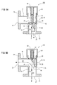
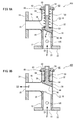
- FIG. 8A is a longitudinal sectional view showing a closed state of the check valve 400 of the fourth embodiment.
- FIG. 8B is a longitudinal sectional view showing an open state of the check valve 400 of the present embodiment.
- FIG. 9 is an explanatory diagram of the closed state of the check valve 400 of the present embodiment.
- the check valve 400 of the present embodiment is the first in that the turning surface 40 is a flat inclined surface, and the intersection angle between the normal direction N of the turning surface 40 and the inflow direction D1 of the fluid F is less than 45 degrees. Different from one embodiment.
- the intersection angle between the normal direction N of the turning surface 40 and the inflow direction D1 of the fluid F will be described.
- the crossing angle when the turning surface 40 is completely facing the inflow direction D1 of the fluid F with respect to the check valve 400 is set to zero degree. That is, the complementary angle of the angle formed by the normal vector (N) of the turning surface 40 and the inflow vector (D1) of the fluid F is the intersection angle of the normal direction N of the turning surface 40 and the inflow direction D1 of the fluid F. It is called.
- this intersection angle may be referred to as an inclination angle of the turning surface 40.
- the inclination angle of the turning surface 40 is preferably less than 45 degrees as described above.
- the fluid F pushes up the turning surface 40 and causes the elastic body 50 to contract favorably, causing the check valve 400 to transition from the closed state of FIG. 8A to the open state of FIG. 8B.
- the inclination angle of the turning surface 40 is preferably 15 degrees or more and 22.5 degrees or less.
- the inclination angle of the turning surface 40 is preferably 1/6 or more and 1/4 or less with respect to the angle at which the inflow direction D1 and the passage direction D2 intersect.
- the thickness of the valve body 30 is non-uniform, and the thickness of the valve body 30 changes monotonically so that the side close to the opening 25 (left side in FIG. 8A) is the thinnest.
- the lower surface of the valve body 30 is inclined with respect to the inflow direction D1 of the fluid F.
- a resin sheet 44 is attached to the lower surface of the valve body 30.
- the resin sheet 44 is a watertight and sheet-like packing member sandwiched between the valve seat 20 and the valve body 30.
- the turning surface 40 of this embodiment is formed by a resin sheet 44.
- As the resin sheet 44 (packing member) a closed cell foamed resin material can be used.
- the resin sheet 44 is flat and has a uniform thickness.
- the lower surface of the resin sheet 44 forms a turning surface 40.
- the resin sheet 44 is a closed cell, the primary side and the secondary side of the check valve 400 do not communicate with each other through the inside of the resin sheet 44, and the water tightness is excellent. That is, when the resin sheet 44 is an open cell, the turning surface 40 and the side peripheral surface of the resin sheet 44 communicate with each other, and water leakage may occur even when the valve body 30 is closed.
- the valve body 30 is excellent in water stoppage in the closed state. That is, a high water stoppage of the check valve 400 can be realized by a synergistic effect of the sealing property of the valve seat 20 due to the resin sheet 44 being flexible and the water tightness of the resin sheet 44 itself.
- the resin sheet 44 is a closed cell, even when the resin sheet 44 is wet with the fluid F, the fluid F is not impregnated to the inside of the resin sheet 44 and the flexible deformability of the resin sheet 44 is impaired. There is nothing. Further, the joint between the resin sheet 44 and the valve body 30 is not eroded by the fluid F impregnated in the resin sheet 44.
- the turning surface 40 of this embodiment is a flat surface.
- the pressing force P1 that the valve body 30 urges the valve seat 20 in the axial direction by the elastic restoring force of the elastic body 50 compressed from the natural length is It is uniform over the circumference of the valve seat 20.
- the force component P2 in the thickness direction of the resin sheet 44 in the pressing force P1 is also uniform over the circumference of the valve seat 20. Since the thickness of the resin sheet 44 is also uniform, the compressive strain in the thickness direction of the resin sheet 44 is uniform. For this reason, the adhesiveness between the resin sheet 44 and the valve seat 20 in the closed state becomes uniform over the circumference of the valve seat 20, and the water stoppage of the check valve 400 of the present embodiment is increased.
- compression set (30 minutes) means that the test piece is compressed to 25% from the initial thickness in accordance with ISO 1856 and left at 23 ° C. ⁇ 2 ° C. for 22 hours. It is the thickness of the test piece after a minute.
- the compression set (24 hours) is the thickness of the test piece after 24 hours from the end of the compression in the same manner.
- a large compression set (30 minutes) means that the resin sheet 44 has a high deformation retention property
- a small compression set (24 hours) means that the resin sheet 44 has a high shape restoring property. To do.
- the water stoppage parameter represented by the above formula (1) is 10 times or more, preferably 15 times or more, because the high water stoppage of the check valve 400 is maintained for a long period of time. This is because if the compression set (30 minutes) is large, the valve seat 20 bites into the resin sheet 44 in a closed state of the check valve 400 and is in close contact with water. Since the compression set (24 hours) is small, the resin sheet 44 is not permanently deformed with the biting shape. For this reason, even if the valve body 30 opens and closes and the relative position between the valve seat 20 and the resin sheet 44 changes minutely, water leakage due to distortion of the resin sheet 44 is preferably prevented.
- foamed resin material for forming the resin sheet 44 polyvinyl chloride foam, olefin foam, urethane foam, or fluororubber foam can be used.
- a non-foamed resin material can be used for the resin sheet 44.
- a soft resin material such as ethylene vinyl acetate copolymer (EVA) or fluororubber can be used.
- valve body 30 and the cap part 60 are rotatable relative to each other, and the elastic body 50 is pressed non-fixed against at least one of the valve body 30 or the cap part 60. This is different from the first embodiment.
- the elastic body 50 is pressed against the valve body 30 or the cap portion 60 in a non-fixed manner.
- the elastic body 50 may be fixedly joined to the other.
- the valve body 30 and the cap part 60 are separable.
- Resin material that frictionally holds the end of the elastic body 50 is provided on at least one of the valve body 30 and the cap portion 60 on which the elastic body 50 is pressed unfixed. Both ends of the elastic body 50 of this embodiment are not fixed to the cap portion 60 and the valve body 30.
- An annular recess 38 is formed on the upper surface of the valve body 30.
- An annular resin pad 54 is fitted into the recess 38.
- An annular recess 69 is similarly formed on the lower surface of the top plate portion 62 of the cap portion 60.
- An annular resin pad 56 is fitted into the recess 69.
- the resin pad 54 and the resin pad 56 may be the same material or different materials.
- the resin sheet 44, the resin pad 54, and the resin pad 56 may be made of a common material, that is, a foamed resin material having closed cells.
- the elastic body 50 In the closed state of the check valve 400 shown in FIG. 8B, the elastic body 50 is compressed. The lower end of the elastic body 50 is pressed by the resin pad 54, and the upper end is pressed by the resin pad 56. In the check valve 400 of the present embodiment, the elastic body 50 is compressed more than the natural length even in the opened state of the check valve 400 shown in FIG. 8A. The lower end of the elastic body 50 is pressed against the resin pad 54 and held frictionally. Similarly, the upper end of the elastic body 50 is pressed against the resin pad 56 and is frictionally held. For this reason, relative axial rotation around the guide shaft 32 is suppressed between the elastic body 50 and the cap portion 60 and between the elastic body 50 and the valve body 30.
- the lower end surface 51 of the elastic body 50 is polished flat. Specifically, the lower end surface 51 is polished by approximately half the thickness of the winding of the elastic body 50. For this reason, the lower end surface 51 and the resin pad 54 are in surface contact, and the shaft rotation of the elastic body 50 is suppressed by a high frictional force. Similarly, the upper end surface (not shown) of the elastic body 50 is also polished flat and in surface contact with the resin pad 56.
- the elastic body 50 has an elastic restoring force against torsional deformation. For this reason, the relative rotation of the valve body 30 and the cap portion 60 around the guide shaft 32 is suppressed by the resin pads 54 and 56 and the elastic body 50.
- the check valve 400 of the present embodiment does not include a guide portion, that is, the key groove portion 52 and the protrusion portion 43 (see FIG. 1), and relative pivoting between the valve body 30 and the cap portion 60 is prohibited. Not. However, as described above, the relative axial rotation of the valve body 30 and the cap portion 60 is regulated frictionally and elastically. For this reason, the position of the valve body 30 with respect to the valve seat 20 is well reproduced before and after the valve body 30 is opened and closed by the inflow of the fluid F. For this reason, it is not necessary to provide a key groove part in the inner surface of the valve cylinder 18 of this embodiment, and the check valve 400 is excellent in workability.
- a packing 68 is inserted between the valve cylinder 18 of the valve box 10 and the cap portion 60 and is pressed in a watertight manner.
- the valve cylinder 18 and the cap part 60 are fastened by a ferrule joint (not shown). Accordingly, the valve body 30 and the elastic body 50 can be detached from the valve box 10 simply by unlocking the ferrule joint and separating the cap portion 60 from the valve cylinder 18.
- the valve body 30 to which the resin sheet 44 is attached is inserted into the valve cylinder 18, and the elastic body 50 is mounted around the guide shaft 32.
- a cap portion 60 is attached to the opening of the valve cylinder 18 in a state where the inclination directions of the turning surface 40 and the valve seat 20 are aligned, and tightened with a ferrule joint.
- the elastic body 50 is compressed, and both ends thereof are pressed against the resin pads 54 and 56, respectively. Thereby, the rotation of the elastic body 50 with respect to the valve body 30 and the cap portion 60 is frictionally restricted.
- the check valve 400 in which the orientation of the turning surface 40 and the valve seat 20 is stably reproduced by a simple assembly operation is provided.
- FIG. 10A is an explanatory view showing a longitudinal section of the resin sheet 44 and the valve seat 20 of the present embodiment.
- FIG. 10B is an explanatory view showing a modified example of the resin sheet 44.
- the resin sheet 44 of this embodiment shown in FIG. 10A has its front end portion 45a and rear end portion 45b rising in the normal direction of the inclined valve seat 20. That is, since the peripheral surface of the resin sheet 44 of the present embodiment rises in parallel with the thickness direction, the resin sheet 44 has a shape excellent in workability.
- the modified resin sheet 44 is different from the present embodiment in that the front end portion 45a and the rear end portion 45b rise in parallel with the axial direction (vertical direction in the drawing) of the inflow tube 12.
- the resin sheet 44 of this embodiment shown in FIG. 10A has a uniform thickness dimension as viewed in the thickness direction.
- the resin sheet 44 of the modification shown in FIG. 10B has a uniform thickness dimension viewed in the axial direction.
- the pressing force P ⁇ b> 1 that the valve body 30 urges the valve seat 20 by the elastic restoring force of the elastic body 50 acts in the axial direction of the check valve 100.
- the reaction force N1 against the pressing force P1 acts on the resin sheet 44 from the valve seat 20 in the axial direction. Since the thickness of the resin sheet 44 in the modification shown in FIG. 10B is uniform in the axial direction, the amount of distortion of the resin sheet 44 compressed by the reaction force N1 reaches from the front end 45a to the rear end 45b. Uniform. For this reason, compared with the resin sheet 44 shown to FIG. 10A, the water stop of the valve seat 20 is excellent.
- the valve seat 20 is stopped by covering the upper surface of the valve seat 20 corresponding to the upper end surface of the inflow cylinder 12 with the resin sheet 44 attached to the lower surface of the valve body 30.
- the valve body 30 may be shaped and dimensioned so that the valve body 30 can be fitted to the inflow cylinder 12, and the inflow cylinder 12 may be plugged with the valve body 30 to stop water.
- the valve body 30 may be a poppet valve having a conical shape that tapers downward.
- the check valve 400 of the present embodiment is configured to restrict the shaft rotation of the valve body 30 by the frictional force between the elastic body 50 and the resin pads 54 and 56. It may replace with this and may provide the guide part which guides that valve body 30 slides with respect to cap part 60 so that rotation is impossible.
- a guide portion that restricts shaft rotation between the valve body 30 and the valve cylinder 18 may be provided, such as the protrusion 43 and the key groove portion 52 of the first embodiment.
- the guide shaft 32 and the straight tube portion 64 may be provided with non-circular cross-sectional portions that engage with each other to restrict relative shaft rotation. This non-circular cross section corresponds to the guide portion.
- the outer peripheral shape of the guide shaft 32 and the inner peripheral shape of the straight cylindrical portion 64 can be non-circular such as an elliptical shape, a semi-circular shape or a partial circular shape obtained by cutting a circular shape.
- This non-circular cross-sectional portion can be provided over the entire length or a partial length of the guide shaft 32 and the straight tube portion 64.
- the guide portion is formed by making the opening shape in the vicinity of the opening end portion (the lower end portion in FIG. 8A) of the straight cylindrical portion 64 noncircular, and the opening shapes in the intermediate portion and the upper portion excluding the vicinity of the opening end portion are circular. It is good to.
- the cross-sectional shape of the entire length region inserted into the straight tube portion 64 of the guide shaft 32 may be a non-circular shape corresponding to the open end portion of the straight tube portion 64.
- the length of the straight cylindrical portion 64 where the opening shape is to be processed in a non-circular shape is locally kept to improve the processing accuracy and reduce the processing cost, and the guide shaft 32 that guides the reciprocating swing of the valve body. Sliding friction can be reduced.
- the check valve 400 is common to the first embodiment in that it includes the valve box 10 that houses the valve seat 20 and the valve body 30.
- the check valve 400 of the present embodiment is different from that of the first embodiment in that it includes a pressure reducing port 105 formed in the primary side UP of the valve body 30 in the valve box 10.
- a pressure reducing port 105 is formed on the valve box 10 of the present embodiment, specifically on the peripheral surface of the inflow cylinder 12. The use of the decompression port 105 will be described with reference to FIG.
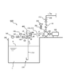
- FIG. 11 is a configuration diagram of a pumping system 1000 according to the second embodiment of the present invention.
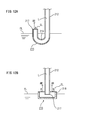
- FIG. 12A is a schematic cross-sectional view showing a first example of the lower end 215 of the liquid suction pipe 210.
- FIG. 12B is a schematic cross-sectional view showing a second example of the lower end 215 of the liquid suction pipe 210.
- the suction part 212 of the liquid suction pipe 210 is connected to the primary side UP of the check valve 400.
- a transfer unit 216 of the liquid suction pipe 210 is connected to the secondary side DW of the check valve 400.
- the suction part 212 communicates with the inside of the liquid storage tank 200, and the transfer unit 216 communicates with the pump 300.
- the check valve 400 circulates the liquid L unilaterally from the primary side UP to the secondary side DW.
- the primary side UP (suction part 212) of the liquid suction pipe 210 is filled with the liquid L and has a negative pressure.
- the lower end 215 of the liquid suction pipe 210 is open vertically upward inside the liquid storage tank 200.
- 12A and 12B show a state in which the liquid level FL has dropped from the state of FIG. 11 and the liquid level FL has become lower than the lower end portion 215 of the liquid suction pipe 210.
- FIG. This occurs when the liquid L stored in the liquid storage tank 200 is pumped by a predetermined amount or more by the pump 300. Due to the water stoppage of the check valve 400, atmospheric pressure acts on the liquid end surface EL of the lower end portion 215 of the liquid suction pipe 210.
- the lower end 215 of the liquid suction pipe 210 of the first example shown in FIG. 12A is bent at a bending angle of about 180 degrees, and the pipe end 217 faces upward.
- the liquid end face EL of the liquid absorption pipe 210 is in the vicinity of the pipe end 217.
- the pumping system 1000 sucks and pumps the liquid L from above the lower end 215 of the liquid suction pipe 210.
- Foreign matter such as sludge having a specific gravity greater than that of the liquid L may be deposited on the bottom of the liquid storage tank 200.
- the lower end part of the liquid absorption pipe is opened downward, it is easy to suck the foreign matter at the bottom part.
- a lower end portion 215 of the liquid suction pipe 210 of the second example shown in FIG. 12B includes a pipe end 217 of the liquid suction pipe 210 that is opened downward, and a water retaining portion 218 that opens upward and accommodates the pipe end 217.
- the liquid end surface EL of the liquid absorption pipe 210 is in the vicinity of the upper surface of the water retention unit 218.
- the pipe end 217 of the liquid absorption pipe 210 is below the liquid end face EL and is immersed in the liquid L.
- the pipe end 217 and the water retention part 218 are integrally connected.
- the area of the upper surface of the water retention part 218 opened, that is, the area of the liquid end surface EL is referred to as the opening area of the water retention part 218.
- the opening area of the water retaining part 218 is not particularly limited, but is preferably larger than the opening area of the pipe end 217 of the liquid suction pipe 210.
- the liquid absorption pipe 210 is filled with the liquid L up to the lower end 215, and the lower end 215 (the pipe end 217 or the water retaining part 218) is opened upward. For this reason, in order for the air AR to enter the liquid absorption pipe 210, it is necessary that the air AR sinks downward from the liquid end surface EL and exceeds the lowermost part of the liquid absorption pipe 210.
- the lowermost part of the liquid suction pipe 210 is a curved portion 219 at the lower end 215, and in the case of the second example in FIG.
- the liquid absorption pipe 210 of this embodiment can maintain the priming state irrespective of the water level of the liquid level FL of the liquid storage tank 200. Therefore, even if the liquid level FL of the liquid storage tank 200 once falls below the lower end portion 215, if the pump 300 is stopped before the suction portion 212 becomes empty, immediately after the water level of the liquid end surface EL is recovered, The pumping of the liquid L can be resumed.
- the liquid end face EL can be easily stabilized without curving the lower end part 215 of the liquid suction pipe 210. .
- the minimum area of the flow path of the lower end 215 from the suction part 212 of the suction pipe 210 to the liquid end surface EL is equal to the opening area of the suction part 212 of the suction pipe 210.
- the opening area of the curved portion 219 and the tube end 217 constituting the lower end portion 215 of the first example, and the flow passage area inside the water retaining portion 218 constituting the lower end portion 215 of the second example are It is equal to or larger than the opening area of the wick 212.
- the water stoppage force by the check valve 400 and the lower end portion 215 opening upward synergistically prevent water falling from the suction portion 212 of the liquid suction pipe 210. For this reason, even when the liquid L is drained from the liquid storage tank 200 and the inside of the liquid storage tank 200 is inspected, the suction portion 212 of the liquid suction pipe 210 is held in a state where water has passed therethrough. Therefore, if the liquid L is stored again in the liquid storage tank 200, the pump 300 can immediately resume the pumping without calling the liquid suction pipe 210.
- the decompression port 105 communicates the inside and outside of the valve box 10 and is an intake hole for decompressing the primary side UP of the valve body 30 in the valve box 10.
- a piping 190 is connected to the decompression port 105.
- the pipe 190 is provided with on-off valves 182 and 183 that shut off the flow path so as to be openable and closable.
- a pressure gauge 185 for measuring the static pressure inside the pipe 190 is connected to the flow path between the on-off valve 182 and the on-off valve 183.
- a vacuum pump 180 is connected to the decompression port 105. Specifically, a vacuum pump 180 is provided at the downstream side of the on-off valve 183, that is, at the end of the pipe 190. The vacuum pump 180 sucks the air inside the pipe 190 without priming. By opening the on-off valves 182 and 183 and operating the vacuum pump 180, the piping 190, the primary side UP of the valve box 10 and the suction part 212 of the liquid suction pipe 210 become negative pressure, and the liquid L is sucked up. Accordingly, the valve body 10 and the suction portion 212 of the liquid suction pipe 210 are initially passed while the valve body 30 of the check valve 400 is closed. In this state, the on-off valve 183 is closed. Thereby, when the pump 300 is stopped, the primary side UP (suction part 212) of the liquid suction pipe 210 is filled with the liquid L and becomes negative pressure.
- the pump 300 of this embodiment is an inverter pump.
- the type of the inverter pump is not particularly limited. Both the PWM method (Pulse Width Modulation) that controls the pump output by changing the current flow rate and the PAM method (Pulse Amplitude Modulation) that controls the pump output by changing the voltage value can be used.
- the inverter pump is a pump whose initial operating pressure is low and gradually increases the operating pressure. Therefore, although it is excellent in energy saving, when the primary UP of the check valve 400 is not priming, this is the initial pump. It takes time to pass water.
- the valve body 30 since the valve body 30 is closed in the initial state, even if the priming water is supplied from the priming water tank 304 to the liquid suction pipe 210, the suction portion 212 cannot be passed through.
- the water suction portion 212 of the liquid suction pipe 210 can be initially passed using the vacuum pump 180, pumping can be started quickly even if an inverter pump is used for the pump 300.
- the pressure gauge 185 connected to the pipe 190 is a vacuum gauge that measures a pressure below atmospheric pressure. While pumping the fluid F with the pump 300, the on-off valve 182 is opened to close the on-off valve 183, and the static pressure of the pipe 190 is measured with the pressure gauge 185.
- the pressure measured by the pressure gauge 185 is the absolute pressure or gauge pressure of the static pressure of the primary side UP of the valve box 10. When this absolute pressure is less than atmospheric pressure, that is, when the gauge pressure is negative, it can be seen that the suction portion 212 is priming higher than the liquid level FL.
- the absolute value of the gauge pressure (negative pressure) and the priming water level (height from the liquid level FL) inside the wick 212 can be converted.
- the gauge pressure measured by the pressure gauge 185 reaches a predetermined pressure (negative pressure) determined based on the height of the valve body 30 from the liquid level FL, the primary side UP of the valve body 30 is completely passed. You can see that it is in a watered state. Conversely, when the gauge pressure measured by the pressure gauge 185 is substantially zero, it can be seen that the primary side UP of the valve body 30 is falling.
- the absolute value of the gauge pressure (negative pressure) measured by the pressure gauge 185 is further increased. For this reason, according to this embodiment, based on the measured value of the pressure gauge 185, it can be discriminate
- the quantitative water level of the priming water inside the wick 212 can be detected by connecting the pressure gauge 185 to the primary side UP in the valve box 10 and measuring the static pressure. Thereby, even when the check valve 400 is installed not in the end of the suction portion 212 but in the middle as in this embodiment, it can be confirmed that the primary side UP is sufficiently initially passed. Furthermore, it can also be determined whether or not the liquid L is being pumped normally. Thereby, idling of the pump 300 can be detected quickly, and the burn-in of the pump 300 can be prevented beforehand.
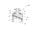
- FIG. 13 is an explanatory view of the closed state of the check valve 400 according to the fifth embodiment of the present invention.
- FIG. 14 is an explanatory diagram of an open state in which the valve body 30 of the check valve 400 according to the fifth embodiment rises in the direction of the broken arrow and is separated from the valve seat 20.
- the elastic body 50 is not shown in FIGS. 13 and 14.
- the check valve 400 of this embodiment is common to the second embodiment in that it includes a resin sheet 44 that is a watertight and sheet-like packing member sandwiched between the valve seat 20 and the valve body 30.
- the point that the packing member is formed of a closed cell foamed resin material is also common to the second embodiment.
- the packing member (resin sheet 44) of the present embodiment includes peripheral portions 44a and 44c sandwiched between the valve seat 20 and the valve body 30, and a plug portion 44b continuously provided inside the peripheral portions 44a and 44c. It has.
- the peripheral portions 44a and 44c are relatively thin, and the plug portion 44b is formed thicker than the peripheral portions 44a and 44c.
- the peripheral portions 44a and 44c and the plug portion 44b are integrally formed as one material.
- the plug portion 44b is a central bulge portion, and the peripheral portions 44a and 44c are flat flange portions.
- the plug portion 44 b constitutes the turning surface 40.
- the inclination angle of the turning surface 40 is less than 45 degrees.
- a region corresponding to the upper side of the inclined resin sheet 44 is referred to as a peripheral portion 44a, and a region corresponding to the lower side of the inclined resin sheet 44 is referred to as a peripheral portion 44c.
- the upper surface of the resin sheet 44 is flat and is attached to the lower surface of the valve body 30.
- a plug portion 44 b is formed to protrude from the lower surface of the resin sheet 44.
- the resin sheet 44 has a circular shape, and annular peripheral portions 44a and 44c having a predetermined width are formed on the outer peripheral side.
- the plug portion 44b is a cylindrical portion that protrudes downward from the peripheral edge portions 44a and 44c.
- the wall thicknesses of the peripheral portions 44a and 44c may be equal to or different from each other.
- the inclination angle ⁇ 1 at which the plug portion 44b rises from the peripheral portion 44a is an obtuse angle
- the inclination angle ⁇ 2 at which the plug portion 44b rises from the peripheral portion 44c is an acute angle.
- the peripheral surface of the plug portion 44 b that is an upright surface from the peripheral edge portions 44 a and 44 c extends along the inner peripheral surface of the inflow tube 12.
- the plug portion 44b stands upright from the peripheral edge portions 44a and 44c, not vertically.
- the plug portion 44b has a slanted cylindrical shape standing from the peripheral edge portions 44a and 44c in the swinging direction of the valve body 30 (vertical direction in FIG. 13).
- the packing member (resin sheet 44) is in close contact with the valve seat 3 three-dimensionally.
- the resin sheet 44 is in three-dimensional contact with the valve seat 20 is not in a state in which the resin sheet 44 is in close contact with only the seat surface of the valve seat 20 but on another surface that is continuous with the seat surface of the valve seat 20. It also means that they are in close contact.
- the resin sheet 44 is in close contact with not only the valve seat 20 but also the inner peripheral surface of the inflow cylinder 12.
- the method for producing the resin sheet 44 including the plug portion 44b is not particularly limited, and the peripheral portions 44a and 44c may be formed by cutting a flat sheet-like resin material having a thickness equivalent to that of the plug portion 44b. .
- the resin material may be press-molded and the peripheral portions 44a and 44c may be pressed and formed thinly.
- the inflow cylinder 12 and the valve body 30 of the check valve 400 may be used as a pressing die, or a pressing die having the same dimensions as these may be used.
- the resin sheet 44 of this embodiment is formed of a foamed resin material having closed cells as described above. For this reason, even when the water flows through the check valve 400 and the resin sheet 44 comes into contact with water, it is possible to prevent water from entering the interior of the resin sheet 44 from the surface layer. Even under the water flow environment of the check valve 400, the bubbles inside the resin sheet 44 are filled with a gas phase, and the resin sheet 44 does not lose good deformability. Therefore, when the valve body 30 reaches a closed state after passing water, the peripheral edge portions 44a and 44c are pressed by the valve seat 20 and the valve body 30, and immediately compressed to make the space between the valve seat 20 and the valve body 30 watertight. Seal.
- the plug portion 44b is slightly pressed against the inner peripheral surface of the inflow tube 12 and is in close contact therewith. Since the resin sheet 44 is a closed cell, the primary water remaining in the inflow cylinder 12 does not pass through the inside of the resin sheet 44 and leak to the secondary side. The plug portion 44b is in close contact with the inflow cylinder 12, and the peripheral portions 44a and 44c are in close contact with the valve seat 20, each having a water stopping power. For this reason, compared with the case where only the valve seat 20 is sealed, the water tightness in the closed state of the check valve 400 is improved.
- the peripheral edge 44a of the resin sheet 44 may be thicker than the peripheral edge 44c, and the inclination angle ⁇ 1 may be smaller than the inclination angle ⁇ 2 (see FIG. 14).
- the guide shaft 32 (see FIG. 13) is eccentric from the center of the valve body 30 and is arranged close to the peripheral portion 44c, the resin sheet 44 adheres well to the valve seat 20 and the check valve.
- the water stoppage of 400 can be improved.
- a fluid that flows into the valve seat including a valve seat and a valve body that linearly reciprocally swings in a direction approaching or separating from the valve seat so as to open and close the valve seat.
- the lift check valve intersects the inflow direction of the fluid and the passage direction in which the fluid passes through the valve body, and the fluid is turned from the inflow direction to the passage direction on the inflow side of the valve body.
- a check valve characterized in that a turning surface is provided.
- the apparatus further includes a valve box that houses the valve seat and the valve body, and the valve box includes an inflow cylinder that forms a flow path on the primary side of the valve body, and a flow path on the secondary side of the valve body.
- An end face inside the valve box of the inflow pipe has an inclined shape corresponding to the turning surface, and the end face constitutes the valve seat.
- a pumping system comprising the check valve according to any one of (1) to (8) above, a liquid storage tank for storing liquid, and a pump that is installed on the ground and pumps the liquid A liquid suction pipe connecting the liquid storage tank and the pump, and a discharge pipe for circulating the liquid discharged from the pump, wherein the check valve is provided on a ground portion of the liquid suction pipe
- the non-return check includes the suction pipe, which is installed upright and the lower end is immersed in the liquid storage tank, and the transfer section that is installed on the ground and connected to the pump.
- the above embodiment further includes the following technical idea.
- Said check valve provided with the watertight and sheet-like packing member clamped by the said valve seat and the said valve body.
- the packing member includes a peripheral portion sandwiched between the valve seat and the valve body, and is formed on the inner side of the peripheral portion so as to be thicker than the peripheral portion to constitute the turning surface.
- the plug portion has a slanted cylindrical shape standing from the peripheral edge in the swinging direction of the valve body, and the packing member is three-dimensional with respect to the valve seat when the valve body is closed.
- Vi The check valve described above, wherein the valve body and the cap portion are rotatable with each other, and the elastic body is pressed against at least one of the valve body or the cap portion in an unfixed manner.
- the above-described check valve in which at least one of the valve body and the cap portion is provided with a resin material that frictionally holds an end portion of the elastic body.
- Said check valve provided with the guide part which guides that the said valve body slides non-rotatably with respect to the said cap part.
- the check valve includes a valve box that houses the valve seat and the valve body, and a pressure reducing opening that is formed on a primary side of the valve body of the valve box.
Landscapes
- Engineering & Computer Science (AREA)
- General Engineering & Computer Science (AREA)
- Mechanical Engineering (AREA)
- Health & Medical Sciences (AREA)
- Life Sciences & Earth Sciences (AREA)
- Hydrology & Water Resources (AREA)
- Public Health (AREA)
- Water Supply & Treatment (AREA)
- Check Valves (AREA)
- Details Of Reciprocating Pumps (AREA)
Description
上記弁座と上記弁体とで挟持される水密性かつシート状のパッキン部材を備えてもよい。
上記パッキン部材は、上記弁座と上記弁体とで挟持される周縁部と、上記周縁部の内側に連設され上記周縁部よりも肉厚に形成されて上記転向面を構成する栓部分と、を備え、上記周縁部と上記栓部分とが一材一体成形されていてもよい。
上記栓部分は、上記弁体の揺動方向に向かって上記周縁部から起立した斜筒状をなしており、上記弁体の閉止時に上記パッキン部材が上記弁座に対して三次元的に密着してもよい。
上記パッキン部材が前記転向面を構成するとともに、独立気泡の発泡樹脂材料により形成されていてもよい。
上記転向面は、上記弁体が上記弁座に対して離間する方向に向かって凸形状をなす湾曲面であってもよい。
上記転向面と上記弁体とが一材一体成形されていてもよい。
上記転向面が、上記流入方向および上記通過方向に対して共に交差する方向を円筒軸とする部分円筒面であってもよい。
上記部分円筒面の曲率半径が、上記弁座に流入する上記流体の流路の直径よりも大きくてもよい。
上記弁座および上記弁体を収容する弁箱を更に備え、上記弁箱は、上記弁体の一次側の流路を構成する流入筒と、上記弁体の二次側の流路を構成する流出筒と、を有し、上記流入筒における弁箱内側の端面は上記転向面に対応する傾斜形状をなし、上記端面が上記弁座を構成していてもよい。
上記流入筒と上記流出筒との軸心方向が互いに交差するアングル弁であってもよい。
上記弁体を上記弁座に向けて付勢する弾性体と、上記弁箱に対して着脱可能であって上記弁体および上記弾性体を支持するキャップ部と、を更に備え、上記キャップ部を上記弁箱から脱離することで上記弁体および上記弾性体が上記弁箱から取り外し可能であってもよい。
上記弁体と上記キャップ部とが互いに回転可能であり、上記弾性体は上記弁体または上記キャップ部の少なくとも一方に対して非固定に押圧されていてもよい。
上記弁体または上記キャップ部の少なくとも上記一方には、上記弾性体の端部を摩擦的に保持する樹脂材料が設けられていてもよい。
上記キャップ部に対して上記弁体が回転不可に摺動することを案内するガイド部を備えてもよい。
上記逆止弁が、上記弁座および上記弁体を収容する弁箱と、上記弁箱の上記弁体の一次側に開口形成された減圧口と、を含み、上記減圧口に真空ポンプが接続されているとともに、上記ポンプがインバーターポンプであってもよい。
図1は本発明の第一実施形態の逆止弁100の縦断面図である。図1は弁体30の閉止状態を示している。図2は弁体30の開放状態を示す逆止弁100の縦断面図である。図3Aから図3Eは弁体30の説明図である。
キャップ部60を弁箱10から脱離することで弁体30および弾性体50は弁箱10から取り外し可能になる。キャップ部60は、流入筒12の延在方向(弁体30の揺動方向)に沿って弁筒18に対して螺進する。
転向面40は、有向の流入方向D1と通過方向D2とのベクトル和の方向に傾斜している平面または曲面である。転向面40の形状は特に限定されず、平面でもよく、平面を一軸まわりに湾曲させた二次元湾曲面でもよく、または平面を複数軸まわりに湾曲させた三次元湾曲面でもよい。
図5A、図5Bは第二実施形態の逆止弁100の縦断面図である。図5Aは弁体30の閉止状態を示し、図5Bは弁体30の開放状態を示す。
図7A、図7Bは第三実施形態の逆止弁100の縦断面図である。図7Aは弁体30の閉止状態を示し、図7Bは弁体30の開放状態を示す。本実施形態の逆止弁100は、流入筒12と流出筒16との軸心方向が平行、より具体的には一致しているストレート弁である。本実施形態の逆止弁100は、流入筒12の軸心方向がガイド軸32の延在方向に対して交差、具体的には直交している点で、第一および第二実施形態と相違している。
図8Aは第四実施形態の逆止弁400の閉止状態を示す縦断面図である。図8Bは本実施形態の逆止弁400の開放状態を示す縦断面図である。図9は本実施形態の逆止弁400の閉止状態の説明図である。
止水性パラメータ=圧縮永久歪み(30分)/圧縮永久歪み(24時間)・・・(1)
図13は本発明の第五実施形態の逆止弁400の閉止状態の説明図である。図14は第五実施形態の逆止弁400の弁体30が破線矢印の方向に上昇して弁座20から離間した状態を示す開放状態の説明図である。図13および図14においては弾性体50を図示省略している。
(1)弁座と、前記弁座に対して接近または離間する方向に直線的に往復揺動して前記弁座を開閉自在に閉止する弁体と、を含み、前記弁座に流入する流体の流入方向と、前記流体が前記弁体を通過する通過方向と、が交差するリフト式逆止弁であって、前記弁体の流入側に、前記流体を前記流入方向から前記通過方向に転向させる転向面が設けられていることを特徴とする逆止弁。
(2)前記転向面は、前記弁体が前記弁座に対して離間する方向に向かって凸形状をなす湾曲面である上記(1)に記載の逆止弁。
(3)前記転向面と前記弁体とが一材一体成形されている上記(2)に記載の逆止弁。
(4)前記転向面が、前記流入方向および前記通過方向に対して共に交差する方向を円筒軸とする部分円筒面である上記(2)または(3)に記載の逆止弁。
(5)前記部分円筒面の曲率半径が、前記弁座に流入する前記流体の流路の直径よりも大きい上記(4)に記載の逆止弁。
(6)前記弁座および前記弁体を収容する弁箱を更に備え、前記弁箱は、前記弁体の一次側の流路を構成する流入筒と、前記弁体の二次側の流路を構成する流出筒と、を有し、前記流入筒における弁箱内側の端面は前記転向面に対応する傾斜形状をなし、前記端面が前記弁座を構成していることを特徴とする上記(1)から(5)のいずれかに記載の逆止弁。
(7)前記流入筒と前記流出筒との軸心方向が互いに交差するアングル弁である上記(6)に記載の逆止弁。
(8)前記弁体を前記弁座に向けて付勢する弾性体と、前記弁箱に対して着脱可能であって前記弁体および前記弾性体を支持するキャップ部と、を更に備え、前記キャップ部を前記弁箱から脱離することで前記弁体および前記弾性体が前記弁箱から取り外し可能である上記(6)または(7)に記載の逆止弁。
(9)上記(1)から(8)のいずれかに記載の逆止弁を備える揚水システムであって、液体を貯留する貯液槽と、地上に設置されて前記液体を揚送するポンプと、前記貯液槽と前記ポンプとを接続する吸液管と、前記ポンプから吐出される前記液体を流通させる吐出管と、を備え、前記逆止弁が前記吸液管の地上部分に設けられていることを特徴とする揚水システム。
(10)前記吸液管が、起立設置されて下端が前記貯液槽に浸漬された吸上部と、地上に横倒設置されて前記ポンプに接続された移送部と、を含み、前記逆止弁が前記吸上部と前記移送部との間に設けられている上記(9)に記載の揚水システム。
(i)前記転向面が平坦な傾斜面であり、前記転向面の法線方向と前記流入方向との交差角度が45度未満である上記の逆止弁。
(ii)前記弁座と前記弁体とで挟持される水密性かつシート状のパッキン部材を備える上記の逆止弁。
(iii)前記パッキン部材は、前記弁座と前記弁体とで挟持される周縁部と、前記周縁部の内側に連設され前記周縁部よりも肉厚に形成されて前記転向面を構成する栓部分と、を備え、前記周縁部と前記栓部分とが一材一体成形されていることを特徴とする上記の逆止弁。
(iv)前記栓部分は、前記弁体の揺動方向に向かって前記周縁部から起立した斜筒状をなしており、前記弁体の閉止時に前記パッキン部材が前記弁座に対して三次元的に密着することを特徴とする上記の逆止弁。
(v)前記パッキン部材が前記転向面を構成するとともに、独立気泡の発泡樹脂材料により形成されている上記の逆止弁。
(vi)前記弁体と前記キャップ部とが互いに回転可能であり、前記弾性体は前記弁体または前記キャップ部の少なくとも一方に対して非固定に押圧されている上記の逆止弁。
(vii)前記弁体または前記キャップ部の少なくとも前記一方には、前記弾性体の端部を摩擦的に保持する樹脂材料が設けられている上記の逆止弁。
(viii)前記キャップ部に対して前記弁体が回転不可に摺動することを案内するガイド部を備える上記の逆止弁。
(ix)前記逆止弁が、前記弁座および前記弁体を収容する弁箱と、前記弁箱の前記弁体の一次側に開口形成された減圧口と、を含み、前記減圧口に真空ポンプが接続されているとともに、前記ポンプがインバーターポンプであることを特徴とする上記の揚水システム。
Claims (19)
- 弁座と、前記弁座に対して接近または離間する方向に直線的に往復揺動して前記弁座を開閉自在に閉止する弁体と、を含み、前記弁座に流入する流体の流入方向と、前記流体が前記弁体を通過する通過方向と、が交差するリフト式逆止弁であって、
前記弁体の流入側に、前記流体を前記流入方向から前記通過方向に転向させる転向面が設けられていることを特徴とする逆止弁。 - 前記転向面が平坦な傾斜面であり、前記転向面の法線方向と前記流入方向との交差角度が45度未満である請求項1に記載の逆止弁。
- 前記弁座と前記弁体とで挟持される水密性かつシート状のパッキン部材を備える請求項1または2に記載の逆止弁。
- 前記パッキン部材は、前記弁座と前記弁体とで挟持される周縁部と、前記周縁部の内側に連設され前記周縁部よりも肉厚に形成されて前記転向面を構成する栓部分と、を備え、前記周縁部と前記栓部分とが一材一体成形されていることを特徴とする請求項3に記載の逆止弁。
- 前記栓部分は、前記弁体の揺動方向に向かって前記周縁部から起立した斜筒状をなしており、前記弁体の閉止時に前記パッキン部材が前記弁座に対して三次元的に密着することを特徴とする請求項4に記載の逆止弁。
- 前記パッキン部材が前記転向面を構成するとともに、独立気泡の発泡樹脂材料により形成されている請求項3から5のいずれか一項に記載の逆止弁。
- 前記転向面は、前記弁体が前記弁座に対して離間する方向に向かって凸形状をなす湾曲面である請求項1に記載の逆止弁。
- 前記転向面と前記弁体とが一材一体成形されている請求項1または7に記載の逆止弁。
- 前記転向面が、前記流入方向および前記通過方向に対して共に交差する方向を円筒軸とする部分円筒面である請求項7または8に記載の逆止弁。
- 前記部分円筒面の曲率半径が、前記弁座に流入する前記流体の流路の直径よりも大きい請求項9に記載の逆止弁。
- 前記弁座および前記弁体を収容する弁箱を更に備え、
前記弁箱は、前記弁体の一次側の流路を構成する流入筒と、前記弁体の二次側の流路を構成する流出筒と、を有し、
前記流入筒における弁箱内側の端面は前記転向面に対応する傾斜形状をなし、前記端面が前記弁座を構成していることを特徴とする請求項1から10のいずれか一項に記載の逆止弁。 - 前記流入筒と前記流出筒との軸心方向が互いに交差するアングル弁である請求項11に記載の逆止弁。
- 前記弁体を前記弁座に向けて付勢する弾性体と、前記弁箱に対して着脱可能であって前記弁体および前記弾性体を支持するキャップ部と、を更に備え、
前記キャップ部を前記弁箱から脱離することで前記弁体および前記弾性体が前記弁箱から取り外し可能である請求項11または12に記載の逆止弁。 - 前記弁体と前記キャップ部とが互いに回転可能であり、前記弾性体は前記弁体または前記キャップ部の少なくとも一方に対して非固定に押圧されている請求項13に記載の逆止弁。
- 前記弁体または前記キャップ部の少なくとも前記一方には、前記弾性体の端部を摩擦的に保持する樹脂材料が設けられている請求項14に記載の逆止弁。
- 前記キャップ部に対して前記弁体が回転不可に摺動することを案内するガイド部を備える請求項13に記載の逆止弁。
- 請求項1から16のいずれか一項に記載の逆止弁を備える揚水システムであって、
液体を貯留する貯液槽と、
地上に設置されて前記液体を揚送するポンプと、
前記貯液槽と前記ポンプとを接続する吸液管と、
前記ポンプから吐出される前記液体を流通させる吐出管と、を備え、
前記逆止弁が前記吸液管の地上部分に設けられていることを特徴とする揚水システム。 - 前記吸液管が、起立設置されて下端が前記貯液槽に浸漬された吸上部と、地上に横倒設置されて前記ポンプに接続された移送部と、を含み、
前記逆止弁が前記吸上部と前記移送部との間に設けられている請求項17に記載の揚水システム。 - 前記逆止弁が、前記弁座および前記弁体を収容する弁箱と、前記弁箱の前記弁体の一次側に開口形成された減圧口と、を含み、
前記減圧口に真空ポンプが接続されているとともに、前記ポンプがインバーターポンプであることを特徴とする請求項17または18に記載の揚水システム。
Priority Applications (6)
| Application Number | Priority Date | Filing Date | Title |
|---|---|---|---|
| JP2013543070A JP5433865B1 (ja) | 2012-05-31 | 2013-05-28 | 逆止弁および揚水システム |
| US14/400,245 US9816622B2 (en) | 2012-05-31 | 2013-05-28 | Check valve and pumping system |
| EP13796343.5A EP2857726B1 (en) | 2012-05-31 | 2013-05-28 | Check valve and hot water system |
| CN201380028546.1A CN104350316B (zh) | 2012-05-31 | 2013-05-28 | 止回阀以及扬水系统 |
| ES13796343T ES2716856T3 (es) | 2012-05-31 | 2013-05-28 | Válvula de retención y sistema de agua caliente |
| IN10951DEN2014 IN2014DN10951A (ja) | 2012-05-31 | 2014-12-22 |
Applications Claiming Priority (4)
| Application Number | Priority Date | Filing Date | Title |
|---|---|---|---|
| JP2012124090 | 2012-05-31 | ||
| JP2012-124090 | 2012-05-31 | ||
| JP2013-012498 | 2013-01-25 | ||
| JP2013012498 | 2013-01-25 |
Publications (1)
| Publication Number | Publication Date |
|---|---|
| WO2013180108A1 true WO2013180108A1 (ja) | 2013-12-05 |
Family
ID=49673300
Family Applications (1)
| Application Number | Title | Priority Date | Filing Date |
|---|---|---|---|
| PCT/JP2013/064732 Ceased WO2013180108A1 (ja) | 2012-05-31 | 2013-05-28 | 逆止弁および揚水システム |
Country Status (7)
| Country | Link |
|---|---|
| US (1) | US9816622B2 (ja) |
| EP (1) | EP2857726B1 (ja) |
| JP (1) | JP5433865B1 (ja) |
| CN (1) | CN104350316B (ja) |
| ES (1) | ES2716856T3 (ja) |
| IN (1) | IN2014DN10951A (ja) |
| WO (1) | WO2013180108A1 (ja) |
Cited By (7)
| Publication number | Priority date | Publication date | Assignee | Title |
|---|---|---|---|---|
| JP2015184210A (ja) * | 2014-03-25 | 2015-10-22 | 大阪瓦斯株式会社 | 開閉弁及びガスメータ |
| JP2016075357A (ja) * | 2014-10-07 | 2016-05-12 | 株式会社イシザキ・コーポレーション | 逆止弁および逆止弁セット |
| WO2019176850A1 (ja) | 2018-03-12 | 2019-09-19 | 株式会社イシザキ | 逆止弁及び逆止弁用往復移動体 |
| JPWO2021152842A1 (ja) * | 2020-01-31 | 2021-08-05 | ||
| JPWO2022191239A1 (ja) * | 2021-03-11 | 2022-09-15 | ||
| JP7458119B1 (ja) | 2023-09-19 | 2024-03-29 | 株式会社横田製作所 | 気液分離装置 |
| WO2026004437A1 (ja) * | 2024-06-26 | 2026-01-02 | 矢崎総業株式会社 | タンクユニット |
Families Citing this family (22)
| Publication number | Priority date | Publication date | Assignee | Title |
|---|---|---|---|---|
| US10125476B1 (en) * | 2012-01-06 | 2018-11-13 | Daniel A. Handley | Apparatus, systems and methods for managing fluids |
| ES2716856T3 (es) * | 2012-05-31 | 2019-06-17 | Ishizaki Corp | Válvula de retención y sistema de agua caliente |
| US9599243B1 (en) * | 2014-08-21 | 2017-03-21 | Taylor Innovations, Llc | Inline relief valve with parabolic piston face |
| JP6496514B2 (ja) * | 2014-10-07 | 2019-04-03 | 株式会社イシザキ | 逆止弁および逆止弁用封止体 |
| LU92958B1 (en) * | 2016-01-25 | 2017-08-07 | Luxembourg Patent Co | High pressure valve with telescopic piston |
| CN106700054B (zh) * | 2016-12-21 | 2019-04-19 | 太仓荣文合成纤维有限公司 | Pbt真空聚合装置用抽真空装置 |
| WO2018209377A1 (en) * | 2017-05-15 | 2018-11-22 | Country Cocky Pty Ltd | Valve for large scale irrigation |
| KR101973119B1 (ko) * | 2017-08-31 | 2019-04-26 | (유)성문 | 체크 밸브 |
| DE102018102251A1 (de) * | 2018-02-01 | 2019-08-01 | Samson Aktiengesellschaft | Ventilgehäuse-Baukastensystem und Hubventil |
| US11148818B2 (en) * | 2018-10-19 | 2021-10-19 | Goodrich Corporation | Aspirator air vent valve |
| US11157026B1 (en) | 2019-01-25 | 2021-10-26 | 3A Holdings, Llc | Apparatus, systems and methods for managing fluids comprising a two-stage poppet valve |
| KR102302329B1 (ko) | 2019-04-02 | 2021-09-15 | 엘지전자 주식회사 | 압축기 |
| CN110206899B (zh) | 2019-06-11 | 2020-11-20 | 佟磊 | 一种控流控压装置 |
| JP7009525B2 (ja) * | 2020-01-31 | 2022-01-25 | 株式会社日本ピスコ | 調圧弁 |
| DE102020207381A1 (de) | 2020-06-15 | 2021-12-16 | Mahle International Gmbh | Ventileinrichtung sowie Brennkraftmaschine mit Ventileinrichtung |
| KR20220125866A (ko) * | 2021-03-04 | 2022-09-15 | 삼성전자주식회사 | 진공 밸브 및 이를 구비한 반도체 제조 장치 |
| IT202100001463U1 (it) * | 2021-03-22 | 2022-09-22 | Ali Group Srl Carpigiani | Macchina per la produzione ed erogazione di prodotti alimentari |
| KR102526009B1 (ko) * | 2021-04-13 | 2023-04-26 | 주식회사 대성코어 | 수류 성능이 향상된 지상식 소화전 |
| DE202021106223U1 (de) * | 2021-11-15 | 2021-11-19 | Feluwa Pumpen Gmbh | Membrankolbenpumpe |
| CN116255488A (zh) * | 2021-12-09 | 2023-06-13 | 成都高真科技有限公司 | 一种用于防止污染的密封组件 |
| KR102618656B1 (ko) * | 2022-04-27 | 2023-12-28 | 주식회사 대성코어 | 옥외 소화전 |
| US20250072719A1 (en) * | 2023-09-05 | 2025-03-06 | Ambu A/S | Endoscope comprising a suction valve |
Citations (6)
| Publication number | Priority date | Publication date | Assignee | Title |
|---|---|---|---|---|
| JPS62183179U (ja) * | 1986-05-14 | 1987-11-20 | ||
| JPH07260020A (ja) * | 1994-03-17 | 1995-10-13 | Harman Co Ltd | 湯水混合バルブ |
| JPH0814425A (ja) | 1994-06-29 | 1996-01-16 | Kosaka Kenkyusho:Kk | アングル型リフト式逆止弁 |
| JP2002213629A (ja) * | 2001-01-19 | 2002-07-31 | Nippo Valve Co Ltd | 減圧式逆流防止装置 |
| JP2002323157A (ja) * | 2001-04-27 | 2002-11-08 | Mitsubishi Electric Corp | 逆流防止弁 |
| JP2003148634A (ja) | 2001-11-13 | 2003-05-21 | Nippon Sanso Corp | 弁および弁体 |
Family Cites Families (40)
| Publication number | Priority date | Publication date | Assignee | Title |
|---|---|---|---|---|
| US199814A (en) * | 1878-01-29 | Improvement in stop-valves | ||
| US704557A (en) * | 1902-01-17 | 1902-07-15 | William R Michener | Check-valve. |
| US862714A (en) * | 1906-10-22 | 1907-08-06 | Boris V Constantinov | Valve. |
| US1679898A (en) | 1924-04-12 | 1928-08-07 | Israel B Gilbert | Check valve |
| US1716722A (en) * | 1925-03-23 | 1929-06-11 | Arthur J Fausek | Valve |
| US2278595A (en) * | 1935-11-05 | 1942-04-07 | Frank E Stelzer | Pump |
| US2521201A (en) * | 1949-02-23 | 1950-09-05 | Bruce E Clark | Radiator pressure cap |
| CH289790A (fr) * | 1950-06-19 | 1953-03-31 | Cableries Et Trefileries Sa De | Vanne de fermeture et de réglage. |
| US2701581A (en) * | 1951-04-13 | 1955-02-08 | Bell & Gossett Co | Flow control valve |
| US2725076A (en) * | 1953-07-03 | 1955-11-29 | Crane Co | Guided closure unit for check valves and the like |
| US3298393A (en) * | 1963-11-15 | 1967-01-17 | Kenneth C Mosier | Check valve having throttling passage |
| US3542332A (en) * | 1968-11-22 | 1970-11-24 | Alain A Chevalier | Air operated poppet seat valve |
| US3613723A (en) * | 1970-02-03 | 1971-10-19 | Max E Witt | Chlorine injection means |
| DE2326609C3 (de) * | 1973-05-24 | 1978-06-22 | Paul 5419 Doettesfeld Kunz | Dampfschälanlage mit einem Druckbehälter |
| US3911950A (en) * | 1974-05-03 | 1975-10-14 | Lunkenheimer | Pre-set pressure relief valve |
| DE7633291U1 (de) | 1976-10-23 | 1977-02-03 | Oscar Gossler Kg, 2057 Reinbek | Rueckschlagventil fuer zapfventile |
| US4270571A (en) * | 1979-07-06 | 1981-06-02 | Pauliukonis Richard S | High pressure letdown valve |
| GB2085128A (en) * | 1980-10-03 | 1982-04-21 | Saunders Philip Keith | Valves |
| JPS57107488A (en) * | 1980-10-03 | 1982-07-03 | Kei Saundaasu Fuiritsupu | Y-shaped valve device |
| IL63718A0 (en) * | 1981-01-28 | 1981-12-31 | Dorot Foundry & Metal Works | Check valve |
| US4576197A (en) * | 1982-09-29 | 1986-03-18 | Midwest Energy Services Company | Pump suction vacuum lift vortex control |
| DE3407190A1 (de) * | 1984-02-28 | 1985-09-12 | Gerhard 5330 Königswinter Esser | Vorrichtung zur abfuellung von fluessigkeiten |
| US4757974A (en) * | 1987-04-13 | 1988-07-19 | Ward Erin C | Check valve |
| US4883086A (en) * | 1988-10-26 | 1989-11-28 | Lejnar Emil A | Aspiration chemical supply apparatus and method |
| US5797421A (en) * | 1994-01-12 | 1998-08-25 | Schlumberger Industries, Inc. | Dry hydrant siphon assembly |
| US5915410A (en) | 1996-02-01 | 1999-06-29 | Zajac; John | Pneumatically operated positive shutoff throttle valve |
| GB2344635B (en) * | 1998-12-09 | 2003-04-30 | Kitz Corp | Ball check valve and pumping apparatus using the check valve |
| US6929238B2 (en) * | 2000-02-18 | 2005-08-16 | Ga Industries Inc. | Electric motor actuated stop and self-closing check valve |
| DE10243291B4 (de) * | 2002-09-18 | 2015-04-30 | Mann + Hummel Gmbh | Ventil, insbesondere für den Ölkreislauf einer Brennkraftmaschine |
| CN2584981Y (zh) | 2002-11-22 | 2003-11-05 | 宁波法兰特阀门有限公司 | 升降式缓闭止回阀 |
| CN2603881Y (zh) | 2003-03-11 | 2004-02-18 | 王斌 | 斜面截止阀 |
| US20050271518A1 (en) * | 2004-06-04 | 2005-12-08 | Smith & Loveless, Inc. | Pumping method and system |
| JP4831422B2 (ja) * | 2006-07-19 | 2011-12-07 | 豊田合成株式会社 | 流量可変バルブ |
| US7921867B2 (en) * | 2006-09-06 | 2011-04-12 | Olmsted Products Co. | Elbow plug external sleeve valve |
| EP2194108A4 (en) | 2007-08-24 | 2015-04-22 | Sekisui Chemical Co Ltd | SEALING ELEMENT |
| SG153002A1 (en) * | 2007-11-16 | 2009-06-29 | Millipore Corp | Fluid transfer device |
| CN101487537A (zh) | 2008-12-05 | 2009-07-22 | 广东联塑科技实业有限公司 | 一种管道截止阀 |
| CN101672368A (zh) | 2009-09-01 | 2010-03-17 | 广东联塑科技实业有限公司 | 一种管道截止阀 |
| CN201546972U (zh) | 2009-09-29 | 2010-08-11 | 英德佳纳金属科技有限公司 | 一种高吸程离心泵装置 |
| ES2716856T3 (es) * | 2012-05-31 | 2019-06-17 | Ishizaki Corp | Válvula de retención y sistema de agua caliente |
-
2013
- 2013-05-28 ES ES13796343T patent/ES2716856T3/es active Active
- 2013-05-28 JP JP2013543070A patent/JP5433865B1/ja active Active
- 2013-05-28 CN CN201380028546.1A patent/CN104350316B/zh active Active
- 2013-05-28 US US14/400,245 patent/US9816622B2/en not_active Expired - Fee Related
- 2013-05-28 WO PCT/JP2013/064732 patent/WO2013180108A1/ja not_active Ceased
- 2013-05-28 EP EP13796343.5A patent/EP2857726B1/en active Active
-
2014
- 2014-12-22 IN IN10951DEN2014 patent/IN2014DN10951A/en unknown
Patent Citations (6)
| Publication number | Priority date | Publication date | Assignee | Title |
|---|---|---|---|---|
| JPS62183179U (ja) * | 1986-05-14 | 1987-11-20 | ||
| JPH07260020A (ja) * | 1994-03-17 | 1995-10-13 | Harman Co Ltd | 湯水混合バルブ |
| JPH0814425A (ja) | 1994-06-29 | 1996-01-16 | Kosaka Kenkyusho:Kk | アングル型リフト式逆止弁 |
| JP2002213629A (ja) * | 2001-01-19 | 2002-07-31 | Nippo Valve Co Ltd | 減圧式逆流防止装置 |
| JP2002323157A (ja) * | 2001-04-27 | 2002-11-08 | Mitsubishi Electric Corp | 逆流防止弁 |
| JP2003148634A (ja) | 2001-11-13 | 2003-05-21 | Nippon Sanso Corp | 弁および弁体 |
Non-Patent Citations (1)
| Title |
|---|
| See also references of EP2857726A4 |
Cited By (17)
| Publication number | Priority date | Publication date | Assignee | Title |
|---|---|---|---|---|
| JP2015184210A (ja) * | 2014-03-25 | 2015-10-22 | 大阪瓦斯株式会社 | 開閉弁及びガスメータ |
| JP2016075357A (ja) * | 2014-10-07 | 2016-05-12 | 株式会社イシザキ・コーポレーション | 逆止弁および逆止弁セット |
| WO2019176850A1 (ja) | 2018-03-12 | 2019-09-19 | 株式会社イシザキ | 逆止弁及び逆止弁用往復移動体 |
| JP6649534B1 (ja) * | 2018-03-12 | 2020-02-19 | 株式会社イシザキ | 逆止弁及び逆止弁用往復移動体 |
| US10907743B2 (en) | 2018-03-12 | 2021-02-02 | Ishizaki Co., Ltd. | Check valve and reciprocating body for check valve |
| JPWO2021152842A1 (ja) * | 2020-01-31 | 2021-08-05 | ||
| JP7068500B2 (ja) | 2020-01-31 | 2022-05-16 | 株式会社イシザキ | 逆止弁 |
| US11828373B2 (en) | 2020-01-31 | 2023-11-28 | Ishizaki Co., Ltd. | Check valve |
| WO2022191239A1 (ja) | 2021-03-11 | 2022-09-15 | 株式会社イシザキ | 逆止弁 |
| TWI812060B (zh) * | 2021-03-11 | 2023-08-11 | 日商石崎股份有限公司 | 止回閥 |
| JPWO2022191239A1 (ja) * | 2021-03-11 | 2022-09-15 | ||
| JP7557610B2 (ja) | 2021-03-11 | 2024-09-27 | 株式会社イシザキ | 逆止弁 |
| US12292124B2 (en) | 2021-03-11 | 2025-05-06 | Ishizaki Co., Ltd. | Check valve |
| JP7458119B1 (ja) | 2023-09-19 | 2024-03-29 | 株式会社横田製作所 | 気液分離装置 |
| WO2025062697A1 (ja) * | 2023-09-19 | 2025-03-27 | 株式会社 横田製作所 | 気液分離装置 |
| JP2025043876A (ja) * | 2023-09-19 | 2025-04-01 | 株式会社横田製作所 | 気液分離装置 |
| WO2026004437A1 (ja) * | 2024-06-26 | 2026-01-02 | 矢崎総業株式会社 | タンクユニット |
Also Published As
| Publication number | Publication date |
|---|---|
| IN2014DN10951A (ja) | 2015-09-18 |
| US9816622B2 (en) | 2017-11-14 |
| EP2857726A1 (en) | 2015-04-08 |
| EP2857726A4 (en) | 2016-01-20 |
| EP2857726B1 (en) | 2018-12-26 |
| JPWO2013180108A1 (ja) | 2016-01-21 |
| CN104350316A (zh) | 2015-02-11 |
| CN104350316B (zh) | 2017-07-07 |
| JP5433865B1 (ja) | 2014-03-05 |
| ES2716856T3 (es) | 2019-06-17 |
| US20150122353A1 (en) | 2015-05-07 |
Similar Documents
| Publication | Publication Date | Title |
|---|---|---|
| JP5433865B1 (ja) | 逆止弁および揚水システム | |
| JP6041298B2 (ja) | ボール弁 | |
| US8651068B1 (en) | Systems and devices for separating water and contaminants from fuel | |
| CN101749459A (zh) | 止回阀 | |
| CN106122125B (zh) | 一种油液压浮力调节装置的内油箱 | |
| EP2876338B1 (en) | Check valve with back pressure relief | |
| CN103994254A (zh) | 新型稳流升降式止回阀 | |
| CN110939754A (zh) | 一种平流阀以及具有其的净水饮水系统 | |
| US20170121002A1 (en) | Maintenance unit for an inboard marine engine | |
| CN102865389A (zh) | 抗水锤倒流防止器 | |
| CA2514706A1 (en) | Pumping system | |
| JP5350568B1 (ja) | 揚水システム | |
| CN203926943U (zh) | 新型稳流升降式止回阀 | |
| CN107781468A (zh) | 一种透气止回阀 | |
| JP2014015937A6 (ja) | 揚水システム | |
| CN103994054B (zh) | 一种自吸阀的设计方法 | |
| CN100398806C (zh) | 倾斜感应型燃料截止阀和燃料泵 | |
| CN206708473U (zh) | 一种液压安全阀 | |
| US8534324B2 (en) | Sump pump with reduced-noise check valve | |
| TWI746279B (zh) | 管道負壓調節裝置 | |
| CN219992611U (zh) | 一种具有液位联动保护功能的装置 | |
| US20050089420A1 (en) | Circulation pump | |
| KR20130124038A (ko) | 체크밸브 일체형 진공펌프 | |
| CN201138070Y (zh) | 电热水器安全阀的止回密封结构 | |
| CN207961716U (zh) | 一种排气阀 |
Legal Events
| Date | Code | Title | Description |
|---|---|---|---|
| ENP | Entry into the national phase |
Ref document number: 2013543070 Country of ref document: JP Kind code of ref document: A |
|
| 121 | Ep: the epo has been informed by wipo that ep was designated in this application |
Ref document number: 13796343 Country of ref document: EP Kind code of ref document: A1 |
|
| WWE | Wipo information: entry into national phase |
Ref document number: 14400245 Country of ref document: US |
|
| NENP | Non-entry into the national phase |
Ref country code: DE |
|
| WWE | Wipo information: entry into national phase |
Ref document number: 2013796343 Country of ref document: EP |