WO2013180126A1 - 動脈可視化装置、および動脈撮像装置 - Google Patents
動脈可視化装置、および動脈撮像装置 Download PDFInfo
- Publication number
- WO2013180126A1 WO2013180126A1 PCT/JP2013/064763 JP2013064763W WO2013180126A1 WO 2013180126 A1 WO2013180126 A1 WO 2013180126A1 JP 2013064763 W JP2013064763 W JP 2013064763W WO 2013180126 A1 WO2013180126 A1 WO 2013180126A1
- Authority
- WO
- WIPO (PCT)
- Prior art keywords
- skin surface
- artery
- light
- infrared light
- arterial
- Prior art date
- Legal status (The legal status is an assumption and is not a legal conclusion. Google has not performed a legal analysis and makes no representation as to the accuracy of the status listed.)
- Ceased
Links
Images


Classifications
-
- A—HUMAN NECESSITIES
- A61—MEDICAL OR VETERINARY SCIENCE; HYGIENE
- A61B—DIAGNOSIS; SURGERY; IDENTIFICATION
- A61B5/00—Measuring for diagnostic purposes; Identification of persons
- A61B5/48—Other medical applications
- A61B5/4887—Locating particular structures in or on the body
- A61B5/489—Blood vessels
-
- A—HUMAN NECESSITIES
- A61—MEDICAL OR VETERINARY SCIENCE; HYGIENE
- A61B—DIAGNOSIS; SURGERY; IDENTIFICATION
- A61B5/00—Measuring for diagnostic purposes; Identification of persons
- A61B5/0059—Measuring for diagnostic purposes; Identification of persons using light, e.g. diagnosis by transillumination, diascopy, fluorescence
- A61B5/0075—Measuring for diagnostic purposes; Identification of persons using light, e.g. diagnosis by transillumination, diascopy, fluorescence by spectroscopy, i.e. measuring spectra, e.g. Raman spectroscopy, infrared absorption spectroscopy
-
- A—HUMAN NECESSITIES
- A61—MEDICAL OR VETERINARY SCIENCE; HYGIENE
- A61B—DIAGNOSIS; SURGERY; IDENTIFICATION
- A61B5/00—Measuring for diagnostic purposes; Identification of persons
- A61B5/0059—Measuring for diagnostic purposes; Identification of persons using light, e.g. diagnosis by transillumination, diascopy, fluorescence
- A61B5/0077—Devices for viewing the surface of the body, e.g. camera, magnifying lens
-
- A—HUMAN NECESSITIES
- A61—MEDICAL OR VETERINARY SCIENCE; HYGIENE
- A61B—DIAGNOSIS; SURGERY; IDENTIFICATION
- A61B5/00—Measuring for diagnostic purposes; Identification of persons
- A61B5/0059—Measuring for diagnostic purposes; Identification of persons using light, e.g. diagnosis by transillumination, diascopy, fluorescence
- A61B5/0082—Measuring for diagnostic purposes; Identification of persons using light, e.g. diagnosis by transillumination, diascopy, fluorescence adapted for particular medical purposes
- A61B5/0084—Measuring for diagnostic purposes; Identification of persons using light, e.g. diagnosis by transillumination, diascopy, fluorescence adapted for particular medical purposes for introduction into the body, e.g. by catheters
- A61B5/0086—Measuring for diagnostic purposes; Identification of persons using light, e.g. diagnosis by transillumination, diascopy, fluorescence adapted for particular medical purposes for introduction into the body, e.g. by catheters using infrared radiation
-
- A—HUMAN NECESSITIES
- A61—MEDICAL OR VETERINARY SCIENCE; HYGIENE
- A61B—DIAGNOSIS; SURGERY; IDENTIFICATION
- A61B5/00—Measuring for diagnostic purposes; Identification of persons
- A61B5/68—Arrangements of detecting, measuring or recording means, e.g. sensors, in relation to patient
- A61B5/6801—Arrangements of detecting, measuring or recording means, e.g. sensors, in relation to patient specially adapted to be attached to or worn on the body surface
- A61B5/6813—Specially adapted to be attached to a specific body part
- A61B5/6824—Arm or wrist
-
- A—HUMAN NECESSITIES
- A61—MEDICAL OR VETERINARY SCIENCE; HYGIENE
- A61B—DIAGNOSIS; SURGERY; IDENTIFICATION
- A61B5/00—Measuring for diagnostic purposes; Identification of persons
- A61B5/68—Arrangements of detecting, measuring or recording means, e.g. sensors, in relation to patient
- A61B5/6801—Arrangements of detecting, measuring or recording means, e.g. sensors, in relation to patient specially adapted to be attached to or worn on the body surface
- A61B5/6843—Monitoring or controlling sensor contact pressure
-
- A—HUMAN NECESSITIES
- A61—MEDICAL OR VETERINARY SCIENCE; HYGIENE
- A61B—DIAGNOSIS; SURGERY; IDENTIFICATION
- A61B5/00—Measuring for diagnostic purposes; Identification of persons
- A61B5/70—Means for positioning the patient in relation to the detecting, measuring or recording means
- A61B5/702—Posture restraints
-
- A—HUMAN NECESSITIES
- A61—MEDICAL OR VETERINARY SCIENCE; HYGIENE
- A61B—DIAGNOSIS; SURGERY; IDENTIFICATION
- A61B5/00—Measuring for diagnostic purposes; Identification of persons
- A61B5/74—Details of notification to user or communication with user or patient; User input means
- A61B5/742—Details of notification to user or communication with user or patient; User input means using visual displays
-
- A—HUMAN NECESSITIES
- A61—MEDICAL OR VETERINARY SCIENCE; HYGIENE
- A61B—DIAGNOSIS; SURGERY; IDENTIFICATION
- A61B90/00—Instruments, implements or accessories specially adapted for surgery or diagnosis and not covered by any of the groups A61B1/00 - A61B50/00, e.g. for luxation treatment or for protecting wound edges
- A61B90/10—Instruments, implements or accessories specially adapted for surgery or diagnosis and not covered by any of the groups A61B1/00 - A61B50/00, e.g. for luxation treatment or for protecting wound edges for stereotaxic surgery, e.g. frame-based stereotaxis
- A61B90/11—Instruments, implements or accessories specially adapted for surgery or diagnosis and not covered by any of the groups A61B1/00 - A61B50/00, e.g. for luxation treatment or for protecting wound edges for stereotaxic surgery, e.g. frame-based stereotaxis with guides for needles or instruments, e.g. arcuate slides or ball joints
- A61B90/13—Instruments, implements or accessories specially adapted for surgery or diagnosis and not covered by any of the groups A61B1/00 - A61B50/00, e.g. for luxation treatment or for protecting wound edges for stereotaxic surgery, e.g. frame-based stereotaxis with guides for needles or instruments, e.g. arcuate slides or ball joints guided by light, e.g. laser pointers
-
- A—HUMAN NECESSITIES
- A61—MEDICAL OR VETERINARY SCIENCE; HYGIENE
- A61B—DIAGNOSIS; SURGERY; IDENTIFICATION
- A61B2562/00—Details of sensors; Constructional details of sensor housings or probes; Accessories for sensors
- A61B2562/18—Shielding or protection of sensors from environmental influences, e.g. protection from mechanical damage
- A61B2562/185—Optical shielding, e.g. baffles
-
- A—HUMAN NECESSITIES
- A61—MEDICAL OR VETERINARY SCIENCE; HYGIENE
- A61B—DIAGNOSIS; SURGERY; IDENTIFICATION
- A61B5/00—Measuring for diagnostic purposes; Identification of persons
- A61B5/68—Arrangements of detecting, measuring or recording means, e.g. sensors, in relation to patient
- A61B5/6801—Arrangements of detecting, measuring or recording means, e.g. sensors, in relation to patient specially adapted to be attached to or worn on the body surface
- A61B5/683—Means for maintaining contact with the body
- A61B5/6831—Straps, bands or harnesses
-
- A—HUMAN NECESSITIES
- A61—MEDICAL OR VETERINARY SCIENCE; HYGIENE
- A61M—DEVICES FOR INTRODUCING MEDIA INTO, OR ONTO, THE BODY; DEVICES FOR TRANSDUCING BODY MEDIA OR FOR TAKING MEDIA FROM THE BODY; DEVICES FOR PRODUCING OR ENDING SLEEP OR STUPOR
- A61M5/00—Devices for bringing media into the body in a subcutaneous, intra-vascular or intramuscular way; Accessories therefor, e.g. filling or cleaning devices, arm-rests
- A61M5/42—Devices for bringing media into the body in a subcutaneous, intra-vascular or intramuscular way; Accessories therefor, e.g. filling or cleaning devices, arm-rests having means for desensitising skin, for protruding skin to facilitate piercing, or for locating point where body is to be pierced
- A61M5/427—Locating point where body is to be pierced, e.g. vein location means using ultrasonic waves, injection site templates
Definitions
- the present invention relates to an arterial visualization device and an arterial imaging device.
- an artery is punctured, a guide wire is inserted, and a catheter is inserted.
- the puncture site is a radial artery, a brachial artery, a femoral artery, or the like.
- the radial artery is suitable as a puncture site because it is easy to ensure hemostasis after the examination and does not require behavioral restraint of the patient.
- the puncture of the radial artery is generally performed by estimating the travel of the radial artery by palpation.
- puncturing may be performed using an ultrasonic diagnostic apparatus, but the procedure while scanning the probe is complicated, and the ultrasonic diagnostic apparatus is relatively expensive. From such a clinical background, a technique for visualizing various arteries, in particular, a technique for visualizing the radial artery, is desired with a simple and relatively low cost.
- Patent Document 1 discloses a technique for visualizing a blood vessel of a finger in order to perform biometric authentication.
- a blood vessel visualization device using near-infrared light and a near-infrared camera and commercialized devices include a blood vessel visualization device “VeinViewer” (registered trademark) manufactured by Christie Medical Holdings, Inc.
- VeinViewer registered trademark
- StatVein registered trademark
- the blood vessel visualization device described in Patent Document 1 is considered to be mainly intended for biometric authentication and is not intended for arterial puncture.
- the finger is the only target living body (FIGS. 2 and 11 of Patent Document 1), but the artery of the finger is thin, and examination using a catheter Alternatively, it is not punctured for treatment.
- the finger artery runs in a shallower part (subcutaneous 2-3 mm) than the radial artery or brachial artery. Since it is not surrounded by bone, it is easy to irradiate transmitted light. Further, near infrared light emitted from the light source propagates in the air and is irradiated on the living body, but consideration is not given to light reflected on the skin surface.
- VeinViewer (registered trademark), “StatVein” (registered trademark), etc.
- StatVein registered trademark
- an object of the present invention is to provide an arterial visualization device capable of suitably visualizing a puncture artery and an arterial imaging device used in the arterial visualization device.
- the arterial visualization device of the present invention that achieves the above object includes a light source that emits near-infrared light, and the near-light emitted from the light source toward the dorsal skin surface in the visualization site where the puncturing artery is running.
- An irradiation unit for irradiating infrared light From a material that seals the light source and is pressed against the skin surface on the back side, transmits near infrared light emitted from the light source, and suppresses reflection of near infrared light on the surface of the skin surface on the back side
- a formed light guide An optical filter that blocks visible light and transmits near-infrared light that has passed through the surface of the skin at the visualization site;
- An imaging unit that receives near-infrared light transmitted through the optical filter and images the visualized part;
- a display unit that displays an image captured by the imaging unit.
- the arterial imaging device of the present invention that achieves the above object is an arterial imaging device used in the arterial visualization device of the present invention, wherein the irradiation unit, the light guide unit, the optical filter, and the imaging unit. And having.
- near-infrared light is incident from the dorsal skin surface at the visualization site where the puncture artery is running, and is imaged from the front side skin surface at the visualization site.
- a near-infrared absorption image by an artery is formed. Since near-infrared light is incident on the dorsal skin surface, near-infrared light is not reflected on the surface of the front-side skin surface.
- the light guide that seals the light source and presses it against the back skin surface is made of a material that transmits near infrared light and suppresses reflection of near infrared light on the surface of the back skin surface.
- the near-infrared light can be efficiently incident on the dorsal skin surface at the visualization site.
- the capillary network of the skin is collapsed, and the absorption of near infrared light at the skin portion where the near infrared light is incident can be suppressed.
- an arterial visualization device capable of suitably visualizing the puncture artery can be configured, which is advantageous in terms of cost.
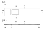
- FIG. 3A is a developed front view of the light shielding member shown in FIG. 1, and FIG. 3B is a cross-sectional view taken along line 3B-3B of FIG. 3A.
- FIG. 3B is a cross-sectional view taken along line 3B-3B of FIG. 3A.
- near-infrared light having a wavelength that is highly permeable to living organisms and absorbed by hemoglobin, as irradiation light to the visualization site where the artery is running.
- the extinction coefficient of oxyhemoglobin flowing in the artery is wavelength-dependent.
- 850 nm to 930 nm is a maximum (see http://www.frontech.fujitsu.com/services/products/palmsecure/what/interview/).
- the epidermis located on the outermost layer of the skin reflects visible light and near infrared light. Even near-infrared light with high biological permeability, 80% of the irradiated light is reflected by the epidermis, and about 10% of the light reaches 3 millimeters subcutaneously (Aitsu Yoshinaga, skin tissue multilayer structure modeling and Light propagation simulation, see Journal of the Japan Society of Mechanical Engineers 20111.7 Vol.114 No.1112 541).
- Puncture performed for the purpose of catheter examination and invasive arterial pressure measurement is generally performed for the radial artery and the brachial artery. For this reason, in the visualization device for puncture of an artery, the anatomical characteristics of the applied artery must be taken into consideration.
- the radial artery and brachial artery are surrounded by bone tissue and run 5-10 mm subcutaneously on the puncture skin surface.
- the skin surface of the puncture site should not be irradiated with near-infrared light. This is because the reflected near-infrared light invalidates the absorption image by the artery.
- the inventors of the present application have conducted extensive research based on the above findings, and as a result, have completed a technique for visualization for the purpose of puncturing the radial artery and the brachial artery.
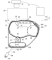
- FIG. 1 is a cross-sectional view showing an arterial visualization device 10 according to the first embodiment
- FIG. 2 is a cross-sectional view schematically showing a manner in which near-infrared light enters a living body
- 3A is a developed front view of the light shielding member 90 shown in FIG. 1
- FIG. 3B is a cross-sectional view taken along line 3B-3B in FIG. 3A.
- the arterial visualization device 10 includes a light source 32 that emits near-infrared light and includes a light source 32 that pierces an artery 21 that is running.
- An irradiation unit 30 that irradiates near-infrared light emitted from the light source 32 toward the skin surface 22, and a near-infrared light that seals the light source 32 and is pressed against the skin surface 22 on the back side and emitted from the light source 32.
- the light guide 40 formed from a material that suppresses reflection of near-infrared light on the surface of the skin surface 22 on the back side, and the skin surface 23 on the front side in the visualization site 20 while blocking visible light.
- the skin surface 23 on the front side and the imaging unit 60 are arranged apart from each other, and a work space 80 for performing puncturing is provided between the skin surface 23 on the front side and the imaging unit 60. .
- the arterial visualization device 10 according to the first embodiment will be described in detail.
- the visualization site 20 shown in the figure is, for example, the wrist portion where the radial artery as the puncturing artery 21 is running.
- the position of the hand is extended to the body side, with the palm facing up.
- the radial artery 21 is located 5-10 mm subcutaneously, and is surrounded by a radius 24, a carpal tunnel 25, a flexor tendon 26, and the like.
- Reference numeral 27 in the figure indicates the ulnar artery, and reference numeral 28 indicates the ulna.
- the irradiation unit 30 includes a chassis 31 formed in a hollow, substantially box shape, and a light source 32 that is disposed in the chassis 31 and emits near-infrared light.
- the chassis 31 is made of a metal material such as aluminum that does not transmit near infrared light.
- the visualization part 20 is placed from the upper surface side of the chassis 31.
- Near-infrared light emitted from the light source 32 is irradiated toward the dorsal skin surface 22 in the visualization site 20.
- the light source 32 for example, an LED that emits near-infrared light can be used.
- the near-infrared light to be irradiated preferably has a wavelength range of 840 to 950 nm. This is because when the wavelength is less than 840 nm, it is difficult to transmit the visualization site 20, and long-wavelength near-infrared light exceeding the wavelength of 950 nm is difficult to transmit due to absorption by water contained in the living body.
- the near-infrared light to be irradiated is more preferably in the wavelength range of 850-930 nm. Since the extinction coefficient of oxyhemoglobin flowing in the artery is maximized in the wavelength range of 850 to 930 nm, transmitted light with a reduced signal intensity can be obtained by the artery 21. As a result, a difference in contrast occurs between the transmitted light that has passed through the artery 21 and the transmitted light that has passed through the surrounding tissue, making it easier to visually recognize the artery.
- the near infrared light entering the living body is preferably a transmission method using pseudo-parallel light.
- a transmitted light image transmitted through the living tissue and an absorption image absorbed by the artery 21 are formed. Therefore, transmitted light that enters perpendicularly to the imaging surface is desirable.
- a light guide unit 40 that seals the light source 32 and is pressed against the skin surface 22 on the back side is disposed between the light source 32 and the visualization site 20.
- the light guide 40 is made of a material that transmits near infrared light emitted from the light source 32 and suppresses reflection of near infrared light on the surface of the skin surface 22 on the back side.
- the light guide unit 40 guides near infrared light from the light source 32 to the dorsal skin surface 22 and suppresses reflection of near infrared light on the surface of the skin surface 22. As a result, near infrared light can be efficiently incident on the dorsal skin surface 22 in the visualized region 20. Further, since the near-infrared light is incident on the dorsal skin surface 22, no near-infrared light is reflected on the surface of the front-side skin surface 23.
- the material for forming the light guide 40 is, of course, from the viewpoint of transmitting near-infrared light from the light source 32 to the dorsal skin surface 22, but is preferably a material having a high near-infrared light transmittance. Moreover, from the viewpoint of suppressing reflection of near-infrared light on the surface of the skin surface 22, it is desirable that the material for forming the light guide unit 40 has a refractive index close to that of a living body.
- the refractive index of the light guide 40 is preferably in the range from 1.33 which is the refractive index of water contained in a large amount in the living body to 1.44 which is the refractive index of collagen contained in a large amount in the living body.
- An example of a material for forming the light guide unit 40 is a silicone rubber having a high near-infrared light transmittance and a refractive index close to that of a living body, and a refractive index of 1.33-1.44. Can do. According to the light guide section 40 made of such a forming material, near infrared light can be efficiently incident on the skin surface 22 on the back side in the visualization site 20.
- the dorsal skin surface 22 is pressed to collapse the capillary network of the skin. Thereby, it can suppress that near infrared light is absorbed in the skin part into which near infrared light injects. As a result, the near-infrared light can be efficiently irradiated to the artery 21 located deeper than the capillary network, and the artery 21 can be visualized more clearly.
- the light guide 40 is preferably formed with a pressing portion 42 that protrudes toward the dorsal skin surface 22 and presses the dorsal skin surface 22. This is because it is easy to collapse the capillary network of the skin by locally pressing the skin surface 22 on the back side with the pressing portion 42. Thereby, it is possible to further suppress the absorption of the near infrared light in the skin portion where the near infrared light is incident, and it is possible to visualize the artery 21 more clearly.
- the shape of the compression part 42 is not particularly limited as long as the shape easily compresses the capillary network of the skin by pressing the skin surface 22 on the back side, and may be a hemispherical shape as illustrated. Further, the pressing portion 42 may have a shape having a plurality of convex portions in addition to the shape having one convex portion.
- the pressure for pressing the light guide 40 against the dorsal skin surface 22 is preferably 20-40 mmHg.
- the back skin surface 22 is pressed to collapse the capillary network of the skin, and the near infrared light is absorbed in the skin part where the near infrared light is incident. This is because it can be suppressed.
- a pressure sensor 43 is disposed between the rear side of the light source 32 and the chassis 31.
- the pressure sensor 43 detects the contact pressure that presses the light guide 40 against the dorsal skin surface 22.
- the method of pressure detection in the pressure sensor 43 is not particularly limited. For example, it is possible to apply a pressure sensor that detects pressure by reading a change in electrical resistance as a voltage signal, which is generated when the diaphragm is deflected by external pressure and a piezoresistive element formed on the diaphragm is distorted. .
- This type of pressure sensor directly captures the amount of diaphragm deflection as a change in the electrical resistance of the piezoresistive element, and thus has a simple element structure and many miniaturized ones.
- the contact pressure detected by the pressure sensor is displayed on the monitor 70 by a numerical value or an indicator bar.
- the contact pressure between the dorsal skin surface 22 and the light guide 40 can be adjusted to a range of 20-40 mmHg by adjusting the force for pressing the visualization site 20 against the light guide 40 while confirming this display. .
- the optical filter 50 can be inserted between the image pickup element in the camera 60 and the lens, or can be disposed in front of the camera 60. In order to visualize the artery 21 located 5-10 mm subcutaneously, it is preferable to block a component having a wavelength shorter than 840 nm.
- a near-infrared CCD camera that captures near-infrared light that has passed through the visualization part 20 and the optical filter 50, a CMOS camera, or the like is applied.
- the CCD camera is a camera composed of a Charge Coupled Device element
- the CMOS camera is a camera using a complementary metal oxide semiconductor.
- Data captured by a near-infrared CCD camera or the like is subjected to image processing and image analysis such as noise processing, edge processing, and contrast enhancement, and converted into image data to be displayed on the monitor 70.
- the monitor 70 is not particularly limited as long as an image captured by the camera 60 can be displayed.
- a desktop display or a head-mounted display may be used.
- the displayed image may be either monochrome or color.
- a medical worker such as an operator can accurately grasp the position and orientation of the artery 21 by viewing the image of the artery 21 displayed on the monitor 70.
- the arterial visualization device 10 of the present embodiment is intended to facilitate the puncture of the artery 21, it is necessary that the skin of the puncture part is open so that the puncture can be performed. Therefore, the skin surface 23 on the front side and the camera 60 are spaced apart. As a result, a working space 80 for puncturing is formed between the skin surface 23 on the front side and the camera 60.
- the distance between the skin surface 23 on the front side and the camera 60 can be set to an appropriate distance from the viewpoint of securing a sufficient work space 80. As an example, it is desirable to arrange the skin surface 23 on the front side and the camera 60 at a distance of 20 cm or more.
- the arterial visualization device 10 further includes a light shielding member 90 that covers the skin surface 23 on the front side.
- the light shielding member 90 includes a light shielding portion 91 formed of a material that blocks near-infrared light, and an observation window 92 having an opening for photographing the visualized portion 20. It has been.
- the light shielding member 90 is put on the skin surface 23 on the front side with the observation window 92 positioned right above the radial artery 21.
- near-infrared light can be transmitted only from the site of the puncture portion in the skin surface 23 on the front side, and visualization of the puncture artery 21 is ensured.
- a material that blocks near-infrared light for example, a light shielding rubber can be exemplified, but the material is not limited thereto.
- the light shielding member 90 is provided around the observation window 92 and includes a protruding portion 93 that protrudes from the light shielding portion 91.
- a protruding portion 93 that protrudes from the light shielding portion 91.
- hook-and-loop fasteners 95a and 95b generally called magic tape (registered trademark) are provided as a fixture 94 for fixing the visualization part 20 to the light guide unit 40 in a pressed state.
- the surface fastener 95a of the light shielding member 90 is detachably bonded to a surface fastener 95b attached to the chassis 31 side.
- the artery visualization device 10 of the first embodiment is (1)
- a light guide 40 is formed from a material that transmits near infrared light emitted from the light source 32 and suppresses reflection of near infrared light on the surface of the skin surface 22 on the back side.
- the light source 32 is sealed and the light guide 40 is pressed against the skin surface 22 on the back side, so that near-infrared light is not reflected on the surface of the skin surface 22 on the back side on which the near-infrared light is incident.
- the light guide 40 compresses the skin surface 22 on the back side to collapse the capillary network of the skin, and the near-infrared light is prevented from being absorbed in the skin portion where the near-infrared light is incident.
- the skin surface 23 on the front side and the imaging unit 60 are arranged apart from each other and the work space 80 for puncturing is provided between the skin surface 23 on the front side and the imaging unit 60, puncturing is performed without interfering with the puncturing technique.
- the artery 21 to be visualized can be visualized.
- the light guide unit 40 is formed with a pressing part 42 that protrudes toward the dorsal skin surface 22 and compresses the dorsal skin surface 22, the pressing unit 42 causes the dorsal skin surface 22 to be locally applied.
- the compression facilitates collapse of the capillary network of the skin. Thereby, it is possible to further suppress the absorption of the near infrared light in the skin portion where the near infrared light is incident, and it is possible to visualize the artery 21 more clearly.
- the light shielding portion 91 and the observation window 92 are provided and further includes a light shielding member 90 that covers the skin surface 23 on the front side, near infrared light can be transmitted only from the site of the puncture portion of the skin surface 23 on the front side. This makes it possible to visualize the artery 21 to be punctured.
- the artery 21 located 5 to 10 mm subcutaneous can be suitably visualized.
- the material forming the light guide 40 is a silicone rubber having a high near-infrared light transmittance and a refractive index close to that of a living body, and its refractive index is 1.33-1.44. The reflection of near infrared light on the surface of the skin surface 22 can be further suppressed.
- the dorsal skin surface 22 is pressed to collapse the capillary network of the skin, and near-infrared light is incident. It is possible to prevent near infrared light from being absorbed in the skin part.
- the radial artery 21 or the brachial artery When the artery to be visualized is the radial artery 21 or the brachial artery, the radial artery 21 or the brachial artery is visualized in the puncture performed for the purpose of catheter inspection or invasive arterial pressure measurement, and the puncture is performed reliably and easily. be able to.
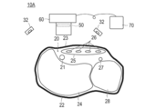
- FIG. 4 is a cross-sectional view showing an artery visualization device 11 according to the second embodiment.
- Members common to those in the first embodiment are denoted by the same reference numerals, and description thereof is partially omitted.
- the artery visualization device 11 irradiates near-infrared light emitted from the light source 32 toward the dorsal skin surface 22 in the visualization site 20.
- a light guide unit 40 that seals the light source 32 and is pressed against the skin surface 22 on the back side, an optical filter 50, a camera 60, a monitor 70, a work space 80, and a light shielding member 90.
- the second embodiment is different from the first embodiment in that it further includes a pressure adjustment unit 100 that can adjust the pressure for pressing the light guide unit 40 against the skin surface 22 on the back side.
- the light shielding member 90 is also different from the first embodiment in that the light shielding member 90 has a belt shape that can be wound around and attached to the visualization part 20.
- the light shielding member 90 of the second embodiment is provided with a light shielding part 91 that is formed of a material that blocks near-infrared light and can be wound around the visualization part 20, and an observation window 92 that is opened to image the visualization part 20. ing.
- the light shielding member 90 is placed on the skin surface 23 on the front side with the observation window 92 positioned immediately above the radial artery 21 and is further wound around the visualization site 20.
- By covering the light shielding member 90 near-infrared light can be transmitted only from the site of the puncture portion in the skin surface 23 on the front side, and visualization of the puncture artery 21 is ensured.
- a material that blocks near-infrared light for example, a light shielding rubber can be exemplified, but the material is not limited thereto.
- hook-and-loop fasteners 96a and 96b are provided as fixtures 94 that fix the visualization site 20 to the light guide unit 40 in a pressed state.
- the hook-and-loop fastener is provided with a first hook-and-loop fastener 96a provided at the rear-surface-side end portion of the light-shielding portion 91 and a second hook-and-loop fastener 96b provided at the front-surface-side end portion and detachably bonded to the first hook-and-loop fastener 96a. And have.
- the visualization site 20 is fixed in a state of being pressed against the light guide unit 40, and the position of the light shielding member 90 is shifted or detached when the artery is visualized. Can be prevented.
- the pressure adjusting unit 100 includes a balloon 101 that expands by injecting a fluid, and an injection unit 102 that injects a fluid into the balloon 101.
- the balloon 101 is formed of an inflatable rubber material, similar to a blood pressure measurement cuff.
- the injection unit 102 includes a hollow tube 103 connected to the balloon 101 and an air supply ball 104 that supplies air as a fluid to the balloon 101 via the hollow tube 103.
- the air supply ball 104 is provided with an operation unit 105 that operates a valve (not shown) that adjusts the air pressure in the balloon 101.
- a light source 32 is attached to the outer surface of the balloon 101 so as to face the dorsal skin surface 22.
- Reference numeral 106 in the drawing denotes a holding plate 106 that is attached to the balloon 101 and holds the balloon 101. By pressing the holding plate 106 on a table or the like via the light shielding portion 91, the posture of the visualization site 20 can be stabilized at the time of visualization of the artery.
- the pressure adjustment unit 100 adjusts the air pressure in the balloon 101 while checking the contact pressure detected by the pressure sensor 43 displayed on the monitor 70. Adjust.
- the pressure adjusting unit 100 the pressure for pressing the light guide unit 40 against the dorsal skin surface 22 can be easily and reliably adjusted to a desired range, for example, the range of 20-40 mmHg described above.
- the back skin surface 22 is pressed to collapse the capillary network of the skin, and the near infrared light is absorbed in the skin part where the near infrared light is incident. Can be suppressed.
- the arterial visualization device 11 of the second embodiment has the same effects as the arterial visualization device 10 of the first embodiment described above. Furthermore, the arterial visualization device 11 according to the second embodiment includes the pressure adjustment unit 100 that can adjust the pressure for pressing the light guide unit 40 against the skin surface 22 on the back side. The pressure applied to the skin surface 22 can be easily and reliably adjusted to a desired range.
- the arterial visualization device in which the display unit 70 is connected to the arterial imaging devices 120 and 121 including the irradiation unit 30, the light guide unit 40, the optical filter 50, and the imaging unit 60.
- the arterial imaging devices 120 and 121 may be connected to an existing display unit. In this case, simply by preparing the arterial imaging devices 120 and 121, an arterial visualization device that can favorably visualize the artery 21 to be punctured can be configured, which is advantageous in terms of cost.
- one LED having a light emission center wavelength of 850 nm (manufactured by Vishay, VSMY 7850X1) was used. A current of 1.75 Volts and 720 mA was passed through this LED.
- Liquid silicone rubber (Shin-Etsu Chemical Co., Ltd., Shin-Etsu Silicone One-Pack RTV Rubber “KE-441”) was used as the material of the light guide 40.
- the liquid silicone rubber used has a refractive index of 1.4.
- An optical filter 50 that blocks components having a wavelength shorter than 840 nm was inserted between the imaging element in the camera 60 and the lens.
- the air pressure in the balloon was adjusted by the pressure adjustment unit 100, and the pressure for pressing the compression part 42 of the light guide unit 40 against the dorsal skin surface 22 was adjusted to 40 mmHg.
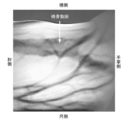
- the object of visualization is the left radial artery 21 of a 50-year-old male.
- near-infrared light was transmitted from the distal dorsal side of the forearm, and the distal palm side surface where the radial artery 21 was expected to travel was observed with a near-infrared high-sensitivity camera. Discrimination between the artery 21 and the vein was performed based on the presence or absence of blood vessel pulsation.
- Figure 5 shows the transmission image obtained.
- FIG. 6 is a cross-sectional view showing the arterial visualization device 10 ⁇ / b> A according to the comparative example.
- near-infrared light was irradiated toward the skin surface 23 on the front side in the visualization site 20, that is, the skin surface on the side where the puncture portion is present.
- reflected light having a reduced signal intensity is obtained by the artery 21. Therefore, a contrast is generated by the difference between the reflected light from the artery 21 and the reflected light from surrounding tissues, and a fluoroscopic image is obtained.
- the light source 32, the optical filter 50, and the camera 60 used the same thing as the experimental example mentioned above.
- Fig. 7 shows the image obtained.
- the image was taken by changing the light source 32 and changing the wavelength of near-infrared light in the range of 750-950 nm. However, the reflection of near-infrared light on the skin surface occurs in the same manner, so that the artery 21 cannot be visualized.
- Arterial visualization device 20 Visualization site, 21 radial artery, puncture artery, 22 dorsal skin surface, 23 Front skin surface, 24 ribs, 27 ulnar artery, 28 ulna, 30 Irradiation part, 31 chassis, 32 light sources, 40 light guide, 42 compression part, 43 Pressure sensor, 50 optical filters, 60 camera (imaging part), 70 Monitor (display part), 80 working space, 90 light shielding member, 91 shading part, 92 Observation window, 93 protrusion, 94 fixtures, 100 pressure regulator, 101 balloon, 102 injection part, 120, 121 Arterial imaging device.
Landscapes
- Health & Medical Sciences (AREA)
- Life Sciences & Earth Sciences (AREA)
- Surgery (AREA)
- General Health & Medical Sciences (AREA)
- Veterinary Medicine (AREA)
- Engineering & Computer Science (AREA)
- Biomedical Technology (AREA)
- Heart & Thoracic Surgery (AREA)
- Medical Informatics (AREA)
- Molecular Biology (AREA)
- Pathology (AREA)
- Animal Behavior & Ethology (AREA)
- Public Health (AREA)
- Physics & Mathematics (AREA)
- Biophysics (AREA)
- Nuclear Medicine, Radiotherapy & Molecular Imaging (AREA)
- Oral & Maxillofacial Surgery (AREA)
- Vascular Medicine (AREA)
- Optics & Photonics (AREA)
- Physical Education & Sports Medicine (AREA)
- Spectroscopy & Molecular Physics (AREA)
- Measuring Pulse, Heart Rate, Blood Pressure Or Blood Flow (AREA)
- Measurement Of The Respiration, Hearing Ability, Form, And Blood Characteristics Of Living Organisms (AREA)
- Investigating Or Analysing Materials By Optical Means (AREA)
Abstract
Description
前記光源を封止するとともに前記背側の皮膚面に押し付けられ、前記光源から出射された近赤外光を透過させるとともに前記背側の皮膚面の表面における近赤外光の反射を抑える材料から形成された導光部と、
可視光を遮断するとともに前記可視化部位における表側の皮膚面を透過した近赤外光を透過させる光学フィルターと、
前記光学フィルターを透過した近赤外光を受光し前記可視化部位を撮影する撮像部と、
前記撮像部によって撮影した画像を表示する表示部と、を有する。
図1は、第1の実施形態に係る動脈可視化装置10を示す断面図、図2は、近赤外光の生体内への射入様式を模式的に示す断面図である。また、図3(A)は、図1に示される遮光部材90を展開して示す正面図、図3(B)は、図3(A)の3B-3B線に沿う断面図である。
(1)光源32から出射された近赤外光を透過させるとともに背側の皮膚面22の表面における近赤外光の反射を抑える材料から導光部40を形成し、この導光部40によって光源32を封止するとともに導光部40を背側の皮膚面22に押し付け、近赤外光を入射する側である背側の皮膚面22の表面において近赤外光の反射を生じさせない。
図4は、第2の実施形態に係る動脈可視化装置11を示す断面図である。第1の実施形態と共通する部材には同一の符号を付し、その説明は一部省略する。
図4に示した動脈可視化装置11を用いて橈骨動脈21を可視化した実験結果について説明する。
図6は、対比例に係る動脈可視化装置10Aを示す断面図である。
20 可視化部位、
21 橈骨動脈、穿刺する動脈、
22 背側の皮膚面、
23 表側の皮膚面、
24 橈骨、
27 尺骨動脈、
28 尺骨、
30 照射部、
31 シャーシ、
32 光源、
40 導光部、
42 圧迫部、
43 圧力センサー、
50 光学フィルター、
60 カメラ(撮像部)、
70 モニター(表示部)、
80 作業空間、
90 遮光部材、
91 遮光部、
92 観察窓、
93 突出部、
94 固定具、
100 圧力調整部、
101 バルーン、
102 注入部、
120、121 動脈撮像装置。
Claims (11)
- 近赤外光を出射する光源を備え、穿刺する動脈が走行している可視化部位における背側の皮膚面に向けて前記光源から出射された近赤外光を照射する照射部と、
前記光源を封止するとともに前記背側の皮膚面に押し付けられ、前記光源から出射された近赤外光を透過させるとともに前記背側の皮膚面の表面における近赤外光の反射を抑える材料から形成された導光部と、
可視光を遮断するとともに前記可視化部位における表側の皮膚面を透過した近赤外光を透過させる光学フィルターと、
前記光学フィルターを透過した近赤外光を受光し前記可視化部位を撮影する撮像部と、
前記撮像部によって撮影した画像を表示する表示部と、を有する動脈可視化装置。 - 前記表側の皮膚面と前記撮像部とを離間して配置し、前記表側の皮膚面と前記撮像部との間に穿刺を行う作業空間を設けてなる、請求項1に記載の動脈可視化装置。
- 前記導光部は、前記背側の皮膚面に向けて突出して前記背側の皮膚面を圧迫する圧迫部が形成されてなる、請求項1または請求項2に記載の動脈可視化装置。
- 前記導光部を前記背側の皮膚面に押し付ける圧力を調整自在な圧力調整部をさらに有する、請求項1~請求項3のいずれか1つに記載の動脈可視化装置。
- 近赤外光を遮断する材料から形成された遮光部と、前記可視化部位を撮影する開口された観察窓とが設けられ、前記表側の皮膚面に被せられる遮光部材をさらに有する、請求項1~請求項4のいずれか1つに記載の動脈可視化装置。
- 前記遮光部材は、前記観察窓の周囲に設けられるとともに前記遮光部から突出する突出部を備え、前記突出部を前記表側の皮膚面に当接させることによって、前記表側の皮膚面のうち前記観察窓に臨む部位以外を透過した近赤外光が前記観察窓に混入することを遮断してなる、請求項5に記載の動脈可視化装置。
- 前記近赤外光は、波長840-950nmである、請求項1~請求項6のいずれか1つに記載の動脈可視化装置。
- 前記導光部を形成する材料は、近赤外光透過率が高く、かつ、屈折率が生体に近いシリコーンゴムであり、その屈折率が1.33-1.44である、請求項1~請求項7のいずれか1つに記載の動脈可視化装置。
- 前記導光部を前記背側の皮膚面に押し付ける圧力は、20-40mmHgである、請求項1~請求項8のいずれか1つに記載の動脈可視化装置。
- 可視化する動脈が橈骨動脈、または上腕動脈である、請求項1~請求項9のいずれか1つに記載の動脈可視化装置。
- 請求項1~10のいずれか1つに記載の動脈可視化装置に用いられる動脈撮像装置であって、前記照射部と、前記導光部と、前記光学フィルターと、前記撮像部と、を有する動脈撮像装置。
Priority Applications (5)
| Application Number | Priority Date | Filing Date | Title |
|---|---|---|---|
| JP2014518679A JP5626943B2 (ja) | 2012-05-29 | 2013-05-28 | 動脈可視化装置、および動脈撮像装置 |
| CA 2874401 CA2874401A1 (en) | 2012-05-29 | 2013-05-28 | Artery visualization device and artery imaging device |
| AU2013268517A AU2013268517A1 (en) | 2012-05-29 | 2013-05-28 | Artery visualization device and artery imaging device |
| US14/403,632 US10349886B2 (en) | 2012-05-29 | 2013-05-28 | Artery visualization device and artery imaging device |
| EP13796430.0A EP2856940B1 (en) | 2012-05-29 | 2013-05-28 | Artery imaging device, and artery visualization device and method |
Applications Claiming Priority (2)
| Application Number | Priority Date | Filing Date | Title |
|---|---|---|---|
| JP2012-121700 | 2012-05-29 | ||
| JP2012121700 | 2012-05-29 |
Publications (1)
| Publication Number | Publication Date |
|---|---|
| WO2013180126A1 true WO2013180126A1 (ja) | 2013-12-05 |
Family
ID=49673318
Family Applications (1)
| Application Number | Title | Priority Date | Filing Date |
|---|---|---|---|
| PCT/JP2013/064763 Ceased WO2013180126A1 (ja) | 2012-05-29 | 2013-05-28 | 動脈可視化装置、および動脈撮像装置 |
Country Status (6)
| Country | Link |
|---|---|
| US (1) | US10349886B2 (ja) |
| EP (1) | EP2856940B1 (ja) |
| JP (2) | JP5626943B2 (ja) |
| AU (1) | AU2013268517A1 (ja) |
| CA (1) | CA2874401A1 (ja) |
| WO (1) | WO2013180126A1 (ja) |
Cited By (4)
| Publication number | Priority date | Publication date | Assignee | Title |
|---|---|---|---|---|
| CN104799815A (zh) * | 2015-03-26 | 2015-07-29 | 山东大学 | 一种基于图像引导的血气采集装置及方法 |
| JP2019000723A (ja) * | 2018-10-11 | 2019-01-10 | 三星電子株式会社Samsung Electronics Co.,Ltd. | 生体情報取得装置及び腕時計端末 |
| JP2019088802A (ja) * | 2015-02-17 | 2019-06-13 | アムジエン・インコーポレーテツド | 固定及び/または戻りが真空によって支援された薬物送達装置 |
| JP2020505164A (ja) * | 2017-01-30 | 2020-02-20 | フレゼニウス メディカル ケア ドイッチェランド ゲゼルシャフト ミット ベシュレンクテル ハフツング | 血管を識別して操作するための装置及び対応する方法 |
Families Citing this family (24)
| Publication number | Priority date | Publication date | Assignee | Title |
|---|---|---|---|---|
| US11246913B2 (en) | 2005-02-03 | 2022-02-15 | Intarcia Therapeutics, Inc. | Suspension formulation comprising an insulinotropic peptide |
| EP2049081B1 (en) | 2006-08-09 | 2012-11-14 | Intarcia Therapeutics, Inc. | Osmotic delivery systems and piston assemblies |
| HRP20130259T1 (hr) | 2007-04-23 | 2013-04-30 | Intarcia Therapeutics, Inc. | Suspenzijske formulacije inzulinotropnih peptida i njihove uporabe |
| DK2240155T3 (da) | 2008-02-13 | 2012-09-17 | Intarcia Therapeutics Inc | Indretninger, formuleringer og fremgangsmåder til levering af flere gavnlige midler |
| SMT201700583T1 (it) | 2009-09-28 | 2018-01-11 | Intarcia Therapeutics Inc | Instaurazione e/o terminazione rapida di erogazione di farmaci in modo sostanzialmente stazionario |
| US20120208755A1 (en) | 2011-02-16 | 2012-08-16 | Intarcia Therapeutics, Inc. | Compositions, Devices and Methods of Use Thereof for the Treatment of Cancers |
| JP5626943B2 (ja) * | 2012-05-29 | 2014-11-19 | 国立大学法人高知大学 | 動脈可視化装置、および動脈撮像装置 |
| US9889085B1 (en) | 2014-09-30 | 2018-02-13 | Intarcia Therapeutics, Inc. | Therapeutic methods for the treatment of diabetes and related conditions for patients with high baseline HbA1c |
| WO2016182075A1 (ja) * | 2015-05-13 | 2016-11-17 | 株式会社プラス・メッド | 動脈可視化装置 |
| US10925639B2 (en) | 2015-06-03 | 2021-02-23 | Intarcia Therapeutics, Inc. | Implant placement and removal systems |
| KR102468133B1 (ko) * | 2016-02-29 | 2022-11-18 | 엘지전자 주식회사 | 발 정맥 인증 장치 |
| JP6061318B1 (ja) * | 2016-03-09 | 2017-01-18 | 国立大学法人高知大学 | 穿刺練習具 |
| RU2760007C2 (ru) | 2016-05-16 | 2021-11-22 | Интарсия Терапьютикс, Инк. | Полипептиды, селективные к рецепторам глюкагона, и способы их применения |
| USD840030S1 (en) | 2016-06-02 | 2019-02-05 | Intarcia Therapeutics, Inc. | Implant placement guide |
| USD860451S1 (en) | 2016-06-02 | 2019-09-17 | Intarcia Therapeutics, Inc. | Implant removal tool |
| CN110225762A (zh) | 2017-01-03 | 2019-09-10 | 因塔西亚制药公司 | 包括glp-1受体激动剂的连续施用和药物的共同施用的方法 |
| CN109419497B (zh) * | 2017-08-31 | 2021-12-17 | 中国科学院微电子研究所 | 基于热成像的关脉识别方法 |
| USD933219S1 (en) | 2018-07-13 | 2021-10-12 | Intarcia Therapeutics, Inc. | Implant removal tool and assembly |
| JP7674371B2 (ja) * | 2020-08-26 | 2025-05-09 | テルモ株式会社 | 血管可視化装置、血管穿刺システム及び観察窓部材 |
| WO2022044977A1 (ja) * | 2020-08-26 | 2022-03-03 | テルモ株式会社 | 血管可視化装置、血管穿刺システム及び観察窓部材 |
| JPWO2023153320A1 (ja) * | 2022-02-09 | 2023-08-17 | ||
| WO2023153319A1 (ja) * | 2022-02-09 | 2023-08-17 | テルモ株式会社 | 血管可視化装置、血管穿刺システム及び血管可視化システム |
| JP7728200B2 (ja) * | 2022-02-17 | 2025-08-22 | テルモ株式会社 | 血管可視化部材、血管可視化装置、血管穿刺システム及び血管可視化システム |
| CN115191953B (zh) * | 2022-09-08 | 2022-11-29 | 首都医科大学宣武医院 | 一种可视化注射系统 |
Citations (8)
| Publication number | Priority date | Publication date | Assignee | Title |
|---|---|---|---|---|
| US6424858B1 (en) * | 1998-11-12 | 2002-07-23 | John L. Williams | Apparatus and method for viewing vasculature of a human being |
| US6443928B1 (en) * | 2001-04-02 | 2002-09-03 | Raymond Francis | Vein scope and injection system |
| JP2004237051A (ja) * | 2003-02-06 | 2004-08-26 | Ogawa Hiroteru | 血管可視化方法ならびに装置 |
| JP2005191748A (ja) | 2003-12-24 | 2005-07-14 | Sony Corp | 撮像装置 |
| JP3144999U (ja) * | 2008-02-29 | 2008-09-25 | 久美子 宮田 | ベルト式採血用透光照明器 |
| JP2009532140A (ja) * | 2006-04-07 | 2009-09-10 | ノヴァリックス リミテッド | 静脈ナビゲーション装置 |
| JP2010148853A (ja) * | 2008-06-16 | 2010-07-08 | Norii Kk | 注射針誘導装置 |
| JP2011200374A (ja) * | 2010-03-25 | 2011-10-13 | Panasonic Corp | 光治療プローブ及び光治療装置 |
Family Cites Families (15)
| Publication number | Priority date | Publication date | Assignee | Title |
|---|---|---|---|---|
| US6606662B2 (en) * | 1997-06-11 | 2003-08-12 | Canon Kabushiki Kaisha | Portable terminal apparatus and communication method thereof |
| US6191599B1 (en) * | 1998-10-09 | 2001-02-20 | International Business Machines Corporation | IC device under test temperature control fixture |
| EP1074216B1 (en) * | 1999-02-22 | 2007-01-10 | Seiko Epson Corporation | Blood pressure measuring device and pulse wave detecting device |
| JP2002541894A (ja) * | 1999-04-21 | 2002-12-10 | 捷 ▲かん▼ | 無侵襲血圧測定方法と装置 |
| IL164563A0 (en) | 2004-10-13 | 2005-12-18 | Protech Medical Technologies L | Prostate treatment stent |
| US20080039715A1 (en) | 2004-11-04 | 2008-02-14 | Wilson David F | Three-dimensional optical guidance for catheter placement |
| WO2007105495A1 (ja) * | 2006-03-13 | 2007-09-20 | Olympus Medical Systems Corp. | 散乱媒質内部観察装置、撮像システム、撮像方法及び内視鏡装置 |
| JP4788526B2 (ja) * | 2006-08-30 | 2011-10-05 | 株式会社日立製作所 | 指静脈認証入力装置 |
| JP4827791B2 (ja) * | 2007-04-19 | 2011-11-30 | 日立マクセル株式会社 | 生体認証用撮像モジュール及び生体認証装置 |
| US20090000568A1 (en) * | 2007-06-28 | 2009-01-01 | Joshua Harrison Titcomb | Shock Absorbing Leash Attachment |
| US20090005685A1 (en) * | 2007-06-29 | 2009-01-01 | Canon Kabushiki Kaisha | Ultrasonic probe and inspection apparatus equipped with the ultrasonic probe |
| WO2009125349A2 (en) * | 2008-04-10 | 2009-10-15 | Cardiosigns Ltd. | Multi-sensor apparatus and method for monitoring of circulatory parameters |
| US8498694B2 (en) * | 2009-07-13 | 2013-07-30 | Entrotech, Inc. | Subcutaneous access device and related methods |
| JP5732692B2 (ja) * | 2010-08-02 | 2015-06-10 | セイコーエプソン株式会社 | 血圧検出装置及び血圧検出方法 |
| JP5626943B2 (ja) * | 2012-05-29 | 2014-11-19 | 国立大学法人高知大学 | 動脈可視化装置、および動脈撮像装置 |
-
2013
- 2013-05-28 JP JP2014518679A patent/JP5626943B2/ja active Active
- 2013-05-28 US US14/403,632 patent/US10349886B2/en active Active
- 2013-05-28 WO PCT/JP2013/064763 patent/WO2013180126A1/ja not_active Ceased
- 2013-05-28 CA CA 2874401 patent/CA2874401A1/en not_active Abandoned
- 2013-05-28 EP EP13796430.0A patent/EP2856940B1/en active Active
- 2013-05-28 AU AU2013268517A patent/AU2013268517A1/en not_active Abandoned
-
2014
- 2014-09-22 JP JP2014192946A patent/JP5946103B2/ja active Active
Patent Citations (8)
| Publication number | Priority date | Publication date | Assignee | Title |
|---|---|---|---|---|
| US6424858B1 (en) * | 1998-11-12 | 2002-07-23 | John L. Williams | Apparatus and method for viewing vasculature of a human being |
| US6443928B1 (en) * | 2001-04-02 | 2002-09-03 | Raymond Francis | Vein scope and injection system |
| JP2004237051A (ja) * | 2003-02-06 | 2004-08-26 | Ogawa Hiroteru | 血管可視化方法ならびに装置 |
| JP2005191748A (ja) | 2003-12-24 | 2005-07-14 | Sony Corp | 撮像装置 |
| JP2009532140A (ja) * | 2006-04-07 | 2009-09-10 | ノヴァリックス リミテッド | 静脈ナビゲーション装置 |
| JP3144999U (ja) * | 2008-02-29 | 2008-09-25 | 久美子 宮田 | ベルト式採血用透光照明器 |
| JP2010148853A (ja) * | 2008-06-16 | 2010-07-08 | Norii Kk | 注射針誘導装置 |
| JP2011200374A (ja) * | 2010-03-25 | 2011-10-13 | Panasonic Corp | 光治療プローブ及び光治療装置 |
Non-Patent Citations (2)
| Title |
|---|
| See also references of EP2856940A4 * |
| YOSHIHISA AIZU: "Skin Tissue Multilayer Structure Modeling", JOURNAL OF JAPAN SOCIETY OF MECHANICAL ENGINEERS, vol. 114, no. 1112, July 2011 (2011-07-01), pages 541 |
Cited By (7)
| Publication number | Priority date | Publication date | Assignee | Title |
|---|---|---|---|---|
| JP2019088802A (ja) * | 2015-02-17 | 2019-06-13 | アムジエン・インコーポレーテツド | 固定及び/または戻りが真空によって支援された薬物送達装置 |
| US11517663B2 (en) | 2015-02-17 | 2022-12-06 | Amgen Inc. | Drug delivery device with vacuum assisted securement and/or feedback |
| CN104799815A (zh) * | 2015-03-26 | 2015-07-29 | 山东大学 | 一种基于图像引导的血气采集装置及方法 |
| JP2020505164A (ja) * | 2017-01-30 | 2020-02-20 | フレゼニウス メディカル ケア ドイッチェランド ゲゼルシャフト ミット ベシュレンクテル ハフツング | 血管を識別して操作するための装置及び対応する方法 |
| US11510616B2 (en) | 2017-01-30 | 2022-11-29 | Fresenius Medical Care Deutschland Gmbh | Apparatus for identifying and manipulating a blood vessel, and corresponding method |
| JP7254702B2 (ja) | 2017-01-30 | 2023-04-10 | フレゼニウス メディカル ケア ドイッチェランド ゲゼルシャフト ミット ベシュレンクテル ハフツング | 血管を識別して操作するための装置及び対応する方法 |
| JP2019000723A (ja) * | 2018-10-11 | 2019-01-10 | 三星電子株式会社Samsung Electronics Co.,Ltd. | 生体情報取得装置及び腕時計端末 |
Also Published As
| Publication number | Publication date |
|---|---|
| JP5946103B2 (ja) | 2016-07-05 |
| EP2856940B1 (en) | 2020-05-06 |
| EP2856940A4 (en) | 2016-03-02 |
| JP5626943B2 (ja) | 2014-11-19 |
| JPWO2013180126A1 (ja) | 2016-01-21 |
| AU2013268517A1 (en) | 2015-01-22 |
| JP2015033585A (ja) | 2015-02-19 |
| US10349886B2 (en) | 2019-07-16 |
| US20150133791A1 (en) | 2015-05-14 |
| CA2874401A1 (en) | 2013-12-05 |
| EP2856940A1 (en) | 2015-04-08 |
Similar Documents
| Publication | Publication Date | Title |
|---|---|---|
| JP5946103B2 (ja) | 動脈可視化方法、動脈可視化装置、および動脈撮像装置 | |
| US11033207B2 (en) | Dynamic optical tomographic imaging devices methods and systems | |
| EP3675723B1 (en) | Multi-spectral physiologic visualization (mspv) using laser imaging methods and systems for blood flow and perfusion imaging and quantification in an endoscopic design | |
| TWI637727B (zh) | 用於進行經腹胎兒血氧飽和度及/或經腹胎兒脈搏血氧飽和度監測之系統、裝置及方法 | |
| US9743875B2 (en) | Automated vessel puncture device using three-dimensional(3D) near infrared (NIR) imaging and a robotically driven needle | |
| KR101647022B1 (ko) | 의료 영상 획득 장치 및 방법 | |
| EP1066791A2 (en) | Method and apparatus for detecting electro-magnetic reflection from biological tissue | |
| US20060173351A1 (en) | System and method for inserting a needle into a blood vessel | |
| US9974480B2 (en) | Artery visualization device | |
| US20100168584A1 (en) | Biological observation apparatus, biological observation method, and endoscopic apparatus | |
| JP2000316866A (ja) | 血管の視認方法及び血管の視認装置 | |
| KR20160089355A (ko) | 미리 결정된 생물학적 구조체의 비침습적 검출 디바이스 | |
| JP2007522869A (ja) | 埋込構造物の画像化 | |
| JP2011160891A (ja) | 静脈可視化装置 | |
| JP4331959B2 (ja) | 血管注射補助装置 | |
| US20060155194A1 (en) | Method for detecting occlusions and leakages in subcutaneous blood vessels | |
| CN204618246U (zh) | 一种非接触式静脉血氧饱和度成像装置 | |
| Shahzad et al. | A review on subcutaneous veins localization using imaging techniques | |
| Nowara et al. | Seeing beneath the skin with computational photography | |
| May et al. | Real time vein visualization using near-infrared imaging | |
| KR101635735B1 (ko) | 코 또는 그 주변의 혈관을 가시화하는 혈관 가시화 장치 및 방법 | |
| Tobisawa et al. | Injection assist system with surface and transillumination images | |
| CN114041737B (zh) | 应用于内窥镜的成像装置 | |
| CN114788683A (zh) | 信息获取装置 | |
| JP2016112220A (ja) | イメージング装置 |
Legal Events
| Date | Code | Title | Description |
|---|---|---|---|
| 121 | Ep: the epo has been informed by wipo that ep was designated in this application |
Ref document number: 13796430 Country of ref document: EP Kind code of ref document: A1 |
|
| DPE1 | Request for preliminary examination filed after expiration of 19th month from priority date (pct application filed from 20040101) | ||
| ENP | Entry into the national phase |
Ref document number: 2014518679 Country of ref document: JP Kind code of ref document: A |
|
| WWE | Wipo information: entry into national phase |
Ref document number: 2013796430 Country of ref document: EP |
|
| ENP | Entry into the national phase |
Ref document number: 2874401 Country of ref document: CA |
|
| WWE | Wipo information: entry into national phase |
Ref document number: 14403632 Country of ref document: US |
|
| NENP | Non-entry into the national phase |
Ref country code: DE |
|
| ENP | Entry into the national phase |
Ref document number: 2013268517 Country of ref document: AU Date of ref document: 20130528 Kind code of ref document: A |