WO2013183105A1 - 受電装置および送電装置 - Google Patents
受電装置および送電装置 Download PDFInfo
- Publication number
- WO2013183105A1 WO2013183105A1 PCT/JP2012/064388 JP2012064388W WO2013183105A1 WO 2013183105 A1 WO2013183105 A1 WO 2013183105A1 JP 2012064388 W JP2012064388 W JP 2012064388W WO 2013183105 A1 WO2013183105 A1 WO 2013183105A1
- Authority
- WO
- WIPO (PCT)
- Prior art keywords
- coil
- power
- power transmission
- capacitor
- unit
- Prior art date
- Legal status (The legal status is an assumption and is not a legal conclusion. Google has not performed a legal analysis and makes no representation as to the accuracy of the status listed.)
- Ceased
Links
Images











Classifications
-
- B—PERFORMING OPERATIONS; TRANSPORTING
- B60—VEHICLES IN GENERAL
- B60L—PROPULSION OF ELECTRICALLY-PROPELLED VEHICLES; SUPPLYING ELECTRIC POWER FOR AUXILIARY EQUIPMENT OF ELECTRICALLY-PROPELLED VEHICLES; ELECTRODYNAMIC BRAKE SYSTEMS FOR VEHICLES IN GENERAL; MAGNETIC SUSPENSION OR LEVITATION FOR VEHICLES; MONITORING OPERATING VARIABLES OF ELECTRICALLY-PROPELLED VEHICLES; ELECTRIC SAFETY DEVICES FOR ELECTRICALLY-PROPELLED VEHICLES
- B60L53/00—Methods of charging batteries, specially adapted for electric vehicles; Charging stations or on-board charging equipment therefor; Exchange of energy storage elements in electric vehicles
- B60L53/10—Methods of charging batteries, specially adapted for electric vehicles; Charging stations or on-board charging equipment therefor; Exchange of energy storage elements in electric vehicles characterised by the energy transfer between the charging station and the vehicle
- B60L53/12—Inductive energy transfer
- B60L53/122—Circuits or methods for driving the primary coil, e.g. supplying electric power to the coil
-
- B—PERFORMING OPERATIONS; TRANSPORTING
- B60—VEHICLES IN GENERAL
- B60L—PROPULSION OF ELECTRICALLY-PROPELLED VEHICLES; SUPPLYING ELECTRIC POWER FOR AUXILIARY EQUIPMENT OF ELECTRICALLY-PROPELLED VEHICLES; ELECTRODYNAMIC BRAKE SYSTEMS FOR VEHICLES IN GENERAL; MAGNETIC SUSPENSION OR LEVITATION FOR VEHICLES; MONITORING OPERATING VARIABLES OF ELECTRICALLY-PROPELLED VEHICLES; ELECTRIC SAFETY DEVICES FOR ELECTRICALLY-PROPELLED VEHICLES
- B60L53/00—Methods of charging batteries, specially adapted for electric vehicles; Charging stations or on-board charging equipment therefor; Exchange of energy storage elements in electric vehicles
- B60L53/10—Methods of charging batteries, specially adapted for electric vehicles; Charging stations or on-board charging equipment therefor; Exchange of energy storage elements in electric vehicles characterised by the energy transfer between the charging station and the vehicle
- B60L53/12—Inductive energy transfer
-
- B—PERFORMING OPERATIONS; TRANSPORTING
- B60—VEHICLES IN GENERAL
- B60L—PROPULSION OF ELECTRICALLY-PROPELLED VEHICLES; SUPPLYING ELECTRIC POWER FOR AUXILIARY EQUIPMENT OF ELECTRICALLY-PROPELLED VEHICLES; ELECTRODYNAMIC BRAKE SYSTEMS FOR VEHICLES IN GENERAL; MAGNETIC SUSPENSION OR LEVITATION FOR VEHICLES; MONITORING OPERATING VARIABLES OF ELECTRICALLY-PROPELLED VEHICLES; ELECTRIC SAFETY DEVICES FOR ELECTRICALLY-PROPELLED VEHICLES
- B60L53/00—Methods of charging batteries, specially adapted for electric vehicles; Charging stations or on-board charging equipment therefor; Exchange of energy storage elements in electric vehicles
- B60L53/10—Methods of charging batteries, specially adapted for electric vehicles; Charging stations or on-board charging equipment therefor; Exchange of energy storage elements in electric vehicles characterised by the energy transfer between the charging station and the vehicle
- B60L53/12—Inductive energy transfer
- B60L53/124—Detection or removal of foreign bodies
-
- B—PERFORMING OPERATIONS; TRANSPORTING
- B60—VEHICLES IN GENERAL
- B60L—PROPULSION OF ELECTRICALLY-PROPELLED VEHICLES; SUPPLYING ELECTRIC POWER FOR AUXILIARY EQUIPMENT OF ELECTRICALLY-PROPELLED VEHICLES; ELECTRODYNAMIC BRAKE SYSTEMS FOR VEHICLES IN GENERAL; MAGNETIC SUSPENSION OR LEVITATION FOR VEHICLES; MONITORING OPERATING VARIABLES OF ELECTRICALLY-PROPELLED VEHICLES; ELECTRIC SAFETY DEVICES FOR ELECTRICALLY-PROPELLED VEHICLES
- B60L53/00—Methods of charging batteries, specially adapted for electric vehicles; Charging stations or on-board charging equipment therefor; Exchange of energy storage elements in electric vehicles
- B60L53/10—Methods of charging batteries, specially adapted for electric vehicles; Charging stations or on-board charging equipment therefor; Exchange of energy storage elements in electric vehicles characterised by the energy transfer between the charging station and the vehicle
- B60L53/12—Inductive energy transfer
- B60L53/126—Methods for pairing a vehicle and a charging station, e.g. establishing a one-to-one relation between a wireless power transmitter and a wireless power receiver
-
- H—ELECTRICITY
- H01—ELECTRIC ELEMENTS
- H01F—MAGNETS; INDUCTANCES; TRANSFORMERS; SELECTION OF MATERIALS FOR THEIR MAGNETIC PROPERTIES
- H01F27/00—Details of transformers or inductances, in general
- H01F27/02—Casings
- H01F27/025—Constructional details relating to cooling
-
- H—ELECTRICITY
- H01—ELECTRIC ELEMENTS
- H01F—MAGNETS; INDUCTANCES; TRANSFORMERS; SELECTION OF MATERIALS FOR THEIR MAGNETIC PROPERTIES
- H01F27/00—Details of transformers or inductances, in general
- H01F27/08—Cooling; Ventilating
- H01F27/085—Cooling by ambient air
-
- H—ELECTRICITY
- H01—ELECTRIC ELEMENTS
- H01F—MAGNETS; INDUCTANCES; TRANSFORMERS; SELECTION OF MATERIALS FOR THEIR MAGNETIC PROPERTIES
- H01F27/00—Details of transformers or inductances, in general
- H01F27/24—Magnetic cores
- H01F27/26—Fastening parts of the core together; Fastening or mounting the core on casing or support
- H01F27/266—Fastening or mounting the core on casing or support
-
- H—ELECTRICITY
- H01—ELECTRIC ELEMENTS
- H01F—MAGNETS; INDUCTANCES; TRANSFORMERS; SELECTION OF MATERIALS FOR THEIR MAGNETIC PROPERTIES
- H01F27/00—Details of transformers or inductances, in general
- H01F27/28—Coils; Windings; Conductive connections
- H01F27/32—Insulating of coils, windings, or parts thereof
-
- H—ELECTRICITY
- H01—ELECTRIC ELEMENTS
- H01F—MAGNETS; INDUCTANCES; TRANSFORMERS; SELECTION OF MATERIALS FOR THEIR MAGNETIC PROPERTIES
- H01F38/00—Adaptations of transformers or inductances for specific applications or functions
- H01F38/14—Inductive couplings
-
- H—ELECTRICITY
- H02—GENERATION; CONVERSION OR DISTRIBUTION OF ELECTRIC POWER
- H02J—ELECTRIC POWER NETWORKS; CIRCUIT ARRANGEMENTS OR SYSTEMS FOR SUPPLYING OR DISTRIBUTING ELECTRIC POWER; SYSTEMS FOR STORING ELECTRIC ENERGY
- H02J50/00—Circuit arrangements or systems for wireless supply or distribution of electric power
- H02J50/005—Mechanical details of housing or structure aiming to accommodate the power transfer means, e.g. mechanical integration of coils, antennas or transducers into emitting or receiving devices
-
- H—ELECTRICITY
- H02—GENERATION; CONVERSION OR DISTRIBUTION OF ELECTRIC POWER
- H02J—ELECTRIC POWER NETWORKS; CIRCUIT ARRANGEMENTS OR SYSTEMS FOR SUPPLYING OR DISTRIBUTING ELECTRIC POWER; SYSTEMS FOR STORING ELECTRIC ENERGY
- H02J50/00—Circuit arrangements or systems for wireless supply or distribution of electric power
- H02J50/10—Circuit arrangements or systems for wireless supply or distribution of electric power using inductive coupling
-
- H—ELECTRICITY
- H02—GENERATION; CONVERSION OR DISTRIBUTION OF ELECTRIC POWER
- H02J—ELECTRIC POWER NETWORKS; CIRCUIT ARRANGEMENTS OR SYSTEMS FOR SUPPLYING OR DISTRIBUTING ELECTRIC POWER; SYSTEMS FOR STORING ELECTRIC ENERGY
- H02J50/00—Circuit arrangements or systems for wireless supply or distribution of electric power
- H02J50/10—Circuit arrangements or systems for wireless supply or distribution of electric power using inductive coupling
- H02J50/12—Circuit arrangements or systems for wireless supply or distribution of electric power using inductive coupling of the resonant type
-
- H—ELECTRICITY
- H02—GENERATION; CONVERSION OR DISTRIBUTION OF ELECTRIC POWER
- H02J—ELECTRIC POWER NETWORKS; CIRCUIT ARRANGEMENTS OR SYSTEMS FOR SUPPLYING OR DISTRIBUTING ELECTRIC POWER; SYSTEMS FOR STORING ELECTRIC ENERGY
- H02J50/00—Circuit arrangements or systems for wireless supply or distribution of electric power
- H02J50/70—Circuit arrangements or systems for wireless supply or distribution of electric power involving the reduction of electric, magnetic or electromagnetic leakage fields
-
- H—ELECTRICITY
- H02—GENERATION; CONVERSION OR DISTRIBUTION OF ELECTRIC POWER
- H02J—ELECTRIC POWER NETWORKS; CIRCUIT ARRANGEMENTS OR SYSTEMS FOR SUPPLYING OR DISTRIBUTING ELECTRIC POWER; SYSTEMS FOR STORING ELECTRIC ENERGY
- H02J7/00—Circuit arrangements for charging or discharging batteries or for supplying loads from batteries
- H02J7/40—Circuit arrangements for charging or discharging batteries or for supplying loads from batteries characterised by the exchange of charge or discharge related data
- H02J7/47—Arrangements for checking compatibility or authentication between one component, e.g. a battery or a battery charger, and another component, e.g. a power source
-
- H—ELECTRICITY
- H02—GENERATION; CONVERSION OR DISTRIBUTION OF ELECTRIC POWER
- H02J—ELECTRIC POWER NETWORKS; CIRCUIT ARRANGEMENTS OR SYSTEMS FOR SUPPLYING OR DISTRIBUTING ELECTRIC POWER; SYSTEMS FOR STORING ELECTRIC ENERGY
- H02J7/00—Circuit arrangements for charging or discharging batteries or for supplying loads from batteries
- H02J7/70—Circuit arrangements for charging or discharging batteries or for supplying loads from batteries characterised by the mechanical construction
-
- H—ELECTRICITY
- H02—GENERATION; CONVERSION OR DISTRIBUTION OF ELECTRIC POWER
- H02J—ELECTRIC POWER NETWORKS; CIRCUIT ARRANGEMENTS OR SYSTEMS FOR SUPPLYING OR DISTRIBUTING ELECTRIC POWER; SYSTEMS FOR STORING ELECTRIC ENERGY
- H02J2105/00—Networks for supplying or distributing electric power characterised by their spatial reach or by the load
- H02J2105/30—Networks for supplying or distributing electric power characterised by their spatial reach or by the load the load networks being external to vehicles, i.e. exchanging power with vehicles
- H02J2105/33—Networks for supplying or distributing electric power characterised by their spatial reach or by the load the load networks being external to vehicles, i.e. exchanging power with vehicles exchanging power with road vehicles
- H02J2105/37—Networks for supplying or distributing electric power characterised by their spatial reach or by the load the load networks being external to vehicles, i.e. exchanging power with vehicles exchanging power with road vehicles exchanging power with electric vehicles [EV] or with hybrid electric vehicles [HEV]
-
- Y—GENERAL TAGGING OF NEW TECHNOLOGICAL DEVELOPMENTS; GENERAL TAGGING OF CROSS-SECTIONAL TECHNOLOGIES SPANNING OVER SEVERAL SECTIONS OF THE IPC; TECHNICAL SUBJECTS COVERED BY FORMER USPC CROSS-REFERENCE ART COLLECTIONS [XRACs] AND DIGESTS
- Y02—TECHNOLOGIES OR APPLICATIONS FOR MITIGATION OR ADAPTATION AGAINST CLIMATE CHANGE
- Y02T—CLIMATE CHANGE MITIGATION TECHNOLOGIES RELATED TO TRANSPORTATION
- Y02T10/00—Road transport of goods or passengers
- Y02T10/60—Other road transportation technologies with climate change mitigation effect
- Y02T10/70—Energy storage systems for electromobility, e.g. batteries
-
- Y—GENERAL TAGGING OF NEW TECHNOLOGICAL DEVELOPMENTS; GENERAL TAGGING OF CROSS-SECTIONAL TECHNOLOGIES SPANNING OVER SEVERAL SECTIONS OF THE IPC; TECHNICAL SUBJECTS COVERED BY FORMER USPC CROSS-REFERENCE ART COLLECTIONS [XRACs] AND DIGESTS
- Y02—TECHNOLOGIES OR APPLICATIONS FOR MITIGATION OR ADAPTATION AGAINST CLIMATE CHANGE
- Y02T—CLIMATE CHANGE MITIGATION TECHNOLOGIES RELATED TO TRANSPORTATION
- Y02T10/00—Road transport of goods or passengers
- Y02T10/60—Other road transportation technologies with climate change mitigation effect
- Y02T10/7072—Electromobility specific charging systems or methods for batteries, ultracapacitors, supercapacitors or double-layer capacitors
-
- Y—GENERAL TAGGING OF NEW TECHNOLOGICAL DEVELOPMENTS; GENERAL TAGGING OF CROSS-SECTIONAL TECHNOLOGIES SPANNING OVER SEVERAL SECTIONS OF THE IPC; TECHNICAL SUBJECTS COVERED BY FORMER USPC CROSS-REFERENCE ART COLLECTIONS [XRACs] AND DIGESTS
- Y02—TECHNOLOGIES OR APPLICATIONS FOR MITIGATION OR ADAPTATION AGAINST CLIMATE CHANGE
- Y02T—CLIMATE CHANGE MITIGATION TECHNOLOGIES RELATED TO TRANSPORTATION
- Y02T90/00—Enabling technologies or technologies with a potential or indirect contribution to GHG emissions mitigation
- Y02T90/10—Technologies relating to charging of electric vehicles
- Y02T90/12—Electric charging stations
-
- Y—GENERAL TAGGING OF NEW TECHNOLOGICAL DEVELOPMENTS; GENERAL TAGGING OF CROSS-SECTIONAL TECHNOLOGIES SPANNING OVER SEVERAL SECTIONS OF THE IPC; TECHNICAL SUBJECTS COVERED BY FORMER USPC CROSS-REFERENCE ART COLLECTIONS [XRACs] AND DIGESTS
- Y02—TECHNOLOGIES OR APPLICATIONS FOR MITIGATION OR ADAPTATION AGAINST CLIMATE CHANGE
- Y02T—CLIMATE CHANGE MITIGATION TECHNOLOGIES RELATED TO TRANSPORTATION
- Y02T90/00—Enabling technologies or technologies with a potential or indirect contribution to GHG emissions mitigation
- Y02T90/10—Technologies relating to charging of electric vehicles
- Y02T90/14—Plug-in electric vehicles
Definitions
- the present invention relates to a power reception device and a power transmission device.
- a non-contact power feeding device described in Japanese Patent Application Laid-Open No. 2011-50127 includes a power receiving unit and a power transmitting unit, and each of the power transmitting unit and the power receiving unit is mounted on an H-shaped core and the core. Including a coil.
- the core includes two magnetic pole portions and a narrow coiled portion formed between the two magnetic pole portions and wound with a coil.
- the two magnetic pole portions are formed so as to be line symmetric with respect to a symmetry axis passing through the center of the narrow coiled portion and perpendicular to the two magnetic pole portions, and the core is symmetric with respect to the symmetry axis. It is formed to have an H shape.
- the temperature of the coil of the power reception unit, the temperature of the coil of the power transmission unit, and the like increase.
- the power receiving device including the power receiving unit as described above needs to include a cooling device for cooling the power receiving unit.
- a power transmission device including the above-described power transmission unit needs to include a cooling device that cools the power transmission unit.
- the conventional power receiving device and power transmitting device have a problem that the device itself is likely to be large.
- the present invention has been made in view of the above problems, and a first object of the present invention is to provide a power receiving device that can cool the power receiving unit satisfactorily while suppressing an increase in size of the device. That is.
- the second object is to provide a power transmission device capable of cooling the power transmission unit satisfactorily while suppressing an increase in size of the device.
- the power receiving device is a power receiving device that receives power in a non-contact manner from a power transmission unit including a first coil.
- the power receiving device includes a housing having a housing portion formed therein, a core disposed in the housing, a second coil disposed in the housing, the second coil provided in the core, and the first coil.
- An electric device connected to the two coils, an inner surface of the housing and the second coil, an insulating member disposed between the inner surface of the housing and the electric device, and a refrigerant in circulation. 2 coils and a cooling device for cooling the electrical equipment.
- the second coil and the electric device are attached to the inner surface of the casing with an insulating member interposed therebetween.
- the electric device is disposed upstream of the second coil in the refrigerant flow direction.
- the electrical device includes a capacitor connected to the second coil and a rectifier that rectifies the current received by the second coil.
- the rectifier is disposed upstream of the capacitor in the refrigerant flow direction.
- the capacitor is disposed upstream of the second coil in the refrigerant flow direction.
- the electrical device includes a capacitor connected to the second coil and a rectifier that rectifies the current received by the second coil.
- the capacitor is arranged upstream of the rectifier in the refrigerant flow direction.
- the rectifier is disposed upstream of the second coil in the refrigerant flow direction.
- the second coil is formed so as to surround the first winding shaft.
- the core is formed at a first shaft portion around which the second coil is wound, and a first end portion of the first shaft portion, and extends in a first intersecting direction intersecting a direction in which the first winding shaft extends.
- a magnetic pole part and a second magnetic pole part formed at the second end of the first shaft part and extending in the first intersecting direction are included.
- the width of the first shaft portion in the first intersecting direction is shorter than the length of the first magnetic pole portion and the length of the second magnetic pole portion in the first intersecting direction.
- the first central portion located in the center of the first magnetic pole portion in the first cross direction and the second central portion located in the center of the second magnetic pole portion in the first cross direction are the first axis in the first cross direction. It is located on one side in the first intersecting direction from the third central part located in the center of the part.
- the electric device is disposed on one side in the first intersecting direction with respect to the first shaft portion, and is disposed between the first magnetic pole portion and the second magnetic pole portion.
- the cooling device supplies a refrigerant into the housing.
- the second coil is formed so as to surround the first winding shaft.
- the cooling device supplies the refrigerant in a first intersecting direction that intersects a direction in which the first winding axis extends.
- the casing is sealed.
- the second coil and the capacitor connected to the second coil form a power receiving unit that receives power from the power transmitting unit in a contactless manner.
- the difference between the natural frequency of the power transmission unit and the natural frequency of the power reception unit is 10% or less of the natural frequency of the power reception unit.
- the second coil and the capacitor connected to the second coil form a power receiving unit that receives power from the power transmitting unit in a contactless manner.
- the coupling coefficient between the power reception unit and the power transmission unit is 0.1 or less.
- the second coil and the capacitor connected to the second coil form a power receiving unit that receives power from the power transmitting unit in a contactless manner.
- the power reception unit is formed between at least one of a magnetic field formed between the power reception unit and the power transmission unit and oscillating at a specific frequency, and an electric field formed between the power reception unit and the power transmission unit and oscillating at a specific frequency. Receives power from the power transmission unit.
- the power transmission device is a power transmission device that transmits power in a non-contact manner to a power receiving unit including a first coil.
- the power transmission device includes a housing having a housing portion formed outside, a core disposed in the housing, a first coil disposed in the housing, disposed in the core, and disposed in the housing.
- An electric device connected to one coil, an insulating member disposed between the inner surface of the housing and the first coil, an insulating member disposed between the inner surface of the housing and the electric device, and a refrigerant. 1 coil and a cooling device for cooling the electrical equipment.
- the first coil and the electric device are attached to the inner surface of the casing with an insulating member interposed therebetween.
- the electric device is disposed upstream of the first coil in the refrigerant flow direction.
- the electrical device includes a capacitor connected to the first coil.
- the first coil is formed so as to surround the periphery of the second winding axis.
- the core is formed at a second shaft portion around which the first coil is wound and a third end portion of the second shaft portion, and extends in a second intersecting direction intersecting with the direction in which the second winding shaft extends.
- a magnetic pole part and a fourth magnetic pole part formed at the fourth end of the second shaft part and extending in the second crossing direction are included.
- the width of the second shaft portion in the second intersecting direction is shorter than the length of the third magnetic pole portion and the length of the fourth magnetic pole portion in the second intersecting direction.
- the fourth central part located at the center of the third magnetic pole part in the second crossing direction and the fifth central part located at the center of the fourth magnetic pole part in the second crossing direction are the second axis in the second crossing direction. It is located on the one side in the second crossing direction from the sixth central part located in the center of the part.
- the electric device is disposed on one side in the second intersecting direction with respect to the second shaft portion, and is disposed between the third magnetic pole portion and the fourth magnetic pole portion.
- the cooling device supplies a refrigerant into the housing.
- the first coil is formed so as to surround the periphery of the second winding axis.
- the cooling device supplies the refrigerant in a second intersecting direction that intersects a direction in which the second winding axis extends.
- the casing is sealed.
- the first coil and the capacitor connected to the first coil form a power transmission unit that transmits power to the power reception unit in a contactless manner.
- the difference between the natural frequency of the power transmission unit and the natural frequency of the power reception unit is 10% or less of the natural frequency of the power reception unit.
- the first coil and the capacitor connected to the first coil form a power transmission unit that transmits power to the power reception unit in a contactless manner.
- the coupling coefficient between the power reception unit and the power transmission unit is 0.1 or less.
- the first coil and the capacitor connected to the first coil form a power transmission unit that transmits power to the power reception unit in a contactless manner.
- the power transmission unit is formed between at least one of a magnetic field formed between the power reception unit and the power transmission unit and oscillating at a specific frequency, and an electric field formed between the power reception unit and the power transmission unit and oscillating at a specific frequency. Power is transmitted to the power receiving unit.
- the power receiving device it is possible to satisfactorily cool the power receiving unit while suppressing an increase in size of the device.
- the power transmission unit according to the present invention it is possible to satisfactorily cool the power transmission unit while suppressing an increase in size of the device.
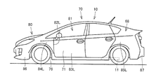
- FIG. 2 is a side view showing a left side surface of electric vehicle 10.
- FIG. 2 is a bottom view of the electric vehicle 10.
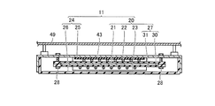
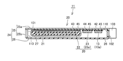
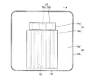
- FIG. 2 is a cross-sectional view showing a power receiving device 11.
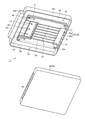
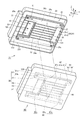
- FIG. 2 is an exploded perspective view of a power receiving device 11.
- FIG. 3 is an exploded perspective view schematically showing a fixing member 27 and a ferrite core 21.
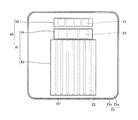
- FIG. 2 is a cross-sectional plan view of the power receiving device 11.
- FIG. FIG. 8 is a cross-sectional view taken along line VIII-VIII in FIG. 4 is a plan view showing a shield 25 and an insulating member 40.
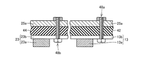
- FIG. 3 is a cross-sectional view showing a configuration around a rectifier 13 and a capacitor 23.
- FIG. It is sectional drawing which shows the modification of fixed aspects, such as the insulating member. It is sectional drawing which shows the element 23a shown by FIG. 11, and the structure of the circumference
- 6 is a graph showing the relationship between the power transmission efficiency when the air gap AG is changed and the frequency f3 of the current supplied to the first coil 58 with the natural frequency f0 fixed. It is the graph which showed the relationship between the distance from an electric current source or a magnetic current source, and the intensity
- 14 is a graph showing the relationship between the amount of lateral deviation between the power reception unit 20 and the power transmission unit 56 and the power transmission efficiency in FIG. 13. It is a graph which shows the relationship between the positional offset amount between the power receiving part 20 and the power transmission part 56 as a comparative example, and electric power transmission efficiency.
- FIG. 6 is a cross-sectional view illustrating a modified example of the power receiving device 11.
- FIG. It is sectional drawing which shows the structure located in the power receiving apparatus 11 and its periphery.
- 2 is a perspective view schematically showing a configuration of a power receiving device 11 and its surroundings.
- FIG. It is a perspective view which shows the power transmission apparatus 50 and the surrounding structure.
- FIG. 10 is a cross-sectional view illustrating a second modification of power reception device 11.
- FIG. 9 is a cross-sectional view illustrating a third modification of power reception device 11.
- FIG. 1 is a schematic diagram schematically showing a power reception device, a power transmission device, and a power transmission system according to the present embodiment.
- the power transmission system includes the electric vehicle 10 including the power receiving device 11 and the external power feeding device 51 including the power transmission device 50.
- the power receiving device 11 of the electric vehicle 10 stops at a predetermined position of the parking space 52 in which the power transmission device 50 is provided, and mainly receives power from the power transmission device 50.
- the parking space 52 is provided with a line indicating a stop, a parking position, and a parking range so that the electric vehicle 10 stops at a predetermined position.
- the external power supply device 51 includes a high-frequency power driver 54 connected to the AC power source 53, a control unit 55 that controls driving of the high-frequency power driver 54 and the like, and a power transmission device 50 connected to the high-frequency power driver 54.
- the power transmission device 50 includes a power transmission unit 56, and the power transmission unit 56 includes a ferrite core 57, a first coil 58 wound around the ferrite core 57, and a capacitor 59 connected to the first coil 58.
- the capacitor 59 is not an essential configuration.
- the first coil 58 is connected to the high frequency power driver 54.
- the power transmission unit 56 includes an electric circuit formed by the inductance of the first coil 58, the stray capacitance of the first coil 58, and the capacitance of the capacitor 59.
- an electric vehicle 10 includes a power receiving device 11, a rectifier 13 connected to the power receiving device 11, a DC / DC converter 14 connected to the rectifier 13, and a battery connected to the DC / DC converter 14. 15, a power control unit (PCU (Power Control Unit)) 16, a motor unit 17 connected to the power control unit 16, a vehicle ECU that controls driving of the DC / DC converter 14, the power control unit 16, and the like ( Electronic Control Unit) 12.
- Electric vehicle 10 according to the present embodiment is a hybrid vehicle including an engine (not shown), but includes a fuel cell vehicle as long as the vehicle is driven by a motor.
- the rectifier 13 is connected to the power receiving device 11, converts an alternating current supplied from the power receiving device 11 into a direct current, and supplies the direct current to the DC / DC converter 14.
- the DC / DC converter 14 adjusts the voltage of the direct current supplied from the rectifier 13 and supplies it to the battery 15.
- the DC / DC converter 14 is not an essential component and may be omitted. In this case, the DC / DC converter 14 can be substituted by providing a matching unit for matching impedance with the external power feeding device 51 between the power transmission device 50 and the high frequency power driver 54.
- the power control unit 16 includes a converter connected to the battery 15 and an inverter connected to the converter, and the converter adjusts (boosts) the direct current supplied from the battery 15 and supplies the DC current to the inverter.
- the inverter converts the direct current supplied from the converter into an alternating current and supplies it to the motor unit 17.
- the motor unit 17 employs, for example, a three-phase AC motor and is driven by an AC current supplied from an inverter of the power control unit 16.
- the electric vehicle 10 further includes an engine or a fuel cell.
- the motor unit 17 includes a motor generator that mainly functions as a generator and a motor generator that mainly functions as an electric motor.
- the power receiving device 11 includes a power receiving unit 20.
- the power receiving unit 20 includes a ferrite core 21, a second coil 22 wound around the outer peripheral surface of the ferrite core 21, and a capacitor 23 connected to the second coil 22.
- the capacitor 23 is not an essential component.
- the second coil 22 is connected to the rectifier 13.
- the second coil 22 has a stray capacitance.
- the power reception unit 20 has an electric circuit formed by the inductance of the second coil 22 and the capacitances of the second coil 22 and the capacitor 23.
- the capacitor 23 is not an essential configuration and can be omitted.
- FIG. 2 is a side view showing the left side surface of the electric vehicle 10.
- FIG. 3 is a bottom view of the electric vehicle 10.
- the electric vehicle 10 includes a vehicle main body 70 and wheels provided on the vehicle main body 70.
- a drive chamber 80 in which the motor unit 17, the engine, and the like are stored
- a passenger storage chamber 81 that is disposed behind the drive chamber 80 in the traveling direction of the electric vehicle 10, and in which passengers can get on and off
- a luggage compartment 68 is formed on the rear side in the traveling direction with respect to the passenger compartment 81.
- a passenger opening / closing opening 82 ⁇ / b> L communicating with the passenger accommodation chamber 81 is formed on the left side surface 71 of the electric vehicle 10.
- the vehicle main body 70 is disposed at a door 83L for opening and closing the entrance opening 82L, a front fender 84L disposed on the front side in the advancing direction with respect to the entrance opening 82L, and disposed on the front side in the advancing direction with respect to the front fender 84.
- the vehicle body 70 includes a rear fender 85L disposed on the rear side in the traveling direction from the opening 82L for getting on and off, and a rear bumper 87 disposed on the rear side in the traveling direction from the rear fender 85L.
- the bottom surface 76 of the electric vehicle 10 means that when the electric vehicle 10 is viewed from a position that is vertically downward with respect to the electric vehicle 10 in a state where the tire of the electric vehicle 10 is in contact with the ground. It is a visible surface.
- electrically powered vehicle 10 includes front wheels 18R and front wheels 18L arranged in the width direction of the vehicle, and rear wheels 19R and rear wheels 19L arranged in the width direction of the vehicle.
- the front wheels 18R and 18L are disposed on the vehicle front side with respect to the rear wheels 19R and 19L.
- the power receiving unit 20 is disposed between the rear wheels 19R and 19L.
- the electric vehicle 10 includes a floor panel 49 that divides the interior of the vehicle from the exterior of the vehicle, a side member 47 that is disposed on the lower surface of the floor panel 49, and a cross member that is disposed on the lower surface of the floor panel 49.
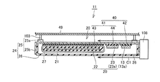
- FIG. 4 is a cross-sectional view showing the power receiving device 11, and FIG. 5 is an exploded perspective view of the power receiving device 11.
- the power receiving device 11 includes a power receiving unit 20, a connection rectifier 13 in the power receiving unit 20, a housing 24 that houses the power receiving unit 20 and the rectifier 13, and a cooling device 108. .
- the housing 24 includes a shield 25 formed so as to open downward, and a lid portion 26 provided so as to close the opening of the shield 25.
- a storage chamber for storing the power reception unit 20 and the rectifier 13 is formed.
- the shield 25 includes a top plate portion 25a and a peripheral wall portion 25b formed so as to hang downward from the peripheral edge portion of the top plate portion 25a.
- the peripheral wall portion 25b includes a plurality of wall portions 25c to 25f, and the plurality of wall portions 25c to 25f are connected to each other to form an annular peripheral wall portion 25b.
- the wall portion 25c and the wall portion 25e are arranged in a direction in which the winding axis O1 of the second coil 22 extends, and the wall portion 25d and the wall portion 25f are arranged in a direction perpendicular to the winding axis O1 of the second coil 22. ing.
- the shape of the shield 25 is not limited to such a shape, and various shapes such as a polygonal shape, a circular liquid, and an oval shape can be employed.
- An opening is formed by the lower end of the peripheral wall 25b, and the lid 26 closes the opening.
- the cooling device 108 is provided on the outer peripheral surface of the wall portion 25e.
- the cooling device 108 supplies cooling air C ⁇ b> 1 as a refrigerant into the housing 24.
- the wall 25e is formed with an opening through which the cooling air C1 enters, and the lid 26 is also formed with an opening 102 through which the cooling air C1 enters.
- An opening 101 through which the cooling air C1 flows is formed in the peripheral wall portion 25c of the shield 25, and an opening through which the cooling air C1 flows is also formed in the lid portion 26.
- the power reception unit 20 includes a ferrite core 21 formed in a plate shape, a fixing member 27 that sandwiches the ferrite core 21 from above and below, a second coil 22 wound around the fixing member 27, and the second coil 22. And a capacitor 23 connected to.
- FIG. 6 is an exploded perspective view schematically showing the fixing member 27 and the ferrite core 21.
- the ferrite core 21 is disposed in the fixing member 27.
- FIG. 7 is a plan sectional view of the power receiving device 11. As shown in FIGS. 6 and 7, the ferrite core 21 is accommodated in the fixing member 27.
- Ferrite core 21 is formed in a plate shape, and includes a lower surface as a first main surface and an upper surface as a second main surface.
- the ferrite core 21 includes a shaft portion 33 around which the second coil 22 is wound, a magnetic pole portion 34 a formed at one end portion of the shaft portion 33, and a magnetic pole formed at the other end portion of the shaft portion 33. Part 34b.
- the width W1 is the width W1
- the width of the magnetic pole portion 34a and the magnetic pole portion 34b in the direction perpendicular to the winding axis O1 is the width W2
- the width W2 is , Larger than the width W1.
- the magnetic pole part 34a includes an extension part 35a formed so as to extend from the end part of the shaft part 33 in the extending direction of the winding axis O1, a protrusion part 35b protruding from one end of the extension part 35a, and an extension part. And a projecting portion 35c formed so as to project from the other end of 35a.
- the width of the extending portion 35a in the direction perpendicular to the winding axis O1 is the same as the width W1 of the shaft portion 33.
- the protruding portion 35b protrudes from the extending portion 35a in a direction intersecting with the winding axis O1.
- the protruding portion 35b protrudes from the end of the extending portion 35a in a direction perpendicular to the winding axis O1.
- the protruding portion 35c is formed on the opposite side of the protruding portion 35b with respect to the extending portion 35a, and protrudes in the direction intersecting the winding axis O1 from the extending portion 35a.
- the length which the protrusion part 35b protrudes from the axial part 33 (extension part 35a) be length L1. Further, when the length that the protruding portion 35c protrudes from the shaft portion 33 (extending portion 35a) is defined as a length L2, the length L1 is larger than the length L2.
- the magnetic pole part 34b is formed similarly to the magnetic pole part 34a.
- the magnetic pole portion 34b includes an extension portion 36a formed so as to extend from the end portion of the shaft portion 33 in a direction extending to the winding axis O1, a protrusion portion 36b protruding from one end of the extension portion 36a, and an extension portion And a protruding portion 36c protruding from the other end of the portion 36a.
- the width of the extending portion 36a in the direction perpendicular to the winding axis O1 is the same as the width W1 of the shaft portion 33.
- the protruding portion 36b protrudes from the extending portion 36a in a direction intersecting with the winding axis O1. In the example shown in FIG. 7, the protrusion 36b protrudes in a direction orthogonal to the winding axis O1.
- the protruding portion 36c protrudes from the end portion of the extending portion 36a in a direction orthogonal to the winding axis O1.
- the length that the protruding portion 36b protrudes from the shaft portion 33 (extending portion 36a) is longer than the length that the protruding portion 36c protrudes from the shaft portion 33 (extending portion 36a).
- the protruding portion 35b and the protruding portion 36b are opposed to each other in the extending direction of the winding axis O1, and the protruding portion 35c and the protruding portion 36c are spaced from each other in the extending direction of the winding axis O1. Facing each other.
- a central portion of the shaft portion 33 in the direction orthogonal to the winding axis O1 is defined as a central portion P1.
- the central part of the magnetic pole part 34a in the direction orthogonal to the winding axis O1 is defined as a central part P2
- the central part of the magnetic pole part 34b in the direction orthogonal to the winding axis O1 is defined as a central part P3.
- the central portion P2 and the central portion P3 are located on one side in the direction orthogonal to the winding axis O1 with respect to the central portion P1. In the present embodiment, the central portion P2 and the central portion P3 are located closer to the cooling device 108 than the central portion P1.
- the insulating piece 30 is disposed on the upper surface of the ferrite core 21 and the insulating piece 31 is disposed on the lower surface of the ferrite core 21. As shown in FIGS.
- the insulating piece 31 is integrated with a fixing member 28 such as a bolt and fixed to the top plate portion 25a of the shield 25.
- the fixing member 27 includes a width detail 37 that covers the shaft portion 33 of the ferrite core 21, a wide portion 38 a that is formed at one end of the width detail 37 and covers the magnetic pole portion 34 a, and a width detail. 37 and a wide portion 38b formed to cover the magnetic pole portion 34b.
- the width detail 37 is formed in a plate shape like the shaft portion 33.
- the recessed part 39 is formed of the width detail 37, the wide part 38a, and the wide part 38b.
- the second coil 22 is wound around the ferrite core 21 with the fixing member 27 interposed therebetween, and the second coil 22 is formed by winding a coil wire so as to surround the winding axis O1. .
- the second coil 22 is formed so as to be displaced in the direction in which the winding axis O1 extends as it goes from one end to the other end.
- the second coil 22 is wound around the outer peripheral surface of the width detail 37. A portion of the second coil 22 located on the lower surface side of the width detail 37 extends in a direction intersecting with the direction in which the winding axis O1 extends.
- the rectifier 13 and the capacitor 23 are disposed in the recess 39. Thereby, the dead space is reduced and the power receiving unit 20 is reduced in size. Electric devices such as the rectifier 13 and the capacitor 23 are provided at a position closer to the cooling device 108 than the second coil 22. Specifically, the capacitor 23 is disposed closer to the cooling device 108 than the second coil 22. The rectifier 13 is disposed closer to the cooling device 108 than the capacitor 23.
- the rectifier 13 includes a substrate 13b and a plurality of elements 13a mounted on the substrate 13b.
- the element 13a is an electronic element such as a diode, for example.
- the capacitor 23 also includes a substrate 23b and a plurality of elements 23a mounted on the substrate 23b.
- the element 23a is, for example, a ceramic capacitor.
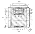
- FIG. 8 is a cross-sectional view taken along the line VIII-VIII in FIG. 7, and FIG. 9 is a plan view showing the shield 25 and the insulating member 40.
- the power receiving device 11 includes an insulating member 40 provided directly on the inner surface of the top plate portion 25a.
- the insulating member 40 includes a power receiving unit insulating member 41 provided between the power receiving unit 20 and the inner surface of the shield 25, and a device insulating member 42 provided between the rectifier 13 and the inner surface of the shield 25. including.
- the power receiving unit insulating member 41 is provided between the second coil 22 and the capacitor 23 and the shield 25 to ensure electrical insulation between the second coil 22 and the shield 25.
- the power receiving unit insulating member 41 includes a coil insulating member 43 and a capacitor insulating member 44.
- the coil insulating member 43 is disposed between the second coil 22 and the shield 25, and the capacitor insulating member 44 is disposed between the capacitor 23 and the shield 25.
- the coil insulating member 43 and the capacitor insulating member 44 are provided directly on the top plate portion 25a.
- the coil insulating member 43 ensures electrical insulation between the second coil 22 and the shield 25, and the capacitor insulating member 44 ensures electrical insulation between the capacitor 23 and the shield 25.
- the device insulation member 42 is also provided directly on the top plate portion 25a, and the device insulation member 42a ensures electrical insulation between the rectifier 13 and the top plate portion 25a.
- the device insulating member 42, the coil insulating member 43, and the capacitor insulating member 44 are all formed in a plate shape.
- FIG. 10 is a cross-sectional view showing a configuration around the rectifier 13 and the capacitor 23.
- capacitor 23 includes a substrate 23b and an element 23a mounted on the main surface of substrate 23b.
- Rectifier 13 includes a substrate 13b and an element 13a mounted on the main surface of substrate 13b.
- the capacitor insulating member 44 and the capacitor 23 are fixed to the top plate portion 25a by a fixing member 48b such as a bolt.
- the rectifier 13 and the capacitor insulating member 44 are fixed to the top plate portion 25a by a fixing member 48a.
- the capacitor 23 and the rectifier 13 are fixed to the shield with the insulating member interposed therebetween.
- the rectifier 13 is in surface contact with the top plate portion 25a with the device insulating member 42 interposed therebetween, and the capacitor 23 is fixed to the top plate portion 25a with the capacitor insulating member 44 interposed therebetween. ing.
- the second coil 22 is wound around the peripheral surface of the fixing member 27, and the second coil 22 is pressed against the coil insulating member 43 by the fixing member 28.
- the fixing member 27 around which the second coil 22 is wound is fixed to the shield 25 by the fixing member 28.
- the second coil 22 is in surface contact with the inner surface of the shield 25 with the coil insulating member 43 interposed therebetween.
- FIG. 11 is a cross-sectional view showing a modification of the fixing mode of the insulating member 40 and the like.
- the heat conductive member 45 is arrange
- FIG. 12 is a cross-sectional view showing the element 23a shown in FIG. 11 and the surrounding configuration. As shown in FIG. 12, a heat conductive member 45 is disposed between the capacitor insulating member 44 and the top plate portion 25a.
- the heat conductive member 45 is made of, for example, an insulating low-hardness material and has viscosity. As the heat conductive member 45, for example, heat conductive low hardness acrylic or the like can be employed. The heat conductive member 45 bonds the capacitor insulating member 44 and the top plate portion 25a.
- the heat conductive member 45 is an example of a member disposed between the insulating member 40 and the top plate portion 25a, and other insulating material or conductive material may be disposed.
- the power receiving device 11 formed in this way is provided on the bottom surface 76 side of the electric vehicle 10 as shown in FIG.
- Various methods can be adopted as a method of fixing the power receiving device 11.
- the power receiving device 11 may be suspended from the side member 47 or the cross member.
- the electric device 11 may be fixed to the floor panel 49.
- an under cover may be disposed on the lower surface side of the power receiving device 11.
- “disposing the power receiving device 11 on the bottom surface 76 side” does not necessarily have to be provided at a position where the power receiving device 11 can be seen when the electric vehicle 10 is viewed from below the electric vehicle 10. . For this reason, for example, the power receiving device 11 is disposed below the floor panel 49.
- FIG. 13 is a perspective view showing a state in which the power reception unit 20 and the power transmission unit 56 are arranged to face each other.
- the lid portion 26 provided in the power receiving device 11 is not illustrated.
- the power receiving unit 20 and the power transmitting unit 56 are arranged to face each other with an air gap therebetween.
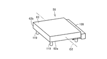
- the power transmission device 50 includes a power transmission unit 56, a housing 60 that houses the power transmission unit 56 therein, and a cooling device 105.
- the housing 60 includes a shield 62 formed of a metal material such as copper, and a resin lid member 63 provided on the shield 62.
- FIG. 14 is a cross-sectional view of the power transmission device 50 shown in FIG.
- the shield 62 includes a bottom surface portion 62a and a peripheral wall portion 62b formed in an annular shape so as to rise upward from the outer peripheral edge portion of the bottom surface portion 62a.
- An opening that opens upward is formed by the annular upper end of the peripheral wall 62b.
- the peripheral wall part 62b includes a wall part in which the opening part 114 is formed and a wall part in which the plurality of opening parts 116 are formed.
- the capacitor 59 and the second coil 22 are located between the two portions.
- the lid member 63 is formed so as to close the opening formed by the upper end portion of the peripheral wall portion of the shield 62.
- the lid member 63 is formed with an opening 115 that communicates with the opening 114 and an opening 117 that communicates with the opening 116.
- the cooling device 105 is provided on the outer peripheral surface of the peripheral wall 62b in which the opening 114 is formed.
- the cooling air C ⁇ b> 2 from the cooling device 105 passes through the openings 114 and 115, enters the housing 60, passes through the openings 116 and 117, and is exhausted to the outside of the housing 60.
- the power transmission unit 56 includes a fixing member 61 housed in the housing 60, a ferrite core 57 housed in the fixing member 61, a first coil 58 mounted on the outer peripheral surface of the fixing member 61, and the housing 60. And a capacitor 59 housed therein.
- the first coil 58 is wound around the fixing member 61.
- the capacitor 59 is disposed closer to the cooling device 105 than the first coil 58.
- the ferrite core 57 is accommodated in the fixing member 61.
- the fixing member 61 includes an insulating piece 61 a arranged on the upper surface side of the ferrite core 57 and an insulating piece 61 b arranged on the lower surface side of the ferrite core 57.
- the first coil 58 is formed so as to surround the winding axis O2, and is formed so as to be displaced in the extending direction of the winding axis O2 from one end to the other end.
- the ferrite core 57 is formed in a plate shape.
- the ferrite core 57 includes a shaft portion 65 around which the first coil 58 is wound, a magnetic pole portion 66 formed at one end of the shaft portion 65, and a magnetic pole portion 67 formed at the other end of the shaft portion 65. .
- the width of the shaft portion 65 in the direction perpendicular to the winding axis O2 is smaller than the width of the magnetic pole portion 67 in the direction perpendicular to the winding axis O2 and the width of the magnetic pole portion 66 in the direction perpendicular to the winding axis O2.
- the magnetic pole portion 67 is continuously extended from the shaft portion 65 and protrudes in a direction in which the winding axis O2 extends, and a direction intersecting the winding axis O2 from one end portion of the extension portion 67a (for example, vertical) Projecting portion 67b projecting in the direction) and a projecting portion 67c projecting in the direction intersecting with the winding axis O2 (for example, a perpendicular direction) from the other end of the extending portion 67a.
- the protruding portion 66b and the protruding portion 67b face each other in the extending direction of the winding axis O2, and the protruding portion 66c and the protruding portion 67c face each other in the extending direction of the winding axis O2.
- the width of the extending portion 67a in the direction perpendicular to the winding axis O2 is substantially the same as the width of the shaft portion 65 in the direction perpendicular to the winding axis O2.
- the protruding length of the protruding portion 67b protruding from the extending portion 67a or the shaft portion 65 is longer than the protruding length of the protruding portion 67c protruding from the extending portion 67a or the shaft portion 65.
- the width of the extending portion 66a in the direction perpendicular to the winding axis O2 is substantially the same as the width of the shaft portion 65 in the direction perpendicular to the winding axis O2.
- the protruding length of the protruding portion 66b protruding from the extending portion 66a or the shaft portion 65 is longer than the protruding length of the protruding portion 66c protruding from the extending portion 66a or the shaft portion 65.
- a central portion of the shaft portion 33 in the direction orthogonal to the winding axis O2 is defined as a central portion P4.
- the central portion of the magnetic pole portion 67 in the direction orthogonal to the winding axis O2 is defined as a central portion P5
- the central portion of the magnetic pole portion 66 in the direction orthogonal to the winding axis O2 is defined as a central portion P6.
- the central portion P5 and the central portion P6 are located on one side in the direction orthogonal to the winding axis O2 with respect to the central portion P4. In the present embodiment, the central part P5 and the central part P6 are located closer to the cooling device 105 than the central part P4.
- the fixing member 61 includes an insulating piece 61 a disposed on the upper surface of the ferrite core 57 and an insulating piece 61 b disposed on the lower surface of the ferrite core 57.
- the ferrite core 57 is protected by sandwiching the ferrite core 57 between the insulating piece 61a and the insulating piece 61b.
- the fixing member 61 includes a width detail 69a that covers the shaft portion 65, a wide portion 69b that covers the magnetic pole portion 67, and a wide portion 69c that covers the magnetic pole portion 66.
- the wide portion 69b is formed at one end of the width detail 69a and protrudes in a direction intersecting the winding axis O2.
- the wide portion 69c is formed at the other end and protrudes in a direction intersecting with the winding axis O2.
- the recessed part 73 is formed of the detail 69a, the wide part 69b, and the wide part 69c.
- the capacitor 59 is disposed in the recess 73, and effective use of dead space is achieved. Thereby, size reduction of the power transmission apparatus 50 is achieved.
- the capacitor 59 includes a substrate 59b fixed to the bottom surface portion 62a and an element 59a mounted on the main surface of the substrate 59b.
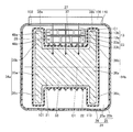
- FIG. 15 is a plan view showing the shield 62 in a state where devices such as the power receiving unit 20 are removed.
- the insulating member 74 includes an insulating member 74a and an insulating member 74b, and the insulating member 74a ensures insulation between the capacitor 59 and the bottom surface portion 62a.
- the insulating member 74b ensures insulation between the first coil 58 and the bottom surface portion 62a.
- the power transmission unit 56 is fixed to the bottom surface part 62a by a fixing member such as a bolt.
- the first coil 58 is pressed against the insulating member 74b by fixing the power transmission unit 56 to the bottom surface 62a. Therefore, the capacitor 59 is in surface contact with the bottom surface portion 62a with the insulating member 74a interposed therebetween.
- the first coil 58 is in surface contact with the bottom surface portion 62a with the insulating member 74b interposed therebetween.
- the difference between the natural frequency of power transmission unit 56 and the natural frequency of power reception unit 20 is 10% or less of the natural frequency of power reception unit 20 or power transmission unit 56. is there.
- the power transmission efficiency can be increased.
- the difference between the natural frequencies becomes larger than 10% of the natural frequency of the power receiving unit 20 or the power transmitting unit 56, the power transmission efficiency becomes smaller than 10%, and the adverse effects such as the charging time of the battery 15 become longer. .
- the natural frequency of the power transmission unit 56 is the case where the electric circuit formed by the inductance of the first coil 58 and the capacitance of the first coil 58 freely vibrates when the capacitor 59 is not provided.
- the natural frequency of the power transmission unit 56 is vibration when the electric circuit formed by the capacitance of the first coil 58 and the capacitor 59 and the inductance of the first coil 58 freely vibrates.
- Means frequency In the above electric circuit, the natural frequency when the braking force and the electric resistance are zero or substantially zero is also referred to as a resonance frequency of the power transmission unit 56.
- the natural frequency of the power receiving unit 20 is the case where the electric circuit formed by the inductance of the second coil 22 and the capacitance of the second coil 22 freely vibrates when the capacitor 23 is not provided.
- the natural frequency of the power reception unit 20 is vibration when the electric circuit formed by the capacitance of the second coil 22 and the capacitor 23 and the inductance of the second coil 22 freely vibrates.
- the natural frequency when the braking force and the electric resistance are zero or substantially zero is also referred to as a resonance frequency of the power receiving unit 20.
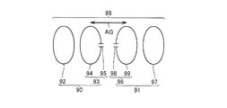
- FIG. 16 shows a simulation model of the power transmission system.
- the power transmission system includes a power transmission device 90 and a power reception device 91, and the power transmission device 90 includes a coil 92 (electromagnetic induction coil) and a power transmission unit 93.
- the power transmission unit 93 includes a coil 94 (resonance coil) and a capacitor 95 provided in the coil 94.
- the power receiving device 91 includes a power receiving unit 96 and a coil 97 (electromagnetic induction coil).
- the power reception unit 96 includes a coil 99 and a capacitor 98 connected to the coil 99 (resonance coil).
- the inductance of the coil 94 is an inductance Lt
- the capacitance of the capacitor 95 is a capacitance C1.
- the inductance of the coil 99 is defined as inductance Lr
- the capacitance of the capacitor 98 is defined as capacitance C2.
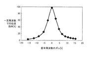
- the horizontal axis indicates the deviation (%) of the natural frequency
- the vertical axis indicates the transmission efficiency (%) at a constant frequency.
- the deviation (%) in the natural frequency is expressed by the following equation (3).
- the power transmission efficiency can be increased. Furthermore, the power transmission efficiency can be further improved by setting the natural frequency of each power transmission unit and the power receiving unit so that the absolute value of the deviation (%) of the natural frequency is 5% or less of the natural frequency of the power receiving unit 96. I understand that I can do it.
- simulation software electromagnetic field analysis software (JMAG (registered trademark): manufactured by JSOL Corporation) is employed.
- the first coil 58 is supplied with AC power from the high frequency power driver 54. At this time, electric power is supplied so that the frequency of the alternating current flowing through the first coil 58 becomes a specific frequency.
- the second coil 22 is disposed within a predetermined range from the first coil 58, and the second coil 22 receives electric power from an electromagnetic field formed around the first coil 58.
- so-called helical coils are used for the second coil 22 and the first coil 58. For this reason, a magnetic field and an electric field that vibrate at a specific frequency are formed around the first coil 58, and the second coil 22 mainly receives electric power from the magnetic field.
- the “magnetic field of a specific frequency” typically has a relationship with the power transmission efficiency and the frequency of the current supplied to the first coil 58.
- the power transmission efficiency when power is transmitted from the first coil 58 to the second coil 22 varies depending on various factors such as the distance between the first coil 58 and the second coil 22.
- the natural frequency (resonance frequency) of the power transmission unit 56 and the power reception unit 20 is the natural frequency f0
- the frequency of the current supplied to the first coil 58 is the frequency f3
- the frequency between the second coil 22 and the first coil 58 is Let the air gap be the air gap AG.
- FIG. 18 is a graph showing the relationship between the power transmission efficiency when the air gap AG is changed and the frequency f3 of the current supplied to the first coil 58 with the natural frequency f0 fixed.
- the horizontal axis indicates the frequency f3 of the current supplied to the first coil 58
- the vertical axis indicates the power transmission efficiency (%).
- the efficiency curve L1 schematically shows the relationship between the power transmission efficiency when the air gap AG is small and the frequency f3 of the current supplied to the first coil 58. As shown in the efficiency curve L1, when the air gap AG is small, the peak of power transmission efficiency occurs at frequencies f4 and f5 (f4 ⁇ f5). When the air gap AG is increased, the two peaks when the power transmission efficiency is increased change so as to approach each other.
- the peak of the power transmission efficiency is one, and the power transmission efficiency is obtained when the frequency of the current supplied to the first coil 58 is the frequency f6. Becomes a peak.
- the peak of power transmission efficiency is reduced as shown by the efficiency curve L3.
- the following first method can be considered as a method for improving the power transmission efficiency.
- the frequency of the current supplied to the first coil 58 shown in FIG. 1 is constant, and the capacitances of the capacitor 59 and the capacitor 23 are changed according to the air gap AG.
- a method of changing the characteristic of the power transmission efficiency with the unit 20 can be mentioned. Specifically, the capacitances of the capacitor 59 and the capacitor 23 are adjusted so that the power transmission efficiency reaches a peak in a state where the frequency of the current supplied to the first coil 58 is constant. In this method, the frequency of the current flowing through the first coil 58 and the second coil 22 is constant regardless of the size of the air gap AG.
- a method for changing the characteristics of the power transmission efficiency a method using a matching device provided between the power transmission device 50 and the high-frequency power driver 54, a method using the converter 14, or the like can be adopted. .
- the second method is a method of adjusting the frequency of the current supplied to the first coil 58 based on the size of the air gap AG.
- the power transmission characteristic is the efficiency curve L ⁇ b> 1
- a current having a frequency f ⁇ b> 4 or a frequency f ⁇ b> 5 is supplied to the first coil 58.
- the frequency characteristic becomes the efficiency curves L 2 and L 3
- a current having a frequency f 6 is supplied to the first coil 58.
- the frequency of the current flowing through the first coil 58 and the second coil 22 is changed in accordance with the size of the air gap AG.
- the frequency of the current flowing through the first coil 58 is a fixed constant frequency
- the frequency flowing through the first coil 58 is a frequency that changes as appropriate according to the air gap AG.
- the first coil 58 is supplied with a current having a specific frequency set so as to increase the power transmission efficiency by the first method, the second method, or the like.
- a current having a specific frequency flows through the first coil 58
- a magnetic field electromagnettic field
- the power reception unit 20 receives power from the power transmission unit 56 through a magnetic field that is formed between the power reception unit 20 and the power transmission unit 56 and vibrates at a specific frequency.
- the “magnetic field oscillating at a specific frequency” is not necessarily a magnetic field having a fixed frequency.
- the frequency of the current supplied to the first coil 58 is set, but the power transmission efficiency is the horizontal of the first coil 58 and the second coil 22. It varies depending on other factors such as a shift in direction, and the frequency of the current supplied to the first coil 58 may be adjusted based on the other factors.
- FIG. 19 is a diagram showing the relationship between the distance from the current source or the magnetic current source and the strength of the electromagnetic field.
- the electromagnetic field is composed of three components.
- the curve k1 is a component that is inversely proportional to the distance from the wave source, and is referred to as a “radiated electromagnetic field”.
- a curve k2 is a component inversely proportional to the square of the distance from the wave source, and is referred to as an “induction electromagnetic field”.
- the curve k3 is a component inversely proportional to the cube of the distance from the wave source, and is referred to as an “electrostatic magnetic field”.
- the wavelength of the electromagnetic field is “ ⁇ ”
- the distance at which the strengths of the “radiant electromagnetic field”, the “induction electromagnetic field”, and the “electrostatic magnetic field” are approximately equal can be expressed as ⁇ / 2 ⁇ .
- the “electrostatic magnetic field” is a region where the intensity of electromagnetic waves suddenly decreases with the distance from the wave source.
- this “electrostatic magnetic field” is a dominant near field (evanescent field). ) Is used to transmit energy (electric power). That is, in the near field where the “electrostatic magnetic field” is dominant, by resonating the power transmitting unit 56 and the power receiving unit 20 (for example, a pair of LC resonance coils) having adjacent natural frequencies, the power receiving unit 56 and the other power receiving unit are resonated. Energy (electric power) is transmitted to 20. Since this "electrostatic magnetic field” does not propagate energy far away, the resonance method transmits power with less energy loss than electromagnetic waves that transmit energy (electric power) by "radiant electromagnetic field” that propagates energy far away. be able to.
- the power transmission unit and the power reception unit are referred to as a near-field resonance (resonance) coupling field, for example.
- a near-field resonance (resonance) coupling field for example.
- coupling coefficient (kappa) between a power transmission part and a power receiving part is about 0.3 or less, for example, Preferably, it is 0.1 or less.
- a coupling coefficient ⁇ in the range of about 0.1 to 0.3 can also be employed.
- the coupling coefficient ⁇ is not limited to such a value, and may take various values that improve power transmission.
- magnetic resonance coupling For example, “magnetic resonance coupling”, “magnetic field (magnetic field) resonance coupling”, “magnetic field resonance (resonance) coupling”, “near-field resonance” may be used as the coupling between the power transmitting unit 56 and the power receiving unit 20 in the power transmission of the present embodiment.
- (Resonant) coupling "
- Electromagnetic field (electromagnetic field) resonant coupling "or” Electric field (electric field) resonant coupling ".
- Electromagnetic field (electromagnetic field) resonance coupling means a coupling including any of “magnetic resonance coupling”, “magnetic field (magnetic field) resonance coupling”, and “electric field (electric field) resonance coupling”.
- the power transmission unit 56 and the power reception unit 20 are mainly used.
- the power transmission unit 56 and the power reception unit 20 are “magnetic resonance coupled” or “magnetic field (magnetic field) resonance coupled”.
- an antenna such as a meander line may be employed as the first coils 58 and 22, and in this case, the power transmission unit 56 and the power reception unit 20 are mainly coupled by an electric field. At this time, the power transmission unit 56 and the power reception unit 20 are “electric field (electric field) resonance coupled”.
- the magnetic path passes through the magnetic pole part 66, the shaft part 65, the magnetic pole part 67, the air gap, the magnetic pole part 34b, the shaft part 33, the magnetic pole part 34a, and the air gap.
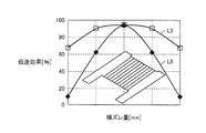
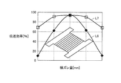
- FIG. 20 is a graph showing the relationship between the amount of lateral deviation between the power reception unit 20 and the power transmission unit 56 in FIG. 13 and the power transmission efficiency.
- the direction in which the winding axis O1 extends is the Y-axis direction.
- the direction perpendicular to the winding axis O1 is taken as the X-axis direction.
- a direction in which the power reception unit 20 and the power transmission unit 56 are separated from each other in the vertical direction is defined as a Z-axis direction.
- Curve L5 shows the relationship between the amount of displacement between the power reception unit 20 and the power transmission unit 56 in the X-axis direction and the power transmission efficiency.
- a curve L6 shows the relationship between the amount of positional deviation between the power reception unit 20 and the power transmission unit 56 in the Y-axis direction and the power transmission efficiency.
- FIG. 21 is a graph showing the relationship between the amount of misalignment between the power reception unit 20 and the power transmission unit 56 as a comparative example, and the power transmission efficiency.
- the ferrite core 21 is formed in an H shape.
- the shaft portion 33 has the magnetic pole portion 34 a and the magnetic pole portion so that the length L 1 from which the protruding portions 35 b and 36 b protrude is equal to the length L 2 from which the protruding portions 35 c and 36 c protrude. 34b.
- the power transmission unit 56 also has an H-shaped ferrite core.
- a curve L7 indicates the relationship between the amount of positional deviation in the X-axis direction and power transmission efficiency. Furthermore, the curve L8 shows the relationship between the amount of displacement in the Y-axis direction and the power transmission efficiency.
- the power transmission characteristics of the power transmission system according to the present embodiment and the power transmission characteristics of the power transmission system according to the comparative example are approximate.
- the second coil 22, the capacitor 23, the rectifier 13 and the like generate heat.
- the second coil 22 is pressed against the coil insulating member 43, and the coil insulating member 43 is in direct contact with the top plate portion 25a.
- the heat of the second coil 22 is mainly dissipated to the shield 25 formed of a metal material such as copper. Thereby, it can suppress that the 2nd coil 22 becomes high temperature.
- the rectifier 13 is also fixed to the device insulating member 42, and the device insulating member 42 is directly fixed to the top plate portion 25a. For this reason, the heat from the rectifier 13 is radiated well to the shield 25.
- the heat conductive member 45 is provided between the heat conductive member 45 and the top plate portion 25a, the heat from the second coil 22 can be satisfactorily applied to the top plate portion 25a. It can dissipate heat.
- the heat conductive member 45 is disposed between the capacitor insulating member 44 and the device insulating member 42 and the top plate portion 25a, the heat of the capacitor 23 and the rectifier 13 can be radiated to the shield 25 satisfactorily. be able to.
- the shield 25 as a heat radiating unit, various devices mounted on the power receiving unit 20 can be cooled well. 14 and 15, also in the power transmission unit 56, the heat from the first coil 58 and the capacitor 59 is well dissipated to the shield 62.
- the cooling air C ⁇ b> 1 from the cooling device 108 enters the housing 24 through the opening 110 formed in the shield 25 and the opening 102 formed in the lid 26.
- the cooling air C ⁇ b> 1 entering the housing 24 is exhausted to the outside through the opening 113 formed in the lid 26 and the opening 112 formed in the shield 25.
- the flow direction of the cooling air C ⁇ b> 1 is a direction from the openings 110 and 102 toward the openings 112 and 113.
- the flow direction of the cooling air C1 is a direction that intersects the winding axis O1.
- the electrical devices such as the rectifier 13 and the capacitor 23 are located upstream of the second coil 22 in the flow direction of the cooling air C1
- the element 13a of the rectifier 13 and the element 23a of the capacitor 23 are cooled well. Can do.
- the rectifier 13 is disposed upstream of the capacitor 23 in the flow direction of the cooling air C1. Thereby, a diode with low heat resistance can be cooled favorably.
- the direction in which the portion of the second coil 22 located on the lower surface of the width detail 37 extends and the flow direction of the cooling air C1 are both directions that intersect the direction in which the winding axis O1 extends. For this reason, the cooling air C ⁇ b> 1 flows along a portion of the second coil 22 located on the lower surface of the width detail 37.
- the cooling air from the cooling device 105 passes through the opening 114 and the opening 115 and enters the housing 60. Then, the capacitor 59 and the first coil 58 are cooled and exhausted to the outside from the opening 117 and the opening 116.
- the flow direction of the cooling air C2 is a direction that intersects the direction in which the winding axis O2 extends, and the capacitor 59 is disposed upstream of the first coil 58 in the flow direction of the cooling air C2.
- the capacitor 59 can be cooled well.
- a portion of the first coil 58 located on the upper surface of the ferrite core 57 extends in a direction intersecting with the winding axis O2, and the cooling air C2 also extends in a direction intersecting with the winding axis O2.
- the cooling air C ⁇ b> 2 flows along a portion of the first coil 58 located on the upper surface of the ferrite core 57. Thereby, the distribution resistance of the cooling air C2 is reduced, and the cooling efficiency of the cooling air C2 is improved.
- FIG. 22 is a cross-sectional view illustrating a modified example of the power receiving device 11.
- the rectifier 13 is disposed at a position adjacent to the second coil 22, and the capacitor 23 is disposed on the opposite side of the rectifier 13 from the second coil 22. For this reason, the rectifier 13 is disposed upstream of the second coil 22 in the flow direction of the cooling air C1.
- the capacitor 23 is disposed upstream of the rectifier 13 in the flow direction of the cooling air C1.
- the capacitance of the element 23a of the capacitor 23 is highly temperature dependent. Therefore, in the example shown in FIG. 22, the capacitor 23 is arranged upstream of the rectifier 13 in the flow direction of the cooling air C ⁇ b> 1, thereby suppressing the fluctuation of the capacitance of the element 23 a.
- FIG. 23 is a cross-sectional view showing the power receiving device 11 and the configuration located around it
- FIG. 24 is a perspective view schematically showing the power receiving device 11 and the surrounding configuration.
- a plurality of suspension portions 103 are provided on the upper surface of the housing 24, and the housing 24 is suspended on the lower surface of the floor panel 49. For this reason, a gap is formed between the upper surface of the housing 24 and the lower surface of the floor panel 49.
- the housing 24 is sealed.
- the cooling device 108 blows cooling air C ⁇ b> 1 on the outer surface of the housing 24.
- the top plate portion 25a of the shield 25 is actively cooled by the cooling air C1.
- the rectifier 13 and the capacitor 23 are attached to the top plate portion 25a, and the rectifier 13, the capacitor 23, and the top plate are mounted. Between the portion 25a, an equipment insulating member 42 and a capacitor insulating member 44 are disposed.
- the second coil 22 is also attached to the top plate portion 25a, and a coil insulating member 43 is provided between the second coil 22 and the top plate portion 25a.
- the rectifier 13, the capacitor 23, and the second coil 22 can be satisfactorily cooled by blowing the cooling air C1 to the top plate portion 25a.
- the rectifier 13 is positioned upstream of the capacitor 23 in the flow direction of the cooling air C1, and the capacitor 23 is cooled more than the second coil 22. It is located upstream in the flow direction of the wind C1.
- the rectifier 13 can be cooled favorably.
- the capacitor 23 may be arranged upstream of the rectifier 13 in the flow direction of the cooling air C1. In this case, the capacitor 23 can be cooled well.
- the casing 24 is hermetically sealed, and foreign substances such as rainwater are prevented from entering from the outside.
- FIG. 25 is a perspective view showing the configuration of the power transmission device 50 and its surroundings
- FIG. 26 is a perspective view showing the configuration of the power transmission device 50 and its surroundings.
- the casing 60 is accommodated in a groove 118 formed on the ground.
- the bottom surface portion 62 a of the shield 62 is supported by a plurality of support pillars 119, and a gap is formed between the bottom surface portion 62 a and the inner surface of the groove portion 118.
- a gap is also formed between the peripheral wall 62 b of the shield 62 and the inner surface of the groove 118. The gaps communicate with each other, and a flow path through which the cooling air C2 flows is formed.
- the cooling air C2 from the cooling device 109 passes between the bottom surface portion 62a and the inner surface of the groove portion 118, and between the peripheral wall portion 62b and the groove portion 118, and is exhausted to the outside.
- the capacitor 59 is attached to the peripheral wall portion 62b, and the insulating member 74a is disposed between the capacitor 59 and the peripheral wall portion 62b.
- the first coil 58 is also attached to the bottom surface portion 62a, and an insulating member 74b is disposed between the first coil 58 and the bottom surface portion 62a.
- the bottom surface portion 62a is cooled, and the capacitor 59 and the first coil 58 can be cooled well.
- the capacitor 59 is disposed upstream of the first coil 58 in the flow direction of the cooling air C2. For this reason, the capacitor 59 can be cooled satisfactorily.
- FIG. 27 is a cross-sectional view illustrating a second modification of the power receiving device 11.
- the ferrite core 21 is formed in an H shape.
- the protruding lengths of the protruding portions 35b and 36b are substantially equal to the protruding lengths of the protruding portions 35c and 36c.
- the rectifier 13 is disposed upstream of the capacitor 23 in the flow direction of the cooling air C1, and the capacitor 23 is upstream of the second coil 22 in the flow direction of the cooling air C1. Arranged on the side.
- FIG. 28 is a cross-sectional view showing a third modification of the power receiving device 11.
- the ferrite core 21 is formed in a circular plate shape, and the second coil 22 is disposed on the lower surface of the plate-shaped ferrite core 21.
- the second coil 22 is not wound around the ferrite core 21.
- the second coil 22 provided in the ferrite core 21 is not limited to the case where the second coil 22 is wound around the peripheral surface of the ferrite core 21, and includes the case where the second coil 22 is disposed around the ferrite core 21. .
- the capacitor 23 is arranged upstream of the second coil 22 in the flow direction of the cooling air C1, and the rectifier 13 is upstream of the capacitor 23 in the flow direction of the cooling air C1. Is arranged.
- the rectifier 13 can be cooled satisfactorily.
- the power receiving device 11 has been described. Needless to say, the H-shaped core and the circular coil can be applied to the power transmitting device 50 as well.
- an electromagnetic induction coil that receives electric power from the second coil 22 by electromagnetic induction may be arranged, and the electromagnetic induction coil may be connected to the rectifier 13.
- an electromagnetic induction coil that transmits electric power by electromagnetic induction may be disposed in the first coil 58, and this electromagnetic induction coil may be connected to the high frequency power driver 54.
- the present invention is suitable for a power receiving device and a power transmitting device.
Landscapes
- Engineering & Computer Science (AREA)
- Power Engineering (AREA)
- Computer Networks & Wireless Communication (AREA)
- Transportation (AREA)
- Mechanical Engineering (AREA)
- Physics & Mathematics (AREA)
- Electromagnetism (AREA)
- Current-Collector Devices For Electrically Propelled Vehicles (AREA)
- Electric Propulsion And Braking For Vehicles (AREA)
- Coils Or Transformers For Communication (AREA)
Abstract
Description
好ましくは、上記第1コイルは、第2巻回軸の周囲を取り囲むように形成される。上記コアは、第1コイルが巻回される第2軸部と、第2軸部の第3端部に形成され、第2巻回軸の延びる方向と交差する第2交差方向に延びる第3磁極部と、第2軸部の第4端部に形成され、第2交差方向に延びる第4磁極部とを含む。上記第2交差方向における第2軸部の幅は、第2交差方向における第3磁極部の長さおよび第4磁極部の長さよりも短い。上記第2交差方向における第3磁極部の中央に位置する第4中央部と、第2交差方向における第4磁極部の中央に位置する第5中央部とは、第2交差方向における第2軸部の中央に位置する第6中央部より第2交差方向の一方側に位置する。上記電気機器は、第2軸部に対して第2交差方向の一方側に配置されると共に、第3磁極部および第4磁極部の間に配置される。
好ましくは、上記第1コイルは、第2巻回軸の周囲を取り囲むように形成される。上記冷却装置は、第2巻回軸の延びる方向と交差する第2交差方向に冷媒を供給する。好ましくは、上記筐体は、密閉される。
f2=1/{2π(Lr×C2)1/2}・・・(2)
ここで、インダクタンスLrおよびキャパシタンスC1,C2を固定して、インダクタンスLtのみを変化させた場合において、送電部93および受電部96の固有周波数のズレと、電力伝送効率との関係を図16に示す。なお、このシミュレーションにおいては、コイル94およびコイル99の相対的な位置関係は固定した状態であって、さらに、送電部93に供給される電流の周波数は一定である。
図17からも明らかなように、固有周波数のズレ(%)が±0%の場合には、電力伝送効率は、100%近くとなる。固有周波数のズレ(%)が±5%の場合には、電力伝送効率は、40%となる。固有周波数のズレ(%)が±10%の場合には、電力伝送効率は、10%となる。固有周波数のズレ(%)が±15%の場合には、電力伝送効率は、5%となる。すなわち、固有周波数のズレ(%)の絶対値(固有周波数の差)が、受電部96の固有周波数の10%以下の範囲となるように各送電部および受電部の固有周波数を設定することで電力伝送効率を高めることができることがわかる。さらに、固有周波数のズレ(%)の絶対値が受電部96の固有周波数の5%以下となるように、各送電部および受電部の固有周波数を設定することで電力伝送効率をより高めることができることがわかる。なお、シミュレーションソフトしては、電磁界解析ソフトウェア(JMAG(登録商標):株式会社JSOL製)を採用している。
図1において、第1コイル58には、高周波電力ドライバ54から交流電力が供給される。この際、第1コイル58を流れる交流電流の周波数が特定の周波数となるように電力が供給されている。
図23および図24を用いて、本実施の形態2に係る受電装置11と送電装置50とについて説明する。なお、図23および図24に示す構成のうち、上記図1から図22に示す構成と同一または相当する構成については、どの説明を省略する場合がある。
Claims (19)
- 第1コイル(58)を含む送電部から非接触で電力を受電する受電装置であって、
内部に収容部が形成された筐体(24)と、
前記筐体(24)内に配置されたコア(21)と、
前記筐体(24)内に配置され、前記コア(21)に設けられた第2コイル(22)と、
前記筐体(24)内に配置されると共に、前記第2コイル(22)に接続された電気機器と、
前記筐体(24)の内表面と前記第2コイル(22)との間と、前記筐体(24)の内表面と前記電気機器との間に配置された絶縁部材(40)と、
冷媒を流通させて、前記第2コイル(22)および前記電気機器を冷却する冷却装置と、
を備え、
前記第2コイル(22)と前記電気機器とは、前記絶縁部材(40)を間に挟んで前記筐体(24)の内表面に取り付けられ、
前記電気機器は前記第2コイル(22)よりも前記冷媒の流通方向の上流に配置された、受電装置。 - 前記電気機器は、前記第2コイル(22)に接続されたキャパシタ(23)と、前記第2コイル(22)が受電した電流を整流する整流器(13)とを含み、
前記整流器(13)は、前記キャパシタ(23)よりも前記冷媒の流通方向の上流側に配置され、
前記キャパシタ(23)は、前記第2コイル(22)よりも前記冷媒の流通方向の上流側に配置された、請求項1に記載の受電装置。 - 前記電気機器は、前記第2コイル(22)に接続されたキャパシタ(23)と、前記第2コイル(22)が受電した電流を整流する整流器(13)とを含み、
前記キャパシタ(23)は、前記整流器(13)よりも前記冷媒の流通方向の上流側に配置され、
前記整流器(13)は、前記第2コイル(22)よりも前記冷媒の流通方向の上流側に配置された、請求項1に記載の受電装置。 - 前記第2コイル(22)は、第1巻回軸(O1)の周囲を取り囲むように形成され、
前記コア(21)は、前記第2コイル(22)が巻回される第1軸部(33)と、前記第1軸部(33)の第1端部に形成され、前記第1巻回軸(O1)の延びる方向と交差する第1交差方向に延びる第1磁極部(34a)と、前記第1軸部(33)の第2端部に形成され、前記第1交差方向に延びる第2磁極部(34b)とを含み、
前記第1交差方向における前記第1軸部(33)の幅は、前記第1交差方向における前記第1磁極部(34a)の長さおよび第2磁極部(34b)の長さよりも短く、
前記第1交差方向における前記第1磁極部(34a)の中央に位置する第1中央部(P1)と、前記第1交差方向における前記第2磁極部(34b)の中央に位置する第2中央部(P2)とは、前記第1交差方向における前記第1軸部(33)の中央に位置する第3中央部より前記第1交差方向の一方側に位置し、
前記電気機器は、前記第1軸部(33)に対して前記第1交差方向の一方側に配置されると共に、前記第1磁極部(34a)および前記第2磁極部(34b)の間に配置された、請求項1に記載の受電装置。 - 前記冷却装置は、前記筐体(24)内に冷媒を供給する、請求項1に記載の受電装置。
- 前記第2コイル(22)は、第1巻回軸(O1)の周囲を取り囲むように形成され、
前記冷却装置は、前記第1巻回軸(O1)の延びる方向と交差する第1交差方向に前記冷媒を供給する、請求項5に記載の受電装置。 - 前記筐体(24)は、密閉された、請求項1に記載の受電装置。
- 前記第2コイル(22)と前記第2コイル(22)に接続されたキャパシタ(23)とによって、前記送電部(56)から非接触で電力を受電する受電部が形成され、
前記送電部(56)の固有周波数と前記受電部の固有周波数との差は、前記受電部の固有周波数の10%以下である、請求項1に記載の受電装置。 - 前記第2コイル(22)と前記第2コイル(22)に接続されたキャパシタ(23)とによって、前記送電部(56)から非接触で電力を受電する受電部が形成され、
前記受電部と前記送電部(56)との結合係数は、0.1以下である、請求項1に記載の受電装置。 - 前記第2コイル(22)と前記第2コイル(22)に接続されたキャパシタ(23)とによって、前記送電部(56)から非接触で電力を受電する受電部が形成され、
前記受電部は、前記受電部と前記送電部(56)の間に形成され、かつ特定の周波数で振動する磁界と、前記受電部と前記送電部(56)の間に形成され、かつ特定の周波数で振動する電界との少なくとも一方を通じて前記送電部(56)から電力を受電する、請求項1に記載の受電装置。 - 第2コイルを含む受電部に非接触で電力を送電する送電装置であって、
外部に収容部が形成された筐体(60)と、
前記筐体(60)内に配置されたコア(57)と、
前記筐体(60)内に配置され、前記コア(57)に設けられた第1コイル(58)と、
前記筐体(60)内に配置されると共に、前記第1コイル(58)に接続された第2電気機器と、
前記筐体(60)の内表面と前記第1コイル(58)との間と、前記筐体(60)の内表面と前記第2電気機器との間に配置された絶縁部材(74)と、
冷媒を流通させて、前記第1コイル(58)および前記第2電気機器を冷却する冷却装置と、
を備え、
前記第1コイル(58)と前記第2電気機器とは、前記絶縁部材(74)を間に挟んで前記筐体(60)の内表面に取り付けられ、
前記第2電気機器は前記第1コイル(58)よりも前記冷媒の流通方向の上流に配置された、送電装置。 - 前記第2電気機器は、前記第1コイル(58)に接続されたキャパシタ(59)を含む、請求項11に記載の送電装置。
- 前記第1コイル(58)は、第2巻回軸の周囲を取り囲むように形成され、
前記コア(57)は、前記第1コイル(58)が巻回される第2軸部(65)と、前記第2軸部(65)の第3端部に形成され、前記第2巻回軸の延びる方向と交差する第2交差方向に延びる第3磁極部と、前記第2軸部(65)の第4端部に形成され、前記第2交差方向に延びる第4磁極部とを含み、
前記第2交差方向における前記第2軸部(65)の幅は、前記第2交差方向における前記第3磁極部の長さおよび第4磁極部の長さよりも短く、
前記第2交差方向における前記第3磁極部の中央に位置する第4中央部と、前記第2交差方向における前記第4磁極部の中央に位置する第5中央部とは、前記第2交差方向における前記第2軸部(65)の中央に位置する第6中央部より前記第2交差方向の一方側に位置し、
前記第2電気機器は、前記第2軸部(65)に対して前記第2交差方向の一方側に配置されると共に、前記第3磁極部および前記第4磁極部の間に配置された、請求項11に記載の送電装置。 - 前記冷却装置は、前記筐体(60)内に冷媒を供給する、請求項11に記載の送電装置。
- 前記第1コイル(58)は、第2巻回軸の周囲を取り囲むように形成され、
前記冷却装置は、前記第2巻回軸の延びる方向と交差する第2交差方向に前記冷媒を供給する、請求項14に記載の送電装置。 - 前記筐体(60)は、密閉された、請求項11に記載の送電装置。
- 前記第1コイル(58)と、前記第1コイル(58)の接続されたキャパシタ(59)とによって、前記受電部に非接触で電力を送電する送電部(56)が形成され、
前記送電部(56)の固有周波数と前記受電部の固有周波数との差は、前記受電部の固有周波数の10%以下である、請求項11に記載の送電装置。 - 前記第1コイル(58)と、前記第1コイル(58)の接続されたキャパシタ(59)とによって、前記受電部に非接触で電力を送電する送電部(56)が形成され、
前記受電部と前記送電部(56)との結合係数は、0.1以下である、請求項11に記載の送電装置。 - 前記第1コイル(58)と、前記第1コイル(58)の接続されたキャパシタ(59)とによって、前記受電部に非接触で電力を送電する送電部(56)が形成され、
前記送電部(56)は、前記受電部と前記送電部(56)の間に形成され、かつ特定の周波数で振動する磁界と、前記受電部と前記送電部(56)の間に形成され、かつ特定の周波数で振動する電界との少なくとも一方を通じて前記受電部に電力を送電する、請求項11に記載の送電装置。
Priority Applications (7)
| Application Number | Priority Date | Filing Date | Title |
|---|---|---|---|
| KR1020147033387A KR20150012262A (ko) | 2012-06-04 | 2012-06-04 | 수전 장치 및 송전 장치 |
| CN201280073676.2A CN104335442B (zh) | 2012-06-04 | 2012-06-04 | 受电装置和送电装置 |
| US14/398,811 US9787138B2 (en) | 2012-06-04 | 2012-06-04 | Power reception device and power transmission device |
| EP12878575.5A EP2858206B1 (en) | 2012-06-04 | 2012-06-04 | Power reception device and power transmission device |
| IN9626DEN2014 IN2014DN09626A (ja) | 2012-06-04 | 2012-06-04 | |
| PCT/JP2012/064388 WO2013183105A1 (ja) | 2012-06-04 | 2012-06-04 | 受電装置および送電装置 |
| JP2014519714A JP5839120B2 (ja) | 2012-06-04 | 2012-06-04 | 受電装置および送電装置 |
Applications Claiming Priority (1)
| Application Number | Priority Date | Filing Date | Title |
|---|---|---|---|
| PCT/JP2012/064388 WO2013183105A1 (ja) | 2012-06-04 | 2012-06-04 | 受電装置および送電装置 |
Publications (1)
| Publication Number | Publication Date |
|---|---|
| WO2013183105A1 true WO2013183105A1 (ja) | 2013-12-12 |
Family
ID=49711526
Family Applications (1)
| Application Number | Title | Priority Date | Filing Date |
|---|---|---|---|
| PCT/JP2012/064388 Ceased WO2013183105A1 (ja) | 2012-06-04 | 2012-06-04 | 受電装置および送電装置 |
Country Status (7)
| Country | Link |
|---|---|
| US (1) | US9787138B2 (ja) |
| EP (1) | EP2858206B1 (ja) |
| JP (1) | JP5839120B2 (ja) |
| KR (1) | KR20150012262A (ja) |
| CN (1) | CN104335442B (ja) |
| IN (1) | IN2014DN09626A (ja) |
| WO (1) | WO2013183105A1 (ja) |
Cited By (13)
| Publication number | Priority date | Publication date | Assignee | Title |
|---|---|---|---|---|
| CN104467124A (zh) * | 2014-12-31 | 2015-03-25 | 深圳市泰金田科技有限公司 | 地埋式电动汽车无线充电装置 |
| JP2015153898A (ja) * | 2014-02-14 | 2015-08-24 | 矢崎総業株式会社 | コイルユニット及びそれを有する給電システム |
| WO2016000991A1 (de) * | 2014-07-02 | 2016-01-07 | Robert Bosch Gmbh | Vorrichtung zum induktiven laden eines elektrischen speichers |
| JP2016009687A (ja) * | 2014-06-20 | 2016-01-18 | 矢崎総業株式会社 | コイルユニット |
| JP2016073176A (ja) * | 2014-10-02 | 2016-05-09 | トヨタ自動車株式会社 | 非接触式送電装置 |
| EP3065152A1 (de) * | 2015-03-06 | 2016-09-07 | Brusa Elektronik AG | Primärteil eines induktiven ladegeräts |
| JP2016171238A (ja) * | 2015-03-13 | 2016-09-23 | 株式会社デンソー | 放熱装置 |
| JP2016171709A (ja) * | 2015-03-13 | 2016-09-23 | 株式会社豊田自動織機 | 送電機器 |
| WO2016162995A1 (ja) * | 2015-04-09 | 2016-10-13 | 日産自動車株式会社 | 車両用非接触充電装置 |
| JP2019033617A (ja) * | 2017-08-09 | 2019-02-28 | トヨタ自動車株式会社 | コイルユニット |
| US10748699B2 (en) | 2014-05-22 | 2020-08-18 | Ihi Corporation | Coil device |
| US10748695B2 (en) | 2014-05-22 | 2020-08-18 | Ihi Corporation | Coil device |
| JP2022512782A (ja) * | 2018-10-23 | 2022-02-07 | ボンバルディアー プリモーフ ゲゼルシャフト ミット ベシュレンクテル ハフツング | 誘導電力伝達パッドの冷却用静止部及び電子セクションからの放熱方法 |
Families Citing this family (20)
| Publication number | Priority date | Publication date | Assignee | Title |
|---|---|---|---|---|
| KR101697418B1 (ko) | 2012-05-09 | 2017-01-17 | 도요타지도샤가부시키가이샤 | 차량 |
| JP6453545B2 (ja) * | 2014-02-14 | 2019-01-16 | 矢崎総業株式会社 | 受電ユニット及びそれを有する給電システム |
| JP6194910B2 (ja) * | 2015-03-11 | 2017-09-13 | トヨタ自動車株式会社 | 電気機器の制御装置及びエネルギーマネジメントシステム |
| CN104917302B (zh) * | 2015-07-08 | 2017-03-08 | 重庆大学 | 电动汽车无线供电系统的对嵌式能量发射线圈、设计方法及线圈系统 |
| CN107924752B (zh) * | 2015-08-25 | 2020-10-27 | 株式会社Ihi | 线圈装置以及线圈系统 |
| WO2017084599A1 (en) * | 2015-11-18 | 2017-05-26 | The University Of Hong Kong | A wireless power transfer system |
| US10756572B2 (en) * | 2016-05-20 | 2020-08-25 | Lear Corporation | Wireless charging pad having coolant assembly |
| JP6475684B2 (ja) * | 2016-11-22 | 2019-02-27 | 株式会社Subaru | コイルユニット |
| JP6593311B2 (ja) * | 2016-11-28 | 2019-10-23 | トヨタ自動車株式会社 | 車両下部構造 |
| US10245963B2 (en) | 2016-12-05 | 2019-04-02 | Lear Corporation | Air cooled wireless charging pad |
| KR101959326B1 (ko) * | 2017-04-18 | 2019-03-19 | 중앙대학교 산학협력단 | 통합된 히트 스프레더형 무선충전 수신모듈 |
| US20190215984A1 (en) | 2018-01-09 | 2019-07-11 | Aptiv Technologies Limited | Wireless device charger with cooling device |
| CN121367333A (zh) * | 2018-01-09 | 2026-01-20 | 安波福技术股份公司 | 带有冷却设备的无线设备充电器 |
| DE102018203555A1 (de) | 2018-03-08 | 2019-09-12 | Mahle International Gmbh | Induktionsladevorrichtung |
| DE102018203556A1 (de) * | 2018-03-08 | 2019-09-12 | Mahle International Gmbh | Induktionsladevorrichtung |
| GB2577568A (en) * | 2018-09-28 | 2020-04-01 | Bombardier Primove Gmbh | Inductive power transfer pad comprising an airflow generating system, arrangement for an inductive power transfer and method for cooling an inductive power |
| JP7225674B2 (ja) * | 2018-10-23 | 2023-02-21 | トヨタ自動車株式会社 | コイルユニット |
| DE102020215074A1 (de) | 2020-11-30 | 2022-06-02 | Mahle International Gmbh | Elektromagnetische Induktionsladeeinrichtung |
| WO2024050646A1 (en) * | 2022-09-09 | 2024-03-14 | Solace Power Inc. | Cooling arrangement |
| US12606035B2 (en) * | 2022-12-06 | 2026-04-21 | Volkswagen Aktiengesellschaft | Devices, systems, and methods for wireless vehicle charging |
Citations (3)
| Publication number | Priority date | Publication date | Assignee | Title |
|---|---|---|---|---|
| JP2010268660A (ja) * | 2009-05-18 | 2010-11-25 | Toyota Motor Corp | 非接触電力伝達装置、車両および非接触電力伝達システム |
| JP2011050127A (ja) | 2009-08-25 | 2011-03-10 | Saitama Univ | 非接触給電装置 |
| JP2011135729A (ja) * | 2009-12-25 | 2011-07-07 | Toyota Motor Corp | コイルユニット、非接触電力受電装置、非接触電力送電装置、および車両 |
Family Cites Families (12)
| Publication number | Priority date | Publication date | Assignee | Title |
|---|---|---|---|---|
| US5408209A (en) * | 1993-11-02 | 1995-04-18 | Hughes Aircraft Company | Cooled secondary coils of electric automobile charging transformer |
| EP1709853B1 (de) * | 2003-12-05 | 2008-08-13 | Renk Aktiengesellschaft | Kühleinrichtung für elektrische leistungseinheiten von elektrisch betriebenen fahrzeugen |
| US7825543B2 (en) | 2005-07-12 | 2010-11-02 | Massachusetts Institute Of Technology | Wireless energy transfer |
| KR101118710B1 (ko) | 2005-07-12 | 2012-03-13 | 메사추세츠 인스티튜트 오브 테크놀로지 | 무선 비-방사성 에너지 전달 |
| KR101356409B1 (ko) | 2007-03-27 | 2014-01-27 | 메사추세츠 인스티튜트 오브 테크놀로지 | 무선 에너지 전달 |
| DE102007042998A1 (de) * | 2007-09-10 | 2009-03-26 | Continental Automotive Gmbh | Elektronische Schaltungsanordnung mit einer von der verbauten Lage funktional unabhängigen Wärmesenke, sowie Wärmesenke dafür |
| JP2010087353A (ja) | 2008-10-01 | 2010-04-15 | Toyota Motor Corp | 非接触電力伝達装置、非接触電力伝達装置の製造方法および非接触電力伝達装置を備えた車両 |
| EP2410631B1 (en) * | 2009-03-18 | 2014-05-28 | Toyota Jidosha Kabushiki Kaisha | Contactless power receiving device, contactless power transmitting device, contactless power supply system, and vehicle |
| JP5354539B2 (ja) | 2009-08-25 | 2013-11-27 | 国立大学法人埼玉大学 | 非接触給電装置 |
| KR20120020507A (ko) * | 2010-08-30 | 2012-03-08 | 삼성전기주식회사 | 충전 모듈 |
| CN103827997B (zh) | 2011-09-28 | 2016-08-17 | 丰田自动车株式会社 | 受电装置、送电装置和电力传输系统 |
| KR20150003894A (ko) | 2012-06-04 | 2015-01-09 | 도요타지도샤가부시키가이샤 | 수전 장치, 송전 장치 및 차량 |
-
2012
- 2012-06-04 WO PCT/JP2012/064388 patent/WO2013183105A1/ja not_active Ceased
- 2012-06-04 IN IN9626DEN2014 patent/IN2014DN09626A/en unknown
- 2012-06-04 CN CN201280073676.2A patent/CN104335442B/zh active Active
- 2012-06-04 US US14/398,811 patent/US9787138B2/en active Active
- 2012-06-04 EP EP12878575.5A patent/EP2858206B1/en active Active
- 2012-06-04 KR KR1020147033387A patent/KR20150012262A/ko not_active Ceased
- 2012-06-04 JP JP2014519714A patent/JP5839120B2/ja active Active
Patent Citations (3)
| Publication number | Priority date | Publication date | Assignee | Title |
|---|---|---|---|---|
| JP2010268660A (ja) * | 2009-05-18 | 2010-11-25 | Toyota Motor Corp | 非接触電力伝達装置、車両および非接触電力伝達システム |
| JP2011050127A (ja) | 2009-08-25 | 2011-03-10 | Saitama Univ | 非接触給電装置 |
| JP2011135729A (ja) * | 2009-12-25 | 2011-07-07 | Toyota Motor Corp | コイルユニット、非接触電力受電装置、非接触電力送電装置、および車両 |
Cited By (16)
| Publication number | Priority date | Publication date | Assignee | Title |
|---|---|---|---|---|
| JP2015153898A (ja) * | 2014-02-14 | 2015-08-24 | 矢崎総業株式会社 | コイルユニット及びそれを有する給電システム |
| US10177603B2 (en) | 2014-02-14 | 2019-01-08 | Yazaki Corporation | Coil unit and power supply system including the same |
| US10748695B2 (en) | 2014-05-22 | 2020-08-18 | Ihi Corporation | Coil device |
| US10748699B2 (en) | 2014-05-22 | 2020-08-18 | Ihi Corporation | Coil device |
| JP2016009687A (ja) * | 2014-06-20 | 2016-01-18 | 矢崎総業株式会社 | コイルユニット |
| US10065516B2 (en) | 2014-07-02 | 2018-09-04 | Robert Bosch Gmbh | Device for inductively charging an electrical storage unit |
| WO2016000991A1 (de) * | 2014-07-02 | 2016-01-07 | Robert Bosch Gmbh | Vorrichtung zum induktiven laden eines elektrischen speichers |
| JP2016073176A (ja) * | 2014-10-02 | 2016-05-09 | トヨタ自動車株式会社 | 非接触式送電装置 |
| CN104467124A (zh) * | 2014-12-31 | 2015-03-25 | 深圳市泰金田科技有限公司 | 地埋式电动汽车无线充电装置 |
| EP3065152A1 (de) * | 2015-03-06 | 2016-09-07 | Brusa Elektronik AG | Primärteil eines induktiven ladegeräts |
| JP2016171709A (ja) * | 2015-03-13 | 2016-09-23 | 株式会社豊田自動織機 | 送電機器 |
| JP2016171238A (ja) * | 2015-03-13 | 2016-09-23 | 株式会社デンソー | 放熱装置 |
| WO2016162995A1 (ja) * | 2015-04-09 | 2016-10-13 | 日産自動車株式会社 | 車両用非接触充電装置 |
| JP2019033617A (ja) * | 2017-08-09 | 2019-02-28 | トヨタ自動車株式会社 | コイルユニット |
| JP2022512782A (ja) * | 2018-10-23 | 2022-02-07 | ボンバルディアー プリモーフ ゲゼルシャフト ミット ベシュレンクテル ハフツング | 誘導電力伝達パッドの冷却用静止部及び電子セクションからの放熱方法 |
| JP7361107B2 (ja) | 2018-10-23 | 2023-10-13 | ボンバルディアー プリモーフ ゲゼルシャフト ミット ベシュレンクテル ハフツング | 誘導電力伝達パッドの冷却用静止部及び電子セクションからの放熱方法 |
Also Published As
| Publication number | Publication date |
|---|---|
| US20150130288A1 (en) | 2015-05-14 |
| CN104335442B (zh) | 2016-11-23 |
| KR20150012262A (ko) | 2015-02-03 |
| EP2858206A4 (en) | 2015-08-19 |
| JP5839120B2 (ja) | 2016-01-06 |
| IN2014DN09626A (ja) | 2015-07-31 |
| CN104335442A (zh) | 2015-02-04 |
| US9787138B2 (en) | 2017-10-10 |
| JPWO2013183105A1 (ja) | 2016-01-21 |
| EP2858206A1 (en) | 2015-04-08 |
| EP2858206B1 (en) | 2018-07-18 |
Similar Documents
| Publication | Publication Date | Title |
|---|---|---|
| JP5839120B2 (ja) | 受電装置および送電装置 | |
| JP6213611B2 (ja) | 車両 | |
| JP5810944B2 (ja) | 車両および電力伝送システム | |
| CN103827997B (zh) | 受电装置、送电装置和电力传输系统 | |
| JP5846302B2 (ja) | 車両 | |
| JPWO2013183106A1 (ja) | 受電装置、送電装置および車両 | |
| JP5848182B2 (ja) | 車両 | |
| CN103827996B (zh) | 受电装置、送电装置以及电力传输系统 | |
| JPWO2013168241A1 (ja) | 車両 | |
| JPWO2013168239A1 (ja) | 非接触で電力を受電可能な車両 | |
| JP5888335B2 (ja) | 受電装置、送電装置および電力伝送システム | |
| JP6508272B2 (ja) | 車両 |
Legal Events
| Date | Code | Title | Description |
|---|---|---|---|
| 121 | Ep: the epo has been informed by wipo that ep was designated in this application |
Ref document number: 12878575 Country of ref document: EP Kind code of ref document: A1 |
|
| WWE | Wipo information: entry into national phase |
Ref document number: 14398811 Country of ref document: US |
|
| ENP | Entry into the national phase |
Ref document number: 2014519714 Country of ref document: JP Kind code of ref document: A |
|
| WWE | Wipo information: entry into national phase |
Ref document number: 2012878575 Country of ref document: EP |
|
| ENP | Entry into the national phase |
Ref document number: 20147033387 Country of ref document: KR Kind code of ref document: A |
|
| NENP | Non-entry into the national phase |
Ref country code: DE |