WO2013183331A1 - 通信制御装置、基地局、端末装置及び通信制御方法 - Google Patents
通信制御装置、基地局、端末装置及び通信制御方法 Download PDFInfo
- Publication number
- WO2013183331A1 WO2013183331A1 PCT/JP2013/057236 JP2013057236W WO2013183331A1 WO 2013183331 A1 WO2013183331 A1 WO 2013183331A1 JP 2013057236 W JP2013057236 W JP 2013057236W WO 2013183331 A1 WO2013183331 A1 WO 2013183331A1
- Authority
- WO
- WIPO (PCT)
- Prior art keywords
- frequency band
- operator
- cell
- base station
- communication control
- Prior art date
- Legal status (The legal status is an assumption and is not a legal conclusion. Google has not performed a legal analysis and makes no representation as to the accuracy of the status listed.)
- Ceased
Links
Images






Classifications
-
- H—ELECTRICITY
- H04—ELECTRIC COMMUNICATION TECHNIQUE
- H04W—WIRELESS COMMUNICATION NETWORKS
- H04W16/00—Network planning, e.g. coverage or traffic planning tools; Network deployment, e.g. resource partitioning or cells structures
- H04W16/14—Spectrum sharing arrangements between different networks
-
- H—ELECTRICITY
- H04—ELECTRIC COMMUNICATION TECHNIQUE
- H04W—WIRELESS COMMUNICATION NETWORKS
- H04W28/00—Network traffic management; Network resource management
- H04W28/16—Central resource management; Negotiation of resources or communication parameters, e.g. negotiating bandwidth or QoS [Quality of Service]
-
- H—ELECTRICITY
- H04—ELECTRIC COMMUNICATION TECHNIQUE
- H04W—WIRELESS COMMUNICATION NETWORKS
- H04W28/00—Network traffic management; Network resource management
- H04W28/16—Central resource management; Negotiation of resources or communication parameters, e.g. negotiating bandwidth or QoS [Quality of Service]
- H04W28/18—Negotiating wireless communication parameters
- H04W28/20—Negotiating bandwidth
-
- H—ELECTRICITY
- H04—ELECTRIC COMMUNICATION TECHNIQUE
- H04W—WIRELESS COMMUNICATION NETWORKS
- H04W72/00—Local resource management
- H04W72/04—Wireless resource allocation
Definitions
- the present disclosure relates to a communication control device, a base station, a terminal device, and a communication control method.
- LTE Long Term Evolution
- WiMAX Wireless Fidelity
- LTE-A Long Term Evolution-Advanced
- Patent Document 1 discloses a technique for supporting the sharing of communication resources between a plurality of secondary communication services.
- the frequency band is used. Whether it can be done is unknown to the second operator. As an example, it is unclear for the second operator which frequency and which timing can be used in which region.
- the determination information indicating the result of determining whether or not the frequency band can be used by another provider based on the usage state of the frequency band held by the first provider that provides the wireless communication service.
- a communication control device includes an acquisition unit to be acquired and a determination unit that determines whether the second carrier uses the frequency band based on the acquired determination information.
- the wireless communication that communicates with the terminal device using the frequency band held by the first operator. Based on the determination information for each cell indicating the result of determining the availability of each cell in the frequency band by another operator based on the usage status of each cell in the frequency band and the communication unit, the above for each cell.
- the control by the communication control device is performed.
- a base station is provided that includes a control unit that stops the use of the frequency band by the terminal device of the first operator in the first cell.
- the frequency band held by the first operator is used, and the first cell In the determination information for each cell indicating the result of determining whether or not each cell in the frequency band can be used by another operator based on the use status of each cell in the frequency band and the radio communication unit that performs radio communication with the base station Based on the above, when it is determined whether or not the second operator uses the frequency band for each cell, it is determined that the second operator uses the frequency band of the first cell. And a control unit that stops the use of the frequency band in the first cell in response to control by the base station.
- the determination indicating the result of determining whether or not the frequency band can be used by another provider based on the usage state of the frequency band held by the first provider that provides the wireless communication service.
- a communication control method including acquiring information and determining whether or not to allow the second operator to use the frequency band based on the acquired determination information.
- wireless communication is performed using a frequency band held by the first operator in a first cell of the first operator providing a wireless communication service; Based on the determination information for each cell indicating the result of determining whether or not the frequency band can be used for each cell based on the usage status of each frequency band for each cell, the frequency band for each cell Communication with a communication control device that determines whether to use the second carrier, and the communication when it is determined that the second carrier uses the frequency band of the first cell.
- a communication control method including stopping use of the frequency band by the terminal device of the first operator in the first cell.
- frequency sharing within a single operator is a technology that improves the use efficiency of frequency resources by borrowing frequency resources between communication systems of different communication methods of the same operator.
- Examples of the different communication methods are W-CDMA (Wideband Code Division Multiple Access) and LTE (Long Term Evolution).
- W-CDMA Wideband Code Division Multiple Access
- LTE Long Term Evolution
- the communication capacity of the LTE network increases, and the total traffic volume in both the W-CDMA network and the LTE network can be increased. In other words, it is possible to increase the number of terminal devices that can be accommodated in both the W-CDMA network and the LTE network.
- frequency sharing between different operators is a technology that improves the use efficiency of frequency resources by borrowing frequency resources between communication systems of different operators.
- different operators for example, the operator A and the operator B
- the business operator A and the business operator B each provide an LTE wireless communication service.
- the traffic volume rapidly increases in the LTE network of the operator B and the traffic volume is low in the LTE network of the operator A
- some of the frequency resources of the LTE network of the operator A are transferred to the LTE network of the operator B.
- the communication capacity of the LTE network of the operator B increases, and the traffic volume can be increased in the LTE network of the operator B.
- frequency secondary usage that effectively utilizes frequency resources that are idle in time or space is the use of frequency resources between the primary system and the secondary system to reduce the frequency resource usage efficiency. It is a technology to improve.
- the primary system is also called a primary system.
- the secondary system is also called a secondary system.
- the primary system is the main system with priority.
- the primary system is an LTE wireless communication system.
- the secondary system is a wireless LAN system or a dedicated LTE wireless communication system including a Home eNodeB and a nearby UE (User Equipment).
- the secondary system temporarily uses the frequency resource.
- the real-time auction of the idle frequency resource is a technology for lending the idle frequency resource to an operator who wishes to use the frequency resource.
- FIG. 1 is an explanatory diagram for explaining an example of areas of wireless communication services of two operators.
- an operator A cell 20 that forms an area of the operator A's wireless communication service and an operator B cell 30 that forms an area of the operator B wireless communication service are shown.
- the eNodeB 21 of the operator A is located at the center of the cell 20 of the operator A
- the eNodeB 31 of the operator B is located at the center of the cell 30 of the operator B.
- the operator A and the operator B simultaneously provide an LTE-A wireless communication service in the same area.
- positioning of eNodeB is performed for every provider.
- FIG. 2 is an explanatory diagram for explaining an example of frequency bands held by different operators.
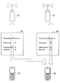
- an eNodeB 21 of an operator A an eNodeB 31 of an operator B, a UE 23 provided with a radio communication service by the operator A, and a UE 33 provided with a radio communication service by the operator B are illustrated.
- the operator A owns the frequency band 25 and the operator B owns the frequency band 35. That is, the frequency band 25 is assigned to the operator A, and the frequency band 35 is assigned to the operator B.
- the frequency band 25 is used for the wireless communication of the UE 23 of the operator A because there is no lease of the frequency band between different operators.
- the frequency band 25 is operated by the operator A's eNodeB 21. That is, communication in the frequency band 25 is controlled by the eNodeB 21 of the operator A.
- the frequency band 35 is used for wireless communication of the UE 33 of the carrier B. Further, the frequency band 35 is operated by the eNodeB 31 of the operator B. In other words, communication in the frequency band 35 is controlled by the eNodeB 31 of the operator B.
- first borrowing method As a method of borrowing a frequency band, there is a first method (hereinafter referred to as “first borrowing method”) in which an eNodeB of an operator who borrows a frequency band to be borrowed operates the frequency band.
- second borrowing technique As a second technique (hereinafter referred to as “second borrowing technique”) in which the eNodeB of the business operator that lent the borrowed frequency band operates the frequency band as a technique for lending the frequency band.
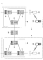
- FIG. 3 is an explanatory diagram for explaining a first lending method in which an eNodeB of a business that borrows a frequency band to be lent operates the frequency band.
- eNodeB 21 of operator A eNodeB 21 of operator A
- eNodeB 31 of operator B UE 23 of operator A
- UE 33 of operator B UE 33 of operator B
- the operator A has a frequency band 25
- the operator B has a frequency band 35.
- the frequency band 25 of the operator A is lent to the operator B. Therefore, the frequency band 25 is used for the wireless communication of the UE 33 of the operator B.
- the rented frequency band 25 is operated by the eNodeB 31 of the operator B that borrows the frequency band 25.
- the radio communication of the UE 33 in the frequency band 25 is controlled by the eNodeB 31 of the operator B, and the communication data of the radio communication passes through the eNodeB 31 of the operator B. That is, the first borrowing method can be said to be a method of borrowing only the frequency band.
- FIG. 4 is an explanatory diagram for explaining a second lending method in which the eNodeB of the business operator that has lent the borrowed frequency band operates the frequency band.
- the frequency band 25 of the operator A is lent to the operator B. Therefore, the frequency band 25 is used for the wireless communication of the UE 33 of the operator B.
- the rented frequency band 25 is operated by the eNodeB 21 of the business operator B that rents the frequency band 25. That is, the radio communication of the UE 33 in the frequency band 25 is controlled by the eNodeB 21 of the operator B, and the communication data of the radio communication passes through the eNodeB 21 of the operator B.
- the second borrowing method can be said to be a method of borrowing the frequency band and entrusting the operation of the frequency band to the lending side.
- a unit of frequency resources in frequency sharing will be described.
- a component carrier unit that is, 12 consecutive subcarrier units
- a subcarrier unit that is, 12 consecutive subcarrier units
- a subcarrier unit that is, 12 consecutive subcarrier units
- borrowing on a CC basis is the easiest.
- CC component carriers
- carrier aggregation a maximum of five 20 MHz wide component carriers (CC) are aggregated, that is, carrier aggregation is specified.
- carrier aggregation a scenario is assumed in which a CC having a low use frequency among a plurality of CCs held by the operator is lent to another operator.
- FIG. 5 is an explanatory diagram for explaining an example of lending and borrowing in component carrier units.
- CC1, CC2, and CC3 held by the operator A and CC4, CC5, and CC6 held by the operator B are shown.
- CC3 among CCs held by the operator A is lent out to the operator B.
- the operator B (UE33 of the operator B) uses four CCs (CC3, CC4, CC5, CC6).
- the serving eNodeB of the UE is considered to be one eNodeB of one operator.
- a system that makes the UE aware of a plurality of operators is considered undesirable from the viewpoint of complexity. Therefore, it is desirable that the CC used is visible to the UE as if it is a CC owned by a single operator.
- the component carrier includes a primary component carrier (PCC) and a secondary component carrier (SCC).
- the UE uses one PCC and, if necessary, one or more SCCs.
- the UE's PCC need not be a specific CC. That is, the PCC of one UE and the PCC of another UE may be different CCs.
- PCC is a CC used when establishing a UE connection. That is, in any one CC, the UE establishes a connection through synchronization on the synchronization channel and cell identification, acquisition of basic system information on the broadcast channel (BCH), and control on the random access channel (RACH). . Any one of the CCs becomes a PCC. SCC is CC added to PCC as needed.
- the synchronization signal includes a primary synchronization signal (PSS) and a secondary synchronization signal (SSS). Thereby, it can communicate using UE about UE corresponding to the release before Release 9 of 3GPP specifications. That is, backward compatibility is ensured.
- PSS primary synchronization signal
- SSS secondary synchronization signal
- the SCC when the SCC is added as a CC used by the UE, it is possible to notify the system information of the SCC by dedicated signaling of the PCC.
- PCC can be changed. That is, it is possible to change the PCC from one CC to another.
- the eNodeB determines which CC is desirable as the PCC for each UE.
- an inter-frequency handover procedure is used.
- the system information of the added SCC is notified to the UE by signaling via the PCC, so the quality of the PCC is important.
- Linkage information between downlink and uplink is specified by system information SIB2 (System Information Block 2).
- SIB2 System Information Block 2
- the linkage information indicates the linkage between the downlink CC and the uplink CC when there are a plurality of downlink CCs and a plurality of uplink CCs. That is, the linkage information indicates which downlink CC and uplink CC are paired.
- PDCCH Physical Downlink Control Channel
- first pattern in which PDCCH exists in each CC
- second pattern in which there is also a CC in which no PDCCH exists.
- the second pattern is a pattern to which so-called cross carrier scheduling is applied.
- the first pattern is a normal pattern to which cross carrier scheduling is not applied.
- FIG. 6 is an explanatory diagram for explaining an example of a normal PDCCH arrangement.
- CC1 and CC2 held by operator A shown in FIG. 5 are shown.
- PDCCH exists in each of CC1 and CC2.
- the scheduling information about CC is transmitted in PDCCH of each CC.
- FIG. 7 is an explanatory diagram for explaining an example of arrangement of PDCCHs when cross-carrier scheduling is applied.
- CC1 has a PDCCH, but CC2 has no PDCCH.
- the scheduling information about CC1 and CC2 is transmitted in PDCCH of CC1.
- the CC in which the PDCCH exists between the macro cell eNodeB and the small cell eNodeB can be alternated, so that the heterogeneous network (Het-Net) ) Is an important technology.
- Het-Net the heterogeneous network
- both the macro cell eNodeB and the small cell eNodeB use CC1 and CC2, for example, if the macro cell eNodeB transmits the PDCCH only in CC1, and the small cell eNodeB transmits the PDCCH only in CC2, the PDCCH It is possible to avoid interference between them. This is called Carrier Aggregation Based ICIC.
- the small cell is a concept including a femto cell, a nano cell, a pico cell, a micro cell, and the like.
- the small cell is a complementary cell for increasing the communication capacity of the macro cell, and can be introduced by installing a smaller eNodeB than the eNodeB of the macro cell.
- CIF Carrier Indication Field
- RRC Radio Resource Control
- PDSCH Physical Downlink Shared Channel
- an upper limit is set in order to reduce the load on the UE.
- 44 CCE Control Channel Element
- 32 CCE is the upper limit.
- the UE When the PDCCH and data do not arrive at the UE for a certain period of time, that is, when communication resources are not allocated to the UE for a certain period of time, the UE automatically performs SCC deactivation.
- the predetermined time is set by the eNodeB.
- any frequency band 25 (ie, CC1, CC2 or CC3) owned by operator A. It is done. More specifically, when the traffic amount of the wireless communication network of the operator B increases rapidly and the traffic amount of the wireless communication network of the operator A is small, the wireless communication system of the operator B increases the bandwidth. , And desires to use the frequency band 25 owned by the operator A.
- FIG. 8 is an explanatory diagram illustrating an example of a schematic configuration of the communication system 1 according to the present embodiment.
- the communication system 1 includes a wireless communication system 2 of an operator A, a wireless communication system 3 of an operator B, and a determination entity 100.
- the wireless communication system 2 of the operator A is, for example, an LTE wireless communication system.
- the wireless communication system 2 includes an EPC (Evolved Packet Core) 40, an eNodeB 200, and a UE 400.
- EPC Evolved Packet Core
- the EPC 40 further includes an S-GW (Serving Gateway) 41, a P-GW (Packet Data Network Gateway) 43, and an MME (Mobility Management Entity) 45.
- the S-GW 41 is connected to one or more eNodeBs, and performs routing and transfer of user data packets.
- the P-GW 43 is connected to an external packet data network, and transfers user data packets between the EPC and the external packet data network.
- the MME 45 is connected to one or more eNodeBs 200, and manages the location of the UE 400, authenticates the UE 400, and the like.
- the eNodeB 200 operates the frequency band 25 owned by the operator A. That is, the eNodeB 200 controls communication in the frequency band 25 and performs radio communication with the UE 400 of the operator A using the frequency band 25.
- the frequency band 35 of the operator B is lent to the operator A.
- ENodeB 200 operates the frequency band 35.
- the eNodeB 200 wirelessly communicates with the UE 400 of the operator A using the frequency band 35.
- the frequency band 25 of the business operator A is lent to the business operator B.
- ENodeB 200 communicates with carrier B UE 500 using radio frequency band 25.
- UE 400 wirelessly communicates with eNodeB 200 of operator A using frequency band 25 owned by operator A.
- the UE 400 when the first lending method (operation by the borrowed operator's eNodeB) is used as the method of lending the frequency band, when the frequency band 35 of the operator B is lent to the operator A, the UE 400 The wireless communication is performed with the eNodeB 200 of the operator A using the frequency band 35 held by the operator B.
- the second lending method (operation by the lending business operator's eNodeB) is used as the frequency bandwidth lending method
- the frequency band 35 of the business operator B is lent to the business operator A
- the UE 400 The wireless communication is performed with the eNodeB 300 of the operator B using the frequency band 35 held by the operator B.
- the wireless communication system 3 of the operator B is, for example, an LTE wireless communication system.
- the wireless communication system 3 includes an EPC (Evolved Packet Core) 50, an eNodeB 300, and a UE 500.
- EPC Evolved Packet Core
- eNodeB 300 eNodeB 300
- UE 500 UE 500
- the determination entity 100 determines whether or not to borrow a frequency band between different operators. The specific operation of the decision entity 100 will be described in more detail later.
- the operator B in the frequency sharing between the operator A and the operator B, the operator B can know whether or not the frequency band of the operator A can be used.
- the operator A can know whether the frequency band of B can be used.
- the specific contents will be described in the modification example >>.
- Configuration of each device >> With reference to FIGS. 9 to 11, configurations of the determination entity 100, the eNodeB 200, and the UE 400 will be described.
- the configuration of eNodeB 300 of operator B is the same as the configuration of eNodeB 200
- the configuration of UE 500 of operator B is the same as the configuration of UE 400.
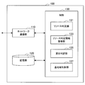
- FIG. 9 is a block diagram illustrating an example of a configuration of the determination entity 100 according to the present embodiment.
- the determination entity 100 includes a network communication unit 110, a storage unit 120, and a control unit 130.
- the network communication unit 110 communicates with a communication node of each operator's wireless communication system. For example, the network communication unit 110 communicates with the MME 45 of the operator A and the MME 55 of the operator B directly or via any communication node. Also, for example, the network communication unit 110 communicates with one or more eNodeBs 200 and one or more eNodeBs 300 directly or via any communication node.
- the storage unit 120 stores a program and data for the operation of the determination entity 100.
- the storage unit 120 includes a storage medium such as a hard disk or a semiconductor memory.
- the control unit 130 provides various functions of the determination entity 100.
- the control unit 130 corresponds to a processor such as a CPU (Central Processing Unit) or a DSP (Digital Signal Processor), and executes the programs stored in the storage unit 120 or another storage medium, thereby executing the various functions described above. I will provide a.
- the control unit 130 includes a resource determination unit 131, a resource determination information acquisition unit 133, a lending determination unit 135, and a base station control unit 137.
- the resource determination unit 131 determines whether or not the frequency band can be used by another provider based on the usage state of the frequency band held by the first provider that provides the wireless communication service. In other words, the resource determination unit 131 determines whether or not the frequency band held by the first operator may be lent.
- the determination is made for each cell of the first operator.
- the resource determination unit 131 determines whether or not each frequency band cell can be used by another operator based on the usage status of each frequency band cell.
- the frequency band is one or more component carriers (CC). Then, the resource determination unit 131 determines whether or not each of the one or more CCs can be used by another operator based on the usage status of each of the one or more CCs held by the first operator. judge.
- each cell 20 is based on the usage status of each CC (CC1, CC2, CC3) of each cell 20 of operator A. It is determined whether or not each CC (CC1, CC2, CC3) can be lent. As a result, it is determined that only the CC3 can be lent out in the cell 20-1 and the cell 20-2 of the operator A, and the CC2 and CC3 can be lent out in the cell 20-3. That is, the determination result is as shown in Table 1 below (OK indicates that lending is possible and-indicates that lending is not possible).
- the resource determination unit 131 determines the necessity of further use of the frequency band by the second operator based on the usage status of another frequency band held by the second operator. In other words, the resource determination unit 131 determines whether the second operator needs to borrow a frequency band of another operator.
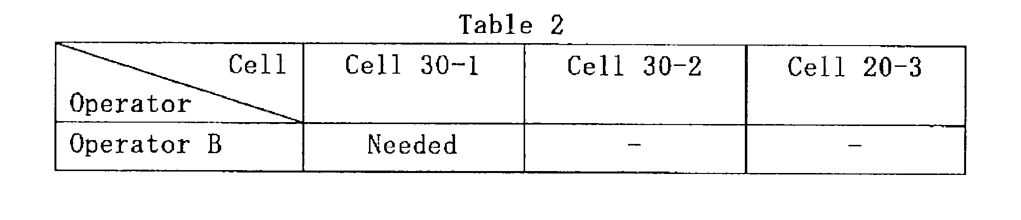
- the determination is also made for each cell of the second operator. That is, the resource determination unit 131 determines whether the second carrier needs to use each cell in a further frequency band based on the usage situation of each cell in another frequency band held by the second carrier. Determine.
- each cell 30 is based on the usage status of each CC (CC4, CC5, CC6) of each cell 30 of the operator B.
- the need for lending at is determined.
- CC of the operator B is required to be lent out in the cell 30-1, and that CC is not required to be lent out in the cells 30-2 and 30-3. That is, the determination result is as shown in Table 2 below (Needed indicates that lending is necessary and-indicates that lending is not necessary).
- the usage status of the frequency band includes the number of UEs in a connection state with the frequency band, the number of UEs to be connected to the frequency band, the usage rate of communication resources in the frequency band, or the above
- the number of UEs in a connection state with the frequency band is, for example, the number of UEs in an RRC (Radio Resource Control) connected state.
- RRC Radio Resource Control
- the number of UEs to be connected to the frequency band is, for example, the number of UEs that are in the RRC idle state and access the eNodeB via the RACH (that is, UEs that are attempting to enter the RRC connected state). Is a number.
- the usage status of each CC is the sum of the number of UEs in the RRC Connected state and the number of UEs attempting to enter the RRC Connected state in the CC.
- the usage status of each CC may be the traffic amount in the CC. In this case, for example, if the traffic volume in CC3 of cell 20-1 exceeds the threshold value, it is determined that CC3 of cell 20-1 cannot be lent, and if not, CC1 of cell 20-1 can be lent. It is determined that
- the usage status of the frequency band may be whether or not new access by the UE is prohibited in the frequency band. Whether or not the new access is prohibited is, for example, whether or not access barring in the system information is valid. As an example, when access barring is effective in two or more CCs CC4, CC5, and CC6 in the cell 30-1, it is determined that the CC 30 is required to be lent out in the cell 30-1 of the operator B. Otherwise, it is determined that the CC 30 need not be lent out in the cell 30-1.
- the resource determination information acquisition unit 133 acquires determination information indicating the result of determination by the resource determination unit 131. First, the resource determination information acquisition unit 133 determines whether or not the frequency band can be used by another provider based on the usage status of the frequency band held by the first provider that provides the wireless communication service. Determination information indicating the result (hereinafter referred to as “usability determination information”) is acquired. In other words, the resource determination information acquisition unit 133 acquires availability determination information indicating whether or not the frequency band held by the first operator may be lent.
- the determination is made for each cell of the first operator. That is, the resource determination information acquisition unit 133 determines whether or not each cell can use the frequency band based on the usage state of each cell in the frequency band. To get.
- the frequency band is one or more component carriers (CC). Then, the resource determination information acquisition unit 133 uses each of the one or more CCs by another operator based on the usage status of each of the one or more CCs held by the first operator. Determination information for each CC indicating the result of determining availability is acquired.
- the availability determination information for example, “OK” or “ ⁇ ” described above
- the availability determination information for example, “OK” or “ ⁇ ” described above
- the resource determination information acquisition unit 133 needs to use a further frequency band by the second operator based on the usage status of another frequency band held by the second operator. Further determination information (hereinafter referred to as “necessity determination information”) indicating the result of determining the sex is acquired. In other words, the resource determination information acquisition unit 133 acquires necessity determination information indicating whether the second operator needs to borrow a frequency band of another operator.
- the determination is also made for each cell of the second operator. That is, the resource determination information acquisition unit 133 needs to use each cell in a further frequency band by the second operator based on the usage status of each cell in another frequency band held by the second operator. Necessity determination information for each cell indicating the result of determining the sex is acquired.
- necessity determination information for example, “Needed” or “ ⁇ ” described above
- necessity determination information for example, “Needed” or “ ⁇ ” described above
- the lending determination unit 135 determines whether to allow the second operator to use the frequency band held by the first operator, based on the acquired use availability determination information. In other words, the lending determination unit 135 determines the frequency band held by the first operator based on whether or not the frequency band held by the first operator may be lent. Determine whether to lend to.
- the lending determination unit 135 determines whether to allow the second operator to use the frequency band for each cell based on the availability determination information for each cell. In addition, for example, the lending determination unit 135 determines which one of the one or more CCs is to be used by the second operator based on the obtained use determination information for each CC.
- the availability determination information for each CC of each cell 20 of operator A as shown in the determination result of availability of Table 1 is acquired.
- the lending determination unit 135 determines to lend CC3 in the cell 20-1 and the cell 20-2 and lend at least one CC of CC2 and CC3 in the cell 20-3.
- the second operator can know which frequency can be used in what region and at what timing. That is, the second operator can know whether the frequency band of the first operator can be used.
- frequency resources can be used more effectively from the viewpoint of the area.
- frequency resources can be used more effectively from the viewpoint of frequency.
- the lending determination unit 135 determines whether to allow the second operator to use the frequency band of the first operator based on the availability determination information and the necessity determination information. In other words, the lending determination unit 135 determines whether or not the frequency band held by the first operator may be lent and whether or not the second operator needs to borrow the frequency band of another operator. Based on the above, it is determined whether or not the second operator uses the frequency band of the first operator.
- the lending determination unit 135 confirms from the necessity information which cell 30 (of the second operator) needs to borrow the frequency band of another operator.
- the lending determination unit 135 specifies the cell 20 (of the first operator) located in the vicinity of the cell 30.
- the lending determination unit 135 confirms from the availability determination information which cell 20 of the identified cells 20 the frequency band may be lent to another operator.
- the lending determination unit 135 determines to lend the frequency band of the cell 20 to the operator B if the frequency band of the cell 20 may be lent.
- the lending determination unit 135 confirms from the necessity information that it is necessary to borrow the frequency band of the operator A in the cell 30-1.
- the lending determination unit 135 identifies the first operator's cell 20-1, cell 20-2, and cell 20-3 located in the vicinity of the cell 30-1.
- the lending determination unit 135 indicates that only CC3 may be lent out in the cells 20-1 and 20-2, and CC2 and CC3 may be lent out in the cell 20-3.
- the lending judgment unit 135, for the cell 30-1 of the carrier B, out of CC3 of the cell 20-1, CC3 of the cell 20-2, CC3 of the cell 20-3 and CC2 of the cell 20-3 It determines with lending one or more CC to the provider B.
- the neighbor relationship between cells of different operators is stored in advance by the determination entity 100. Yes. Or the said proximity
- the second borrowing method frequency band operation by the lending operator's eNodeB
- the number of CCs corresponding to the communication capacity further required in the cell 30-1 may be selected at random.
- the number of CCs corresponding to the communication capacity further required in the cell 30-1 may be selected in order from the CC of the cell 20 that is close to the cell 30-1. That is, CCs may be selected in the order of CC3 of the cell 20-1, CC3 of the cell 20-3, CC2 of the cell 20-3, and CC3 of the cell 20-2.
- the cell 20 that uses the borrowed frequency band and the cell that uses the same frequency band in the vicinity thereof It is desirable that the CC is selected so that the interference with 30 is smaller.
- the same CC of one or more cells 20 that partially or entirely overlap with the cell 30-1 may be selected. That is, CC3 of the cell 20-1, the cell 20-2, and the cell 20-3 may be selected. By such selection, interference can be reduced even if the first lending method is used as the method of lending the frequency band.
- the frequency band is It is determined to lend to a second operator. Therefore, the second operator can borrow a frequency band only when necessary. That is, since the borrowing of the frequency band can be minimized, the exchange of information between the business operators due to the borrowing of the frequency band can be minimized. In addition, it is possible to avoid a shortage of frequency bands in a business operator who owns the frequency bands due to lending of many frequency bands.
- Base station control unit 137 When it is determined that the second carrier uses the frequency band of the first cell of the first operator, the base station control unit 137 causes the eNodeB of the first cell to send the first cell The use of the frequency band by the UE of the first operator in the cell is stopped. More specifically, for example, when it is determined that the CC3 of the cell 20-1 of the operator A is lent to the operator B, the base station control unit 137 transmits the cell 20 to the eNodeB 200-1 of the cell 20-1. The use of CC3 by UE 400 in ⁇ 1 is stopped.
- the base station control unit 137 transmits, via the network communication unit 110, a processing instruction for stopping the use of the lent CC3 to the eNodeB 200-1 that rents the CC3, whereby the cell 20-1 The use of CC3 by the UE 400 is stopped.
- the frequency band lent from the first operator is not used by the UE of the first operator (that is, released), and the frequency band is used as the second operator. It is possible to lend to. As a result, the second operator can actually use the rented frequency band. For example, when several UEs 400 are using CCs lent out by the operator A, the CCs are operated in a state where the CCs are not used by the several UEs 400 (and another new UE 400). It is possible to lend to person B. As a result, the rented CC can be actually used by the UE of the operator B (for example, 100 UEs).
- a specific method for stopping the use of such a frequency band (hereinafter referred to as a stop method) will be described.
- a stop method it is assumed that the CC3 of the cell 20-1 of the operator A is determined to be lent to the operator B as described above.
- the base station control unit 137 causes the eNodeB of the first cell to notify the UE of the first operator of a new access prohibition in the frequency band. More specifically, for example, the base station control unit 137 causes the eNodeB 200-1 to notify the UE 400 of prohibition of new access in CC3. For example, the eNodeB 200-1 notifies the UE 400 of prohibition of new access in the CC3 by enabling access barring in the system information of the CC3. By such notification, it is possible to prevent the UE of the business operator that lent the frequency band from newly using the rented frequency band. For example, if the first operator's radio communication system is an LTE-A radio communication system, the UE establishes a new connection in the leased CC, and the CC is newly used as a PCC. Can be prevented.
- the first operator's radio communication system is an LTE-A radio communication system
- the UE of the first operator can perform wireless communication using one main frequency band and one or more auxiliary frequency bands, and the frequency band possessed by the first operator is the main frequency band described above. Used as a frequency band or the auxiliary frequency band.
- the UE 400 performs wireless communication using one PCC and one or more SCCs. Is possible. CC1, CC2, and CC3 are used as PCC or SCC.
- the base station control unit 137 may change the UE of the first operator who uses the frequency band as a primary frequency band to the eNodeB of the first cell. Handover to the frequency band. More specifically, for example, the base station control unit 137 causes the eNodeB 200-1 to perform handover of the UE 400 using CC3 as the PCC to another CC (for example, CC1 or CC2). By such a handover, it is possible to eliminate UEs that use the lent frequency band as the main frequency band. That is, the rented frequency is used only as a secondary frequency band. For example, if the first operator's radio communication system is an LTE-A radio communication system, it is possible to eliminate UEs that use lent CCs as PCCs. That is, the lent CC is used only as an SCC.
- the base station control unit 137 communicates with the UE of the first operator that uses the frequency band as the auxiliary frequency band for the eNodeB of the first cell. Stop resource allocation. More specifically, for example, the base station control unit 137 causes the eNodeB 200-1 to stop allocating communication resources to the UE 400 that uses CC3 as the SCC. By stopping the communication resource allocation as described above, it is possible to eliminate the UE that uses the lent frequency band as the auxiliary frequency band. For example, if the first operator's wireless communication system is an LTE-A wireless communication system, the SCC is deactivated if communication resources are not allocated for a certain period of time. UE used as SCC can be eliminated.
- the base station control unit 137 may link the other frequency band having the link direction different from the link direction of the frequency band and the frequency band to the eNodeB of the first cell.
- the base station control unit 137 causes the eNodeB 200-1 to update the linkage between another CC (CC1 or CC2) having a link direction different from CC3 and CC3.
- the eNodeB 200-1 updates the linkage information of the SIB2.
- the base station control unit 137 When the use suspension of the rented frequency band is completed, the base station control unit 137 is notified by the eNodeB 200 of the completion of the use stop. Thereafter, a preparation for use of the frequency band is performed by the second operator lent out the frequency band.
- the base station control unit 137 transfers the second operator to the eNodeB that uses the frequency band.
- the use of the frequency band by the UE may be stopped.
- FIG. 10 is a block diagram illustrating an example of the configuration of the eNodeB 200 according to the present embodiment.
- the eNodeB 200 includes a wireless communication unit 210, a network communication unit 220, a storage unit 230, and a control unit 240.
- the radio communication unit 210 performs radio communication with the UE in the cell using the frequency band. More specifically, for example, the radio communication unit 210 uses the frequency band 25 (CC1, CC2, or CC3) held by the operator A in the cell 20 of the eNodeB 200 and wirelessly communicates with the UE 400 of the operator A. connect.
- the frequency band 25 CC1, CC2, or CC3 held by the operator A in the cell 20 of the eNodeB 200 and wirelessly communicates with the UE 400 of the operator A. connect.
- the first borrowing technique frequency band operation by the borrower's eNodeB
- the wireless communication unit 210 uses the frequency band 35 (CC4, CC5, or CC6) held by the operator B in the cell 20 of the eNodeB 200.
- the frequency band 35 CC4, CC5, or CC6
- the second borrowing technique frequency band operation by the lending business operator's eNodeB
- the wireless communication unit 210 uses the frequency band 25 (CC1, CC2, or CC3) held by the operator A in the cell 20 of the eNodeB 200.
- the UE 500 of the operator B may be used.
- the wireless communication unit 210 includes, for example, an antenna and an RF circuit.
- the network communication unit 220 communicates with other communication nodes. For example, the network communication unit 220 communicates with the S-GW 41, the P-GW 43, and the MME 45 directly or via any communication node. Further, for example, the network communication unit 220 communicates with the determination entity 100 directly or via any communication node.
- the storage unit 230 stores a program and data for the operation of the eNodeB 200.
- the storage unit 230 includes a storage medium such as a hard disk or a semiconductor memory.
- Control unit 240 provides various functions of the eNodeB 200.
- the control unit 240 corresponds to a processor such as a CPU or a DSP, and provides the various functions described above by executing a program stored in the storage unit 230 or another storage medium.
- the control unit 240 controls the frequency band of the UE 400 of the carrier A in the cell of the eNodeB 200 according to the control of the determination entity 100. Stop using 25. Note that the use of the frequency band is stopped by, for example, the first to fourth stop methods described above.
- the base station control unit 240 also allows the UE of the carrier who borrowed the frequency band to Stop using the frequency band.
- FIG. 11 is a block diagram showing an example of the configuration of the UE 400 according to the present embodiment.
- the UE 400 includes a radio communication unit 410, a storage unit 420, and a control unit 430.
- the wireless communication unit 410 performs wireless communication with the eNodeB using the frequency band. More specifically, for example, the wireless communication unit 410 uses the frequency band 25 (CC1, CC2, or CC3) held by the operator A in the cell 20 of the operator A, and the eNodeB 200 of the cell 20 Wireless communication.
- the frequency band 25 CC1, CC2, or CC3 held by the operator A in the cell 20 of the operator A, and the eNodeB 200 of the cell 20 Wireless communication.
- the first borrowing technique frequency band operation by the borrower's eNodeB
- the wireless communication unit 410 includes the frequency band 35 (CC4, CC4) held by the operator B in the cell 20 of the eNodeB 200 of the operator A.
- CC5 or CC6 is used to communicate wirelessly with eNodeB 200 of operator A.
- the second borrowing technique frequency band operation by the lending business operator's eNodeB
- the wireless communication unit 410 includes the frequency band 35 (CC4, CC4) held by the operator B in the cell 30 of the eNodeB 300 of the operator B.
- CC5 or CC6 is used to communicate wirelessly with eNodeB 300 of operator B.
- the wireless communication unit 410 includes, for example, an antenna and an RF circuit.
- the storage unit 420 stores a program and data for the operation of the UE 400.
- the storage unit 420 includes a storage medium such as a hard disk or a semiconductor memory.
- Control unit 430 provides various functions of the UE 400.
- the control unit 430 corresponds to a processor such as a CPU or a DSP, and provides the various functions described above by executing a program stored in the storage unit 420 or another storage medium.
- the control unit 430 stops using the frequency band 25 in the cell of the eNodeB 200 in accordance with the control of the eNodeB 200.
- the frequency band is lent
- the UE 400 uses the rented frequency band
- the control unit 430 stops using the frequency band when the rent of the frequency band is finished thereafter.
- FIG. 12 is a flowchart illustrating an example of a schematic flow of determination processing by the determination entity 100 according to the present embodiment.
- the resource determination unit 131 connects the UEs in the connection state of each component carrier (CC) in each cell of each operator (operator A, operator B) via the network communication unit 110. Receive number information. In step S603, the resource determination unit 131 also receives information on the number of UEs to be connected to each CC in each cell of each operator via the network communication unit 110.
- step S605 the resource determination unit 131 lends each CC in each cell of each operator based on the information on the number of UEs in the connected state and the information on the number of UEs to be connected. Judgment is made. Further, in step S607, the resource determination unit 131 determines whether or not each operator needs to borrow a CC based on the information on the number of UEs in the connected state and the information on the number of UEs to be connected. Determine. That is, the resource determination unit 131 generates usability determination information and necessity determination information.
- step S609 the lending determination unit 135 determines whether the operator B uses each CC of the operator A based on the availability determination information of the operator A and the necessity determination information of the operator B. .
- step S611 the lending determination unit 135 determines whether the operator B is allowed to use each CC of the operator A based on the availability determination information of the operator B and the necessity determination information of the operator A. . Then, the process ends.
- FIG. 13 is a flowchart illustrating an example of a schematic flow of frequency band use stop processing by the determination entity 100 according to the present embodiment.
- step S ⁇ b> 701 the base station control unit 137 lends the CC to the processing instruction for stopping the use of the lent CC (hereinafter referred to as “target CC”) via the network communication unit 110. It transmits to eNodeB200.
- target CC the processing instruction for stopping the use of the lent CC
- step S703 the base station control unit 137 is notified of the completion of the use suspension from the eNodeB 200. Then, the process ends. After that, preparations are made for the operator B to use the lent CC.
- FIG. 14 is a flowchart showing an example of a schematic flow of frequency band use stop processing by the eNodeB 200 according to the present embodiment.
- step S801 the control unit 240 receives a processing instruction for stopping the use of the target CC from the determination entity 100 via the network communication unit 220.
- step S803 the control unit 240 enables access barring in the system information of the target CC.
- step S805 the control unit 240 performs handover of the UE 400 using the target CC as the PCC to another CC.
- step S807 the control unit 240 stops assigning communication resources to the UE 400 that uses the target CC as the SCC.
- step S809 the control unit 240 updates the linkage between another CC having a different link direction from the target CC and the target CC.
- step S811 the determination entity 100 is notified of the completion of the suspension of use of the target CC. Then, the process ends.
- FIG. 15 is an explanatory diagram for explaining an example of borrowing of a frequency band between operators.
- the cell 20 of the operator A and the cell 30 of the operator B are shown.
- CC1 of the cell 20-1 is lent to the cell 30-1 of the operator B.
- eNodeB 300-1 of cell 30-1 of operator B operates CC1 and communicates with UE 500 of operator B in cell 30-1 using CC1.
- CC1 is not lent to the operator B. Therefore, the eNodeB 200-2 of the cell 20-2 of the operator A also uses the CC1 and the UE 400 of the operator A in the cell 20-2. Communicate with. Also in cell 20-3, CC1 is not lent to carrier B, so eNodeB 200-3 of carrier A's cell 20-3 also uses UE1 of carrier A in cell 20-3. Communicate with.
- FIG. 16 is an explanatory diagram for explaining an example of interference between cells of different operators due to lease of a frequency band.
- interference may occur in CC1 between cells 20-2 and 30-1 that partially overlap each other.
- interference may occur in CC1 between cells 20-3 and 30-1 that partially overlap each other.
- Inter-cell interference control Inter-cell Interference control
- Inter-Cell Interference Coordination of 3GPP Specification Release 8
- transmission power information is shared between adjacent cells for each resource block (12 subcarriers ⁇ 7 OFDM symbols) in the downlink. This information is called RNTP (Relative Narrowband Transmit Power) Indicator.
- RNTP Relative Narrowband Transmit Power
- the eNodeB of the adjacent cell can predict the degree of interference in each resource block by receiving the RNTP. Note that the processing executed by the eNodeB after the prediction of the degree of interference is not standardized in the specification and depends on the implementation.
- OI Overload Indicator
- HII High Interference Indicator
- the ICIC as described above is a method of interference control within the same operator, on the assumption that an X2 interface exists between cells of the same operator. Therefore, it cannot be applied as it is to the interference between cells of different operators due to the borrowing of the frequency band as described with reference to FIG.
- Modification method Therefore, in the modification of the present embodiment, an X2 interface between different providers is provided, and information for interference suppression in the rented frequency band is transmitted / received via the X2 interface.
- the frequency band of the first cell of the first operator when it is determined that the frequency band of the first cell of the first operator is to be used by the second operator, the frequency band at least partially overlaps the first cell.
- the second operator's second cell eNodeB for communication with the second operator's UE. More specifically, for example, as shown in FIG. 15, when it is determined that the operator B uses the CC1 of the cell 20-1 of the operator A, the CC1 is at least one in the cell 20-1.
- the eNodeB 300-1 of the overlapping cell 30-1 is used for communication with the UE 500 of the carrier B.
- interference suppression information Information for suppression
- the eNodeB 200-2 and eNodeB 200-3 of the operator A and the eNodeB 300-1 of the operator B transmit and receive interference suppression information in CC1 via the X2 interface.
- FIG. 17 is an explanatory diagram for explaining an example of the X2 interface between different operators.
- an X2 interface is provided between operator A's eNodeB 200 and operator B's eNodeB 300.
- the X2 interface is a logical interface.
- the eNodeB 200 and the eNodeB 300 communicate with each other via the X2 interface directly or via any one of the communication nodes.
- various information such as information for each resource block and scheduling information is transmitted and received through the X2 interface within the same carrier.
- the information transmitted / received via the X2 interface between different operators should be less than the information transmitted / received via the X2 interface within the same operator. is there.
- the interference suppression information in the frequency band includes information indicating which partial band communication resources of a plurality of partial bands included in the frequency band are allocated to the UE located at the end of the cell. Including. More specifically, for example, each eNodeB (control unit of each eNodeB) divides CC1 into a plurality of partial bands (for example, three partial bands) and allocates communication resources of any partial band among the plurality of partial bands. Decide whether to assign to UEs located at the edge of the cell. Each eNodeB transmits information indicating the determined partial band as interference control information via the X2 interface between different operators. For example, each eNodeB transmits the interference suppression information quasi-statically. Dividing the frequency band in this way is called “Partial Frequency Reuse”.
- the CC1 interference suppression information transmitted by the eNodeB 300-1 is information indicating a partial band used by the UE 500 located at the end of the cell 30-1 among the three partial bands of CC1. It is.
- the CC1 interference suppression information transmitted by the eNodeB 200-2 is information indicating a partial band used by the UE 400 located at the end of the cell 20-2 among the three partial bands of CC1.
- Such information makes it possible to predict at which frequency in the frequency band the interference will increase, so that it is also possible to suppress the interference.
- information exchanged between different operators can be suppressed.
- the second lending method instead of the first lending method. That is, in the alternative method, when it is determined that the second carrier uses the frequency band of the first cell of the first operator, the frequency band is set by the base station of the first cell. , Used for communication with the UE of the second operator. More specifically, when it is determined that the operator B uses CC1 of the cell 20-1 of the operator A, the CC1 communicates with the UE 500 of the operator B by the eNodeB 200-1 of the cell 20-1. Used for communication. That is, data transmitted / received by CC1 of operator B on CC1 passes through eNodeB 200-1 of operator A.
- the second lending method it is possible to suppress interference in the frequency band by the X2 interface between cells of the same operator. That is, ICIC can be used. For this reason, it is possible to suppress interference due to the borrowing of frequency bands between different operators.
- the second operator can know which frequency can be used in what region and at what timing. That is, the second operator can know whether the frequency band of the first operator can be used.
- the second carrier is allowed to use the frequency band for each cell.
- frequency resources can be used more effectively from an area perspective.
- each component carrier CC
- the frequency band is It is determined to lend to a second operator. Therefore, the second operator can borrow a frequency band only when necessary. That is, since the borrowing of the frequency band can be minimized, the exchange of information between the business operators due to the borrowing of the frequency band can be minimized. In addition, it is possible to avoid a shortage of frequency bands in a business operator who owns the frequency bands due to lending of many frequency bands.
- the eNodeB of the first cell transmits the first cell in the first cell.
- the use of the frequency band by the UE of one operator is stopped.
- the frequency band lent from the first operator is not used by the UE of the first operator (that is, released), and the frequency band is used as the second operator. It is possible to lend to. As a result, the second operator can actually use the rented frequency band. For example, when several UEs 400 are using CCs lent out by the operator A, the CCs are operated in a state where the CCs are not used by the several UEs 400 (and another new UE 400). It is possible to lend to person B. As a result, the rented CC can be actually used by the UE of the operator B (for example, 100 UEs).
- a new access prohibition in the frequency band is notified to the UE of the first operator.
- Such notification can prevent the UE of the carrier that lent the frequency band from newly using the rented frequency band.
- the first operator's radio communication system is an LTE-A radio communication system
- the UE establishes a new connection in the leased CC, and the CC is newly used as a PCC. Can be prevented.
- the handover of the UE of the first operator using the above frequency band as the primary frequency band to another frequency band is performed.
- Such a handover can eliminate UEs that use the lent frequency band as the main frequency band. That is, the rented frequency is used only as a secondary frequency band.
- the first operator's radio communication system is an LTE-A radio communication system
- a third stop method for example, the allocation of communication resources to the UE of the first operator using the frequency band as the auxiliary frequency band is stopped.
- Such a suspension of communication resource allocation can eliminate UEs that use the lent frequency band as an auxiliary frequency band.
- the SCC is deactivated if communication resources are not allocated for a certain period of time. UE used as SCC can be eliminated.
- a linkage between another frequency band having a link direction different from the link direction of the frequency band and the frequency band is updated.
- the frequency band lent out from the first operator can be made independent of another frequency band owned by the first operator.
- the determination entity is a device located between the wireless communication systems of different operators, but the present technology is not limited to such an example.
- the decision entity may be a new device included in any operator's wireless communication system, or an existing device (eg, MME, S-GW, eNodeB, etc.) may be implemented as a new function.
- the operator's wireless communication system is an LTE-A wireless communication system
- the operator's wireless communication system is not limited thereto.
- the operator's wireless communication system may be a wireless communication system similar to LTE-A, or a wireless communication system compliant with a standard further developed from LTE-A.
- the cell base station is an LTE-Advanced eNodeB, but the present technology is not limited to this example.
- the base station may be a base station that complies with another communication standard.
- the terminal device that communicates in the cell is an LTE-Advanced UE, but the present technology is not limited to this example.
- the terminal device may be a terminal device that complies with another communication standard.
- processing steps in the communication control processing of this specification do not necessarily have to be executed in time series in the order described in the flowchart.
- the processing steps in the communication control process may be executed in an order different from the order described in the flowchart, or may be executed in parallel.
- a base station, or a terminal device perform functions equivalent to the respective configurations of the communication control device, the base station, or the terminal device.
- Computer programs can also be created.
- a storage medium storing the computer program is also provided.
- An acquisition unit that acquires determination information indicating a result of determining whether or not the frequency band can be used by another provider based on the usage state of the frequency band held by the first provider that provides the wireless communication service;
- a determination unit that determines whether the second operator uses the frequency band based on the acquired determination information;
- a communication control device comprising: (2) The acquisition unit acquires determination information for each cell indicating a result of determining whether or not each frequency band cell can be used by another operator based on a usage situation for each cell of the frequency band, The determination unit determines whether the second operator uses the frequency band for each cell based on the determination information for each cell.
- the communication control device according to (1).
- the base station of the first cell causes the base station of the first cell to The communication control device according to (2), further including a control unit that stops the use of the frequency band by the terminal device of the first provider.
- the communication control device according to (3) wherein the control unit causes the base station of the first cell to notify the terminal device of prohibition of new access in the frequency band.
- the terminal device is capable of wireless communication using one main frequency band and one or more auxiliary frequency bands, The frequency band is used as the main frequency band or the auxiliary frequency band.
- the control unit causes the base station of the first cell to perform a handover to another frequency band of the terminal device using the frequency band as the main frequency band. Communication control device. (7) The control unit causes the base station of the first cell to stop allocating communication resources to the terminal device using the frequency band as the auxiliary frequency band, according to (5) or (6) The communication control device described. (8) The control unit causes the base station of the first cell to update a linkage between another frequency band having a link direction different from the link direction of the frequency band and the frequency band, (4) to (7) The communication control apparatus according to any one of the above. (9) When it is determined that the second operator uses the frequency band of the first cell of the first operator, the frequency band overlaps at least partially with the first cell.
- the base station of the first operator and the base station of the second operator are connected via the interface between the base station of the first operator and the base station of the second operator.
- Sending and receiving information for interference suppression in the frequency band The communication control apparatus according to any one of (2) to (8).
- the information for interference suppression in the frequency band is information indicating which partial band communication resources of a plurality of partial bands included in the frequency band are allocated to the terminal device located at the end of the cell.
- the communication control device according to any one of (2) to (8), which is used for communication with a terminal device of a business operator.
- the usage status of the frequency band includes the number of terminal devices connected to the frequency band, the number of terminal devices to be connected to the frequency band, the usage rate of communication resources in the frequency band, or the frequency band.
- (1) to (11) wherein the measured value or the actual value of at least one of the traffic amounts in the network is a value derived from the measured value or the actual value.
- Communication control device (13) The communication control device according to any one of (1) to (11), wherein the usage status of the frequency band is whether or not new access by a terminal device is prohibited in the frequency band.
- the acquisition unit includes further determination information indicating a result of determining the necessity of use of a further frequency band by the second operator based on a use situation of another frequency band held by the second operator. Acquired, The determination unit determines whether to cause the second operator to use the frequency band based on the determination information and the further determination information.
- the communication control apparatus according to any one of (1) to (13).
- the frequency band is one or more component carriers; The acquisition unit determines whether or not each of the one or more component carriers can be used by another operator based on the usage status of each of the one or more component carriers held by the first operator.
- the determination unit determines which component carrier of the one or more component carriers is to be used by the second operator based on the acquired determination information for each component carrier.
- the communication control apparatus according to any one of (1) to (14).
- (16) A wireless communication unit that wirelessly communicates with a terminal device using a frequency band held by the first operator in a first cell of a first operator that provides a wireless communication service; Based on the determination information for each cell indicating the result of determining whether or not the frequency band can be used for each cell by another operator based on the usage status for each cell of the frequency band, the frequency band for each cell is When it is determined whether to use the second carrier, when it is determined that the second carrier uses the frequency band of the first cell, according to the control by the communication control device, A control unit for stopping the use of the frequency band by the terminal device of the first operator in the first cell;
- a base station comprising: (17) Wireless communication that wirelessly communicates with a base station of the first cell using a frequency band held by the first carrier within a first
- a control unit for stopping the use of the frequency band in the first cell comprising: (18) Obtaining determination information indicating a result of determining whether or not the frequency band can be used by another provider based on the usage state of the frequency band held by the first provider that provides the wireless communication service; Determining whether to allow the second operator to use the frequency band based on the acquired determination information; Including a communication control method.
Landscapes
- Engineering & Computer Science (AREA)
- Computer Networks & Wireless Communication (AREA)
- Signal Processing (AREA)
- Quality & Reliability (AREA)
- Mobile Radio Communication Systems (AREA)
Abstract
Description
1.はじめに
1.1.周波数リソースの有効利用のための技術分野
1.2.異なる事業者間での周波数シェアリング
1.3.キャリアアグリゲーションの概要
1.4.技術的課題
2.無線通信システムの構成
3.各装置の構成
3.1.判定エンティティの構成
3.2.eNodeBの構成
3.3.UEの構成
4.処理の流れ
4.1.判定処理
4.2.使用停止処理
5.変形例
6.まとめ
まず、図1~図7を参照して、周波数リソースの有効利用のための技術分野、異なる事業者間での周波数シェアリング、キャリアアグリゲーションの概要、及び技術的課題を説明する。
まず、周波数リソースの有効利用のための技術分野を説明する。周波数リソースの有効利用のための技術分野として、例えば、以下のような技術分野が代表的である。
・単一の事業者内での周波数シェアリング
・異なる事業者間での周波数シェアリング
・時間的に又は空間的に遊休状態の周波数リソースを有効活用する周波数2次利用
・遊休状態の周波数リソースのリアルタイムオークション
次に、図1~図5を参照して、異なる事業者間での周波数シェアリングを説明する。上述したように、異なる事業者の通信システム間で周波数リソースが貸借される。また、異なる事業者(例えば、事業者A及び事業者B)が同時に同じエリアで無線通信サービスを提供していると仮定される。
図1は、2つの事業者の無線通信サービスのエリアの一例を説明するための説明図である。図1を参照すると、事業者Aの無線通信サービスのエリアを形成する事業者Aのセル20、及び事業者B無線通信サービスのエリアを形成する事業者Bのセル30が示されている。また、事業者Aのセル20の中心には、事業者AのeNodeB21が位置し、事業者Bのセル30の中心には、事業者BのeNodeB31が位置する。例えばこのように、事業者AのeNodeB21と事業者BのeNodeB31とが近傍に配置されると、事業者A及び事業者Bが同時に同じエリアでLTE-Aの無線通信サービスを提供することになる。なお、eNodeBの配置は、事業者ごとに行われる。
周波数帯域の貸借の手法として、まず、貸借対象の周波数帯域を借りた事業者のeNodeBが当該周波数帯域を運用する第1の手法(以下、「第1の貸借手法」と呼ぶ)がある。また、周波数帯域の貸借の手法として、貸借対象の周波数帯域を貸し出した事業者のeNodeBが当該周波数帯域を運用する第2の手法(以下、「第2の貸借手法」と呼ぶ)もある。以下、これらの貸借手法について図3及び4を参照してより具体的に説明する。
次に、周波数シェアリングにおける周波数リソースの単位を説明する。周波数リソースの貸借の単位として、コンポーネントキャリア単位、リソースブロック単位(即ち、12個の連続するサブキャリア単位)、サブキャリア単位等が考えられる。事業者間での詳細な情報のやり取りは望ましくないので、CC単位の貸借が最も容易であると考えられる。
ある事業者から別の事業者へCCが貸し出され、当該別の事業者(当該別の事業者のUE)により当該CCが使用される場合に、上記ある事業者のUEが当該CCを使用できないことが望ましい。例えば、図5に示される例において、CC3が貸し出されている間は、事業者AのUE23がCC3を使用できないことが望ましい。なぜならば、異なる事業者に属するUEが1つのコンポーネントキャリアを使用すると、事業者Aの無線通信システムと事業者Bの無線通信システムとの間で様々な情報をやり取りする必要があり、これは望ましくないからである。
基本的には、UEのサービングeNodeBは、1つの事業者の1つのeNodeBであると考えられる。また、UEに複数の事業者を意識させるようなシステムは、複雑さの観点から望ましくないと考えられる。したがって、使用されるCCは、単一の事業者により保有されるCCであるかのようにUEから見えることが望ましい。
次に、図6及び図7を参照して、キャリアアグリゲーションの概要を説明する。
上述した異なる事業者間での周波数シェアリングを実装する場合の技術的課題を説明する。ここでは、一例として、上述したリリース10のキャリアアグリゲーションの技術が適用されるLTE-Aのプラットフォーム上で、上記周波数シェアリングが実装される場合を説明する。
まず、図8を参照して、本開示の実施形態に係る通信システム1の概略的な構成について説明する。図8は、本実施形態に係る通信システム1の概略的な構成の一例を示す説明図である。図8を参照すると、通信システム1は、事業者Aの無線通信システム2、事業者Bの無線通信システム3及び判定エンティティ100を含む。
事業者Aの無線通信システム2は、例えば、LTEの無線通信システムである。無線通信システム2は、EPC(Evolved Packet Core)40、eNodeB200及びUE400を含む。
事業者Bの無線通信システム3は、例えば、LTEの無線通信システムである。無線通信システム3は、EPC(Evolved Packet Core)50、eNodeB300及びUE500を含む。例えば、事業者Bの無線通信システム3の各装置は、事業者Aの無線通信システム2の対応する装置と同様に動作する。
判定エンティティ100は、異なる事業者間での周波数帯域の貸借の判定を行う。判定エンティティ100の具体的な動作は後により詳細に説明される。
図9~図11を参照して、判定エンティティ100、eNodeB200及びUE400の構成を説明する。なお、例えば、事業者BのeNodeB300の構成はeNodeB200の構成と同様であり、事業者BのUE500の構成はUE400の構成と同様である。
図9を参照して、本実施形態に係る判定エンティティ100の構成の一例について説明する。図9は、本実施形態に係る判定エンティティ100の構成の一例を示すブロック図である。図9を参照すると、判定エンティティ100は、ネットワーク通信部110、記憶部120及び制御部130を備える。
ネットワーク通信部110は、各事業者の無線通信システムの通信ノードと通信する。例えば、ネットワーク通信部110は、直接的に又はいずれかの通信ノードを介して、事業者AのMME45及び事業者BのMME55と通信する。また、例えば、ネットワーク通信部110は、直接的に又はいずれかの通信ノードを介して、1つ以上のeNodeB200及び1つ以上のeNodeB300と通信する。
記憶部120は、判定エンティティ100の動作のためのプログラム及びデータを記憶する。記憶部120は、例えばハードディスク又は半導体メモリ等の記憶媒体を含む。
制御部130は、判定エンティティ100の様々な機能を提供する。例えば、制御部130は、CPU(Central Processing Unit)又はDSP(Digital Signal Processor)等のプロセッサに相当し、記憶部120又は他の記憶媒体に記憶されるプログラムを実行することにより、上記様々な機能を提供する。制御部130は、リソース判定部131、リソース判定情報取得部133、貸出判定部135及び基地局制御部137を含む。
リソース判定部131は、無線通信サービスを提供する第1の事業者により保有される周波数帯域の使用状況に基づいて、別の事業者による当該周波数帯域の使用の可否を判定する。換言すると、リソース判定部131は、上記第1の事業者により保有される周波数帯域が貸し出されてもよいか否かを判定する。

リソース判定情報取得部133は、リソース判定部131による判定の結果を示す判定情報を取得する。第1に、リソース判定情報取得部133は、無線通信サービスを提供する第1の事業者により保有される周波数帯域の使用状況に基づいて別の事業者による当該周波数帯域の使用の可否を判定した結果を示す判定情報(以下、「使用可否判定情報」と呼ぶ)を取得する。換言すると、リソース判定情報取得部133は、上記第1の事業者により保有される周波数帯域が貸し出されてもよいか否かを示す使用可否判定情報を取得する。
貸出判定部135は、取得された使用可否判定情報に基づいて、第1の事業者に保有される周波数帯域を第2の事業者に使用させるかを判定する。換言すると、貸出判定部135は、第1の事業者により保有される周波数帯域が貸し出されてもよいか否かに基づいて、第1の事業者に保有される周波数帯域を第2の事業者に貸し出すかを判定する。
基地局制御部137は、第1の事業者の第1のセルの上記周波数帯域を第2の事業者に使用させると判定された場合に、上記第1のセルのeNodeBに、上記第1のセル内の上記第1の事業者のUEによる上記周波数帯域の使用を停止させる。より具体的には、例えば、基地局制御部137は、事業者Aのセル20-1のCC3を事業者Bに貸し出すと判定された場合に、セル20-1のeNodeB200-1に、セル20-1内のUE400によるCC3の使用を停止させる。一例として、基地局制御部137は、ネットワーク通信部110を介して、貸し出されるCC3の使用を停止するための処理の指示を、当該CC3を貸し出すeNodeB200-1に送信することにより、セル20-1内のUE400によるCC3の使用を停止させる。
次に、図10を参照して、本実施形態に係るeNodeB200の構成の一例について説明する。図10は、本実施形態に係るeNodeB200の構成の一例を示すブロック図である。図10を参照すると、eNodeB200は、無線通信部210、ネットワーク通信部220、記憶部230及び制御部240を備える。
無線通信部210は、周波数帯域を使用してセル内のUEと無線通信する。より具体的には、例えば、無線通信部210は、eNodeB200のセル20内で、事業者Aにより保有される周波数帯域25(CC1、CC2又はCC3)を使用して、事業者AのUE400と無線通信する。
ネットワーク通信部220は、他の通信ノードと通信する。例えば、ネットワーク通信部220は、直接的に又はいずれかの通信ノードを介して、S-GW41、P-GW43及びMME45と通信する。また、例えば、ネットワーク通信部220は、直接的に又はいずれかの通信ノードを介して、判定エンティティ100と通信する。
記憶部230は、eNodeB200の動作のためのプログラム及びデータを記憶する。記憶部230は、例えばハードディスク又は半導体メモリ等の記憶媒体を含む。
制御部240は、eNodeB200の様々な機能を提供する。例えば、制御部240は、CPU又はDSP等のプロセッサに相当し、記憶部230又は他の記憶媒体に記憶されるプログラムを実行することにより、上記様々な機能を提供する。
次に、図11を参照して、本実施形態に係るUE400の構成の一例について説明する。図11は、本実施形態に係るUE400の構成の一例を示すブロック図である。図11を参照すると、UE400は、無線通信部410、記憶部420及び制御部430を備える。
無線通信部410は、周波数帯域を使用してeNodeBと無線通信する。より具体的には、例えば、無線通信部410は、事業者Aのセル20内で、事業者Aにより保有される周波数帯域25(CC1、CC2又はCC3)を使用して、セル20のeNodeB200と無線通信する。
記憶部420は、UE400の動作のためのプログラム及びデータを記憶する。記憶部420は、例えばハードディスク又は半導体メモリ等の記憶媒体を含む。
制御部430は、UE400の様々な機能を提供する。例えば、制御部430は、CPU又はDSP等のプロセッサに相当し、記憶部420又は他の記憶媒体に記憶されるプログラムを実行することにより、上記様々な機能を提供する。
次に、図12~図14を参照して、本実施形態に係る各処理の例について説明する。
まず、図12を参照して、本実施形態に係る判定エンティティ100による判定処理の一例を説明する。図12は、本実施形態に係る判定エンティティ100による判定処理の概略的な流れの一例を示すフローチャートである。
次に、図13及び図14を参照して、本実施形態に係る判定エンティティ100及び基地局200による周波数帯域の使用停止処理の一例を説明する。当該一例では、事業者Aが保有するCCの事業者Bへの貸し出しが判定されたと仮定する。
図13は、本実施形態に係る判定エンティティ100による周波数帯域の使用停止処理の概略的な流れの一例を示すフローチャートである。
図14は、本実施形態に係るeNodeB200による周波数帯域の使用停止処理の概略的な流れの一例を示すフローチャートである。
次に、図15~図17を参照して、本実施形態に係る変形例を説明する。当該変形例によれば、周波数帯域の貸借の手法として、第1の貸借手法(借りた事業者のeNodeBによる周波数帯域の運用)が用いられる場合であっても、周波数帯域の貸借に起因する異なる事業者のセル間で干渉が抑制される。
第1の貸借手法(借りた事業者のeNodeBによる周波数帯域の運用)が用いられる場合には、例えば、第1の事業者の周波数帯域が第2の事業者に貸し出されるとすると、第1の事業者のセルと第2の事業者のセルとの間の干渉が発生し得る。以下、この点について図15及び図16を参照してより具体的に説明する。
ここで、3GPP仕様書 リリース8のセル間干渉制御(ICIC:Inter-Cell Interference Coordination)を説明する。
一方、HIIは、近い将来に周波数帯域においてセルの端部(換言すると、周辺部)に位置するUEに通信リソースを割り当てるか否かを表す。即ち、HIIは、近い将来のスケジューリングを通知するものである。
上述したようなICICは、同一の事業者のセル間にX2インターフェースが存在することを前提とする、同一事業者内での干渉制御の手法である。そのため、図15を参照して説明したような、周波数帯域の貸借に起因する異なる事業者のセル間での干渉には、そのまま適用できない。
そこで、本実施形態の変形例では、異なる事業者間のX2インターフェースが設けられ、当該X2インターフェースを介して、貸し出された周波数帯域における干渉抑制のための情報が送受信される。
なお、上記変形例の代替手法として、第1の貸借手法の代わりに、第2の貸借手法を用いることが考えられる。即ち、当該代替手法では、第1の事業者の第1のセルの周波数帯域を第2の事業者に使用させると判定された場合に、上記周波数帯域は、上記第1のセルの基地局により、第2の事業者のUEとの通信のために使用される。より具体的には、事業者Aのセル20-1のCC1を事業者Bに使用させると判定された場合に、CC1は、セル20-1のeNodeB200-1により、事業者BのUE500との通信のために使用される。即ち、事業者BのUE500によりCC1で送受信されるデータは、事業者AのeNodeB200-1を通過する。
以上、図1~図17を用いて、本開示の実施形態について説明した。本実施形態によれば、本実施形態によれば、無線通信サービスを提供する第1の事業者により保有される周波数帯域の使用状況に基づいて別の事業者による当該周波数帯域の使用の可否を判定した結果を示す使用可否判定情報が、取得される。そして、取得された当該使用可否判定情報に基づいて、上記周波数帯域を第2の事業者に使用させるかが、判定される。
(1)
無線通信サービスを提供する第1の事業者により保有される周波数帯域の使用状況に基づいて別の事業者による当該周波数帯域の使用の可否を判定した結果を示す判定情報を取得する取得部と、
取得された前記判定情報に基づいて、前記周波数帯域を第2の事業者に使用させるかを判定する判定部と、
を備える通信制御装置。
(2)
前記取得部は、前記周波数帯域のセルごとの使用状況に基づいて別の事業者による当該周波数帯域のセルごとの使用の可否を判定した結果を示すセルごとの判定情報を取得し、
前記判定部は、前記セルごとの判定情報に基づいて、セルごとの前記周波数帯域を前記第2の事業者に使用させるかを判定する、
前記(1)に記載の通信制御装置。
(3)
前記第1の事業者の第1のセルの前記周波数帯域を前記第2の事業者に使用させると判定された場合に、前記第1のセルの基地局に、前記第1のセル内の前記第1の事業者の端末装置による前記周波数帯域の使用を停止させる制御部、をさらに備える、前記(2)に記載の通信制御装置。
(4)
前記制御部は、前記第1のセルの基地局に、前記周波数帯域での新たなアクセスの禁止を前記端末装置へ通知させる、前記(3)に記載の通信制御装置。
(5)
前記端末装置は、1つの主要周波数帯域及び1つ以上の補助周波数帯域を用いて無線通信可能であり、
前記周波数帯域は、前記主要周波数帯域又は前記補助周波数帯域として使用される、
前記(3)又は(4)に記載の通信制御装置。
(6)
前記制御部は、前記第1のセルの基地局に、前記周波数帯域を前記主要周波数帯域として使用している前記端末装置の、別の周波数帯域へのハンドオーバを行わせる、前記(5)に記載の通信制御装置。
(7)
前記制御部は、前記第1のセルの基地局に、前記周波数帯域を前記補助周波数帯域として使用している前記端末装置への通信リソースの割り当てを停止させる、前記(5)又は(6)に記載の通信制御装置。
(8)
前記制御部は、前記第1のセルの基地局に、前記周波数帯域のリンク方向と異なるリンク方向を有する別の周波数帯域と前記周波数帯域とのリンケージを更新させる、前記(4)~(7)のいずれか1項に記載の通信制御装置。
(9)
前記第1の事業者の第1のセルの前記周波数帯域を前記第2の事業者に使用させると判定された場合に、前記周波数帯域は、前記第1のセルと少なくとも一部重複する前記第2の事業者の第2のセルの基地局により、前記第2の事業者の端末装置との通信のために使用され、
前記第1の事業者の基地局及び前記第2の事業者の基地局は、前記第1の事業者の基地局と前記第2の事業者の基地局との間のインターフェースを介して、前記周波数帯域における干渉抑制のための情報を送受信する、
前記(2)~(8)のいずれか1項に記載の通信制御装置。
(10)
前記周波数帯域における干渉抑制のための前記情報は、当該周波数帯域に含まれる複数の部分帯域のうちのいずれの部分帯域の通信リソースがセルの端部に位置する端末装置に割り当てられるかを示す情報を含む、前記(9)に記載の通信制御装置。
(11)
前記第1の事業者の第1のセルの前記周波数帯域を前記第2の事業者に使用させると判定された場合に、前記周波数帯域は、前記第1のセルの基地局により、前記第2の事業者の端末装置との通信のために使用される、前記(2)~(8)のいずれか1項に記載の通信制御装置。
(12)
前記周波数帯域の使用状況は、前記周波数帯域との接続状態にある端末装置の数、前記周波数帯域との接続しようとする端末装置の数、前記周波数帯域における通信リソースの使用率、若しくは前記周波数帯域におけるトラフィック量のうちの少なくとも1つの値の測定値又は実績値であり、又は、当該測定値若しくは当該実績値から導かれる値である、前記(1)~(11)のいずれか1項に記載の通信制御装置。
(13)
前記周波数帯域の使用状況は、前記周波数帯域において端末装置による新たなアクセスが禁止されているか否かである、前記(1)~(11)のいずれか1項に記載の通信制御装置。
(14)
前記取得部は、前記第2の事業者により保有される別の周波数帯域の使用状況に基づいて前記第2の事業者によるさらなる周波数帯域の使用の必要性を判定した結果を示すさらなる判定情報を取得し、
前記判定部は、前記判定情報及び前記さらなる判定情報に基づいて、前記周波数帯域を前記第2の事業者に使用させるかを判定する、
前記(1)~(13)のいずれか1項に記載の通信制御装置。
(15)
前記周波数帯域は、1つ以上のコンポーネントキャリアであり、
前記取得部は、前記第1の事業者により保有される前記1つ以上のコンポーネントキャリアの各々の使用状況に基づいて別の事業者による前記1つ以上のコンポーネントキャリアの各々の使用の可否を判定した結果を示すコンポーネントキャリアごとの判定情報を取得し、
前記判定部は、取得された前記コンポーネントキャリアごとの判定情報に基づいて、前記1つ以上のコンポーネントキャリアのうちのいずれのコンポーネントキャリアを前記第2の事業者に使用させるかを判定する、
前記(1)~(14)のいずれか1項に記載の通信制御装置。
(16)
無線通信サービスを提供する第1の事業者の第1のセル内で、前記第1の事業者により保有される周波数帯域を使用して端末装置と無線通信する無線通信部と、
前記周波数帯域のセルごとの使用状況に基づいて別の事業者による当該周波数帯域のセルごとの使用の可否を判定した結果を示すセルごとの判定情報に基づいて、セルごとの前記周波数帯域を第2の事業者に使用させるかが判定される場合に、前記第1のセルの前記周波数帯域を前記第2の事業者に使用させると判定されると、通信制御装置による制御に応じて、前記第1のセル内の前記第1の事業者の端末装置による前記周波数帯域の使用を停止する制御部と、
を備える基地局。
(17)
無線通信サービスを提供する第1の事業者の第1のセル内で、前記第1の事業者により保有される周波数帯域を使用して、前記第1のセルの基地局と無線通信する無線通信部と、
前記周波数帯域のセルごとの使用状況に基づいて別の事業者による当該周波数帯域のセルごとの使用の可否を判定した結果を示すセルごとの判定情報に基づいて、セルごとの前記周波数帯域を第2の事業者に使用させるかが判定される場合に、前記第1のセルの前記周波数帯域を前記第2の事業者に使用させると判定されると、前記基地局による制御に応じて、前記第1のセル内での前記周波数帯域の使用を停止する制御部と、
を備える端末装置。
(18)
無線通信サービスを提供する第1の事業者により保有される周波数帯域の使用状況に基づいて別の事業者による当該周波数帯域の使用の可否を判定した結果を示す判定情報を取得することと、
取得された前記判定情報に基づいて、前記周波数帯域を第2の事業者に使用させるかを判定することと、
を含む通信制御方法。
(19)
無線通信サービスを提供する第1の事業者の第1のセル内で、前記第1の事業者により保有される周波数帯域を使用して無線通信を行うことと、
前記周波数帯域のセルごとの使用状況に基づいて別の事業者による当該周波数帯域のセルごとの使用の可否を判定した結果を示すセルごとの判定情報に基づいて、セルごとの前記周波数帯域を第2の事業者に使用させるかを判定する、通信制御装置と、通信することと、
前記第1のセルの前記周波数帯域を前記第2の事業者に使用させると判定された場合に、前記通信制御装置による制御に応じて、前記第1のセル内の前記第1の事業者の端末装置による前記周波数帯域の使用を停止することと、
を含む通信制御方法。
2、3 無線通信システム
20、30 セル
21、31 eNodeB
23、33 UE(User Equipment)
25、35 周波数帯域
41、51 S-GW(Serving Gateway)
43、53 P-GW(Packet Data Network Gateway)
45、55 MME(Mobility Management Entity)
100 判定エンティティ
110 ネットワーク通信部
120 記憶部
130 制御部
131 リソース判定部
133 リソース判定情報取得部
135 貸出判定部
137 基地局制御部
200 eNodeB
210 無線通信部
220 ネットワーク通信部
230 記憶部
240 制御部
400 UE(User Equipment)
410 無線通信部
420 記憶部
430 制御部
Claims (19)
- 無線通信サービスを提供する第1の事業者により保有される周波数帯域の使用状況に基づいて別の事業者による当該周波数帯域の使用の可否を判定した結果を示す判定情報を取得する取得部と、
取得された前記判定情報に基づいて、前記周波数帯域を第2の事業者に使用させるかを判定する判定部と、
を備える通信制御装置。 - 前記取得部は、前記周波数帯域のセルごとの使用状況に基づいて別の事業者による当該周波数帯域のセルごとの使用の可否を判定した結果を示すセルごとの判定情報を取得し、
前記判定部は、前記セルごとの判定情報に基づいて、セルごとの前記周波数帯域を前記第2の事業者に使用させるかを判定する、
請求項1に記載の通信制御装置。 - 前記第1の事業者の第1のセルの前記周波数帯域を前記第2の事業者に使用させると判定された場合に、前記第1のセルの基地局に、前記第1のセル内の前記第1の事業者の端末装置による前記周波数帯域の使用を停止させる制御部、をさらに備える、請求項2に記載の通信制御装置。
- 前記制御部は、前記第1のセルの基地局に、前記周波数帯域での新たなアクセスの禁止を前記端末装置へ通知させる、請求項3に記載の通信制御装置。
- 前記端末装置は、1つの主要周波数帯域及び1つ以上の補助周波数帯域を用いて無線通信可能であり、
前記周波数帯域は、前記主要周波数帯域又は前記補助周波数帯域として使用される、
請求項3に記載の通信制御装置。 - 前記制御部は、前記第1のセルの基地局に、前記周波数帯域を前記主要周波数帯域として使用している前記端末装置の、別の周波数帯域へのハンドオーバを行わせる、請求項5に記載の通信制御装置。
- 前記制御部は、前記第1のセルの基地局に、前記周波数帯域を前記補助周波数帯域として使用している前記端末装置への通信リソースの割り当てを停止させる、請求項5に記載の通信制御装置。
- 前記制御部は、前記第1のセルの基地局に、前記周波数帯域のリンク方向と異なるリンク方向を有する別の周波数帯域と前記周波数帯域とのリンケージを更新させる、請求項4に記載の通信制御装置。
- 前記第1の事業者の第1のセルの前記周波数帯域を前記第2の事業者に使用させると判定された場合に、前記周波数帯域は、前記第1のセルと少なくとも一部重複する前記第2の事業者の第2のセルの基地局により、前記第2の事業者の端末装置との通信のために使用され、
前記第1の事業者の基地局及び前記第2の事業者の基地局は、前記第1の事業者の基地局と前記第2の事業者の基地局との間のインターフェースを介して、前記周波数帯域における干渉抑制のための情報を送受信する、
請求項2に記載の通信制御装置。 - 前記周波数帯域における干渉抑制のための前記情報は、当該周波数帯域に含まれる複数の部分帯域のうちのいずれの部分帯域の通信リソースがセルの端部に位置する端末装置に割り当てられるかを示す情報を含む、請求項9に記載の通信制御装置。
- 前記第1の事業者の第1のセルの前記周波数帯域を前記第2の事業者に使用させると判定された場合に、前記周波数帯域は、前記第1のセルの基地局により、前記第2の事業者の端末装置との通信のために使用される、請求項2に記載の通信制御装置。
- 前記周波数帯域の使用状況は、前記周波数帯域との接続状態にある端末装置の数、前記周波数帯域との接続しようとする端末装置の数、前記周波数帯域における通信リソースの使用率、若しくは前記周波数帯域におけるトラフィック量のうちの少なくとも1つの値の測定値又は実績値であり、又は、当該測定値若しくは当該実績値から導かれる値である、請求項1に記載の通信制御装置。
- 前記周波数帯域の使用状況は、前記周波数帯域において端末装置による新たなアクセスが禁止されているか否かである、請求項1に記載の通信制御装置。
- 前記取得部は、前記第2の事業者により保有される別の周波数帯域の使用状況に基づいて前記第2の事業者によるさらなる周波数帯域の使用の必要性を判定した結果を示すさらなる判定情報を取得し、
前記判定部は、前記判定情報及び前記さらなる判定情報に基づいて、前記周波数帯域を前記第2の事業者に使用させるかを判定する、
請求項1に記載の通信制御装置。 - 前記周波数帯域は、1つ以上のコンポーネントキャリアであり、
前記取得部は、前記第1の事業者により保有される前記1つ以上のコンポーネントキャリアの各々の使用状況に基づいて別の事業者による前記1つ以上のコンポーネントキャリアの各々の使用の可否を判定した結果を示すコンポーネントキャリアごとの判定情報を取得し、
前記判定部は、取得された前記コンポーネントキャリアごとの判定情報に基づいて、前記1つ以上のコンポーネントキャリアのうちのいずれのコンポーネントキャリアを前記第2の事業者に使用させるかを判定する、
請求項1に記載の通信制御装置。 - 無線通信サービスを提供する第1の事業者の第1のセル内で、前記第1の事業者により保有される周波数帯域を使用して端末装置と無線通信する無線通信部と、
前記周波数帯域のセルごとの使用状況に基づいて別の事業者による当該周波数帯域のセルごとの使用の可否を判定した結果を示すセルごとの判定情報に基づいて、セルごとの前記周波数帯域を第2の事業者に使用させるかが判定される場合に、前記第1のセルの前記周波数帯域を前記第2の事業者に使用させると判定されると、通信制御装置による制御に応じて、前記第1のセル内の前記第1の事業者の端末装置による前記周波数帯域の使用を停止する制御部と、
を備える基地局。 - 無線通信サービスを提供する第1の事業者の第1のセル内で、前記第1の事業者により保有される周波数帯域を使用して、前記第1のセルの基地局と無線通信する無線通信部と、
前記周波数帯域のセルごとの使用状況に基づいて別の事業者による当該周波数帯域のセルごとの使用の可否を判定した結果を示すセルごとの判定情報に基づいて、セルごとの前記周波数帯域を第2の事業者に使用させるかが判定される場合に、前記第1のセルの前記周波数帯域を前記第2の事業者に使用させると判定されると、前記基地局による制御に応じて、前記第1のセル内での前記周波数帯域の使用を停止する制御部と、
を備える端末装置。 - 無線通信サービスを提供する第1の事業者により保有される周波数帯域の使用状況に基づいて別の事業者による当該周波数帯域の使用の可否を判定した結果を示す判定情報を取得することと、
取得された前記判定情報に基づいて、前記周波数帯域を第2の事業者に使用させるかを判定することと、
を含む通信制御方法。 - 無線通信サービスを提供する第1の事業者の第1のセル内で、前記第1の事業者により保有される周波数帯域を使用して無線通信を行うことと、
前記周波数帯域のセルごとの使用状況に基づいて別の事業者による当該周波数帯域のセルごとの使用の可否を判定した結果を示すセルごとの判定情報に基づいて、セルごとの前記周波数帯域を第2の事業者に使用させるかを判定する、通信制御装置と、通信することと、
前記第1のセルの前記周波数帯域を前記第2の事業者に使用させると判定された場合に、前記通信制御装置による制御に応じて、前記第1のセル内の前記第1の事業者の端末装置による前記周波数帯域の使用を停止することと、
を含む通信制御方法。
Priority Applications (6)
| Application Number | Priority Date | Filing Date | Title |
|---|---|---|---|
| US14/402,896 US9544780B2 (en) | 2012-06-05 | 2013-03-14 | Communication control apparatus, base station, terminal apparatus, and communication control method |
| EP13801224.0A EP2858400B1 (en) | 2012-06-05 | 2013-03-14 | Communication controller, base station, communication systems and communication control method |
| BR112014029919A BR112014029919A2 (pt) | 2012-06-05 | 2013-03-14 | aparelho e método de controle de comunicação, estação base, e, aparelho de terminal. |
| JP2014519855A JP6065005B2 (ja) | 2012-06-05 | 2013-03-14 | 通信制御装置、基地局、端末装置及び通信制御方法 |
| RU2014148135A RU2633375C2 (ru) | 2012-06-05 | 2013-03-14 | Устройство управления связью, базовая станция, оконечное устройство и способ управления связью |
| CN201380028541.9A CN104380779B (zh) | 2012-06-05 | 2013-03-14 | 通信控制设备、基站、终端设备以及通信控制方法 |
Applications Claiming Priority (2)
| Application Number | Priority Date | Filing Date | Title |
|---|---|---|---|
| JP2012128216 | 2012-06-05 | ||
| JP2012-128216 | 2012-06-05 |
Publications (1)
| Publication Number | Publication Date |
|---|---|
| WO2013183331A1 true WO2013183331A1 (ja) | 2013-12-12 |
Family
ID=49711733
Family Applications (1)
| Application Number | Title | Priority Date | Filing Date |
|---|---|---|---|
| PCT/JP2013/057236 Ceased WO2013183331A1 (ja) | 2012-06-05 | 2013-03-14 | 通信制御装置、基地局、端末装置及び通信制御方法 |
Country Status (7)
| Country | Link |
|---|---|
| US (1) | US9544780B2 (ja) |
| EP (1) | EP2858400B1 (ja) |
| JP (1) | JP6065005B2 (ja) |
| CN (1) | CN104380779B (ja) |
| BR (1) | BR112014029919A2 (ja) |
| RU (1) | RU2633375C2 (ja) |
| WO (1) | WO2013183331A1 (ja) |
Cited By (1)
| Publication number | Priority date | Publication date | Assignee | Title |
|---|---|---|---|---|
| US10764923B2 (en) | 2015-10-06 | 2020-09-01 | Sony Corporation | Apparatus and method for listen-before-talk in a frequency band |
Families Citing this family (17)
| Publication number | Priority date | Publication date | Assignee | Title |
|---|---|---|---|---|
| JP5796448B2 (ja) | 2011-10-07 | 2015-10-21 | ソニー株式会社 | 無線通信装置及び無線通信方法、並びに無線通信システム |
| CN104285488B (zh) | 2012-05-10 | 2018-12-14 | 索尼公司 | 通信控制装置、通信控制方法以及终端装置 |
| WO2014002585A1 (ja) | 2012-06-27 | 2014-01-03 | ソニー株式会社 | 通信制御装置、通信制御方法及び通信装置 |
| CN108901072B (zh) | 2012-06-27 | 2023-05-12 | 索尼公司 | 通信控制装置、通信控制方法以及通信装置 |
| EP3618556A1 (en) | 2012-07-05 | 2020-03-04 | Sony Corporation | Communication control device, communication control method, program, terminal device, and communication control system |
| US9998985B2 (en) | 2012-08-31 | 2018-06-12 | Sony Corporation | Communication control apparatus, terminal apparatus, communication control method, program, and communication control system |
| EP3020222A4 (en) * | 2013-07-11 | 2016-12-14 | Nokia Solutions & Networks Oy | PROCESS AND SYSTEM FOR BASE STATION PROXY |
| JP6550913B2 (ja) * | 2015-05-13 | 2019-07-31 | 富士通株式会社 | 通信システム |
| CN112491521B (zh) | 2015-10-20 | 2022-08-19 | 华为技术有限公司 | 传输数据的方法和装置 |
| US20170295578A1 (en) * | 2016-04-06 | 2017-10-12 | Qualcomm Incorporated | Bandwidth expansion in channel coexistence |
| WO2018065025A1 (en) * | 2016-10-03 | 2018-04-12 | Telecom Italia S.P.A. | Dynamic supplemental downlink management |
| WO2018111166A1 (en) * | 2016-12-16 | 2018-06-21 | Telefonaktiebolaget Lm Ericsson (Publ) | Assigning radio resources for communication between a multi-operator radio network node and a wireless device |
| US11050531B2 (en) * | 2018-04-27 | 2021-06-29 | Qualcomm Incorporated | Frequency diversity with carrier hopping in unlicensed spectrum |
| JP2024057113A (ja) * | 2021-03-01 | 2024-04-24 | ソニーグループ株式会社 | 通信制御装置、ネットワーク装置、通信制御システム、通信制御方法及び情報通信方法 |
| US11943171B2 (en) * | 2021-12-28 | 2024-03-26 | T-Mobile Innovations Llc | Assigning physical block resources |
| US12267690B2 (en) | 2022-01-07 | 2025-04-01 | Dish Wireless L.L.C. | Method and system for interface management for neighboring enterprise networks |
| US12574779B2 (en) * | 2022-05-06 | 2026-03-10 | Qualcomm Incorporated | Detection and reporting of inter-operator inter-user-equipment cross-link interference |
Citations (5)
| Publication number | Priority date | Publication date | Assignee | Title |
|---|---|---|---|---|
| JP2008278263A (ja) * | 2007-04-27 | 2008-11-13 | Ntt Docomo Inc | 移動通信システムにおける基地局装置及び方法 |
| JP2008289056A (ja) * | 2007-05-21 | 2008-11-27 | Nippon Telegr & Teleph Corp <Ntt> | チャネル割当て方法、管理局装置、および無線通信装置 |
| JP2009177814A (ja) * | 2008-01-28 | 2009-08-06 | Fujitsu Ltd | 通信システム |
| WO2011052643A1 (ja) * | 2009-10-29 | 2011-05-05 | 日本電気株式会社 | 無線通信システム、無線通信方法、無線局、およびプログラム |
| JP2012034326A (ja) | 2010-07-07 | 2012-02-16 | Sony Corp | 通信制御装置、通信制御方法、通信システム及び通信装置 |
Family Cites Families (30)
| Publication number | Priority date | Publication date | Assignee | Title |
|---|---|---|---|---|
| US6819927B1 (en) * | 1996-10-18 | 2004-11-16 | Matsushita Electric Industrial Co., Ltd. | Communication method for use by a mobile station in a mobile communication system of CDMA |
| FI973837A7 (fi) * | 1997-09-29 | 1999-03-30 | Nokia Telecommunications Oy | Tiedonsiirtoresurssien allokointi |
| KR100680074B1 (ko) * | 1999-10-05 | 2007-02-09 | 유티스타콤코리아 유한회사 | 코드 분할 다중 방식 이동통신 기지국 시스템의 무선주파수 |
| US6438117B1 (en) * | 2000-01-07 | 2002-08-20 | Qualcomm Incorporated | Base station synchronization for handover in a hybrid GSM/CDMA network |
| EP1479256B1 (en) * | 2002-02-25 | 2006-11-29 | Telefonaktiebolaget LM Ericsson (publ) | Dynamic frequency spectrum re-allocation |
| US7424268B2 (en) * | 2002-04-22 | 2008-09-09 | Cisco Technology, Inc. | System and method for management of a shared frequency band |
| US9161231B2 (en) * | 2004-10-14 | 2015-10-13 | Alcatel Lucent | Method and system for wireless networking using coordinated dynamic spectrum access |
| KR100943614B1 (ko) * | 2005-05-31 | 2010-02-24 | 삼성전자주식회사 | 다중 무선 접속 네트워크 환경에서 주파수 자원 관리시스템 및 그 방법 |
| US8583132B2 (en) * | 2006-05-18 | 2013-11-12 | Qualcomm Incorporated | Efficient channel structure for a wireless communication system |
| JP4648873B2 (ja) * | 2006-05-23 | 2011-03-09 | 日本電信電話株式会社 | 無線通信システムおよび周波数管理装置 |
| US7958041B2 (en) * | 2007-03-06 | 2011-06-07 | Spectrum Bridge, Inc. | Spectrum management system |
| US8509788B2 (en) * | 2007-03-08 | 2013-08-13 | Motorola Mobility Llc | Dynamic sharing of wireless resources among different communication networks |
| US8909279B2 (en) * | 2007-08-10 | 2014-12-09 | Qualcomm Incorporated | Adaptation of transmit power for neighboring nodes |
| US8867379B2 (en) * | 2007-09-25 | 2014-10-21 | Nokia Corporation | Flexible spectrum sharing |
| ATE531223T1 (de) * | 2008-04-16 | 2011-11-15 | Telecom Italia Spa | Verfahren und system zum dynamischen konfigurieren eines telekommunikationsnetzes |
| US8526419B2 (en) * | 2009-01-05 | 2013-09-03 | Qualcomm Incorporated | Provision of inter-frequency subframe configuration in wireless communication |
| US9154352B2 (en) * | 2009-04-21 | 2015-10-06 | Qualcomm Incorporated | Pre-communication for relay base stations in wireless communication |
| JP2011071704A (ja) | 2009-09-25 | 2011-04-07 | Sony Corp | 無線通信装置、無線通信システム、および無線通信方法 |
| JP5656384B2 (ja) * | 2009-10-07 | 2015-01-21 | ソニー株式会社 | 無線通信装置、信号強度出力方法及び無線通信システム |
| JP2011096090A (ja) * | 2009-10-30 | 2011-05-12 | Sony Corp | 無線通信装置、ホスト機器への応答方法、及びプログラム |
| US8285298B2 (en) * | 2009-12-23 | 2012-10-09 | At&T Mobility Ii Llc | Chromatic scheduler for network traffic with disparate service requirements |
| EP2564610A4 (en) | 2010-04-26 | 2015-07-01 | Nokia Solutions & Networks Oy | DYNAMIC FREQUENCY REUSE |
| US20110267948A1 (en) * | 2010-05-03 | 2011-11-03 | Koc Ali T | Techniques for communicating and managing congestion in a wireless network |
| CN102412919B (zh) * | 2010-09-21 | 2016-08-31 | 中兴通讯股份有限公司 | 多个移动网络运营商共享广播电视空白频谱的方法及系统 |
| JP5796448B2 (ja) | 2011-10-07 | 2015-10-21 | ソニー株式会社 | 無線通信装置及び無線通信方法、並びに無線通信システム |
| CN104285488B (zh) | 2012-05-10 | 2018-12-14 | 索尼公司 | 通信控制装置、通信控制方法以及终端装置 |
| EP2858399B1 (en) | 2012-06-05 | 2018-05-02 | Sony Corporation | Communication control device, terminal device and communication control method |
| WO2014002585A1 (ja) | 2012-06-27 | 2014-01-03 | ソニー株式会社 | 通信制御装置、通信制御方法及び通信装置 |
| CN108901072B (zh) | 2012-06-27 | 2023-05-12 | 索尼公司 | 通信控制装置、通信控制方法以及通信装置 |
| EP3618556A1 (en) | 2012-07-05 | 2020-03-04 | Sony Corporation | Communication control device, communication control method, program, terminal device, and communication control system |
-
2013
- 2013-03-14 WO PCT/JP2013/057236 patent/WO2013183331A1/ja not_active Ceased
- 2013-03-14 US US14/402,896 patent/US9544780B2/en not_active Expired - Fee Related
- 2013-03-14 JP JP2014519855A patent/JP6065005B2/ja not_active Expired - Fee Related
- 2013-03-14 RU RU2014148135A patent/RU2633375C2/ru active
- 2013-03-14 BR BR112014029919A patent/BR112014029919A2/pt active Search and Examination
- 2013-03-14 EP EP13801224.0A patent/EP2858400B1/en active Active
- 2013-03-14 CN CN201380028541.9A patent/CN104380779B/zh not_active Expired - Fee Related
Patent Citations (5)
| Publication number | Priority date | Publication date | Assignee | Title |
|---|---|---|---|---|
| JP2008278263A (ja) * | 2007-04-27 | 2008-11-13 | Ntt Docomo Inc | 移動通信システムにおける基地局装置及び方法 |
| JP2008289056A (ja) * | 2007-05-21 | 2008-11-27 | Nippon Telegr & Teleph Corp <Ntt> | チャネル割当て方法、管理局装置、および無線通信装置 |
| JP2009177814A (ja) * | 2008-01-28 | 2009-08-06 | Fujitsu Ltd | 通信システム |
| WO2011052643A1 (ja) * | 2009-10-29 | 2011-05-05 | 日本電気株式会社 | 無線通信システム、無線通信方法、無線局、およびプログラム |
| JP2012034326A (ja) | 2010-07-07 | 2012-02-16 | Sony Corp | 通信制御装置、通信制御方法、通信システム及び通信装置 |
Cited By (3)
| Publication number | Priority date | Publication date | Assignee | Title |
|---|---|---|---|---|
| US10764923B2 (en) | 2015-10-06 | 2020-09-01 | Sony Corporation | Apparatus and method for listen-before-talk in a frequency band |
| EP4221431A1 (en) | 2015-10-06 | 2023-08-02 | Sony Group Corporation | Listen-before-talk in the millimeter wave band |
| US12581531B2 (en) | 2015-10-06 | 2026-03-17 | Sony Group Corporation | Apparatus and method for listen-before-talk in a frequency band |
Also Published As
| Publication number | Publication date |
|---|---|
| RU2014148135A (ru) | 2016-06-20 |
| US9544780B2 (en) | 2017-01-10 |
| CN104380779B (zh) | 2019-04-09 |
| JPWO2013183331A1 (ja) | 2016-01-28 |
| EP2858400A4 (en) | 2016-03-02 |
| RU2633375C2 (ru) | 2017-10-12 |
| BR112014029919A2 (pt) | 2018-04-17 |
| JP6065005B2 (ja) | 2017-01-25 |
| CN104380779A (zh) | 2015-02-25 |
| EP2858400A1 (en) | 2015-04-08 |
| EP2858400B1 (en) | 2019-05-15 |
| US20150119064A1 (en) | 2015-04-30 |
Similar Documents
| Publication | Publication Date | Title |
|---|---|---|
| JP6065005B2 (ja) | 通信制御装置、基地局、端末装置及び通信制御方法 | |
| US11006280B2 (en) | Evolved node-B, spectrum access system (SAS) controller and method for communication in shared spectrum | |
| EP2628348B1 (en) | Service-based approach to channel selection and network configuration for television white space networks | |
| EP3070990B1 (en) | Bsr reporting method, base station, terminal and computer storage medium | |
| JP5958537B2 (ja) | 通信制御装置、端末装置及び通信制御方法 | |
| US20190150213A1 (en) | Method for managing radio resources in communication system and apparatus for the same | |
| US10939300B2 (en) | Evolved node-b, local controller and method for allocation of spectrum for secondary usage | |
| JP2019537899A (ja) | 改善された復号タイムラインのための探索空間およびサウンディング基準信号配置の最適化 | |
| US20150222546A1 (en) | Load Balancing in Communication Systems | |
| US11496875B2 (en) | Enabling high-power UE transmission | |
| GB2498924A (en) | Allocating resources between two wireless networks on an unlicensed band | |
| WO2013160036A1 (en) | Eicic carrier aggregation using extension carriers | |
| CN104813696A (zh) | 用于协调资源分配以解决小区间干扰的方法 | |
| US20150063139A1 (en) | Apparatus and Method for Interference Management between Cellular and Local Area Networks | |
| WO2013139161A1 (zh) | 用于无线网络中的无线资源调度的方法和装置 | |
| US9313793B2 (en) | System and method to allocate frequency dynamically based on priority of quality of experience (QoE) in 3GPP LTE heterogeneous network | |
| US12604331B2 (en) | Method and apparatus for resource restriction | |
| US12451956B2 (en) | Multiple donor supported directional repeater | |
| EP4387365A1 (en) | Communication method and apparatus | |
| CN101860869B (zh) | 小区之间干扰协调指示信息的发送方法和系统 | |
| JP2023521976A (ja) | デュアルコネクティビティのための上りリンク電力制御 | |
| HK1249336B (zh) | 用於在共享频谱中通信的演进节点b、频谱接入系统(sas)控制器和方法 | |
| HK1249336A1 (en) | Evolved node-b, spectrum access system (sas) controller and method for communication in shared spectrum |
Legal Events
| Date | Code | Title | Description |
|---|---|---|---|
| 121 | Ep: the epo has been informed by wipo that ep was designated in this application |
Ref document number: 13801224 Country of ref document: EP Kind code of ref document: A1 |
|
| ENP | Entry into the national phase |
Ref document number: 2014519855 Country of ref document: JP Kind code of ref document: A |
|
| WWE | Wipo information: entry into national phase |
Ref document number: 14402896 Country of ref document: US |
|
| WWE | Wipo information: entry into national phase |
Ref document number: 2013801224 Country of ref document: EP |
|
| ENP | Entry into the national phase |
Ref document number: 2014148135 Country of ref document: RU Kind code of ref document: A |
|
| NENP | Non-entry into the national phase |
Ref country code: DE |
|
| REG | Reference to national code |
Ref country code: BR Ref legal event code: B01A Ref document number: 112014029919 Country of ref document: BR |
|
| ENP | Entry into the national phase |
Ref document number: 112014029919 Country of ref document: BR Kind code of ref document: A2 Effective date: 20141128 |