WO2013183434A1 - 放射線線量計および放射線線量の算出方法 - Google Patents
放射線線量計および放射線線量の算出方法 Download PDFInfo
- Publication number
- WO2013183434A1 WO2013183434A1 PCT/JP2013/063961 JP2013063961W WO2013183434A1 WO 2013183434 A1 WO2013183434 A1 WO 2013183434A1 JP 2013063961 W JP2013063961 W JP 2013063961W WO 2013183434 A1 WO2013183434 A1 WO 2013183434A1
- Authority
- WO
- WIPO (PCT)
- Prior art keywords
- radiation
- energy
- shield member
- dose
- spectrum
- Prior art date
- Legal status (The legal status is an assumption and is not a legal conclusion. Google has not performed a legal analysis and makes no representation as to the accuracy of the status listed.)
- Ceased
Links
Images



Classifications
-
- G—PHYSICS
- G01—MEASURING; TESTING
- G01T—MEASUREMENT OF NUCLEAR OR X-RADIATION
- G01T1/00—Measuring X-radiation, gamma radiation, corpuscular radiation, or cosmic radiation
- G01T1/02—Dosimeters
- G01T1/026—Semiconductor dose-rate meters
-
- G—PHYSICS
- G01—MEASURING; TESTING
- G01T—MEASUREMENT OF NUCLEAR OR X-RADIATION
- G01T1/00—Measuring X-radiation, gamma radiation, corpuscular radiation, or cosmic radiation
- G01T1/16—Measuring radiation intensity
- G01T1/24—Measuring radiation intensity with semiconductor detectors
- G01T1/244—Auxiliary details, e.g. casings, cooling, damping or insulation against damage by, e.g. heat, pressure or the like
Definitions
- the present invention relates to a radiation dosimeter and a radiation dose calculation method.
- a radiation dosimeter equipped with a radiation detector using a semiconductor.
- the detection sensitivity with respect to the energy of a radiation changes with semiconductors used for a radiation detector.
- the detection sensitivity of radiation in a low energy region is higher than the detection sensitivity of radiation in a high energy region. For this reason, improvement in detection sensitivity and dose measurement accuracy is required for high-energy radiation.
- Patent Document 1 in order to improve the uniformity of detection sensitivity with respect to energy, a semiconductor detector is covered with an electromagnetic shield that also serves as a radiation absorption filter that absorbs a predetermined amount of radiation in a low energy region.
- a radiation detector including a scintillator layer and a reflective layer on the surface opposite to the incident surface is described. In this radiation detector, high-energy radiation that has passed through the semiconductor detector is emitted by the scintillator layer, and the emitted light is reflected by the reflective layer and detected by the semiconductor detector.
- a radiation dosimeter and a radiation dose calculation method capable of improving dose measurement accuracy with a simple structure.
- a radiation dosimeter includes a radiation detector for detecting radiation, a shield member that covers the radiation detector, radiation energy detected by the radiation detector, and radiation scattered by the shield member. And an arithmetic unit that calculates a radiation dose based on a conversion coefficient determined in accordance with the energy.
- the radiation detector detects radiation scattered by the shield member.
- the radiation detector by covering the radiation detector with the shield member, noise can be reduced and incident radiation can be scattered.
- the energy of the radiation after scattering is distributed at a constant rate in an energy region lower than the energy of the radiation before scattering. For this reason, when using a radiation detection body in which the absorption rate (detection sensitivity) in the energy region lower than the energy of radiation before scattering is higher than that in the energy of radiation before scattering, the detection sensitivity of radiation can be improved. it can.
- the dose without the shield member that is, absorbed directly into the human body. Net dose can be calculated. As a result, dose measurement accuracy can be improved without complicating the structure.
- the radiation detector may be made of CdTe.
- a CdTe semiconductor has high radiation absorption efficiency. For this reason, the radiation detection sensitivity can be further improved, and the dose measurement accuracy can be further improved.
- the shield member may be made of any of Au, Cu, Al, and stainless steel.
- the shield member may have a thickness of 0.1 mm or greater and 1.0 mm or less.
- the radiation dosimeter may further include a display device that displays the dose calculated by the arithmetic device. In this case, it is possible to make the user recognize a more accurate dose by displaying the accurately measured dose on the display device.
- the radiation dose calculation method is a radiation dose calculation method in a radiation dosimeter including a radiation detector covered with a shield member.
- This radiation dose calculation method includes: a spectrum acquisition step for acquiring an energy spectrum of radiation detected by a radiation detector after being scattered by a shield member; an energy spectrum acquired in the spectrum acquisition step; And a dose calculation step for calculating a radiation dose based on a conversion coefficient determined according to the energy of the radiation.
- incident radiation is scattered by the shield member covering the radiation detector.
- the energy spectrum of the radiation after scattering is distributed at a constant rate in an energy region lower than the energy of the radiation before scattering. For this reason, when using the radiation detection body whose absorptance in the energy region lower than the energy of the radiation before scattering is higher than the absorptance in the energy of radiation before the scattering, the radiation detection sensitivity can be improved.
- the dose is directly absorbed by the human body when there is no shield member. Net dose can be calculated.
- FIG. 1 is a schematic configuration diagram of a radiation dosimeter according to the present embodiment.
- the radiation dosimeter 1 is a device for measuring a radiation dose, and includes a radiation detector 2, a shield member 3, an amplifier 4, a microcomputer 5 (arithmetic device), An operation button 6, a display device 7, a power source 8, and a power switch 9 are provided.
- a Sievert (Sv) value is used as the measured dose.
- the radiation detector 2 is a detector composed of a semiconductor capable of detecting radiation, and is composed of, for example, CdTe (cadmium telluride).
- the thickness of the radiation detector 2 is, for example, about 1 mm.
- the radiation detector 2 is provided with electrodes (not shown) on one side and the other side of a semiconductor capable of detecting radiation. When the radiation detector 2 absorbs the energy of the incident radiation, electrons and holes are generated according to the magnitude of the energy.
- the radiation detector 2 outputs a detection signal having a voltage value corresponding to the magnitude of energy to the microcomputer 5 via the amplifier 4.
- FIG. 2 is a diagram showing an example of the energy response of the radiation detector 2.
- the energy response means a relationship between radiation energy and radiation absorption rate, and is also called a response function.
- the horizontal axis indicates the energy of the radiation
- the vertical axis indicates the absorption rate of the radiation.
- the radiation detector 2 is made of CdTe and has a thickness of 1 mm.
- the radiation absorption rate in the low energy region is higher than the radiation absorption rate in the high energy region, and the radiation absorption rate increases as the radiation energy decreases.
- cesium 137 is known to emit gamma rays having an energy of 662 keV.
- the absorption sensitivity of gamma rays emitted from the cesium 137 is about 0.7%, and thus the detection sensitivity is extremely low.
- the shield member 3 is a metal sheet-like member, and is made of, for example, one of Au (gold), Al (aluminum), Cu (copper), and stainless steel.
- the shield member 3 has a thickness of 0.1 mm or more, for example, and has a thickness of 1.0 mm or less, for example.
- the shield member 3 is provided so as to cover the surface of the radiation detector 2. Further, a gap of about 0.1 mm to 1 mm is provided between the shield member 3 and the radiation detector 2.
- the amplifier 4 is a signal amplifier (preamplifier) for amplifying the detection signal output from the radiation detector 2. The amplifier 4 outputs the amplified detection signal to the microcomputer 5.
- the microcomputer 5 is an arithmetic unit that calculates a dose based on the radiation detected by the radiation detector 2.
- the microcomputer 5 receives the detection signal amplified by the amplifier 4 and generates an energy spectrum according to the voltage value of the received detection signal.
- the microcomputer 5 performs a predetermined calculation on the energy spectrum to calculate the radiation dose. Then, the microcomputer 5 outputs display information for displaying the calculated dose to the display device 7.
- the microcomputer 5 has an ADC 5a.
- the ADC 5a converts the voltage value of the received detection signal into a channel.
- the channel means a memory address corresponding to the magnitude of energy.
- an energy spectrum represents the relationship between energy and the intensity of the energy, and the intensity of energy is represented by a count value that is the number of incident radiations having the energy.
- the count value of each energy is stored in consecutive addresses (channels) of the memory. That is, every time the microcomputer 5 receives a detection signal from the radiation detector 2 via the amplifier 4, the ADC 5a converts the voltage value of the detection signal into a channel, and increases the count value stored in the converted channel by one. . In this way, the microcomputer 5 acquires a channel spectrum. Then, the microcomputer 5 converts the channel into energy when performing display or the like, and converts the channel spectrum into the energy spectrum. Details of the function of the microcomputer 5 will be described later.
- the operation button 6 is an input device for operating the radiation dosimeter 1.
- This operation button 6 includes, for example, an operation button for selecting an operation mode (integration mode, real-time mode) of the radiation dosimeter 1, an operation button for instructing determination, and the like.
- the operation mode of the radiation dosimeter 1 includes an initialization mode, an integration mode, a real-time mode, and the like.
- the initialization mode is an operation mode in which the conversion coefficient is initialized in order to calibrate the detection sensitivity of the radiation dosimeter 1.
- the initialization mode is, for example, an operation of selecting the initialization mode from the operation modes displayed on the display device 7, an operation of starting the radiation dosimeter 1 by pressing the power switch 9 while pressing a specific operation button 6, or the like. to start.
- the conversion coefficient initialization processing in this initialization mode is performed by a manufacturer / seller at the time of product shipment, for example.
- the integration mode is a mode for displaying the radiation dose (Sv) measured from the power-on state to the off-state.
- the real-time mode is a mode for displaying the measured radiation dose rate (Sv / h) in the power-on state.
- the display device 7 is a display device such as a liquid crystal display.
- the display device 7 displays predetermined information based on the display information output from the microcomputer 5. For example, the display device 7 displays the dose calculated by the microcomputer 5, the state of the power supply 8, and the like.
- the power supply 8 supplies power to each part of the radiation dosimeter 1.
- the power supply 8 is switched between an on state and an off state by operating the power switch 9.
- FIG. 3 is a diagram schematically showing a cross section of the radiation detector 2 and the shield member 3.
- the radiation detector 2 is covered with a shield member 3.
- Compton scattering occurs in the shield member 3 when the radiation r ⁇ b> 1 in the atmosphere enters the shield member 3.
- the energy of the radiation r2 after scattering is equal to or lower than the energy of the radiation r1 and is distributed at a constant rate in an energy region lower than the energy of the radiation r1 before scattering.
- a part of the scattered radiation r ⁇ b> 2 is absorbed by the radiation detector 2.
- the radiation r2 transmitted without being absorbed by the radiation detector 2 is transmitted through the shield member 3 and emitted to the outside.
- the radiation detector 2 has a higher absorption rate of radiation in the low energy region than that of radiation in the high energy region. For this reason, in the radiation detector 2, the absorption rate of the radiation r2 is larger than the absorption rate of the radiation r1. As a result, the radiation absorption rate in the radiation detector 2 is improved, and the radiation detection sensitivity is improved.
- stainless steel is composed of 1% Si (silicon), 18% Cr (chromium), 2% Mn (manganese), 70% Fe (iron), and 9% Ni (nickel). Contained, and its density is 7.93 g / cm 3 .
- the radiation detector 2 is made of CdTe and has a thickness of 1 mm. Further, a gap of about 0.1 mm to 1.0 mm is provided between the radiation detector 2 and the shield member 3.
- FIG. 4 is a diagram showing an example of the energy spectrum of the scattered radiation when the thickness of various shield members 3 (Au, Al, stainless steel, and Cu) is 0.1 mm.
- the horizontal axis indicates the energy of the radiation incident on the radiation detector 2
- the vertical axis indicates the ratio (distribution ratio) of the number of incident radiations with respect to the total number of incident radiations.
- Graph G Au01 shows the energy spectrum of the radiation after scattering when the shield member 3 is 0.1 mm thick Au.
- Graph GAl01 shows the energy spectrum of the radiation after scattering when the shield member 3 is made of Al having a thickness of 0.1 mm.
- Graph GSUS01 shows the energy spectrum of the radiation after scattering when the shield member 3 is made of stainless steel having a thickness of 0.1 mm.
- Graph G Cu01 shows the energy spectrum of the radiation after scattering when the shield member 3 is made of Cu having a thickness of 0.1 mm.
- the energy spectrum of the scattered radiation represents the energy spectrum after the radiation having the energy of 662 keV is scattered by the shield member 3.
- the shield member 3 when the shield member 3 is 0.1 mm thick Au, the energy distribution ratio around 662 keV is close to 100%, and the energy distribution ratio between 200 keV to 660 keV is about 0.1%. The distribution ratio of energy below 200 keV is about 0.01 to 0.08%.
- the shield member 3 is made of Al having a thickness of 0.1 mm, the energy distribution ratio near 662 keV is close to 100%, and the energy distribution ratio below 660 keV is about 0 to 0.05%.
- the shield member 3 When the shield member 3 is made of stainless steel with a thickness of 0.1 mm, the energy distribution ratio near 662 keV is close to 100%, and the energy distribution ratio between 200 keV and 660 keV is about 0.04 to 0.09%, less than 200 keV. The energy distribution ratio is about 0.01 to 0.02%. When the shield member 3 is made of Cu having a thickness of 0.1 mm, the energy distribution ratio in the vicinity of 662 keV is close to 100%, the energy distribution ratio in the range of 200 keV to 660 keV is about 0.04 to 0.09%, and the energy is 200 keV or less. The distribution ratio is about 0.01 to 0.04%.
- FIG. 5 is a diagram showing an example of the energy spectrum of the scattered radiation when the thickness of the various shield members 3 is 0.5 mm.
- Graph G Au05 shows the energy spectrum of the scattered radiation when the shield member 3 is made of Au having a thickness of 0.5 mm.
- Graph G Al05 shows the energy spectrum of the scattered radiation when the shield member 3 is made of Al having a thickness of 0.5 mm.
- Graph GSUS05 shows the energy spectrum of the radiation after scattering when the shield member 3 is made of stainless steel having a thickness of 0.5 mm.
- Graph G Cu05 shows the energy spectrum of the radiation after scattering when the shield member 3 is made of Cu having a thickness of 0.5 mm.
- the energy spectrum of the scattered radiation represents the energy spectrum after the radiation having the energy of 662 keV is scattered by the shield member 3.
- the energy distribution ratio in the vicinity of 662 keV is close to 100%, and the energy distribution ratio in the range of 200 keV to 660 keV is 0.2 to 0.00.
- the distribution ratio of energy of about 6% and 200 keV or less is about 0.01 to 0.08%.
- the shield member 3 is made of Al with a thickness of 0.5 mm, the energy distribution ratio near 662 keV is close to 100%, the energy distribution ratio between 200 keV and 660 keV is about 0.04 to 0.1%, and the energy is less than 200 keV.
- the distribution ratio of is about 0 to 0.03%.
- the shield member 3 When the shield member 3 is made of stainless steel having a thickness of 0.5 mm, the energy distribution ratio in the vicinity of 662 keV is close to 100%, and the energy distribution ratio in the range of 200 keV to 660 keV is about 0.1 to 0.3% and less than 200 keV. The energy distribution ratio is about 0.02 to 0.05%.
- the shield member 3 is made of Cu having a thickness of 0.5 mm, the energy distribution ratio in the vicinity of 662 keV is close to 100%, the energy distribution ratio in the range of 200 keV to 660 keV is about 0.1 to 0.3%, and the energy is 200 keV or less.
- the distribution ratio of is about 0 to 0.1%.
- FIG. 6 is a diagram illustrating an example of the energy spectrum of the scattered radiation when the thickness of the various shield members 3 is 1.0 mm.
- Graph G Au10 shows the energy spectrum of the radiation after scattering when the shield member 3 is made of Au having a thickness of 1.0 mm.
- Graph G Al10 shows the energy spectrum of the radiation after scattering when the shield member 3 is 1.0 mm thick Al.
- Graph GSUS10 shows the energy spectrum of the scattered radiation when the shield member 3 is made of stainless steel having a thickness of 1.0 mm.
- Graph G Cu10 shows the energy spectrum of the scattered radiation when the shield member 3 is 1.0 mm thick Cu.
- the energy spectrum of the scattered radiation represents the energy spectrum after the radiation having the energy of 662 keV is scattered by the shield member 3.
- the shield member 3 when the shield member 3 is made of 1.0 mm thick Au, the energy distribution ratio in the vicinity of 662 keV is close to 100%, and the energy distribution ratio in the range of 200 keV to 660 keV is 0.3 to 0.00.
- the distribution ratio of energy of about 8% and 200 keV or less is about 0.02 to 0.1%.
- the shield member 3 is made of Al having a thickness of 1.0 mm, the energy distribution ratio in the vicinity of 662 keV is close to 100%, the energy distribution ratio in the range of 200 keV to 660 keV is about 0.08 to 0.3%, and the energy is 200 keV or less.
- the distribution ratio is about 0.01 to 0.06%.
- the energy distribution ratio around 662 keV is close to 100%, the energy distribution ratio between 200 keV and 660 keV is about 0.3 to 0.7%, and less than 200 keV.
- the energy distribution ratio is about 0 to 0.06%.
- the shield member 3 is made of Cu having a thickness of 1.0 mm, the energy distribution ratio in the vicinity of 662 keV is close to 100%, the energy distribution ratio in the range of 200 keV to 660 keV is about 0.3 to 0.7%, and the energy is less than 200 keV.
- the distribution ratio of is about 0 to 0.07%.
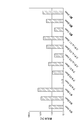
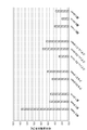
- FIG. 7 is a diagram showing an example of the scattering rate of 662 keV radiation in the various shield members 3 of FIGS. As shown in FIG. 7, it can be seen that the scattering rate increases as the thickness of the shield member 3 increases. Moreover, as a kind of the shield member 3, it turns out that Au has the highest scattering rate among Au, Al, stainless steel, and Cu.
- FIG. 8 is a diagram showing the rate of increase in the amount of radiation absorbed in the radiation detector 2.
- the increase rate of the radiation absorption amount is an increase rate with respect to the radiation absorption amount in the radiation detector 2 when the shield member 3 is not provided.
- the increase rate of the radiation absorption amount is the highest and is 13.6%. is there. Even when other types of shield members 3 are used, an increase rate of about several percent can be obtained.
- the increase rate of the radiation absorption amount is determined by the ratio between the radiation scattering rate by the shield member 3 and the radiation absorption rate by the radiation detector 2. For this reason, by using the shield member 3 having a high scattering rate and the radiation detector 2 having a high absorption rate in a low energy region, the rate of increase in the amount of radiation absorption in the radiation detector 2 is also increased.
- the energy distribution ratio near 662 keV is close to 100%, and the energy distribution ratio below 660 keV is about several percent.
- the scattering itself in the shield member 3 is only about several percent, but the energy of the radiation r2 after the scattering is , Distributed at a constant rate in an energy region lower than 662 keV.
- the absorption rate of 662 keV energy of the radiation detector 2 is about 0.7%, but the absorption rate of energy of 200 keV is about 3%, and the absorption rate of energy of 100 keV is 15%. %.
- the absorption rate of the low-energy radiation r2 after scattering is higher than the absorption rate of the radiation r1 before scattering.
- Absorption rate (detection sensitivity) is improved by about 10%.
- the radiation r2 scattered by the shield member 3 is detected by the radiation detector 2.
- the radiation absorption rate in the radiation detector 2 is improved, and the radiation detection sensitivity is improved.
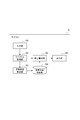
- FIG. 9 is a functional block diagram of the microcomputer 5. As shown in FIG. 9, the microcomputer 5 includes an input unit 51, a spectrum acquisition unit 52, a conversion coefficient calculation unit 53, a conversion coefficient storage unit 54, a dose calculation unit 55, and an output unit 56. ing.
- the input unit 51 accepts a user operation via the operation button 6. Then, the input unit 51 determines the content of the accepted operation. For example, the input unit 51 determines whether the received operation is an operation for selecting the initialization mode. For example, the input unit 51 determines whether or not an operation for selecting an initialization mode is performed when an operation mode selection screen is displayed on the display device 7. Then, the input unit 51 transmits operation information regarding the received operation to the spectrum acquisition unit 52 and the dose calculation unit 55. For example, the input unit 51 transmits information on the selected operation mode to the spectrum acquisition unit 52 and the dose calculation unit 55.
- the spectrum acquisition unit 52 acquires the channel spectrum of the radiation detected by the radiation detector 2. For example, the spectrum acquisition unit 52 receives the detection signal output from the amplifier 4 in response to receiving information about the operation mode from the input unit 51. And the spectrum acquisition part 52 acquires the channel spectrum by measuring the voltage value of the received detection signal and counting the number of incidents in a histogram format with the voltage value (channel) as the horizontal axis.
- the conversion coefficient calculation unit 53 calculates a conversion coefficient for converting energy into a dose based on the channel spectrum acquired by the spectrum acquisition unit 52.
- a method for calculating the conversion coefficient from the channel spectrum will be specifically described below.
- the conversion coefficient calculation unit 53 analyzes the channel spectrum acquired by the spectrum acquisition unit 52 and searches for the peak of the channel spectrum. Then, the conversion coefficient calculation unit 53 calculates the peak centroid channel.
- the peak center-of-gravity channel Ch p is a channel corresponding to the center point of the peak, and is calculated by the following equation (1) using the total sum S all of the weighted areas and the total count value C all .
- the sum S all of the weighted area, in end channel Ch b peaks from start channel Ch a peak, the count value C i and the channel Ch of each channel Ch i Calculated by the sum of products with i .
- the peak generally follows a Gaussian distribution.
- the peak start channel Ch a and the end channel Ch b are determined by an eye measurement manual or automatic acquisition algorithm as a point where the entire Gaussian distribution enters.
- a and b are integers of 1 or more, and b is larger than a.
- the total count value C all is calculated by the sum of the count values C i of each channel Ch i from the peak start channel Ch a to the peak end channel Ch b .
- the conversion coefficient calculation unit 53 calculates a first calibration coefficient A and a second calibration coefficient B for converting the channel Ch into energy E.
- the first peak centroid channel Ch p1 the relationship between the first energy E 1 predetermined by using a first calibration factor A and a second calibration coefficient B is represented by the following formula (4)
- the relationship between the second peak centroid channel Ch p2 and the predetermined second energy E 2 is expressed by the following equation (5) using the first calibration coefficient A and the second calibration coefficient B.
- the first energy E 1 and the second energy E 2 are peak energies of radioactive materials whose peak energy in the energy spectrum is known in advance.
- the first peak centroid channel Ch p1 is the channel spectrum of a radioactive substance having a first peak energy of the energy E 1 was measured, the peak centroid channel calculated from measured channel spectrum.
- the second peak centroid channel Ch p2 is the channel spectrum of a radioactive substance having a second energy peak energy of E 2 was measured, the peak centroid channel calculated from measured channel spectrum.
- the first calibration coefficient A and the second calibration coefficient B are calculated by the following expressions (6) and (7) obtained by solving the simultaneous equations (4) and (5).
- the conversion coefficient calculation unit 53 stores the first calibration coefficient A and the second calibration coefficient B in the conversion coefficient storage unit 54.
- the conversion coefficient calculation unit 53 converts the channel Ch into energy E.
- the energy E j is calculated by the following equation (8) using the channel Ch j , the first calibration coefficient A, and the second calibration coefficient B.
- the conversion coefficient calculation unit 53 converts the channel spectrum acquired by the spectrum acquisition unit 52 into a histogram (energy spectrum) of energy E versus count value C by converting each channel Ch j into energy E j. . Furthermore, the conversion coefficient calculation unit 53 adds the count values for each constant energy range (for example, 100 keV) in the energy spectrum, and converts the energy spectrum into a spectrum of ten or more points.
- the conversion coefficient calculation part 53 calculates a conversion coefficient for every energy range by integrating
- the survey meter coefficient is a response function of a survey meter corresponding to the energy of radiation, and is disclosed by survey meter vendors. This survey meter coefficient is predetermined for each energy. Further, the conversion coefficient calculation unit 53 stores the calculated conversion coefficient in the conversion coefficient storage unit 54.
- the conversion coefficient storage unit 54 stores the first calibration coefficient A and the second calibration coefficient B calculated by the conversion coefficient calculation unit 53, and the conversion coefficient for each energy calculated by the conversion coefficient calculation unit 53.
- the dose calculation unit 55 calculates a dose based on the channel spectrum acquired by the spectrum acquisition unit 52, the first calibration coefficient A and the second calibration coefficient B stored in the conversion coefficient storage unit 54, and the conversion coefficient. . More specifically, the dose calculation unit 55 converts the channel spectrum into an energy spectrum using the first calibration coefficient A and the second calibration coefficient B as shown in the above equation (8). Furthermore, the dose calculation unit 55 adds the energy spectrum count values for each energy range that is the same as the conversion coefficient, and converts the energy spectrum into a spectrum of dozens of points.
- the dose calculation unit 55 calculates the dose for each energy range by integrating the count value of each energy range and the conversion coefficient corresponding to the energy range. And the dose calculation part 55 calculates the whole dose by adding the dose for every energy range.
- the output unit 56 outputs display information for displaying the dose calculated by the dose calculation unit 55 to the display device 7.
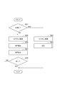
- FIG. 10 is a flowchart showing the operation of the radiation dosimeter 1.
- the operation of the radiation dosimeter 1 is started when the power switch 9 is operated by the user and the power supply 8 is turned on from the off state.
- the input unit 51 determines whether or not the accepted operation is an operation for selecting an initialization mode (step S01). If it is determined in step S01 that the operation is to select an initialization mode (step S01; YES), an initialization process is performed.
- the spectrum acquisition unit 52 receives the detection signal output from the radiation detector 2 via the amplifier 4, and acquires the channel spectrum of the radiation detected by the radiation detector 2 (step S02). .
- the conversion coefficient calculation unit 53 calculates a conversion coefficient based on the channel spectrum acquired by the spectrum acquisition unit 52, and stores the calculated conversion coefficient in the conversion coefficient storage unit 54 (step S03). Details of step S03 will be described later.
- the operation (initialization process) of the radiation dosimeter 1 ends.
- step S01 when it is determined in step S01 that the operation is not an operation for selecting the initialization mode (step S01; NO), that is, when it is determined that the operation is for selecting another operation mode, radiation corresponding to the selected mode is selected.
- a dose calculation process is performed.
- the spectrum acquisition unit 52 receives the detection signal output from the radiation detector 2 via the amplifier 4 and acquires the channel spectrum of the radiation detected by the radiation detector 2 (step). S05).
- the dose calculation unit 55 is acquired by the spectrum acquisition unit 52 based on the first calibration coefficient A and the second calibration coefficient B stored in the conversion coefficient storage unit 54 using the above-described equation (8).
- the obtained channel spectrum is converted into an energy spectrum (spectrum acquisition step).
- the dose calculation unit 55 calculates the dose of radiation based on the converted energy spectrum and the conversion coefficient stored in the conversion coefficient storage unit 54 (step S06, dose calculation step). That is, the dose calculation unit 55 calculates the dose for each energy by integrating the count value of each energy in the energy spectrum and the conversion coefficient corresponding to the energy. And the dose calculation part 55 calculates the whole dose by adding the dose for every energy.
- step S08 the input unit 51 determines whether or not an operation for ending the radiation dose calculation process has been performed.
- the operation for ending the radiation dose calculation process is, for example, an operation for turning off the power supply 8 by the power switch 9. If it is determined in step S08 that the operation for ending the radiation dose calculation process has not been performed (step S08; NO), the process returns to step S05, and the processes in steps S05 to S08 are repeated.
- step S08 when it is determined in step S08 that an operation for ending the radiation dose calculation process has been performed (step S08; YES), the operation of the radiation dosimeter 1 (radiation dose calculation process) is ended.
- step S08 is provided after step S07.
- step S08 is set in advance regardless of the flowchart of FIG. It may be performed every period.
- FIG. 11 is a flowchart showing details of the calibration process.
- the conversion coefficient calculation unit 53 analyzes the channel spectrum acquired by the spectrum acquisition unit 52 and searches for the peak of the channel spectrum (step S31). Then, the conversion coefficient calculation unit 53 calculates the peak centroid channel using the above equations (1) to (3) (step S32).
- the conversion coefficient calculation unit 53 uses the above-described equations (4) to (7) to calculate the first calibration coefficient A and the second calibration value for converting the channel into energy based on the calculated peak centroid channel.
- a calibration coefficient B is calculated.
- the conversion factor calculation part 53 converts a channel spectrum into an energy spectrum using the above-mentioned formula (8) (Step S33).
- the conversion coefficient calculation unit 53 adds the count values for each constant energy range (for example, 100 keV) in the energy spectrum, and converts the energy spectrum into a spectrum of dozens of points. And the conversion factor calculation part 53 calculates the conversion factor for every energy range by integrating
- the conversion coefficient calculation unit 53 stores the calculated conversion coefficient in the conversion coefficient storage unit 54 (step S35), and ends the calibration process.
- the radiation dosimeter 1 and the radiation dose calculation method using the radiation dosimeter 1 described above by covering the radiation detector 2 with the shield member 3, noise can be reduced and the incident radiation r1 can be scattered. be able to.
- the energy of the radiation r2 after the scattering is distributed at a constant rate in an energy region lower than the energy of the radiation r1 before the scattering.
- the radiation detector 2 has a higher radiation absorptance in an energy region lower than the energy of the radiation r1 before scattering than the radiation absorptance in the energy of the radiation r1 before scattering. For this reason, the detection sensitivity of radiation can be improved.
- the dose in the absence of the shield member 3, that is, directly to the human body is calculated using a conversion coefficient determined according to the energy of the radiation scattered by the shield member 3, the dose in the absence of the shield member 3, that is, directly to the human body. It is possible to calculate the net dose absorbed. As a result, dose measurement accuracy can be improved without complicating the structure.
- the radiation dosimeter and the radiation dose calculation method according to the present invention are not limited to those described in this embodiment.
- the radiation detector 2 only needs to have an absorption rate in an energy region lower than the energy before scattering of radiation to be detected higher than the absorption rate in energy before scattering of radiation, CdZnTe (cadmium zinc telluride), You may be comprised from TlBr (thallium bromide), Ge (germanium), etc.
- the input unit 51 determines that the initialization mode has been selected by detecting that the power switch 9 is pressed and the power supply 8 is turned on while the predetermined operation button 6 is pressed. May be.
- the conversion coefficient calculation part 53 is calculating the conversion coefficient for every 100 keV, you may calculate a conversion coefficient for every arbitrary energy range. By further reducing the energy range, the dose calculation unit 55 can calculate a more accurate dose.
- the conversion coefficient calculation unit 53 may calculate a second conversion coefficient for converting the count value for each channel into a dose based on the first calibration coefficient A, the second calibration coefficient B, and the conversion coefficient.
- the dose calculation unit 55 may calculate the dose by adding the second conversion coefficient to the count value for each channel of the channel spectrum acquired by the spectrum acquisition unit 52.
Landscapes
- Physics & Mathematics (AREA)
- Health & Medical Sciences (AREA)
- Life Sciences & Earth Sciences (AREA)
- General Physics & Mathematics (AREA)
- High Energy & Nuclear Physics (AREA)
- Molecular Biology (AREA)
- Spectroscopy & Molecular Physics (AREA)
- Measurement Of Radiation (AREA)
Description








Claims (6)
- 放射線を検出するための放射線検出体と、
前記放射線検出体を覆うシールド部材と、
前記放射線検出体によって検出された放射線のエネルギーと、前記シールド部材によって散乱された放射線のエネルギーに応じて定められる変換係数と、に基づいて放射線の線量を算出する演算装置と、
を備え、
前記放射線検出体は、前記シールド部材によって散乱された放射線を検出する、放射線線量計。 - 前記放射線検出体は、CdTeから構成される、請求項1に記載の放射線線量計。
- 前記シールド部材は、Au、Cu、Alおよびステンレス鋼のいずれかから構成される、請求項1または請求項2に記載の放射線線量計。
- 前記シールド部材は、0.1mm以上1.0mm以下の厚さを有する、請求項1~請求項3のいずれか一項に記載の放射線線量計。
- 前記演算装置によって算出された線量を表示する表示装置をさらに備える、請求項1~請求項4のいずれか一項に記載の放射線線量計。
- シールド部材に覆われた放射線検出体を備える放射線線量計における放射線線量の算出方法であって、
前記シールド部材によって散乱された後に前記放射線検出体によって検出された放射線のエネルギースペクトルを取得するスペクトル取得ステップと、
前記スペクトル取得ステップにおいて取得された前記エネルギースペクトルと、前記シールド部材によって散乱された放射線のエネルギーに応じて定められる変換係数と、に基づいて前記放射線線量を算出する線量算出ステップと、
を備える、放射線線量の算出方法。
Priority Applications (5)
| Application Number | Priority Date | Filing Date | Title |
|---|---|---|---|
| JP2014519906A JP6241888B2 (ja) | 2012-06-07 | 2013-05-20 | 放射線線量計および放射線線量の算出方法 |
| US14/405,905 US20150153461A1 (en) | 2012-06-07 | 2013-05-20 | Radiation dosimeter and radiation dose calculation method |
| CN201380029905.5A CN104335071B (zh) | 2012-06-07 | 2013-05-20 | 放射线剂量计及放射线剂量的计算方法 |
| EP13800595.4A EP2860552B1 (en) | 2012-06-07 | 2013-05-20 | Radiation dosimeter and radiation dose calculation method |
| IN10855DEN2014 IN2014DN10855A (ja) | 2012-06-07 | 2013-05-20 |
Applications Claiming Priority (2)
| Application Number | Priority Date | Filing Date | Title |
|---|---|---|---|
| JP2012129788 | 2012-06-07 | ||
| JP2012-129788 | 2012-06-07 |
Publications (1)
| Publication Number | Publication Date |
|---|---|
| WO2013183434A1 true WO2013183434A1 (ja) | 2013-12-12 |
Family
ID=49711832
Family Applications (1)
| Application Number | Title | Priority Date | Filing Date |
|---|---|---|---|
| PCT/JP2013/063961 Ceased WO2013183434A1 (ja) | 2012-06-07 | 2013-05-20 | 放射線線量計および放射線線量の算出方法 |
Country Status (6)
| Country | Link |
|---|---|
| US (1) | US20150153461A1 (ja) |
| EP (1) | EP2860552B1 (ja) |
| JP (1) | JP6241888B2 (ja) |
| CN (1) | CN104335071B (ja) |
| IN (1) | IN2014DN10855A (ja) |
| WO (1) | WO2013183434A1 (ja) |
Families Citing this family (6)
| Publication number | Priority date | Publication date | Assignee | Title |
|---|---|---|---|---|
| US9841508B2 (en) * | 2014-08-26 | 2017-12-12 | Mitsubishi Electric Corporation | Dose rate measuring device |
| JP6184608B2 (ja) * | 2014-10-23 | 2017-08-23 | 三菱電機株式会社 | 線量率測定装置 |
| CN108324295B (zh) * | 2017-12-18 | 2021-03-23 | 江苏赛诺格兰医疗科技有限公司 | 能谱寻峰方法、装置和计算机存储介质 |
| US10575196B2 (en) * | 2018-04-04 | 2020-02-25 | Rohde & Schwarz Gmbh & Co. Kg | Measurement system and method for testing a device under test |
| US10809290B2 (en) * | 2018-07-31 | 2020-10-20 | Rohde & Schwarz Gmbh & Co. Kg | Resonant cavity for wireless communication measurement and corresponding method |
| CN119882000A (zh) * | 2025-02-26 | 2025-04-25 | 华中科技大学鄂州工业技术研究院 | 一种剂量仪电路 |
Citations (5)
| Publication number | Priority date | Publication date | Assignee | Title |
|---|---|---|---|---|
| JPS63271187A (ja) * | 1987-04-28 | 1988-11-09 | Matsushita Electric Ind Co Ltd | 線量測定器 |
| JPH0420893A (ja) * | 1990-05-16 | 1992-01-24 | Aloka Co Ltd | 携帯用中性子線量当量計 |
| JP2001004754A (ja) | 1999-06-22 | 2001-01-12 | Mitsubishi Electric Corp | 放射線検出器および放射線検出器の試験方法 |
| JP2001221860A (ja) * | 1999-11-29 | 2001-08-17 | Mitsubishi Electric Corp | 放射線施設の線量当量評価方法、線量当量を評価するコンピュータプログラムを記録した記録媒体および線量当量評価装置 |
| WO2009062639A2 (de) * | 2007-11-15 | 2009-05-22 | Gsi Helmholtzzentrum Für Schwerionenforschung Gmbh | Ortsdosimeter zur messung der umgebungsäquivalentdosis von photonenstrahlung und verfahren zum auslesen |
Family Cites Families (12)
| Publication number | Priority date | Publication date | Assignee | Title |
|---|---|---|---|---|
| US3122640A (en) * | 1960-05-13 | 1964-02-25 | Preston V Murphy | Method and apparatus for measuring the dosage of x-rays and gamma rays |
| US4461952A (en) * | 1980-10-24 | 1984-07-24 | Commissariat A L'energie Atomique | Portable computing device for measuring radiations |
| JPS5999276A (ja) * | 1982-11-27 | 1984-06-07 | Hitachi Ltd | 放射能測定方法及び装置 |
| US4859853A (en) * | 1988-02-04 | 1989-08-22 | The United States Of America As Represented By The Secretary Of The Army | Solid state gamma ray dosimeter which measures radiation in terms of absorption in a material different from the detector material |
| US4893017A (en) * | 1988-10-14 | 1990-01-09 | The United State Of America As Represented By The Sectretay Of The Army | Dose and dose rate sensor for the pocket radiac |
| US5567944A (en) * | 1995-04-28 | 1996-10-22 | University Of Cincinnati | Compton camera for in vivo medical imaging of radiopharmaceuticals |
| WO2004027453A1 (en) * | 2002-09-18 | 2004-04-01 | Koninklijke Philips Electronics N.V. | Radiation detector |
| DE102006006411A1 (de) * | 2006-02-09 | 2007-08-16 | Friedrich-Alexander-Universität Erlangen-Nürnberg | Anordnungen und Verfahren zur Bestimmung von Dosismessgrößen und zur Ermittlung von Energieinformation einfallender Strahlung aus Photonen oder geladenen Teilchen mit zählenden Detektoreinheiten |
| WO2009043347A1 (en) * | 2007-10-04 | 2009-04-09 | Danmarks Tekniske Universitet | A detector for detecting particle radiation of an energy in the range of 150 ev to 300 kev, and a materials mapping apparatus with such a detector. |
| JP2010085259A (ja) * | 2008-09-30 | 2010-04-15 | Fujifilm Corp | 放射線検出装置及び放射線撮影システム |
| US8183535B2 (en) * | 2009-02-11 | 2012-05-22 | Mats Danielsson | Silicon detector assembly for X-ray imaging |
| US8515011B2 (en) * | 2009-06-02 | 2013-08-20 | Mayo Foundation For Medical Education And Research | System and method for dose verification radiotherapy |
-
2013
- 2013-05-20 CN CN201380029905.5A patent/CN104335071B/zh active Active
- 2013-05-20 WO PCT/JP2013/063961 patent/WO2013183434A1/ja not_active Ceased
- 2013-05-20 JP JP2014519906A patent/JP6241888B2/ja active Active
- 2013-05-20 US US14/405,905 patent/US20150153461A1/en not_active Abandoned
- 2013-05-20 EP EP13800595.4A patent/EP2860552B1/en active Active
- 2013-05-20 IN IN10855DEN2014 patent/IN2014DN10855A/en unknown
Patent Citations (5)
| Publication number | Priority date | Publication date | Assignee | Title |
|---|---|---|---|---|
| JPS63271187A (ja) * | 1987-04-28 | 1988-11-09 | Matsushita Electric Ind Co Ltd | 線量測定器 |
| JPH0420893A (ja) * | 1990-05-16 | 1992-01-24 | Aloka Co Ltd | 携帯用中性子線量当量計 |
| JP2001004754A (ja) | 1999-06-22 | 2001-01-12 | Mitsubishi Electric Corp | 放射線検出器および放射線検出器の試験方法 |
| JP2001221860A (ja) * | 1999-11-29 | 2001-08-17 | Mitsubishi Electric Corp | 放射線施設の線量当量評価方法、線量当量を評価するコンピュータプログラムを記録した記録媒体および線量当量評価装置 |
| WO2009062639A2 (de) * | 2007-11-15 | 2009-05-22 | Gsi Helmholtzzentrum Für Schwerionenforschung Gmbh | Ortsdosimeter zur messung der umgebungsäquivalentdosis von photonenstrahlung und verfahren zum auslesen |
Also Published As
| Publication number | Publication date |
|---|---|
| CN104335071A (zh) | 2015-02-04 |
| US20150153461A1 (en) | 2015-06-04 |
| JPWO2013183434A1 (ja) | 2016-01-28 |
| EP2860552B1 (en) | 2020-09-23 |
| IN2014DN10855A (ja) | 2015-09-11 |
| EP2860552A4 (en) | 2016-02-24 |
| EP2860552A1 (en) | 2015-04-15 |
| JP6241888B2 (ja) | 2017-12-06 |
| CN104335071B (zh) | 2016-09-28 |
Similar Documents
| Publication | Publication Date | Title |
|---|---|---|
| JP6241888B2 (ja) | 放射線線量計および放射線線量の算出方法 | |
| Ren et al. | Tutorial on X-ray photon counting detector characterization | |
| EP1917541B1 (en) | Combined radiation dosimeter and rate meter | |
| CN103069305B (zh) | 由多能量x-射线识别材料的方法 | |
| EP2896973B1 (en) | Radioactivity analysis device | |
| JP6257916B2 (ja) | 光検出装置、放射線検出装置、放射線分析装置及び光検出方法 | |
| JP2015501928A (ja) | 検出器装置及び検出方法 | |
| JP2008256630A (ja) | エネルギー補償型シンチレーション式光子線量計 | |
| JPH07128451A (ja) | 物体の放射能汚染を測定する装置 | |
| US20140254757A1 (en) | X-ray imaging apparatus and control method for the same | |
| US11079222B2 (en) | Radiation-based thickness gauge | |
| US8927939B2 (en) | Radiation measurement apparatus and nuclear medicine diagnosis apparatus | |
| JP2022184295A (ja) | データ処理装置、データ処理方法およびデータ処理プログラム | |
| Damulira et al. | Application of Bpw34 photodiode and cold white LED as diagnostic X-ray detectors: A comparative analysis | |
| JPWO2018116584A1 (ja) | 放射能分布測定装置及び方法 | |
| JP3824211B2 (ja) | 放射線モニタ装置 | |
| Fernandes et al. | Application of large‐area avalanche photodiodes to energy‐dispersive x‐ray fluorescence analysis | |
| US20180333119A1 (en) | Image processing apparatus, radiography system, image processing method, and image processing program | |
| EP3444638A1 (en) | Indirect photon-counting analytical x-ray detector | |
| JP5693139B2 (ja) | 放射線検出装置 | |
| JP2007248319A (ja) | シンチレーション検出器およびシンチレーション式低エネルギー光子1cm線量当量計 | |
| Rao et al. | An alpha tagged X-ray source for the calibration of space borne X-ray detectors | |
| EP4549875A1 (en) | Thickness measuring method, x-ray analysis device, information processing device, and computer program | |
| WO2024128301A1 (ja) | 信号処理方法、信号処理装置、放射線検出装置、及びコンピュータプログラム | |
| WO2013076506A2 (en) | Portable detector apparatus |
Legal Events
| Date | Code | Title | Description |
|---|---|---|---|
| 121 | Ep: the epo has been informed by wipo that ep was designated in this application |
Ref document number: 13800595 Country of ref document: EP Kind code of ref document: A1 |
|
| ENP | Entry into the national phase |
Ref document number: 2014519906 Country of ref document: JP Kind code of ref document: A |
|
| WWE | Wipo information: entry into national phase |
Ref document number: 14405905 Country of ref document: US |
|
| NENP | Non-entry into the national phase |
Ref country code: DE |
|
| WWE | Wipo information: entry into national phase |
Ref document number: 2013800595 Country of ref document: EP |