WO2013183480A1 - 充電率推定方法及び充電率推定装置 - Google Patents
充電率推定方法及び充電率推定装置 Download PDFInfo
- Publication number
- WO2013183480A1 WO2013183480A1 PCT/JP2013/064625 JP2013064625W WO2013183480A1 WO 2013183480 A1 WO2013183480 A1 WO 2013183480A1 JP 2013064625 W JP2013064625 W JP 2013064625W WO 2013183480 A1 WO2013183480 A1 WO 2013183480A1
- Authority
- WO
- WIPO (PCT)
- Prior art keywords
- open circuit
- secondary battery
- charging
- circuit voltage
- voltage
- Prior art date
- Legal status (The legal status is an assumption and is not a legal conclusion. Google has not performed a legal analysis and makes no representation as to the accuracy of the status listed.)
- Ceased
Links
Images



Classifications
-
- G—PHYSICS
- G01—MEASURING; TESTING
- G01R—MEASURING ELECTRIC VARIABLES; MEASURING MAGNETIC VARIABLES
- G01R31/00—Arrangements for testing electric properties; Arrangements for locating electric faults; Arrangements for electrical testing characterised by what is being tested not provided for elsewhere
- G01R31/36—Arrangements for testing, measuring or monitoring the electrical condition of accumulators or electric batteries, e.g. capacity or state of charge [SoC]
- G01R31/3644—Constructional arrangements
- G01R31/3648—Constructional arrangements comprising digital calculation means, e.g. for performing an algorithm
-
- G—PHYSICS
- G01—MEASURING; TESTING
- G01R—MEASURING ELECTRIC VARIABLES; MEASURING MAGNETIC VARIABLES
- G01R31/00—Arrangements for testing electric properties; Arrangements for locating electric faults; Arrangements for electrical testing characterised by what is being tested not provided for elsewhere
- G01R31/36—Arrangements for testing, measuring or monitoring the electrical condition of accumulators or electric batteries, e.g. capacity or state of charge [SoC]
- G01R31/367—Software therefor, e.g. for battery testing using modelling or look-up tables
-
- G—PHYSICS
- G01—MEASURING; TESTING
- G01R—MEASURING ELECTRIC VARIABLES; MEASURING MAGNETIC VARIABLES
- G01R31/00—Arrangements for testing electric properties; Arrangements for locating electric faults; Arrangements for electrical testing characterised by what is being tested not provided for elsewhere
- G01R31/36—Arrangements for testing, measuring or monitoring the electrical condition of accumulators or electric batteries, e.g. capacity or state of charge [SoC]
- G01R31/382—Arrangements for monitoring battery or accumulator variables, e.g. SoC
-
- G—PHYSICS
- G01—MEASURING; TESTING
- G01R—MEASURING ELECTRIC VARIABLES; MEASURING MAGNETIC VARIABLES
- G01R31/00—Arrangements for testing electric properties; Arrangements for locating electric faults; Arrangements for electrical testing characterised by what is being tested not provided for elsewhere
- G01R31/36—Arrangements for testing, measuring or monitoring the electrical condition of accumulators or electric batteries, e.g. capacity or state of charge [SoC]
- G01R31/382—Arrangements for monitoring battery or accumulator variables, e.g. SoC
- G01R31/3835—Arrangements for monitoring battery or accumulator variables, e.g. SoC involving only voltage measurements
-
- H—ELECTRICITY
- H01—ELECTRIC ELEMENTS
- H01M—PROCESSES OR MEANS, e.g. BATTERIES, FOR THE DIRECT CONVERSION OF CHEMICAL ENERGY INTO ELECTRICAL ENERGY
- H01M10/00—Secondary cells; Manufacture thereof
- H01M10/42—Methods or arrangements for servicing or maintenance of secondary cells or secondary half-cells
- H01M10/48—Accumulators combined with arrangements for measuring, testing or indicating the condition of cells, e.g. the level or density of the electrolyte
-
- H—ELECTRICITY
- H01—ELECTRIC ELEMENTS
- H01M—PROCESSES OR MEANS, e.g. BATTERIES, FOR THE DIRECT CONVERSION OF CHEMICAL ENERGY INTO ELECTRICAL ENERGY
- H01M10/00—Secondary cells; Manufacture thereof
- H01M10/42—Methods or arrangements for servicing or maintenance of secondary cells or secondary half-cells
- H01M10/48—Accumulators combined with arrangements for measuring, testing or indicating the condition of cells, e.g. the level or density of the electrolyte
- H01M10/486—Accumulators combined with arrangements for measuring, testing or indicating the condition of cells, e.g. the level or density of the electrolyte for measuring temperature
-
- H—ELECTRICITY
- H02—GENERATION; CONVERSION OR DISTRIBUTION OF ELECTRIC POWER
- H02J—ELECTRIC POWER NETWORKS; CIRCUIT ARRANGEMENTS OR SYSTEMS FOR SUPPLYING OR DISTRIBUTING ELECTRIC POWER; SYSTEMS FOR STORING ELECTRIC ENERGY
- H02J7/00—Circuit arrangements for charging or discharging batteries or for supplying loads from batteries
- H02J7/80—Circuit arrangements for charging or discharging batteries or for supplying loads from batteries including monitoring or indicating arrangements
- H02J7/82—Control of state of charge [SOC]
- H02J7/825—Detection of fully charged condition
-
- Y—GENERAL TAGGING OF NEW TECHNOLOGICAL DEVELOPMENTS; GENERAL TAGGING OF CROSS-SECTIONAL TECHNOLOGIES SPANNING OVER SEVERAL SECTIONS OF THE IPC; TECHNICAL SUBJECTS COVERED BY FORMER USPC CROSS-REFERENCE ART COLLECTIONS [XRACs] AND DIGESTS
- Y02—TECHNOLOGIES OR APPLICATIONS FOR MITIGATION OR ADAPTATION AGAINST CLIMATE CHANGE
- Y02E—REDUCTION OF GREENHOUSE GAS [GHG] EMISSIONS, RELATED TO ENERGY GENERATION, TRANSMISSION OR DISTRIBUTION
- Y02E60/00—Enabling technologies; Technologies with a potential or indirect contribution to GHG emissions mitigation
- Y02E60/10—Energy storage using batteries
Definitions
- the present invention relates to a charging rate estimation method and a charging rate estimation device for estimating a charging rate of a secondary battery.
- the charging rate estimation method disclosed in Patent Document 1 below can be cited. That is, in the conventional method, the time variation of the open circuit voltage of the secondary battery after the completion of charging / discharging is approximated by a voltage characteristic equation, and the open circuit voltage at the time of stabilization of the secondary battery is calculated from the voltage characteristic equation to calculate the secondary battery.
- the charging rate is estimated. Specifically, the open circuit voltage of the secondary battery is measured a plurality of times during a predetermined data acquisition period after the end of charge / discharge. Then, by applying these measured open circuit voltages to the voltage characteristic equation, the parameters included in the voltage characteristic equation are obtained, and the open circuit voltage at the time of stability is calculated.
- the present inventors examined the charge / discharge characteristics of various secondary batteries, and found that the charge / discharge characteristics estimated at the end of charge / discharge were estimated based on the integrated current value or the estimated open circuit voltage obtained using the closed circuit voltage.
- the voltage change convergence time ⁇ from the end of charging / discharging of the secondary battery to the convergence of the open circuit voltage change is It was found that a constant value was taken.
- the conventional method uses only the measured open circuit voltage applied to the voltage characteristic equation, and the voltage change convergence time ⁇ takes a constant value for each combination of the charging rate and temperature of the secondary battery at the end of charging and discharging. As a result, more open circuit voltage measurements are required and the time required to estimate the charge rate is longer.
- the estimated open circuit voltage obtained using the closed circuit voltage is an open circuit voltage estimated based on the closed circuit voltage or current.
- the present invention has been made to solve the above-described problems, and its purpose is to estimate the charging rate with a smaller number of measured open circuit voltages and to reduce the time required for estimating the charging rate.
- a charge rate estimation method and a charge rate estimation device that can be used.
- the charging rate estimation method approximates the time change of the open circuit voltage of the secondary battery after the end of charging / discharging with a voltage characteristic equation, and calculates the open circuit voltage at the time of stabilization of the secondary battery from the voltage characteristic equation.
- the voltage change convergence time ⁇ from the end of charge / discharge until the change in open circuit voltage converges is measured in advance and the charge / discharge of the secondary battery is completed, the charge rate at the end of charge / discharge Then, the voltage change convergence time ⁇ corresponding to the temperature is selected, and the selected voltage change convergence time ⁇ is applied to the voltage characteristic equation.
- the charging rate estimation device calculates the secondary circuit voltage when the secondary battery is stable from the voltage characteristic equation that approximates the time change of the open circuit voltage of the secondary battery after the end of charging and discharging.
- Storage unit for storing the voltage change convergence time ⁇ from when the open circuit voltage is converged to when the open circuit voltage converges, and when the charge / discharge of the secondary battery is completed, the charge rate and temperature at the end of charge / discharge are A corresponding voltage change convergence time ⁇ is selected from the storage unit, and a calculation unit that applies the selected voltage change convergence time ⁇ to the voltage characteristic equation is provided.
- the charging of the secondary battery is performed for each combination of the charging rate of the secondary battery at the end of charge / discharge and the temperature of the secondary battery at the end of charge / discharge.
- the voltage change convergence time ⁇ from the end of discharge until the change in open circuit voltage converges is measured in advance, and the charge / discharge of the secondary battery is completed, the charge rate and temperature at the end of charge / discharge Since the voltage change convergence time ⁇ corresponding to is selected and the selected voltage change convergence time ⁇ is applied to the voltage characteristic equation, the charge rate can be estimated with a smaller number of measured open circuit voltages, and the charge rate can be estimated. The time required can be shortened.
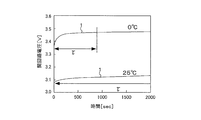
- FIG. FIG. 1 is an explanatory diagram showing a change in the open circuit voltage of the secondary battery after the end of charging
- FIG. 2 is an explanatory diagram showing a change in the open circuit voltage of the secondary battery after the end of discharging.
- the open circuit voltage 1 of the secondary battery after the end of charge / discharge converges to a constant value after a predetermined time has elapsed from the end of charge / discharge.
- the time from the end of charge / discharge of the secondary battery to the convergence of the change in the open circuit voltage 1 is referred to as a voltage change convergence time ⁇ .
- the change in the open circuit voltage 1 converges means that a state which can be regarded as the change per unit of time the open circuit voltage 1 (dV OCV / dt) is equal to zero.
- the voltage change convergence time ⁇ at the end of charging and the voltage change convergence time ⁇ at the end of discharging are different from each other.
- the voltage change convergence time ⁇ varies according to the temperature of the secondary battery at the end of charge / discharge, as shown in FIGS. I found out that Although not shown, the voltage change convergence time ⁇ is estimated at the end of charging / discharging estimated based on an integrated current value or an estimated open circuit voltage (hereinafter referred to as an integrated current value) obtained using a closed circuit voltage. It was also found that it depends on the charging rate of the secondary battery. In addition, a charging rate can be estimated by calculating
- the time variation of the open circuit voltage 1 of the secondary battery after the end of charging / discharging is approximated by a voltage characteristic equation, and the open circuit voltage 1 at the time of stabilization of the secondary battery is calculated from this voltage characteristic equation. From the above, it is known that the charging rate of the secondary battery can be estimated. The present inventors have found that the charging rate can be estimated with a smaller number of measured values of open circuit voltage by applying the voltage change convergence time ⁇ as described above to the voltage characteristic equation.
- the charging rate estimation method in which the voltage change convergence time ⁇ is applied to the voltage characteristic equation will be described more specifically.
- FIG. 3 is an explanatory diagram showing a map including a plurality of voltage change convergence times ⁇ measured in advance based on the charging rate estimation method of the present embodiment.
- the voltage change convergence time ⁇ depends on the charge rate of the secondary battery at the end of charge / discharge estimated based on the integrated current value and the like, and the temperature of the secondary battery at the end of charge / discharge.
- the change convergence time ⁇ 1-1... XY is experimentally measured in advance and a map as shown in FIG. 3 is created.
- FIG. 4 is a flowchart showing a charging rate estimation method after the map of FIG. 3 is created.
- the open circuit voltage 1 of the secondary battery is measured at the end of charging / discharging (step S1), and the charging of the secondary battery based on the integrated current value at the end of charging / discharging is performed.
- the voltage change convergence time ⁇ corresponding to the rate and temperature is selected from the map (step S2).
- the open circuit voltage 1 of the secondary battery after the completion of charge / discharge is measured at least once at a predetermined measurement interval of, for example, several milliseconds to several seconds (step S3).
- the open circuit voltage 1 at the time of stabilization of the secondary battery is calculated from the voltage characteristic equation (step S4), and the calculated open circuit voltage
- the charging rate of the secondary battery is estimated from 1 (step S5).
- V OCV (t) A 1 exp ( ⁇ B 1 t) +... + A n + 1 exp ( ⁇ B n + 1 t) + V C (1)
- t is an elapsed time from the end of charging / discharging
- n is the number of measurements of the open circuit voltage 1 after the end of charging / discharging
- V C is a parameter constituting the voltage characteristic equation. Note that the term relating to the time on the right side of the equation (1) (term other than V C ) approximates the change in the open circuit voltage 1 after the end of charging and discharging. Further, V C on the right side of the equation (1) represents an open circuit voltage 1 when the secondary battery is stable. The number of terms related to time is increased or decreased according to the number of times the open circuit voltage is measured after the end of charging and discharging. The greater the number of terms related to this time, the higher the accuracy of the open circuit voltage 1 calculated from the voltage characteristic equation.
- Equation (4) is obtained by substituting the voltage change convergence time ⁇ selected in step S2 into equation (2).
- V OCV (t m ) the open circuit voltage measured at the m-th time (m is an integer not less than 1 and not more than n) at the time t m after the end of charging / discharging depends on the number of measurements n according to the equation (1).
- the following equation (6-m) is obtained as many as possible.
- V OCV (t m) A 1 exp (-B 1 t m) + ⁇ + A n + 1 exp (-B n + 1 t m) + V C ... (6-m) formula
- V ′ OCV (t m ) is calculated, and the following equation (7 ⁇ m) is obtained by the number corresponding to the number of times of measurement n by this V ′ OCV (t m ) and equation (2).
- V 'OCV (t m) - B 1 A 1 exp (-B 1 t m) - ⁇ -B n + 1 A n + 1 ⁇ exp (-B n + 1 t m) ... (7-m )formula
- V OCV (t) A 1 exp ( ⁇ B 1 t) + A 2 exp ( ⁇ B 2 t) + V C (1)
- V ′ OCV (t) ⁇ B 1 A 1 exp ( ⁇ B 1 t) -B 2 A 2 exp (-B 2 t) (2)
- V OCV (t 1 ) A 1 exp ( ⁇ B 1 t 1 ) + A 2 exp ( ⁇ B 2 t 1 ) + V C (6-1)
- the selected voltage change convergence time ⁇ is applied to the voltage characteristic equation, thereby obtaining the equations (3) and (4).
- the charging rate can be estimated with a smaller number of measured values of the open circuit voltage, and the time required for estimating the charging rate can be shortened.
- the charging rate is estimated with higher accuracy than when voltage change convergence time ⁇ is not applied. it can.
- Step S6 After estimating the charging rate of the secondary battery, it is determined whether or not the voltage change convergence time ⁇ has elapsed from the end of charge / discharge (step S6), and it is determined that the voltage change convergence time ⁇ has not elapsed.
- the reliability of the estimated charging rate is calculated by comparing the elapsed time from the end of charge / discharge to the last time the open circuit voltage 1 of the secondary battery is measured after the end of charge / discharge and the voltage change convergence time ⁇ ( Step S7). Specifically, when the elapsed time until the measured open circuit voltage of the last secondary battery after the charge and discharge ends from the time of charge and discharge ends was t LAST, by carrying out calculation of t LAST / tau, charge Calculate the reliability of the rate. This is based on the idea that if the voltage change convergence time ⁇ has elapsed, the open circuit voltage 1 has converged, so that the estimated charging rate is also reliable.
- step S6 After calculating the reliability, until the voltage change convergence time ⁇ elapses, the process of calculating the open circuit voltage at the time of stability from the above-described voltage characteristic equation, estimating the charging rate, and calculating the reliability is repeated (step) S3-7).
- step S6 when it is determined in step S6 that the voltage change convergence time ⁇ has elapsed, the charging rate estimation method of the present embodiment is terminated.
- This charging rate estimation method is performed every time the charging / discharging of the battery is completed. If charging / discharging is resumed before the voltage change convergence time ⁇ elapses, the charging rate estimation method is terminated even while steps S3 to S7 are being repeated, and the charging rate estimated so far is implemented. It is set as the charging rate estimated by the charging rate estimation method of the form.
- FIG. 5 is a block diagram showing a charging rate estimation device for carrying out the charging rate estimation method of the present embodiment.
- the charging rate estimation device 2 is connected to a secondary battery 3.
- the charging rate estimation device 2 is configured by a computer mounted on a vehicle
- the secondary battery 3 is configured by a lithium ion battery mounted on the vehicle.
- the charging rate estimation device 2 is provided with a storage unit 20 and a calculation unit 21.
- the storage unit 20 is constituted by, for example, a RAM or a ROM, and the charge rate of the secondary battery 3 at the end of charging / discharging estimated based on the integrated current value and the secondary battery 3 at the end of charging / discharging.
- the above-described voltage change convergence time ⁇ 1-1... XY is stored for each combination with the temperature.
- the calculating part 21 is comprised by CPU etc., for example, and performs the above-mentioned charging rate estimation method according to a predetermined program. That is, the operation of the calculation unit 21 is as described above with reference to FIG.
- a charging rate estimation method and charging rate estimation device a combination of the charging rate of the secondary battery at the end of charging / discharging estimated based on the integrated current value and the temperature of the secondary battery at the end of charging / discharging Every time, when the charge / discharge of the secondary battery is completed, the voltage change convergence time ⁇ from when the change of the open circuit voltage 1 is converged until the change of the open circuit voltage 1 is measured in advance.
- the voltage change convergence time ⁇ corresponding to the charging rate and temperature based on the integrated current value at the end of charging / discharging is selected and the selected voltage change convergence time ⁇ is applied to the voltage characteristic equation, a smaller number of open circuit voltages
- the charging rate can be estimated with the measured value, and the time required for estimating the charging rate can be shortened.
- the charging rate can be estimated with higher accuracy than when the voltage change convergence time ⁇ is not applied.
- the open circuit voltage at the time of stabilization of the secondary battery is obtained from the voltage characteristic equation using the fact that the solution of the differential equation is 0. Therefore, more equations relating to the voltage characteristic equation can be obtained, and the charging rate can be estimated with a smaller number of measured values of the open circuit voltage.
- the stability of the secondary battery can be calculated from the voltage characteristic equation. Since the open circuit voltage at the time is calculated, the open circuit voltage at the time of stabilization can be calculated more reliably.
- the calculated parameter V C corresponding to the open circuit voltage in a stable state of the secondary battery through the processes described in the embodiments, it can be calculated more reliably open circuit voltage of the stable state.
- the reliability of the estimated charge rate is calculated by comparing the elapsed time from the end of charge / discharge to the last time the open circuit voltage of the secondary battery was measured after the end of charge / discharge and the voltage change convergence time ⁇ .
Landscapes
- Physics & Mathematics (AREA)
- General Physics & Mathematics (AREA)
- Engineering & Computer Science (AREA)
- Manufacturing & Machinery (AREA)
- Chemical & Material Sciences (AREA)
- Chemical Kinetics & Catalysis (AREA)
- Electrochemistry (AREA)
- General Chemical & Material Sciences (AREA)
- Secondary Cells (AREA)
- Charge And Discharge Circuits For Batteries Or The Like (AREA)
- Tests Of Electric Status Of Batteries (AREA)
Abstract
Description
実施の形態1.
図1は充電終了後における二次電池の開回路電圧の変化を示す説明図であり、図2は放電終了後における二次電池の開回路電圧の変化を示す説明図である。図1及び図2に示すように、充放電終了後における二次電池の開回路電圧1は、充放電終了時から所定時間経過した後に一定値に収束する。ここでは、二次電池の充放電を終了させてから開回路電圧1の変化が収束するまでの時間を電圧変化収束時間τと呼ぶ。なお、開回路電圧1の変化が収束するとは、開回路電圧1の単位時間当りの変化(dVOCV/dt)が0に等しいと見なすことができる状態になることを意味する。また、図1及び図2から明らかなように、充電終了時の電圧変化収束時間τと放電終了時の電圧変化収束時間τとは、互いに異なる。
VOCV(t)=A1exp(-B1t)+・・・+An+1exp(-Bn+1t)+VC…(1)式
V’OCV(t)=-B1A1exp(-B1t)-・・・-Bn+1An+1exp(-Bn+1t)…(2)式
VOCV(τ)=A1exp(-B1τ)+・・・+An+1exp(-Bn+1τ)+VC=VC…(3)式
(3)式の解がVCであるのは、充放電終了時から電圧変化収束時間τが経過した場合に、開回路電圧がVCに収束するためである。
V’OCV(τ)=-B1A1exp(-B1τ)-・・・-Bn+1An+1exp(-Bn+1τ)=0…(4)式
すなわち、上述のように電圧変化収束時間τが、二次電池の充放電を終了させてから単位時間当りの変化(dVOCV/dt)が0に等しいと見なすことができる状態になるまでの時間であることから、本実施の形態では、電圧特性式の微分式に電圧変化収束時間τを代入した際に微分式の解が0になると仮定して、電圧特性式から前記二次電池の安定時における開回路電圧を算出する。
VS=VOCV(0)=A1+・・・+An+1+VC…(5)式
VOCV(tm)=A1exp(-B1tm)+・・・+An+1exp(-Bn+1tm)+VC…(6-m)式
V’OCV(tm)=-B1A1exp(-B1tm)-・・・-Bn+1An+1・exp(-Bn+1tm)…(7-m)式
VOCV(t)=A1exp(-B1t)+A2exp(-B2t)+VC…(1)式
V’OCV(t)=-B1A1exp(-B1t)-B2A2exp(-B2t)…(2)式
VOCV(τ)=A1exp(-B1τ)+A2exp(-B2τ)+VC=VC…(3)式
V’OCV(τ)=-B1A1exp(-B1τ)-B2A2exp(-B2τ)=0…(4)式
VS=VOCV(0)=A1+A2+VC…(5)式
VOCV(t1)=A1exp(-B1t1)+A2exp(-B2t1)+VC…(6-1)式
V’OCV(t1)={VOCV(t1)-VS}/t1=-B1A1exp(-B1t1)-B2A2・exp(-B2t1)…(7-1)式
Claims (10)
- 充放電終了後における二次電池の開回路電圧の時間変化を電圧特性式で近似し、前記電圧特性式から前記二次電池の安定時における開回路電圧を算出して前記二次電池の充電率を推定する充電率推定方法であって、
充放電終了時の前記二次電池の充電率と、充放電終了時の前記二次電池の温度との組み合わせ毎に、前記二次電池の充放電を終了させてから前記開回路電圧の変化が収束するまでの電圧変化収束時間τを予め測定しておき、
前記二次電池の充放電を終了させた場合に、充放電終了時の前記充電率及び前記温度に対応する前記電圧変化収束時間τを選出し、選出した前記電圧変化収束時間τを前記電圧特性式に適用する、
充電率推定方法。 - 前記電圧特性式の微分式に前記電圧変化収束時間τを代入し前記二次電池の安定時における開回路電圧を算出する、請求項1記載の充電率推定方法。
- 充放電終了時に前記二次電池の開回路電圧を測定するとともに、充放電終了後の前記二次電池の開回路電圧を少なくとも1回測定し、
測定された前記二次電池の開回路電圧、及び測定された前記二次電池の開回路電圧間における開回路電圧の変化の割合をさらに利用して、前記電圧特性式から前記二次電池の安定時における開回路電圧を算出する、
請求項2記載の充電率推定方法。 - 前記電圧特性式は、充放電終了時からの経過時間をtとし、充放電終了後における前記開回路電圧の測定回数をnとした場合に、パラメータA1…n+1,B1…n+1,VCを含む下記の(1)式により表わされ、
VOCV(t)=A1exp(-B1t)+・・・+An+1exp(-Bn+1t)+VC…(1)式
前記微分式は、下記の(2)式により表わされ、
V’OCV(t)=-B1A1exp(-B1t)-・・・-Bn+1An+1exp(-Bn+1t)…(2)式
前記(1)式及び前記(2)式にτを代入することで、下記の(3)式及び(4)式を得て、
VOCV(τ)=A1exp(-B1τ)+・・・+An+1exp(-Bn+1τ)+VC=VC…(3)式
V’OCV(τ)=-B1A1exp(-B1τ)-・・・-Bn+1An+1exp(-Bn+1τ)=0…(4)式
充放電終了時(t=0)に測定された既知の開回路電圧VS及び前記(1)式により下記の(5)式を得て、
VS=VOCV(0)=A1+・・・+An+1+VC…(5)式
充放電終了後の時間tmにおいて第m回目(mは1以上かつn以下の整数)に測定した開回路電圧VOCV(tm)及び前記(1)式により、前記測定回数nに応じた数だけ下記の(6-m)式を得て、
VOCV(tm)=A1exp(-B1tm)+・・・+An+1exp(-Bn+1tm)+VC…(6-m)式
前記開回路電圧Vs及びn個の前記開回路電圧VOCV(tm)のうち測定順序が隣り合う2つの開回路電圧間の変化の割合V’OCV(tm)及び前記(2)式により、前記測定回数nに応じた数だけ下記の(7-m)式を得て、
V’OCV(tm)=-B1A1exp(-B1tm)-・・・-Bn+1An+1・exp(-Bn+1tm)…(7-m)式
前記(3)式、前記(4)式、前記(5)式、前記(6-m)式及び前記(7-m)式の連立方程式を解くことにより、前記二次電池の安定時における開回路電圧に対応する前記パラメータVCを算出する、
請求項3記載の充電率推定方法。 - 充放電終了後の前記二次電池の開回路電圧の測定は所定の測定間隔で行われるものであり、
充放電終了時から充放電終了後に最後に前記二次電池の開回路電圧を測定した時までの経過時間と、前記電圧変化収束時間τとの比較により、推定した充電率の信頼度を算出する、
請求項3又は請求項4記載の充電率推定方法。 - 充放電終了後における二次電池の開回路電圧の時間変化を近似した電圧特性式から前記二次電池の安定時における開回路電圧を算出して前記二次電池の充電率を推定する充電率推定装置であって、
充放電終了時の前記二次電池の充電率と、充放電終了時の前記二次電池の温度との組み合わせ毎に、前記二次電池の充放電を終了させてから前記開回路電圧の変化が収束するまでの電圧変化収束時間τを記憶する記憶部と、
前記二次電池の充放電が終了された場合に、充放電終了時の前記充電率及び前記温度に対応する前記電圧変化収束時間τを前記記憶部から選出し、選出した前記電圧変化収束時間τを前記電圧特性式に適用する演算部と
を備えている、充電率推定装置。 - 前記演算部は、前記電圧特性式の微分式に前記電圧変化収束時間τを代入し前記二次電池の安定時における開回路電圧を算出する、請求項6記載の充電率推定装置。
- 前記演算部は、
充放電終了時に前記二次電池の開回路電圧を測定するとともに、充放電終了後の前記二次電池の開回路電圧を少なくとも1回測定し、
測定された前記二次電池の開回路電圧、及び測定された前記二次電池の開回路電圧間における開回路電圧の変化の割合をさらに利用して、前記電圧特性式から前記二次電池の安定時における開回路電圧を算出する、
請求項7記載の充電率推定装置。 - 前記電圧特性式は、充放電終了時からの経過時間をtとし、充放電終了後における前記開回路電圧の測定回数をnとした場合に、パラメータA1…n+1,B1…n+1,VCを含む下記の(1)式により表わされ、
VOCV(t)=A1exp(-B1t)+・・・+An+1exp(-Bn+1t)+VC…(1)式
前記微分式は、下記の(2)式により表わされ、
V’OCV(t)=-B1A1exp(-B1t)-・・・-Bn+1An+1exp(-Bn+1t)…(2)式
前記演算部は、
前記(1)式及び前記(2)式にτを代入することで、下記の(3)式及び(4)式を得て、
VOCV(τ)=A1exp(-B1τ)+・・・+An+1exp(-Bn+1τ)+VC=VC…(3)式
V’OCV(τ)=-B1A1exp(-B1τ)-・・・-Bn+1An+1exp(-Bn+1τ)=0…(4)式
充放電終了時(t=0)に測定された既知の開回路電圧VS及び前記(1)式により下記の(5)式を得て、
VS=VOCV(0)=A1+・・・+An+1+VC…(5)式
充放電終了後の時間tmにおいて第m回目(mは1以上かつn以下の整数)に測定した開回路電圧VOCV(tm)及び前記(1)式により、前記測定回数nに応じた数だけ下記の(6-m)式を得て、
VOCV(tm)=A1exp(-B1tm)+・・・+An+1exp(-Bn+1tm)+VC…(6-m)式
前記開回路電圧Vs及びn個の前記開回路電圧VOCV(tm)のうち測定順序が隣り合う2つの開回路電圧間の変化の割合V’OCV(tm)及び前記(2)式により、前記測定回数nに応じた数だけ下記の(7-m)式を得て、
V’OCV(tm)=-B1A1exp(-B1tm)-・・・-Bn+1An+1・exp(-Bn+1tm)…(7-m)式
前記(3)式、前記(4)式、前記(5)式、前記(6-m)式及び前記(7-m)式の連立方程式の解を算出することにより、前記二次電池の安定時における開回路電圧に対応する前記パラメータVCを算出する、
請求項8記載の充電率推定装置。 - 充放電終了後の前記二次電池の開回路電圧の測定は所定の測定間隔で行われるものであり、
前記演算部は、充放電終了時から充放電終了後に最後に前記二次電池の開回路電圧を測定した時までの経過時間と、前記電圧変化収束時間τとの比較により、推定した充電率の信頼度を算出する、
請求項8又は請求項9記載の充電率推定装置。
Priority Applications (4)
| Application Number | Priority Date | Filing Date | Title |
|---|---|---|---|
| EP13801338.8A EP2860539B1 (en) | 2012-06-05 | 2013-05-27 | State-of-charge estimation method and state-of-charge estimation device |
| CN201380029180.XA CN104335058A (zh) | 2012-06-05 | 2013-05-27 | 充电率推断方法以及充电率推断装置 |
| US14/405,295 US20150153420A1 (en) | 2012-06-05 | 2013-05-27 | State-of-charge estimation method and state-of-charge estimation device |
| JP2014519929A JP6007980B2 (ja) | 2012-06-05 | 2013-05-27 | 充電率推定方法及び充電率推定装置 |
Applications Claiming Priority (2)
| Application Number | Priority Date | Filing Date | Title |
|---|---|---|---|
| JP2012127634 | 2012-06-05 | ||
| JP2012-127634 | 2012-06-05 |
Publications (1)
| Publication Number | Publication Date |
|---|---|
| WO2013183480A1 true WO2013183480A1 (ja) | 2013-12-12 |
Family
ID=49711873
Family Applications (1)
| Application Number | Title | Priority Date | Filing Date |
|---|---|---|---|
| PCT/JP2013/064625 Ceased WO2013183480A1 (ja) | 2012-06-05 | 2013-05-27 | 充電率推定方法及び充電率推定装置 |
Country Status (5)
| Country | Link |
|---|---|
| US (1) | US20150153420A1 (ja) |
| EP (1) | EP2860539B1 (ja) |
| JP (1) | JP6007980B2 (ja) |
| CN (1) | CN104335058A (ja) |
| WO (1) | WO2013183480A1 (ja) |
Cited By (1)
| Publication number | Priority date | Publication date | Assignee | Title |
|---|---|---|---|---|
| US10761141B2 (en) | 2016-11-16 | 2020-09-01 | Samsung Electronics Co., Ltd. | Method and apparatus for estimating battery state |
Families Citing this family (9)
| Publication number | Priority date | Publication date | Assignee | Title |
|---|---|---|---|---|
| DE102014208865A1 (de) * | 2014-05-12 | 2015-11-12 | Robert Bosch Gmbh | Verfahren zum Ermitteln der Temperatur einer Batterie |
| US10386418B2 (en) * | 2015-02-19 | 2019-08-20 | Mitsubishi Electric Corporation | Battery state estimation device |
| KR102071589B1 (ko) * | 2016-01-19 | 2020-01-30 | 주식회사 엘지화학 | 리튬 이차전지의 충방전 방법 |
| DE112017005089T5 (de) * | 2016-10-06 | 2019-08-01 | Kabushiki Kaisha Toyota Jidoshokki | Leistungsspeichervorrichtung |
| US10823786B2 (en) | 2017-07-28 | 2020-11-03 | Northstar Battery Company, Llc | Battery with internal monitoring system |
| KR102772785B1 (ko) | 2019-05-09 | 2025-02-27 | 주식회사 엘지에너지솔루션 | 이차전지의 제조방법 |
| KR102940099B1 (ko) * | 2021-11-04 | 2026-03-16 | 주식회사 엘지에너지솔루션 | 리튬 이차전지의 활성화 방법 |
| CN114865752B (zh) * | 2022-07-05 | 2022-09-30 | 广东采日能源科技有限公司 | 一种储能设备的充放电控制方法及控制装置 |
| CN120870916A (zh) * | 2025-09-19 | 2025-10-31 | 宁德时代新能源科技股份有限公司 | 检测方法、检测装置及用电装置 |
Citations (4)
| Publication number | Priority date | Publication date | Assignee | Title |
|---|---|---|---|---|
| JP2002303658A (ja) * | 2001-04-03 | 2002-10-18 | Yazaki Corp | バッテリの充電容量状態検出用補正係数算出方法及びその装置 |
| JP2008096328A (ja) | 2006-10-13 | 2008-04-24 | Furukawa Electric Co Ltd:The | 充電率推定方法、充電率推定装置及び二次電池電源システム |
| JP2008256436A (ja) * | 2007-04-03 | 2008-10-23 | Yazaki Corp | 近似式算出装置及びその方法、並びに、バッテリ状態監視装置 |
| JP2011209237A (ja) * | 2010-03-30 | 2011-10-20 | Furukawa Electric Co Ltd:The | 充電率推定方法、充電率推定装置及び二次電池電源システム |
Family Cites Families (20)
| Publication number | Priority date | Publication date | Assignee | Title |
|---|---|---|---|---|
| JP4215152B2 (ja) * | 2001-08-13 | 2009-01-28 | 日立マクセル株式会社 | 電池容量検出方法 |
| EP1451915A4 (en) * | 2001-10-03 | 2004-12-22 | Trojan Battery Co | System and method for battery charging |
| JP2003307556A (ja) * | 2002-02-15 | 2003-10-31 | Yazaki Corp | バッテリの開回路電圧推定方法及び装置 |
| JP4015128B2 (ja) * | 2003-07-09 | 2007-11-28 | 古河電気工業株式会社 | 充電率推定方法、充電率推定装置、電池システム及び車両用電池システム |
| CN100573178C (zh) * | 2003-07-09 | 2009-12-23 | 古河电气工业株式会社 | 充电率推测方法、充电率推测装置和电池系统 |
| JP4597501B2 (ja) * | 2003-10-01 | 2010-12-15 | プライムアースEvエナジー株式会社 | 二次電池の残存容量推定方法および装置 |
| JP4329543B2 (ja) * | 2004-01-05 | 2009-09-09 | 富士電機デバイステクノロジー株式会社 | 電池の残量計測装置 |
| JP4570918B2 (ja) * | 2004-07-22 | 2010-10-27 | 富士重工業株式会社 | 蓄電デバイスの残存容量演算装置 |
| JP4864383B2 (ja) * | 2005-08-24 | 2012-02-01 | 富士重工業株式会社 | 蓄電デバイスの劣化状態推定装置 |
| KR100740114B1 (ko) * | 2006-05-12 | 2007-07-16 | 삼성에스디아이 주식회사 | 배터리 관리 시스템 및 그 구동방법 |
| JP4805101B2 (ja) * | 2006-11-21 | 2011-11-02 | 古河電気工業株式会社 | バッテリ状態推定方法、バッテリ状態監視装置及びバッテリ電源システム |
| JP4865523B2 (ja) * | 2006-12-12 | 2012-02-01 | 古河電気工業株式会社 | バッテリ充電率推定方法、バッテリ充電率推定装置及びバッテリ電源システム |
| JP2008256346A (ja) * | 2007-03-14 | 2008-10-23 | Matsushita Electric Ind Co Ltd | ヒートポンプ装置 |
| JP4823974B2 (ja) * | 2007-06-19 | 2011-11-24 | 古河電気工業株式会社 | 蓄電池の残存容量検知方法及び残存容量検知装置 |
| US8855956B2 (en) * | 2008-06-05 | 2014-10-07 | A123 Systems Llc | Method and system for determining state of charge of an energy delivery device |
| JP2009043736A (ja) * | 2008-10-22 | 2009-02-26 | Panasonic Corp | 構成電池 |
| US8994334B2 (en) * | 2009-06-03 | 2015-03-31 | Mitsubishi Heavy Industries, Ltd. | Battery state-of-charge calculation device |
| US9026389B2 (en) * | 2010-02-24 | 2015-05-05 | Mitsubishi Heavy Industries, Ltd. | State of charge computation system |
| JP2012016109A (ja) * | 2010-06-30 | 2012-01-19 | Panasonic Corp | リチウムイオン電池の充電方法および充電装置 |
| JP4845066B1 (ja) * | 2010-08-18 | 2011-12-28 | 古河電気工業株式会社 | 蓄電デバイスの状態検知方法及びその装置 |
-
2013
- 2013-05-27 CN CN201380029180.XA patent/CN104335058A/zh active Pending
- 2013-05-27 JP JP2014519929A patent/JP6007980B2/ja not_active Expired - Fee Related
- 2013-05-27 US US14/405,295 patent/US20150153420A1/en not_active Abandoned
- 2013-05-27 WO PCT/JP2013/064625 patent/WO2013183480A1/ja not_active Ceased
- 2013-05-27 EP EP13801338.8A patent/EP2860539B1/en not_active Not-in-force
Patent Citations (4)
| Publication number | Priority date | Publication date | Assignee | Title |
|---|---|---|---|---|
| JP2002303658A (ja) * | 2001-04-03 | 2002-10-18 | Yazaki Corp | バッテリの充電容量状態検出用補正係数算出方法及びその装置 |
| JP2008096328A (ja) | 2006-10-13 | 2008-04-24 | Furukawa Electric Co Ltd:The | 充電率推定方法、充電率推定装置及び二次電池電源システム |
| JP2008256436A (ja) * | 2007-04-03 | 2008-10-23 | Yazaki Corp | 近似式算出装置及びその方法、並びに、バッテリ状態監視装置 |
| JP2011209237A (ja) * | 2010-03-30 | 2011-10-20 | Furukawa Electric Co Ltd:The | 充電率推定方法、充電率推定装置及び二次電池電源システム |
Non-Patent Citations (1)
| Title |
|---|
| See also references of EP2860539A4 |
Cited By (1)
| Publication number | Priority date | Publication date | Assignee | Title |
|---|---|---|---|---|
| US10761141B2 (en) | 2016-11-16 | 2020-09-01 | Samsung Electronics Co., Ltd. | Method and apparatus for estimating battery state |
Also Published As
| Publication number | Publication date |
|---|---|
| EP2860539A4 (en) | 2016-01-27 |
| EP2860539A1 (en) | 2015-04-15 |
| JPWO2013183480A1 (ja) | 2016-01-28 |
| JP6007980B2 (ja) | 2016-10-19 |
| US20150153420A1 (en) | 2015-06-04 |
| CN104335058A (zh) | 2015-02-04 |
| EP2860539B1 (en) | 2018-11-28 |
Similar Documents
| Publication | Publication Date | Title |
|---|---|---|
| JP6007980B2 (ja) | 充電率推定方法及び充電率推定装置 | |
| US11187754B2 (en) | Internal state estimation apparatus and method, and battery control apparatus | |
| CN107690585B (zh) | 用于确定锂硫电池组的健康状况和充电状态的方法和装置 | |
| EP3064952B1 (en) | Energy storage device management apparatus, energy storage device management method, energy storage device module, energy storage device management program, and movable body | |
| JP5997081B2 (ja) | 二次電池の状態推定装置及び二次電池の状態推定方法 | |
| US12214694B2 (en) | Information processing apparatus, method and system | |
| US11467217B2 (en) | Charge capacity calculation device and method for energy storage system | |
| GB2556076A (en) | Method | |
| TWI613454B (zh) | 滿充電容量校準方法 | |
| WO2016088895A1 (ja) | 二次電池状態検出装置および二次電池状態検出方法 | |
| WO2019230033A1 (ja) | パラメータ推定装置、パラメータ推定方法及びコンピュータプログラム | |
| JP2016166864A (ja) | 蓄電素子管理装置、蓄電素子管理方法、蓄電素子モジュール、蓄電素子管理プログラム及び移動体 | |
| JP6221884B2 (ja) | 推定プログラム、推定方法および推定装置 | |
| JP2015524048A (ja) | バッテリの充電状態の推定 | |
| JP2010203854A (ja) | 二次電池の内部状態推定装置 | |
| JP2015224975A (ja) | バッテリ充放電電流検出装置 | |
| CN111679200A (zh) | 一种电池荷电状态的校准方法、装置和车辆 | |
| WO2017179175A1 (ja) | 推定装置、推定プログラムおよび充電制御装置 | |
| JP2010203885A (ja) | 二次電池の入出力可能電力推定装置 | |
| JP2015105863A (ja) | 推定プログラム、推定方法および推定装置 | |
| JP6528598B2 (ja) | 二次電池の拡散抵抗同定装置 | |
| CN113933730B (zh) | Soh及电池残值的计算方法、装置、设备和介质 | |
| JP2000014019A (ja) | バッテリの放電量測定装置 | |
| JP2016065844A (ja) | 電池システム用制御装置および電池システムの制御方法 | |
| JP5625244B2 (ja) | 二次電池の容量推定装置 |
Legal Events
| Date | Code | Title | Description |
|---|---|---|---|
| 121 | Ep: the epo has been informed by wipo that ep was designated in this application |
Ref document number: 13801338 Country of ref document: EP Kind code of ref document: A1 |
|
| ENP | Entry into the national phase |
Ref document number: 2014519929 Country of ref document: JP Kind code of ref document: A |
|
| WWE | Wipo information: entry into national phase |
Ref document number: 2013801338 Country of ref document: EP |
|
| WWE | Wipo information: entry into national phase |
Ref document number: 14405295 Country of ref document: US |
|
| NENP | Non-entry into the national phase |
Ref country code: DE |