WO2013183538A1 - 耐食試験装置 - Google Patents
耐食試験装置 Download PDFInfo
- Publication number
- WO2013183538A1 WO2013183538A1 PCT/JP2013/065043 JP2013065043W WO2013183538A1 WO 2013183538 A1 WO2013183538 A1 WO 2013183538A1 JP 2013065043 W JP2013065043 W JP 2013065043W WO 2013183538 A1 WO2013183538 A1 WO 2013183538A1
- Authority
- WO
- WIPO (PCT)
- Prior art keywords
- test
- surface portion
- corrosion resistance
- nozzle body
- test piece
- Prior art date
- Legal status (The legal status is an assumption and is not a legal conclusion. Google has not performed a legal analysis and makes no representation as to the accuracy of the status listed.)
- Ceased
Links
Images



Classifications
-
- G—PHYSICS
- G01—MEASURING; TESTING
- G01N—INVESTIGATING OR ANALYSING MATERIALS BY DETERMINING THEIR CHEMICAL OR PHYSICAL PROPERTIES
- G01N17/00—Investigating resistance of materials to the weather, to corrosion, or to light
- G01N17/002—Test chambers
-
- G—PHYSICS
- G01—MEASURING; TESTING
- G01N—INVESTIGATING OR ANALYSING MATERIALS BY DETERMINING THEIR CHEMICAL OR PHYSICAL PROPERTIES
- G01N17/00—Investigating resistance of materials to the weather, to corrosion, or to light
- G01N17/04—Corrosion probes
- G01N17/043—Coupons
- G01N17/046—Means for supporting or introducing coupons
Definitions
- the present invention relates to a corrosion resistance test apparatus, and more particularly to a corrosion resistance test apparatus used for a corrosion resistance test of a material constituting a liquid flow path.
- a corrosion resistance test apparatus there are a chamber into which a test solution is introduced, a test piece mounting tool for holding the test piece so as to be rotatable and capable of maintaining its own posture in the chamber, and a test piece held by the test piece mounting tool.
- a corrosion resistance test apparatus including a nozzle body having a reference surface portion facing the test surface portion and connecting a chamber and a flow path, and a test piece moving means for moving a test piece mounting tool in the chamber ( For example, see Patent Document 1).
- test surface portion of the test piece is brought into contact with the reference surface portion of the nozzle body by the test piece moving means to make the posture of the test piece follow the reference surface portion, and then the test surface portion is moved from the reference surface portion by a predetermined distance.
- the flow path of the test solution is formed so as to be separated from each other.
- the test surface portion of the test piece held on the test piece mounting tool so as to be rotatable and capable of maintaining its own posture is brought into contact with the reference surface portion of the nozzle body by the test piece moving means.
- the posture of the test piece can be adjusted to a predetermined posture.
- the test piece can be positioned easily and accurately, and the test accuracy of the corrosion resistance test is improved.
- the posture of the test piece changes when the test surface portion is separated from the reference surface portion by a predetermined distance. There is a risk of it.
- the present invention has been made in consideration of the above circumstances, and provides a corrosion resistance test apparatus that can reduce the possibility that the posture of a test piece changes as much as possible.
- the present invention relates to a corrosion resistance test apparatus interposed in a flow path of an apparatus that requires a corrosion resistance test, wherein a chamber into which a test solution is introduced, a test piece can be rotated in the chamber, and can be held in a self-position.
- Nozzle body moving means for causing The nozzle body moving means moves the nozzle body toward the test surface portion of the test piece, brings the reference surface portion into contact with the test surface portion of the test piece and causes the test surface portion to follow the reference surface portion.
- the corrosion resistance test apparatus is configured to form the flow path of the test solution by separating the nozzle body from the test surface portion so as to be positioned at a distance of.
- the nozzle body when adjusting the posture of the test piece, the nozzle body is moved toward the test surface portion of the test piece, the reference surface portion is brought into contact with the test surface portion of the test piece, and the test surface portion is copied to the reference surface portion. Then, the nozzle body is separated from the test surface portion so that the reference surface portion is located at a predetermined distance from the test surface portion, thereby forming a flow path for the test solution. Therefore, it is not necessary to move the test piece whose posture has been adjusted in the chamber, and the possibility that the posture of the test piece changes can be reduced as much as possible.
- FIG. 2 is an explanatory diagram showing a flow of a test solution generated in a corrosion resistance test apparatus arranged on the upstream side in the gap jet method test apparatus shown in FIG. 1.
- FIG. 2 is an explanatory diagram showing a flow of a test solution generated in a corrosion resistance test apparatus arranged on the downstream side in the gap jet method test apparatus shown in FIG. 1.
- a corrosion resistance test apparatus is a corrosion resistance test apparatus interposed in a flow path of a device that requires a corrosion resistance test, and includes a chamber into which a test solution is introduced, a test piece that is rotatable in the chamber, and self A test piece mounting tool that holds the posture, a nozzle main body that has a reference surface portion facing the test surface portion of the test piece held by the test piece mounting device and connects the chamber and the flow path, and the test surface portion Nozzle body moving means for moving the nozzle body.
- the nozzle body moving means moves the nozzle body toward the test surface portion of the test piece, brings the reference surface portion into contact with the test surface portion of the test piece and causes the test surface portion to follow the reference surface portion.
- the nozzle body is separated from the test surface portion so as to be positioned at a distance of 5 mm to form a flow path for the test solution.
- the flow path means a pipe through which the test liquid flows.
- the test liquid means a liquid that flows in the flow path and is used for the corrosion resistance test, and the type of the liquid is not particularly limited.
- the chamber means a chamber into which the test solution flows, and is connected to the flow path by a nozzle body described later.
- the nozzle body means a member that connects the chamber and the flow path, and has a reference surface portion facing the test surface portion of the test piece.
- the nozzle body moving means means all drive mechanisms that move the nozzle body relative to the test surface.
- the nozzle body has a screw hole formed along a reference axis extending in a direction perpendicular to the test surface portion, and the nozzle body moving means has a screw portion screwed into the screw hole of the nozzle body, and a screw. And a handle attached to the section. According to such a configuration, the nozzle body can be reliably and accurately moved with a simple configuration, and a corrosion resistance test apparatus having excellent reliability can be provided.
- the nozzle body may be provided with a nozzle port through which the test liquid flows out or flows into a reference surface portion facing the test surface portion. According to such a configuration, since the nozzle port through which the test solution flows out or flows in is formed in the reference surface portion, the test solution can easily flow in a predetermined direction with respect to the test surface portion, and the test accuracy is improved.
- the test piece mounting tool includes a driving body having a spherical spherical crown and a driven body having a recess into which the spherical crown is press-fitted, and the driven body has a driving body at one end side.
- the other end side may be configured so that the test piece can be mounted.
- the driven body may be formed integrally with the test piece. According to such a configuration, since the test piece and the driven body are integrally formed, not only the labor for mounting the test piece on the driven body can be saved, but also more precise posture adjustment can be performed.
- FIG. 1 is an explanatory diagram showing the overall configuration of a gap jet method test apparatus in which a corrosion resistance test apparatus according to an embodiment of the present invention is incorporated.
- the gap jet method test apparatus 100 includes a water quality adjustment tank 1, a pump 2, and a test liquid circulation flow that allows the test liquid supplied from the water quality adjustment tank 1 to be circulated by driving the pump 2.
- the two corrosion resistance test apparatuses 4a and 4b interposed in the test liquid circulation flow path 3, and the test liquid discharge flow path 5 for discharging the test liquid supplied to the test liquid circulation flow path 3. It is configured.
- the water quality adjusting tank 1 for storing the test liquid includes a gas supply means 6 for supplying air or nitrogen gas to the stored test liquid, a heater 7, and a DO meter for supply test liquid for measuring the dissolved oxygen concentration in the test liquid. 8 is provided.
- the test liquid circulation channel 3 includes a pump 2, a flow rate adjusting bypass channel 9, flow rate adjusting valves 10 a and 10 b, flow meters 11 a and 11 b, and corrosion resistance test apparatuses 4 a and 4 b, which are downstream from the water quality adjusting tank 1. In order.
- a valve 12 is interposed in the flow rate adjusting bypass 9.
- the corrosion resistance test apparatuses 4a and 4b are held in series in the test liquid circulation channel 3, and a filter 13 is interposed between them.
- a temperature indicating controller (not shown) is attached to each of the heater 7 and the corrosion resistance test apparatuses 4a and 4b.
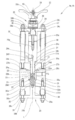
- FIG. 2 is an explanatory view showing the configuration of the corrosion resistance test apparatus according to the embodiment of the present invention.
- the corrosion resistance test apparatuses 4 a and 4 b incorporated in the gap jet method test apparatus 100 described above are capable of rotating the test piece 22 in the chamber 21 into which the test liquid is introduced, and the chamber 21.
- the chamber 21 and the test liquid circulation channel 3 are provided with a test piece mounting tool 23 that holds the self-posture and a reference surface portion 24a facing the test surface portion 22a of the test piece 22 held by the test piece mounting tool 23.
- a nozzle main body 24 to be connected and nozzle main body moving means 25 for moving the nozzle main body 24 relative to the test surface portion 22a are provided.
- the chamber 21 is formed by covering a recess 26 a formed in the main body 26 around the reference axis L with a cover member 27. Although not shown in FIG. 2, bolts are used to connect the main body 26 and the cover member 27 together.
- a through hole 26b that communicates with the recess 26a that forms the chamber 21 is formed in the main body 26 along the reference axis L, and a connection port 26c that communicates with the recess 26a is orthogonal to the reference axis L. Is formed.
- the connection port 26c connects the test liquid circulation flow path 3 and the chamber 21, and the test liquid flows in or out as indicated by solid or broken arrows.
- a holding member 29 holding a test piece mounting tool 23 described later is fitted into the through hole 26b from the outside.
- the holding member 29 is orthogonal to the reference axis L in order to fix the shaft portion 29a at a predetermined position with respect to the main body portion 26 and a shaft portion 29a extending along the reference axis L to hold the test piece mounting tool 23. And a base 29b extending in the direction.
- the holding member 29 is fixed to the main body portion 26 via a plurality of columnar spacers 30 having screw portions 30a and 30b formed at both ends. Specifically, after screwing the screw portion 30a on one end side of each spacer 30 into the screw hole 26d of the main body portion 26, the screw portion 30b on the other end side is passed through the through hole 29c of the base portion 29b and tightened by the nut 31. Are fixed.
- FIG. 3 is an explanatory view of a single prime mover constituting the test piece mounting tool
- FIG. 4 is an explanatory view of the single test piece.
- the prime mover 32 constituting the test piece mounting tool 23 in the present embodiment protrudes in a direction orthogonal to the reference axis L and a screw portion 32 a extending along the reference axis L.
- a flange portion 32b and a spherical crown 32c formed so as to protrude from the flange portion 32b along the reference axis L are provided.
- the prime mover 32 is made of an insulating material that can electrically insulate the test piece 22 and the holding member 29, and the spherical crown 32c is formed with a notch 32d having a cross shape when viewed from the front.
- the test piece 22 is a cylindrical body formed of a test material such as carbon steel, and includes a flat test surface portion 22a orthogonal to the reference axis L, and a test surface portion 22a. And a recess 22b formed on the back side.
- the prime mover 32 holds the test piece 22 so as to be rotatable with respect to the prime mover 32 and to be able to maintain its own posture by pressing the spherical crown 32 c into the recess 22 b of the test piece 22. ing. Note that it is the frictional force generated between the crown 32c and the recess 22b that makes it possible to hold the test piece 22 with respect to the prime mover 32. Therefore, when an external force larger than this frictional force is applied to the test piece 22, the test piece 22 moves so as to rotate along the spherical crown 32c of the prime mover 32.
- the cross-shaped cut 32d formed in the spherical crown 32c of the prime mover 32 enables the spherical crown 32c to be elastically deformed when the spherical crown 32c is press-fitted into the concave portion 22b of the test piece 22.
- the test piece 22 can be attached without difficulty.
- the driving body 32 is fixed to the holding member 29 along the reference axis L by screwing the screw portion 32 a into a screw hole 29 d formed at the tip of the shaft portion 29 a of the holding member 29.
- the test piece 22 is directly attached to the driving body 32, and the function of the driven body connected to the driving body 32 so that the test piece 22 itself can rotate and can maintain its own posture. Plays. In other words, it can be said that the test piece 22 is formed integrally with the driven body.
- the cover member 27 that forms the chamber 21 together with the main body 26 is formed with a through hole 27a along the reference axis L.
- Nozzle body 24 is connected.
- the nozzle body 24 includes a narrow diameter portion 24b having a small diameter and a large diameter portion 24c having a large diameter, and a reference surface portion 24a facing the test surface portion 22a of the test piece 22 is formed at the tip of the small diameter portion 24b.
- the test surface portion 22a intersects with the reference axis L at an angle of 90 ° is illustrated, but the test surface portion 22a may intersect with the reference axis L at an angle other than 90 °.
- a nozzle port 24d through which the test solution flows out or flows is formed at the center of the reference surface portion 24a.
- a connection port 24e connected to the test solution circulation channel 3 is formed on the side surface of the large diameter portion 24c, and the connection port 24e and the nozzle port 24d are connected by a channel 24f extending along the reference axis L. Yes. From the connection port 24e, the test solution flows out or flows in as indicated by solid or broken arrows.
- the large diameter portion 24c of the nozzle body 24 is formed with a screw hole 24g along the reference axis L, and the nozzle body 24 is supported by the nozzle body moving means 25 through the screw hole 24g so as to be movable.
- the connection port 24e formed in the movable nozzle body 24 and the test solution circulation channel 3 are connected by a bendable bellows-like pipe, a nylon tube, or the like.
- the nozzle main body moving means 25 mainly includes a handle 33, a support member 34 that supports the handle 33, and a shaft 35 that is supported by the handle 33 and has a threaded portion 35a formed at the tip.
- the support member 34 that supports the handle 33 is fixed to the cover member 27 via a plurality of columnar spacers 36 having screw portions 36a and 36b formed at both ends. Specifically, after screwing the screw portion 36 a on one end side of each spacer 36 into the screw hole 27 b of the cover member 27, the screw portion 36 b on the other end side is passed through the through hole 34 a of the support member 34, and It is tightened and fixed.
- a collar 38 with a bearing is interposed between the support member 34 and the handle 33, whereby the handle 33 is supported by the support member 34 at a predetermined distance from the support member 34.
- the handle 33 is formed with a through hole 33 a along the reference axis L, and one end of the shaft 35 is fitted into the through hole 33 a and is fixed from above the handle 33 via a bolt 39 and a washer 40.
- the shaft 35 is attached to the handle 33 along the reference axis L.
- a shaft through hole 34b is formed in the support member 34 along the reference axis L.
- the shaft 35 is formed with a screw portion 35a at the other end (tip) passing through the shaft through hole 34b. Are screwed into the screw holes 24g of the nozzle body 24.
- the spherical crown 32c of the prime mover 32 constituting the test piece mounting tool 23 is press-fitted into the recess 22b of the test piece 22, and then the original The screw part 32a of the moving body 32 is screwed into the screw hole 29d of the holding member 29, and both are fixed.
- the holding member 29 to which the prime mover 32 is attached is fitted into the through hole 26 b of the main body 26 and fixed with the nut 31.
- test piece 22 is attached to the spherical crown 32c of the prime mover 32 without being controlled in its posture, and the test surface portion 22a is perpendicular to the reference axis L, that is, parallel to the reference surface portion 24a. It is unknown whether it is.
- the nozzle body moving means 25 described above is used, the nozzle body 24 is moved in the chamber 21, the reference surface portion 24a is brought into contact with the test surface portion 22a of the test piece 22, and the test surface portion 22a is brought into contact with the reference surface portion.
- the posture of the test piece 22 is adjusted by following 24a. Specifically, the handle 33 of the nozzle body moving means 25 is turned counterclockwise, and the nozzle body 24 is moved toward the test surface portion 22 a of the test piece 22 in the chamber 21.
- the handle 33 is rotated clockwise, and the nozzle body 24 is separated from the test surface portion 22a in the chamber 21 so that the reference surface portion 24a is located at a predetermined distance from the test surface portion 22a.
- a gap of a predetermined distance is formed between the test surface portion 22a of the test piece 22 and the reference surface portion 24a of the nozzle body 24, and the intended corrosion resistance test can be performed with high accuracy.
- the possibility that the posture of the test piece 22 changes can be reduced as much as possible.
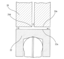
- FIG. 5 is an explanatory view showing the flow of the test liquid generated in the corrosion resistance test apparatus arranged on the upstream side in the gap jet method test apparatus shown in FIG. 1
- FIG. 6 is the gap jet method test apparatus shown in FIG. It is explanatory drawing which shows the flow of the test liquid which has arisen in the corrosion resistance test apparatus of a downstream.
- a test solution is introduced from a connection port 26 c (see FIG. 2) formed in the main body portion 26. Therefore, the test liquid flows toward the nozzle opening 24 d of the nozzle body 24 through a gap formed between the test surface portion 22 a of the test piece 22 and the reference surface portion 24 a of the nozzle body 24. Since the flow shown in FIG. 5 forms a laminar flow that does not cause a turbulent flow disturbance, a state of corrosion / erosion in the laminar flow is created on the test surface portion 22a.
- the test solution is introduced from the connection port 24 e (see FIG. 2) formed in the nozzle body 24. Therefore, after the test liquid is ejected from the nozzle opening 24d of the nozzle body 24 toward the test surface portion 22a of the test piece 22, the gap formed between the test surface portion 22a and the reference surface portion 24a is directed toward the outer edge of the test surface portion 22a. Flowing. Since the flow shown in FIG. 6 forms a turbulent flow that causes a turbulent flow turbulence, a state of corrosion / erosion in the turbulent flow is created on the test surface portion 22a.
- test pieces 22 are taken out from the corrosion resistance test apparatuses 4a and 4b, respectively, and the state of corrosion / erosion occurring on the test surface portion 22a is measured using a surface roughness meter or an electron microscope. Observe. As a result, it is possible to investigate the state of corrosion / erosion in laminar flow and the state of corrosion / erosion in turbulent flow.
- the posture of the test piece 22 is adjusted by moving the nozzle body 24, it is not necessary to move the test piece 22 whose posture has been adjusted in the chamber 21, The possibility that the posture of the test piece 22 changes can be reduced as much as possible. As a result, a more reliable corrosion resistance test can be performed, and useful data can be obtained for preventing corrosion and erosion of various flow paths including the boiler water system.
- the handle 33, the support member 34 that supports the handle, and the shaft 35 that is supported by the handle 33 and screwed into the screw hole 24g of the nozzle body 24 are used as the nozzle body moving means 25.
- the configuration of the nozzle body moving means 25 is not limited to this.
- a known rack-and-pinion method that is used to move the lens barrel of the optical microscope up and down can be suitably used.
- the handle 33 is manually turned to separate the reference surface portion 24a of the nozzle body 24 from the test surface portion 22a of the test piece 22 by a predetermined distance.
- An optical path difference type autofocus device may be incorporated so that the reference surface portion 24a of the nozzle body 24 is automatically positioned at a predetermined distance from the test surface portion 22a of the test piece 22 after adjusting the posture of the test piece 22. .
Landscapes
- Life Sciences & Earth Sciences (AREA)
- Biodiversity & Conservation Biology (AREA)
- Ecology (AREA)
- Environmental & Geological Engineering (AREA)
- Environmental Sciences (AREA)
- Physics & Mathematics (AREA)
- Health & Medical Sciences (AREA)
- Chemical & Material Sciences (AREA)
- Analytical Chemistry (AREA)
- Biochemistry (AREA)
- General Health & Medical Sciences (AREA)
- General Physics & Mathematics (AREA)
- Immunology (AREA)
- Pathology (AREA)
- Testing Resistance To Weather, Investigating Materials By Mechanical Methods (AREA)
Description
この発明は、耐食試験装置に関し、詳しくは液体の流路を構成する材料の耐食試験に用いられる耐食試験装置に関する。
プラント等を含む各種施設の液体の流路において、特にポンプ等の可動部、あるいは曲がり部分や拡大・縮小部分では、流動する液体により化学的あるいは電気化学的腐食および物理的浸食が見られる。
例えば、火力発電プラント等のボイラ水系では、一般に配管等の流路を構成する材料として炭素鋼が使用されているが、上記した流れの乱れの激しい部分や剪断力が増加する部分では、高温高圧のボイラプラント水の供給により保護性酸化被膜が局部的に破壊されて減肉を生じる場合がある。
このような現象は高温高圧のボイラプラント水に限らず、様々な液体の流路において発生する。
そのため、流路に使用される材料の検討あるいは流体の供給方法の改善を通じて腐食環境に適合した耐食手段を確立すべく、従来から耐食試験が行われている。
例えば、火力発電プラント等のボイラ水系では、一般に配管等の流路を構成する材料として炭素鋼が使用されているが、上記した流れの乱れの激しい部分や剪断力が増加する部分では、高温高圧のボイラプラント水の供給により保護性酸化被膜が局部的に破壊されて減肉を生じる場合がある。
このような現象は高温高圧のボイラプラント水に限らず、様々な液体の流路において発生する。
そのため、流路に使用される材料の検討あるいは流体の供給方法の改善を通じて腐食環境に適合した耐食手段を確立すべく、従来から耐食試験が行われている。
従来の耐食試験装置としては、試験液が導入されるチャンバと、チャンバ内で試験片を回動可能かつ自己姿勢保持可能に保持する試験片装着具と、試験片装着具に保持された試験片の試験面部と対向する基準面部を有しチャンバと流路とを接続するノズル本体と、チャンバ内で試験片装着具を移動させる試験片移動手段とを備えた耐食試験装置が知られている(例えば、特許文献1参照)。
この耐食試験装置は、試験片移動手段により試験片の試験面部をノズル本体の基準面部に当接させて試験片の姿勢を基準面部に倣わせた後、基準面部から試験面部を所定の距離だけ離間させて試験液の流路を形成するように構成されている。
この耐食試験装置は、試験片移動手段により試験片の試験面部をノズル本体の基準面部に当接させて試験片の姿勢を基準面部に倣わせた後、基準面部から試験面部を所定の距離だけ離間させて試験液の流路を形成するように構成されている。
特許文献1に記載の耐食試験装置では、試験片装着具に回動可能かつ自己姿勢保持可能に保持された試験片の試験面部を試験片移動手段によってノズル本体の基準面部に当接させ、試験面部を基準面部に倣わせることにより試験片の姿勢を所定の姿勢に調整することができる。
このため、特許文献1に記載の耐食試験装置によれば、試験片の位置決めを容易かつ正確に行うことができ、耐食試験の試験精度も向上する。
しかしながら、特許文献1に記載のものでは、試験片の試験面部を基準面部に当接させて姿勢を調整した後、試験面部を基準面部から所定の距離だけ離間させる際に試験片の姿勢が変化してしまうおそれがある。
このため、特許文献1に記載の耐食試験装置によれば、試験片の位置決めを容易かつ正確に行うことができ、耐食試験の試験精度も向上する。
しかしながら、特許文献1に記載のものでは、試験片の試験面部を基準面部に当接させて姿勢を調整した後、試験面部を基準面部から所定の距離だけ離間させる際に試験片の姿勢が変化してしまうおそれがある。
この発明は以上のような事情を考慮してなされたもので、試験片の姿勢が変化する可能性を極力低減することのできる耐食試験装置を提供するものである。
この発明は、耐食試験を必要とする装置の流路に介設される耐食試験装置であって、試験液が導入されるチャンバと、チャンバ内で試験片を回動可能かつ自己姿勢保持可能に保持する試験片装着具と、試験片装着具に保持された試験片の試験面部と対向する基準面部を有しチャンバと流路とを接続するノズル本体と、試験面部に対してノズル本体を移動させるノズル本体移動手段とを備え、
ノズル本体移動手段は、ノズル本体を試験片の試験面部へ向かって移動させ基準面部を試験片の試験面部に当接させて試験面部を基準面部に倣わせた後、基準面部が試験面部から所定の距離に位置するようにノズル本体を試験面部から離間させて試験液の流路を形成するように構成されている耐食試験装置を提供するものである。
ノズル本体移動手段は、ノズル本体を試験片の試験面部へ向かって移動させ基準面部を試験片の試験面部に当接させて試験面部を基準面部に倣わせた後、基準面部が試験面部から所定の距離に位置するようにノズル本体を試験面部から離間させて試験液の流路を形成するように構成されている耐食試験装置を提供するものである。
この発明によれば、試験片の姿勢を調整する際に、ノズル本体を試験片の試験面部に向かって移動させ、基準面部を試験片の試験面部に当接させて試験面部を基準面部に倣わせた後、基準面部が試験面部から所定の距離に位置するようにノズル本体を試験面部から離間させて試験液の流路を形成するように構成されている。そのため、姿勢調整のなされた試験片をチャンバ内で移動させずに済み、試験片の姿勢が変化する可能性を極力低減することができる。
この発明による耐食試験装置は、耐食試験を必要とする装置の流路に介設される耐食試験装置であって、試験液が導入されるチャンバと、チャンバ内で試験片を回動可能かつ自己姿勢保持可能に保持する試験片装着具と、試験片装着具に保持された試験片の試験面部と対向する基準面部を有しチャンバと流路とを接続するノズル本体と、試験面部に対してノズル本体を移動させるノズル本体移動手段とを備える。
ノズル本体移動手段は、ノズル本体を試験片の試験面部に向かって移動させ基準面部を試験片の試験面部に当接させて試験面部を基準面部に倣わせた後、基準面部が試験面部から所定の距離に位置するようにノズル本体を試験面部から離間させて試験液の流路を形成するように構成されている。
ノズル本体移動手段は、ノズル本体を試験片の試験面部に向かって移動させ基準面部を試験片の試験面部に当接させて試験面部を基準面部に倣わせた後、基準面部が試験面部から所定の距離に位置するようにノズル本体を試験面部から離間させて試験液の流路を形成するように構成されている。
この発明による耐食試験装置において、流路とは試験液が流される配管を意味する。また、試験液とは、流路内を流れ耐食試験に用いられる液体を意味し、液体の種類は特に限定されない。
チャンバとは試験液が流入する室を意味し、後述のノズル本体によって流路と接続される。
ノズル本体とはチャンバと流路とを接続する部材を意味し、試験片の試験面部と対向する基準面部を有する。
ノズル本体移動手段とは、試験面部に対してノズル本体を移動させる駆動機構全般を意味する。
チャンバとは試験液が流入する室を意味し、後述のノズル本体によって流路と接続される。
ノズル本体とはチャンバと流路とを接続する部材を意味し、試験片の試験面部と対向する基準面部を有する。
ノズル本体移動手段とは、試験面部に対してノズル本体を移動させる駆動機構全般を意味する。
この発明による耐食試験装置において、ノズル本体は試験面部に対して垂直方向に延びる基準軸に沿ってネジ穴が形成され、ノズル本体移動手段はノズル本体のネジ穴に螺合するネジ部と、ネジ部に取り付けられたハンドルとからなっていてもよい。
このような構成によれば、簡易な構成で確実かつ正確にノズル本体を移動させることができ、信頼性に優れた耐食試験装置を提供できる。
このような構成によれば、簡易な構成で確実かつ正確にノズル本体を移動させることができ、信頼性に優れた耐食試験装置を提供できる。
また、この発明による耐食試験装置において、ノズル本体は試験面部と対向する基準面部に試験液が流出又は流入するノズル口が形成されていてもよい。
このような構成によれば、基準面部に試験液が流出又は流入するノズル口が形成されるので、試験面部に対して所定の方向で試験液を流し易くなり、試験精度が向上する。
このような構成によれば、基準面部に試験液が流出又は流入するノズル口が形成されるので、試験面部に対して所定の方向で試験液を流し易くなり、試験精度が向上する。
また、この発明による耐食試験装置において、試験片装着具は、球状の球冠を備えた原動体と、球冠が圧入される凹部を備えた従動体とからなり、従動体は一端側が原動体に対して回動可能かつ自己姿勢保持可能に連結され、他端側が試験片を装着可能に構成されていてもよい。
このような構成によれば、原動体に設けられた球冠が従動体の凹部に圧入されるので、原動体に対する従動体の姿勢の自由度が高まり、試験片を精密に姿勢調整できるようになる。
なお、上記構成において従動体を原動体に対して自己姿勢保持可能にするのは原動体の球冠と従動体の凹部との間に生じる摩擦力であり、従動体はこの摩擦力よりも大きい外力を受けると原動体に対して回動し姿勢を変化させる。
このような構成によれば、原動体に設けられた球冠が従動体の凹部に圧入されるので、原動体に対する従動体の姿勢の自由度が高まり、試験片を精密に姿勢調整できるようになる。
なお、上記構成において従動体を原動体に対して自己姿勢保持可能にするのは原動体の球冠と従動体の凹部との間に生じる摩擦力であり、従動体はこの摩擦力よりも大きい外力を受けると原動体に対して回動し姿勢を変化させる。
試験片装着具が原動体と従動体とからなる上記構成において、従動体は試験片と一体に形成されていてもよい。
このような構成によれば、試験片と従動体が一体に形成されるので、試験片を従動体に装着する手間が省けるばかりでなく、より精密な姿勢調整が可能となる。
このような構成によれば、試験片と従動体が一体に形成されるので、試験片を従動体に装着する手間が省けるばかりでなく、より精密な姿勢調整が可能となる。
以下、図面に基づいてこの発明の実施形態に係る耐食試験装置について説明する。
本発明の実施形態に係る耐食試験装置について図1~6に基づいて説明する。図1は本発明の実施形態に係る耐食試験装置が組み込まれた隙間噴流法試験装置の全体構成を示す説明図である。
図1に示されるように、隙間噴流法試験装置100は、水質調整タンク1およびポンプ2と、ポンプ2の駆動により水質調整タンク1から供給された試験液を循環可能に流動させる試験液循環流路3と、試験液循環流路3に介設された2つの耐食試験装置4a,4bと、試験液循環流路3に供給された試験液を排出する試験液排出流路5とから主に構成されている。
図1に示されるように、隙間噴流法試験装置100は、水質調整タンク1およびポンプ2と、ポンプ2の駆動により水質調整タンク1から供給された試験液を循環可能に流動させる試験液循環流路3と、試験液循環流路3に介設された2つの耐食試験装置4a,4bと、試験液循環流路3に供給された試験液を排出する試験液排出流路5とから主に構成されている。
試験液を収容する水質調整タンク1は、収容された試験液に空気または窒素ガスを供給するガス供給手段6と、ヒータ7と、試験液中の溶存酸素濃度を測定する供給試験液用DOメータ8を備える。
試験液循環流路3には、水質調整タンク1から下流に向かって、ポンプ2、流量調整用バイパス路9、流量調整用バルブ10a,10b、流量計11a,11b、耐食試験装置4a,4bが順に介設されている。流量調整用バイパス路9にはバルブ12が介設されている。
耐食試験装置4a,4bは、試験液循環流路3に直列に保持されており、両者間にはフィルター13が介設されている。ヒータ7および耐食試験装置4a,4bには、それぞれ図示しない温度指示調節計が取り付けられている。
試験液循環流路3には、水質調整タンク1から下流に向かって、ポンプ2、流量調整用バイパス路9、流量調整用バルブ10a,10b、流量計11a,11b、耐食試験装置4a,4bが順に介設されている。流量調整用バイパス路9にはバルブ12が介設されている。
耐食試験装置4a,4bは、試験液循環流路3に直列に保持されており、両者間にはフィルター13が介設されている。ヒータ7および耐食試験装置4a,4bには、それぞれ図示しない温度指示調節計が取り付けられている。
図2は本発明の実施形態に係る耐食試験装置の構成を示す説明図である。
図2に示されるように、上述の隙間噴流法試験装置100に組み込まれた耐食試験装置4a,4bは、試験液が導入されるチャンバ21と、チャンバ21内で試験片22を回動可能かつ自己姿勢保持可能に保持する試験片装着具23と、試験片装着具23に保持された試験片22の試験面部22aと対向する基準面部24aを有しチャンバ21と試験液循環流路3とを接続するノズル本体24と、試験面部22aに対してノズル本体24を移動させるノズル本体移動手段25とを備えている。
図2に示されるように、上述の隙間噴流法試験装置100に組み込まれた耐食試験装置4a,4bは、試験液が導入されるチャンバ21と、チャンバ21内で試験片22を回動可能かつ自己姿勢保持可能に保持する試験片装着具23と、試験片装着具23に保持された試験片22の試験面部22aと対向する基準面部24aを有しチャンバ21と試験液循環流路3とを接続するノズル本体24と、試験面部22aに対してノズル本体24を移動させるノズル本体移動手段25とを備えている。
チャンバ21は基準軸Lを中心として本体部26に形成された凹部26aをカバー部材27によって覆うことにより形成されている。図2には図示しないが、本体部26とカバー部材27をつなぎ合わせるためにボルトが使用されている。
また、本体部26にはチャンバ21を形成する上記の凹部26aと連通する貫通孔26bが基準軸Lに沿って形成されると共に、凹部26aと連通する接続口26cが基準軸Lと直交するように形成されている。接続口26cは試験液循環流路3とチャンバ21とを接続し、実線または破線の矢印で示すように試験液が流入または流出する。また、貫通孔26bには後述の試験片装着具23を保持した保持部材29が外部から嵌め入れられる。
また、本体部26にはチャンバ21を形成する上記の凹部26aと連通する貫通孔26bが基準軸Lに沿って形成されると共に、凹部26aと連通する接続口26cが基準軸Lと直交するように形成されている。接続口26cは試験液循環流路3とチャンバ21とを接続し、実線または破線の矢印で示すように試験液が流入または流出する。また、貫通孔26bには後述の試験片装着具23を保持した保持部材29が外部から嵌め入れられる。
保持部材29は試験片装着具23を保持するために基準軸Lに沿って延びる軸部29aと、本体部26に対して軸部29aを所定の位置で固定するために基準軸Lと直交する方向に延びる基部29bとから構成されている。
保持部材29は、両端にネジ部30a,30bが形成された複数の円柱状のスペーサ30を介して本体部26に固定される。詳しくは、各スペーサ30の一端側のネジ部30aを本体部26のネジ穴26dに螺合させた上で、他端側のネジ部30bを基部29bの貫通孔29cに通し、ナット31によって締め付けて固定している。
保持部材29は、両端にネジ部30a,30bが形成された複数の円柱状のスペーサ30を介して本体部26に固定される。詳しくは、各スペーサ30の一端側のネジ部30aを本体部26のネジ穴26dに螺合させた上で、他端側のネジ部30bを基部29bの貫通孔29cに通し、ナット31によって締め付けて固定している。
図3は試験片装着具を構成する原動体単体の説明図、図4は試験片単体の説明図である。
図2および図3に示されるように、本実施形態において試験片装着具23を構成する原動体32は、基準軸Lに沿って延びるネジ部32aと、基準軸Lと直交する方向に張り出したフランジ部32bと、フランジ部32bから基準軸Lに沿って突出するように形成された球状の球冠32cとを備えている。原動体32は試験片22と保持部材29とを電気的に絶縁できる絶縁材料からなり、球冠32cには正面からみて十字状となる切り込み32dが形成されている。
図2および図3に示されるように、本実施形態において試験片装着具23を構成する原動体32は、基準軸Lに沿って延びるネジ部32aと、基準軸Lと直交する方向に張り出したフランジ部32bと、フランジ部32bから基準軸Lに沿って突出するように形成された球状の球冠32cとを備えている。原動体32は試験片22と保持部材29とを電気的に絶縁できる絶縁材料からなり、球冠32cには正面からみて十字状となる切り込み32dが形成されている。
一方、図2および図4に示されるように、試験片22は、炭素鋼などの試験材料から形成された円柱体であり、基準軸Lと直交する平坦な試験面部22aと、試験面部22aの裏側に形成された凹部22bとを備えている。
図2に示されるように、原動体32は球冠32cが試験片22の凹部22bに圧入されることにより、試験片22を原動体32に対して回動可能かつ自己姿勢保持可能に保持している。なお、試験片22を原動体32に対して自己姿勢保持可能としているのは球冠32cと凹部22bとの間に生ずる摩擦力である。したがって、この摩擦力よりも大きい外力が試験片22に加わると試験片22は原動体32の球冠32cに沿って回動するように移動する。
図2に示されるように、原動体32は球冠32cが試験片22の凹部22bに圧入されることにより、試験片22を原動体32に対して回動可能かつ自己姿勢保持可能に保持している。なお、試験片22を原動体32に対して自己姿勢保持可能としているのは球冠32cと凹部22bとの間に生ずる摩擦力である。したがって、この摩擦力よりも大きい外力が試験片22に加わると試験片22は原動体32の球冠32cに沿って回動するように移動する。
原動体32の球冠32cに形成された十字状の切り込み32dは、球冠32cを試験片22の凹部22bに圧入する際に球冠32cが弾性変形することを可能とし、これにより原動体32に対して試験片22を無理なく装着することが可能となっている。
また、原動体32はネジ部32aが、保持部材29の軸部29aの先端に形成されたネジ穴29dに螺合することにより基準軸Lに沿って保持部材29に固定されている。
このように、本実施形態では、試験片22が原動体32に直接取り付けられており、試験片22そのものが原動体32に対して回動可能かつ自己姿勢保持可能に連結される従動体の機能を果たしている。換言すれば、試験片22は従動体と一体に形成されているとも言える。
また、原動体32はネジ部32aが、保持部材29の軸部29aの先端に形成されたネジ穴29dに螺合することにより基準軸Lに沿って保持部材29に固定されている。
このように、本実施形態では、試験片22が原動体32に直接取り付けられており、試験片22そのものが原動体32に対して回動可能かつ自己姿勢保持可能に連結される従動体の機能を果たしている。換言すれば、試験片22は従動体と一体に形成されているとも言える。
図2に示されるように、本体部26と共にチャンバ21を形成するカバー部材27には、基準軸Lに沿って貫通孔27aが形成され、この貫通孔27aにチャンバ21と試験液循環流路3とを接続するノズル本体24が嵌め入れられている。
ノズル本体24は直径の細い細径部24bと直径の大きい大径部24cとからなり、細径部24bの先端に試験片22の試験面部22aと対向する基準面部24aが形成されている。なお、本実施形態では、試験面部22aが基準軸Lと90°の角度で交わる場合を例示しているが、試験面部22aが基準軸Lと90°以外の角度で交わってもよい。
基準面部24aの中心には試験液が流出または流入するノズル口24dが形成されている。また、大径部24cの側面には試験液循環流路3に接続される接続口24eが形成され、接続口24eとノズル口24dとは基準軸Lに沿って延びる流路24fによって繋がれている。接続口24eからは実線または破線の矢印で示すように試験液が流出または流入する。
また、ノズル本体24の大径部24cには基準軸Lに沿ってネジ穴24gが形成され、このネジ穴24gを介してノズル本体24がノズル本体移動手段25によって移動可能に支持されている。
なお、図示しないが、移動可能なノズル本体24に形成された接続口24eと試験液循環流路3とは屈曲可能な蛇腹状のパイプやナイロンチューブ等により接続される。
ノズル本体24は直径の細い細径部24bと直径の大きい大径部24cとからなり、細径部24bの先端に試験片22の試験面部22aと対向する基準面部24aが形成されている。なお、本実施形態では、試験面部22aが基準軸Lと90°の角度で交わる場合を例示しているが、試験面部22aが基準軸Lと90°以外の角度で交わってもよい。
基準面部24aの中心には試験液が流出または流入するノズル口24dが形成されている。また、大径部24cの側面には試験液循環流路3に接続される接続口24eが形成され、接続口24eとノズル口24dとは基準軸Lに沿って延びる流路24fによって繋がれている。接続口24eからは実線または破線の矢印で示すように試験液が流出または流入する。
また、ノズル本体24の大径部24cには基準軸Lに沿ってネジ穴24gが形成され、このネジ穴24gを介してノズル本体24がノズル本体移動手段25によって移動可能に支持されている。
なお、図示しないが、移動可能なノズル本体24に形成された接続口24eと試験液循環流路3とは屈曲可能な蛇腹状のパイプやナイロンチューブ等により接続される。
ノズル本体移動手段25は、ハンドル33と、ハンドル33を支持する支持部材34と、ハンドル33に支持され先端にネジ部35aが形成されたシャフト35とから主に構成されている。
ハンドル33を支持する支持部材34は両端にネジ部36a,36bが形成された複数の円柱状のスペーサ36を介してカバー部材27に固定される。詳しくは、各スペーサ36の一端側のネジ部36aをカバー部材27のネジ穴27bに螺合させた上で、他端側のネジ部36bを支持部材34の貫通孔34aに通し、ナット37によって締め付けて固定している。
支持部材34とハンドル33との間にはベアリング付きのカラー38が介設され、これによってハンドル33は支持部材34から所定の間隔を空けるようにして支持部材34に支持される。
ハンドル33を支持する支持部材34は両端にネジ部36a,36bが形成された複数の円柱状のスペーサ36を介してカバー部材27に固定される。詳しくは、各スペーサ36の一端側のネジ部36aをカバー部材27のネジ穴27bに螺合させた上で、他端側のネジ部36bを支持部材34の貫通孔34aに通し、ナット37によって締め付けて固定している。
支持部材34とハンドル33との間にはベアリング付きのカラー38が介設され、これによってハンドル33は支持部材34から所定の間隔を空けるようにして支持部材34に支持される。
ハンドル33は基準軸Lに沿って貫通孔33aが形成され、この貫通孔33aにシャフト35の一端が嵌め入れられてハンドル33の上側からボルト39およびワッシャ40を介して固定される。これによりシャフト35は基準軸Lに沿ってハンドル33に取り付けられる。
支持部材34には基準軸Lに沿ってシャフト用貫通孔34bが形成され、シャフト35はシャフト用貫通孔34bを貫通した他端(先端)にネジ部35aが形成され、このネジ部35aが上述のノズル本体24のネジ穴24gに螺合している。
支持部材34には基準軸Lに沿ってシャフト用貫通孔34bが形成され、シャフト35はシャフト用貫通孔34bを貫通した他端(先端)にネジ部35aが形成され、このネジ部35aが上述のノズル本体24のネジ穴24gに螺合している。
ハンドル33を反時計方向に回すと、シャフト35の先端に形成されたネジ部35aとノズル本体24のネジ穴24gとの螺合が浅くなり、ノズル本体24は基準面部24aと試験面部22aとの距離が縮まるように移動する。
一方、ハンドル33を時計方向に回すと、シャフト35の先端に形成されたネジ部35aとノズル本体24のネジ穴24gとの螺合が深くなり、ノズル本体24は基準面部24aが試験片22の試験面部22aから離間するように移動する。
一方、ハンドル33を時計方向に回すと、シャフト35の先端に形成されたネジ部35aとノズル本体24のネジ穴24gとの螺合が深くなり、ノズル本体24は基準面部24aが試験片22の試験面部22aから離間するように移動する。
試験片22を耐食試験装置4a,4bに設置する際には、まず、上述の試験片装着具23を構成する原動体32の球冠32cを試験片22の凹部22bに圧入した上で、原動体32のネジ部32aを保持部材29のネジ穴29dに螺合させて両者を固定する。
次いで、原動体32が取り付けられた保持部材29を本体部26の貫通孔26bに嵌め入れ、ナット31で固定する。
この状態では、試験片22は原動体32の球冠32cにその姿勢について制御されることなく取り付けられており、試験面部22aが基準軸Lに対して直交する姿勢、すなわち基準面部24aと平行になっているかは不明である。
次いで、原動体32が取り付けられた保持部材29を本体部26の貫通孔26bに嵌め入れ、ナット31で固定する。
この状態では、試験片22は原動体32の球冠32cにその姿勢について制御されることなく取り付けられており、試験面部22aが基準軸Lに対して直交する姿勢、すなわち基準面部24aと平行になっているかは不明である。
そこで、本実施形態では上述のノズル本体移動手段25を利用し、チャンバ21内でノズル本体24を移動させて基準面部24aを試験片22の試験面部22aに当接させ、試験面部22aを基準面部24aに倣わせることにより、試験片22の姿勢を調整する。
詳しくは、ノズル本体移動手段25のハンドル33を反時計方向に回し、チャンバ21内でノズル本体24を試験片22の試験面部22aに向かって移動させる。
ノズル本体24の基準面部24aが試験片22の試験面部22aに当接し、試験面部22aが基準面部24aに倣うように試験片22の姿勢が調整されると、試験面部22aと基準面部24aが平行となりハンドル33がそれ以上回らなくなるので、そこでハンドル33の回転を止める。
詳しくは、ノズル本体移動手段25のハンドル33を反時計方向に回し、チャンバ21内でノズル本体24を試験片22の試験面部22aに向かって移動させる。
ノズル本体24の基準面部24aが試験片22の試験面部22aに当接し、試験面部22aが基準面部24aに倣うように試験片22の姿勢が調整されると、試験面部22aと基準面部24aが平行となりハンドル33がそれ以上回らなくなるので、そこでハンドル33の回転を止める。
次いで、ハンドル33を時計方向に回し、基準面部24aが試験面部22aから所定の距離に位置するようにチャンバ21内でノズル本体24を試験面部22aから離間させる。
これにより、試験片22の試験面部22aとノズル本体24の基準面部24aとの間に所定距離の間隙が形成され、目的とする耐食試験を高精度に実施することが可能となる。
この際、本実施形態では、姿勢調整の済んだ試験片22をチャンバ21内で移動させずに済むので、試験片22の姿勢が変化する可能性を極力低減することができる。
これにより、試験片22の試験面部22aとノズル本体24の基準面部24aとの間に所定距離の間隙が形成され、目的とする耐食試験を高精度に実施することが可能となる。
この際、本実施形態では、姿勢調整の済んだ試験片22をチャンバ21内で移動させずに済むので、試験片22の姿勢が変化する可能性を極力低減することができる。
図5は図1に示される隙間噴流法試験装置において上流側に配置された耐食試験装置内で生じている試験液の流れを示す説明図、図6は図1に示される隙間噴流法試験装置において下流側の耐食試験装置内で生じている試験液の流れを示す説明図である。
図1および図5に示されるように、上流側に配置された耐食試験装置4aでは、本体部26に形成された接続口26c(図2参照)から試験液が導入される。そのため、試験液は試験片22の試験面部22aとノズル本体24の基準面部24aとの間に形成された間隙をノズル本体24のノズル口24dに向かって流れる。
図5に示される流れは、流れの激しい乱れを生じない層流を形成するため、層流における腐食・浸食の状況が試験面部22a上に作り出される。
図5に示される流れは、流れの激しい乱れを生じない層流を形成するため、層流における腐食・浸食の状況が試験面部22a上に作り出される。
一方、図1および図6に示されるように、下流側に配置された耐食試験装置4bでは、ノズル本体24に形成された接続口24e(図2参照)から試験液が導入される。そのため、試験液はノズル本体24のノズル口24dから試験片22の試験面部22aに向かって噴出した後、試験面部22aと基準面部24aとの間に形成された間隙を試験面部22aの外縁へ向かって流れる。
図6に示される流れは、流れの激しい乱れを生じる乱流を形成するため、乱流における腐食・浸食の状況が試験面部22a上に作り出される。
図6に示される流れは、流れの激しい乱れを生じる乱流を形成するため、乱流における腐食・浸食の状況が試験面部22a上に作り出される。
一定の時間、耐食試験を実施した後、耐食試験装置4a,4bから試験片22をそれぞれ取り出し、試験面部22aに生じた腐食・浸食の状況を表面粗さ計や電子顕微鏡等を用いて測定・観察する。これにより、層流における腐食・浸食の状況と乱流における腐食・浸食の状況を調べることができる。
以上、詳細に説明したように、本実施形態では、ノズル本体24を移動させて試験片22の姿勢を調整するので、姿勢調整の済んだ試験片22をチャンバ21内で移動させずに済み、試験片22の姿勢が変化する可能性を極力低減することができる。
この結果、より信頼性の高い耐食試験を実施することが可能となり、ボイラ水系をはじめとする様々な流路の腐食や浸食の防止を図るうえで有用なデータを得ることができる。
この結果、より信頼性の高い耐食試験を実施することが可能となり、ボイラ水系をはじめとする様々な流路の腐食や浸食の防止を図るうえで有用なデータを得ることができる。
なお、上述の実施形態ではノズル本体移動手段25として、ハンドル33と、ハンドルを支持する支持部材34と、ハンドル33に支持されノズル本体24のネジ穴24gに螺合するシャフト35とを用いたが、ノズル本体移動手段25の構成はこれに限定されるものではない。ノズル本体を移動させる手段としては、光学顕微鏡の鏡筒を上下させるのに利用されている公知のラック・アンド・ピニオン方式なども好適に利用できる。
また、上述の実施形態では、試験片22の姿勢調整後、手動でハンドル33を回してノズル本体24の基準面部24aを試験片22の試験面部22aから所定の距離だけ離間させたが、公知の光路差方式のオートフォーカス装置を組み込み、試験片22の姿勢調整後、ノズル本体24の基準面部24aが試験片22の試験面部22aから自動的に所定の距離に位置するように構成してもよい。
また、上述の実施形態では、試験片22の姿勢調整後、手動でハンドル33を回してノズル本体24の基準面部24aを試験片22の試験面部22aから所定の距離だけ離間させたが、公知の光路差方式のオートフォーカス装置を組み込み、試験片22の姿勢調整後、ノズル本体24の基準面部24aが試験片22の試験面部22aから自動的に所定の距離に位置するように構成してもよい。
4a,4b 耐食試験装置
21 チャンバ
22 試験片
22a 試験面部
23 試験片装着具
24 ノズル本体
24a 基準面部
24d ノズル口
24e,26c 接続口
24f 流路
24g ネジ穴
25 ノズル本体移動手段
32 原動体
32c 球冠
33 ハンドル
34 支持部材
35 シャフト
35a ネジ部
21 チャンバ
22 試験片
22a 試験面部
23 試験片装着具
24 ノズル本体
24a 基準面部
24d ノズル口
24e,26c 接続口
24f 流路
24g ネジ穴
25 ノズル本体移動手段
32 原動体
32c 球冠
33 ハンドル
34 支持部材
35 シャフト
35a ネジ部
Claims (5)
- 耐食試験を必要とする装置の流路に介設される耐食試験装置であって、試験液が導入されるチャンバと、チャンバ内で試験片を回動可能かつ自己姿勢保持可能に保持する試験片装着具と、試験片装着具に保持された試験片の試験面部と対向する基準面部を有しチャンバと流路とを接続するノズル本体と、試験面部に対してノズル本体を移動させるノズル本体移動手段とを備え、
ノズル本体移動手段は、ノズル本体を試験片の試験面部に向かって移動させ基準面部を試験片の試験面部に当接させて試験面部を基準面部に倣わせた後、基準面部が試験面部から所定の距離に位置するようにノズル本体を試験面部から離間させて試験液の流路を形成するように構成されている耐食試験装置。 - ノズル本体は試験面部に対して垂直方向に延びる基準軸に沿ってネジ穴が形成され、ノズル本体移動手段はノズル本体のネジ穴に螺合するネジ部と、ネジ部に取り付けられたハンドルとからなる請求項1に記載の耐食試験装置。
- ノズル本体は試験面部と対向する基準面部に試験液が流出又は流入するノズル口が形成されてなる請求項1又は2に記載の耐食試験装置。
- 試験片装着具は、球状の球冠を備えた原動体と、球冠が圧入される凹部を備えた従動体とからなり、従動体は一端側が原動体に対して回動可能かつ自己姿勢保持可能に連結され、他端側が試験片を装着可能に構成される請求項1~3のいずれか1つに記載の耐食試験装置。
- 従動体が試験片と一体に形成されてなる請求項4に記載の耐食試験装置。
Priority Applications (2)
| Application Number | Priority Date | Filing Date | Title |
|---|---|---|---|
| EP13800270.4A EP2860512A4 (en) | 2012-06-08 | 2013-05-30 | DEVICE FOR TESTING CORROSION RESISTANCE |
| US14/405,607 US20150153264A1 (en) | 2012-06-08 | 2013-05-30 | Corrosion- resistant test device |
Applications Claiming Priority (2)
| Application Number | Priority Date | Filing Date | Title |
|---|---|---|---|
| JP2012131038A JP2013253932A (ja) | 2012-06-08 | 2012-06-08 | 耐食試験装置 |
| JP2012-131038 | 2012-06-08 |
Publications (1)
| Publication Number | Publication Date |
|---|---|
| WO2013183538A1 true WO2013183538A1 (ja) | 2013-12-12 |
Family
ID=49711930
Family Applications (1)
| Application Number | Title | Priority Date | Filing Date |
|---|---|---|---|
| PCT/JP2013/065043 Ceased WO2013183538A1 (ja) | 2012-06-08 | 2013-05-30 | 耐食試験装置 |
Country Status (4)
| Country | Link |
|---|---|
| US (1) | US20150153264A1 (ja) |
| EP (1) | EP2860512A4 (ja) |
| JP (1) | JP2013253932A (ja) |
| WO (1) | WO2013183538A1 (ja) |
Cited By (1)
| Publication number | Priority date | Publication date | Assignee | Title |
|---|---|---|---|---|
| CN104316454A (zh) * | 2014-11-10 | 2015-01-28 | 东北石油大学 | 容器上带压取放腐蚀或结垢试件的试验装置 |
Families Citing this family (5)
| Publication number | Priority date | Publication date | Assignee | Title |
|---|---|---|---|---|
| JP2015200538A (ja) * | 2014-04-07 | 2015-11-12 | 新日鐵住金株式会社 | 腐食試験装置および腐食試験方法 |
| CN105547981B (zh) * | 2016-01-15 | 2018-06-19 | 奥瑞金科技股份有限公司 | 耐蒸煮性能测试结构 |
| WO2019064207A1 (en) * | 2017-09-26 | 2019-04-04 | Chevron U.S.A. Inc. | APPARATUS AND METHOD FOR EVALUATING VARNISH WITH LUBRICATING OIL |
| CN110044947A (zh) * | 2019-04-10 | 2019-07-23 | 西北工业大学 | 耐烧蚀隔热材料的可靠性检测装置 |
| CN117054320B (zh) * | 2023-10-11 | 2024-01-09 | 宁波纺织仪器厂 | 纺织品耐酸碱测试仪 |
Citations (1)
| Publication number | Priority date | Publication date | Assignee | Title |
|---|---|---|---|---|
| JP2000199740A (ja) * | 1998-12-29 | 2000-07-18 | Masanobu Matsumura | 試験片装着制御方法と試験片装着制御機構及びその機構が組み込まれた流路耐食試験装置 |
Family Cites Families (8)
| Publication number | Priority date | Publication date | Assignee | Title |
|---|---|---|---|---|
| US4864866A (en) * | 1988-04-11 | 1989-09-12 | Hardy Raymond D | Mechanical property testing machine |
| US5622273A (en) * | 1995-09-15 | 1997-04-22 | Crown Cork & Seal Company, Inc. | Resealable snap-fit plastic closure |
| US5954940A (en) * | 1997-06-30 | 1999-09-21 | American Air Liquide Inc. | Method for measuring coating quality |
| JP4167330B2 (ja) * | 1998-05-29 | 2008-10-15 | 昌信 松村 | 流路耐食試験装置及びそれを用いた流路耐食試験方法 |
| US6399024B1 (en) * | 2000-02-01 | 2002-06-04 | Incyte Genomics, Inc. | Multichannel pipette head |
| JP2006090712A (ja) * | 2004-09-21 | 2006-04-06 | Hiroshima Univ | 腐食試験装置 |
| JP2009180556A (ja) * | 2008-01-29 | 2009-08-13 | Kobe Steel Ltd | 腐食試験装置 |
| JP5413282B2 (ja) * | 2010-04-09 | 2014-02-12 | 富士通株式会社 | 腐食試験装置及び腐食試験方法 |
-
2012
- 2012-06-08 JP JP2012131038A patent/JP2013253932A/ja active Pending
-
2013
- 2013-05-30 WO PCT/JP2013/065043 patent/WO2013183538A1/ja not_active Ceased
- 2013-05-30 EP EP13800270.4A patent/EP2860512A4/en not_active Withdrawn
- 2013-05-30 US US14/405,607 patent/US20150153264A1/en not_active Abandoned
Patent Citations (2)
| Publication number | Priority date | Publication date | Assignee | Title |
|---|---|---|---|---|
| JP2000199740A (ja) * | 1998-12-29 | 2000-07-18 | Masanobu Matsumura | 試験片装着制御方法と試験片装着制御機構及びその機構が組み込まれた流路耐食試験装置 |
| JP4167337B2 (ja) | 1998-12-29 | 2008-10-15 | 昌信 松村 | 流路耐食試験装置 |
Non-Patent Citations (1)
| Title |
|---|
| See also references of EP2860512A4 |
Cited By (1)
| Publication number | Priority date | Publication date | Assignee | Title |
|---|---|---|---|---|
| CN104316454A (zh) * | 2014-11-10 | 2015-01-28 | 东北石油大学 | 容器上带压取放腐蚀或结垢试件的试验装置 |
Also Published As
| Publication number | Publication date |
|---|---|
| EP2860512A1 (en) | 2015-04-15 |
| US20150153264A1 (en) | 2015-06-04 |
| JP2013253932A (ja) | 2013-12-19 |
| EP2860512A4 (en) | 2016-02-24 |
Similar Documents
| Publication | Publication Date | Title |
|---|---|---|
| WO2013183538A1 (ja) | 耐食試験装置 | |
| CN109073102B (zh) | 流量控制用三通阀以及温度控制装置 | |
| TWI724173B (zh) | 流量控制用二通閥及使用其的溫度控制裝置 | |
| JP2009180556A (ja) | 腐食試験装置 | |
| JP5283094B2 (ja) | 流量を制御する複合装置 | |
| CN107782855B (zh) | 多点气体监测装置 | |
| US10190946B2 (en) | Measuring comb for measuring parameters of the gases exiting a turbomachine working section | |
| JP2011021672A (ja) | ボールバルブ及びボールバルブのリーク検査方法 | |
| JPWO2016035558A1 (ja) | 質量流量制御装置 | |
| JP5413282B2 (ja) | 腐食試験装置及び腐食試験方法 | |
| US8033525B2 (en) | Valve trim adjustor for a poppet control valve | |
| KR102485072B1 (ko) | 변압기의 유중가스 측정을 위한 가스센서 프로브 | |
| CN102890115B (zh) | 控制阀监测系统 | |
| JP6144441B1 (ja) | 流量制御用三方弁及びこれを用いた温度制御装置 | |
| JP2006090712A (ja) | 腐食試験装置 | |
| JP6694152B2 (ja) | 測定装置及び固定治具 | |
| US20240003678A1 (en) | Apparatus and method for transmitting radiation to a rotating component | |
| US20240003679A1 (en) | Apparatus and method for detecting radiation deflected from a rotating component | |
| CN112555667B (zh) | 滑油系统及发动机试验装置 | |
| KR100861895B1 (ko) | 축류형 팬 블레이드의 유압 구동방식용 피치 컨트롤러동특성 시험장치 | |
| CN221238576U (zh) | 一种密封比压试验装置 | |
| JP4167337B2 (ja) | 流路耐食試験装置 | |
| US11965608B2 (en) | Vision system for rotary valve | |
| JP2008064606A (ja) | 脆化測定装置及び脆化測定方法 | |
| JP2010025838A (ja) | ガスメータ |
Legal Events
| Date | Code | Title | Description |
|---|---|---|---|
| 121 | Ep: the epo has been informed by wipo that ep was designated in this application |
Ref document number: 13800270 Country of ref document: EP Kind code of ref document: A1 |
|
| WWE | Wipo information: entry into national phase |
Ref document number: 14405607 Country of ref document: US |
|
| NENP | Non-entry into the national phase |
Ref country code: DE |
|
| WWE | Wipo information: entry into national phase |
Ref document number: 2013800270 Country of ref document: EP |