WO2013186955A1 - 玩具用ブロック - Google Patents
玩具用ブロック Download PDFInfo
- Publication number
- WO2013186955A1 WO2013186955A1 PCT/JP2012/082585 JP2012082585W WO2013186955A1 WO 2013186955 A1 WO2013186955 A1 WO 2013186955A1 JP 2012082585 W JP2012082585 W JP 2012082585W WO 2013186955 A1 WO2013186955 A1 WO 2013186955A1
- Authority
- WO
- WIPO (PCT)
- Prior art keywords
- side wall
- cylindrical
- unit
- cylindrical protrusion
- diameter
- Prior art date
- Legal status (The legal status is an assumption and is not a legal conclusion. Google has not performed a legal analysis and makes no representation as to the accuracy of the status listed.)
- Ceased
Links
Images

Classifications
-
- A—HUMAN NECESSITIES
- A63—SPORTS; GAMES; AMUSEMENTS
- A63H—TOYS, e.g. TOPS, DOLLS, HOOPS OR BUILDING BLOCKS
- A63H33/00—Other toys
- A63H33/04—Building blocks, strips, or similar building parts
- A63H33/06—Building blocks, strips, or similar building parts to be assembled without the use of additional elements
- A63H33/08—Building blocks, strips, or similar building parts to be assembled without the use of additional elements provided with complementary holes, grooves, or protuberances, e.g. dovetails
-
- A—HUMAN NECESSITIES
- A63—SPORTS; GAMES; AMUSEMENTS
- A63H—TOYS, e.g. TOPS, DOLLS, HOOPS OR BUILDING BLOCKS
- A63H33/00—Other toys
- A63H33/04—Building blocks, strips, or similar building parts
-
- A—HUMAN NECESSITIES
- A63—SPORTS; GAMES; AMUSEMENTS
- A63H—TOYS, e.g. TOPS, DOLLS, HOOPS OR BUILDING BLOCKS
- A63H33/00—Other toys
- A63H33/04—Building blocks, strips, or similar building parts
- A63H33/06—Building blocks, strips, or similar building parts to be assembled without the use of additional elements
- A63H33/08—Building blocks, strips, or similar building parts to be assembled without the use of additional elements provided with complementary holes, grooves, or protuberances, e.g. dovetails
- A63H33/086—Building blocks, strips, or similar building parts to be assembled without the use of additional elements provided with complementary holes, grooves, or protuberances, e.g. dovetails with primary projections fitting by friction in complementary spaces between secondary projections, e.g. sidewalls
Definitions
- the present invention is suitable for application to a toy block capable of assembling a plurality of blocks to create various shapes.
- a main body C3 having a rectangular parallelepiped shape with an open bottom and a cylindrical protrusion C2 protruding in a cylindrical shape from the main body C3 are fitted into the opening of the main body C3.
- a toy block that can be assembled by combining them is widely known (see, for example, Patent Document 1).
- the present invention has been made in consideration of the above points, and provides a toy block that can improve the degree of freedom of assembly.
- a cube represented by 1 ⁇ 1 ⁇ 1 is set to one unit size, and almost one or more unit sizes are combined.
- the unit side having a rectangular parallelepiped shape of the size, with the opening surface to be opened as a bottom surface, and provided on one or more outer surfaces of the top surface or the side surfaces, and the unit side.
- a cylindrical projection having a cylindrical shape with a diameter of 0.4 to 0.6 and a height of (1 ⁇ diameter) ⁇ (0.4 to 0.5).
- the part is surrounded by four side walls, and is fitted with another cylindrical projection having the same shape as that of the cylindrical projection by contacting at least one of the side walls to hold the other cylindrical projection.
- the wall thickness near the bottom surface of the side wall is approximately expressed by (1 ⁇ diameter) ⁇ 0.5 + ⁇ , ⁇ 0.05 ⁇ ⁇ ⁇ 0.03.
- the toy block protrudes in the horizontal direction without collision between the cylindrical protrusions protruding in the vertical direction and the horizontal direction even when the cylindrical protrusions are protruded in the horizontal direction.
- the cylindrical protrusion can hold the other block firmly.
- the present invention can realize a toy block that can improve the degree of assembly freedom.
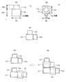
- FIG. 1 It is a basic diagram which shows the structure of the conventional 1 unit block.
- (A) is a side view
- (B) is a top view
- (C) is a 1 unit block with side wall protrusions
- (D) is a 1 unit block with side wall protrusions
- (E) is an assembly description of a 1 unit block with side wall protrusions. It is.
- (A) is a perspective view
- (B) is a top view
- (C) is a side view
- (D) is a cross-sectional view
- (E) is a bottom view.
- (A) is a perspective view
- (B) is a top view
- (C) is a side view (1)
- (D) is a side view (2)
- (E) is a bottom view.
- (A) is a perspective view
- (B) is a top view.
- (A) is a perspective view
- (B) is a top view.
- (A) is a perspective view
- (B) is a top view
- (C) is a side view
- (D) is a front view
- (E) is a bottom view.
- (A) is a bottom view
- (B) is a cross-sectional view along AA ′
- (C) is a cross-sectional view along BB ′
- (D) is a view showing a state of fitting.
- (A) is a perspective view
- (B) is a top view
- (C) is a side view
- (D) is a front view
- (E) is a bottom view.
- (A) is a perspective view of an 8 unit block with side wall projections
- (B) is a top view of an 8 unit block with side wall projections
- (C) is a perspective view of a 4 unit block with side wall projections
- (D) is 4 with side wall projections.
- It is a top view of a unit block.
- (A) is a perspective view
- (B) is a side view
- (C) is a top view showing a side wall hole.
- (A) is a perspective view
- (B) is a top view.
- (A) is a top view
- (B) is a bottom view (1)
- (C) is a bottom view (2)
- (D) is a bottom view (3).
- (A) is a bottom view
- (B) is an AA ′ sectional view
- (C) is an enlarged sectional view of a sidewall bottom surface.
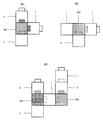
- (A) is the figure which showed the mode of fitting
- (B) is the enlarged view (1) which showed the mode of fitting
- (C) is the enlarged view (2) which showed the mode of fitting.
- (A) is a BB ′ sectional view
- (B) is an enlarged sectional view
- (C) is an enlarged sectional view of the bottom of the long wall.
- (A) is a bottom view
- (B) is an explanatory view of assembly
- (C) is a bottom view. It is a basic diagram which shows the structure of the 8 unit block by 3rd Embodiment.
- (A) is a bottom view
- (B) is a side view. It is a basic diagram which shows the structure of 8 unit block by other embodiment.
- the main body C3 is formed in a rectangular parallelepiped shape.
- the cylindrical protrusion C2 has a diameter Cd3 of 5.0 mm and a height Cd4 of 3.5 mm.
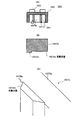
- FIG. 1C the case where the side wall cylindrical protrusion C2x is installed on the side wall C3B of the conventional one-unit block C1 will be described.
- another block (hereinafter referred to as another block) with respect to the side wall cylindrical protrusion C2x.
- a step is formed between the main body portions C3.
- the side wall cylindrical projections C2x come into contact with the side walls C3B of the main body C3, so that gaps are formed everywhere between the unit blocks C1.
- the side wall cylindrical protrusion C2x is fitted to the inside of the side wall C3B of the main body C3 of the other block. That is, the side wall C3B of the other block main body C3 hangs from the side wall cylindrical projection C2x. Therefore, if the side wall cylindrical projection C2x is simply reduced, the side wall cylindrical projection C2x cannot support the other block.
- the applicant of the present application can appropriately set the relationship between the diameter and height of the cylindrical protrusion and the wall thickness of the main body, thereby providing the side wall cylindrical protrusion even when the side wall cylindrical protrusion is provided on the side wall of the block.
- an example will be described.
- the toy blocks in the first to third forms are obtained by combining blocks of various units such as 1 unit block, 2 unit block, 4 unit block, 8 unit block, 16 unit block, 32 unit block and 64 unit block.
- the present invention is applied to each unit block.
- the unit of a block should just be a natural number, and there is no restriction
- the size tolerance is ⁇ 1.0%.
- the toy block may contain a deformed block whose shape is deformed in addition to these unit blocks.
- the unit blocks and the deformed blocks are collectively referred to as toy blocks.
- the toy blocks are preferably made of a highly elastic resin such as ABS (Acrylonitrile-Butadiene-ene Styrene Copolymer) resin or acrylic resin.
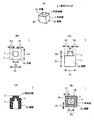
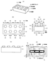
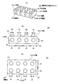
- FIG. 2 shows the configuration of one unit block in the present embodiment as a whole.
- each unit block has a rectangular parallelepiped body portion 3 as a whole and a cylindrical columnar protrusion 2 protruding from the top surface 3A of the body portion 3.
- the cylindrical protrusion 2 has a diameter D2 of 3.0 mm, which is 1/2 of the unit side length D1, and a protrusion height D4 of 1.5 mm, which is 1/2 of the diameter D2.
- the cylindrical protrusion 2 is rounded along the edge of the circle on the upper surface. Thereby, while a corner
- the bottom of the 1-unit block 1 is open. That is, the 1 unit block 1 consists of one top surface 3A and four side walls 3B, and the cylindrical projection 2 protrudes from the top surface 3A.
- the cylindrical protrusion 2 is provided at the center of the top surface 3A, and the distance D3 from the side wall 3B to the end of the cylindrical protrusion 2 is 1.5 mm.
- the protruding hole 6 may not be provided.
- the side wall 3B has a substantially uniform thickness as a whole, and its thickness T1 is 1.5 mm, which is a quarter of the unit side length D1.
- the inter-wall distance D5 in the horizontal direction of the fitting portion 5 (FIG. 2 (E)) is the same as 1/2 of the unit side length D1 in both the vertical and horizontal directions, that is, the diameter D2 of the cylindrical protrusion 2. Therefore, when the cylindrical projection 2 is inserted into the fitting portion 5, the main body portion 3 comes into contact with the cylindrical projection 2 at four points on the inner surface side of the side wall 3 ⁇ / b> B constituting the fitting portion 5 and holds the cylindrical projection 2. It becomes possible to do.
- the size of the fitting part 5 in the horizontal direction is 3.0 mm ⁇ 3.0 mm.
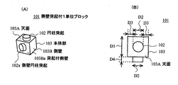
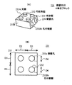
- FIG. 3 shows a one-unit block 101 with side wall protrusions.
- the one-unit block 101 with side wall protrusions has side wall columnar protrusions 102x having the same shape and the same size as the columnar protrusions 102 on the side wall 103Ba with protrusions, which is one of the four side walls 103B.
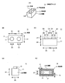
- the 1-unit block 101 with side wall projections can fit not only the columnar projections 102 on the top surface 103A but also the side wall columnar projections 102x to the fitting portions 5 of the other blocks, for a total of two other blocks. Can be held. That is, as shown in FIG. 4A, the one-unit block 101 with side wall projections can be assembled in two directions in the direction of the block that has been conventionally assembled only in the upward direction.
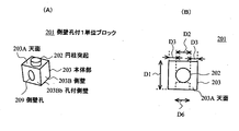
- FIG. 5 shows a one-unit block 201 with a side wall hole.
- the one-unit block 201 with a side wall hole has a side wall hole 209 connected to the space of the fitting portion 205 (not shown) on the side wall 203Bb with a hole, which is one of the four side walls 203B.
- the diameter D6 of the side wall hole 209 is appropriately selected depending on the material and wall thickness, but is substantially the same as the diameter D2, and is preferably ⁇ 3% of the diameter D2. In the present embodiment, the diameter D6 is 3.0 mm, which is the same as the diameter D2 of the cylindrical protrusion 102.
- the depth of the side wall hole 209 is the same as the wall thickness T1 (1.5 mm) of the side wall 203B.
- the 1-unit block 201 with a side wall hole can insert a cylindrical projection of another block not only into the fitting portion 205 (not shown) but also into the side wall hole 209. That is, as shown in FIG. 4B, the one-unit block 201 with a side wall hole can be assembled by changing the direction of the block that has been assembled only in one direction in a different direction.
- the direction of the cylindrical projection 2 is increased, The direction of the cylindrical protrusion 2 can be changed, and the degree of freedom in assembling the toy block can be significantly improved.
- the cylindrical protrusion 2 of the 1 unit block 1 inserted into the fitting portion 205 of the 1 unit block 201 with the side wall hole and the cylindrical protrusion 2 of the 1 unit block 1 inserted into the side wall hole 209 are not in contact with each other.
- the distance D3 is half ⁇ (unit side length D1 ⁇ diameter D2) / 2 ⁇ of the distance obtained by subtracting the diameter D2 of the cylindrical projection 2 from the unit side length D1, so that the projection height D4 ⁇ ⁇ (unit side length D1 ⁇ Diameter D2) / 2 ⁇ .
- the 1-unit block 101 with side wall protrusions supports the 1-unit block engaged in the horizontal direction.
- the side wall cylindrical protrusion 102x comes into linear contact with the inner surface side of the side wall 3B of the other block. For this reason, at first glance, by increasing the protrusion height D4 (see FIG. 2C) as much as possible, it is possible to increase the holding force of the one unit block engaged in the horizontal direction.
- the projection height D4 is increased, the diameter D2 must be decreased accordingly. If the diameter D2 is too small, the cylindrical protrusion 2 becomes needle-shaped, and there is a risk that it will stick into the hand. Further, if the diameter D2 is reduced, the wall thickness T1 must be increased, and a large amount of material is required.
- the cylindrical protrusion 2 does not become needle-like, and safety as a toy can be ensured. Moreover, in order to hold
- the wall thickness T1 can be relatively large. For this reason, even when a weight is applied from the side wall 3B to the cylindrical projection protruding in the horizontal direction by its own weight or the like, the side wall 3B is not deformed, and other blocks can be appropriately held.
- the wall thickness T1 is more preferably less than 0.55.
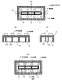
- the 2-unit block 11 has an external shape in which two 1-unit blocks 1 are connected.
- the 2 unit block 11 has a rectangular parallelepiped main body 13 and two cylindrical protrusions 12.
- the cylindrical protrusion 12 has the same shape as the cylindrical protrusion 2 of the one unit block 1.
- the main body 13 has a size obtained by combining two unit sizes, one side in the horizontal direction and the height are equal to the unit side length D1, and the other side in the horizontal direction is twice the unit side length D1.
- length ⁇ width ⁇ height 6.0 mm ⁇ 12.0 mm ⁇ 6.0 mm
- wall thickness T1 1.5 mm
- distance D3 1.5 mm.
- the 2 unit block 11 has a fitting portion 15 constituted by the inner side surfaces of the four side walls 13B. Specifically, the size of the fitting portion 15 in the horizontal direction is 3.0 mm ⁇ 9.0 mm.
- the cylindrical protrusion of the other block when the cylindrical protrusion of the other block is inserted, the cylindrical protrusion and the side wall 13B come into contact at three points to hold the other block.
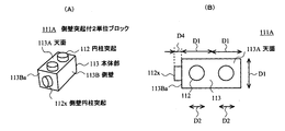
- the side wall cylindrical protrusion 112x is provided on the side wall 113Ba with protrusions having the short side in the horizontal direction among the four side walls 113B.
- the shape of the side wall cylindrical projection 112 x is the same as that of the cylindrical projection 12.
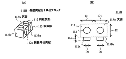
- the two-unit block 111B with side wall projections is provided with two side wall columnar projections 112x on the side wall with projection 113Ba having a long side in the horizontal direction among the four side walls 113B.
- the 2 unit blocks 211A and 211B with a side wall hole are the side walls with a hole which has a horizontal short side or a long side among the four side walls 213B similarly to the 2 unit block 111A and 111B with a side wall protrusion.
- Side wall holes 219 are provided in 213Bb. The shape of the side wall hole 219 is the same as that of the side wall hole 209 of the one unit block 201.
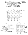
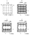
- the 8-unit block 21 has an outer shape in which eight 1-unit blocks 1 are connected.
- the 8-unit block 21 has a rectangular parallelepiped main body 23 and eight cylindrical protrusions 22.
- the cylindrical protrusion 22 has the same shape as the cylindrical protrusion 2 of the one unit block 1.
- the main body 23 has a size obtained by combining eight unit sizes, one side in the horizontal direction is twice the unit side length D1, and the other side in the horizontal direction is four times the unit side length D1.
- length ⁇ width ⁇ height 12.0 mm ⁇ 24.0 mm ⁇ 6.0 mm
- wall thickness T1 1.5 mm
- distance D3 1.5 mm.
- the 8-unit block 21 has a fitting portion 25 constituted by the inner surfaces of the four side walls 23B.
- the horizontal size of the fitting portion 25 is 21.0 mm ⁇ 9.0 mm.
- An intermediate partition 27 that forms the fitting portion 25 together with the side wall 23 ⁇ / b> B is formed on the fitting portion 25 on the longitudinal center line.
- the intermediate partition 27 is slightly shorter in the height direction than the side wall 23B, thereby facilitating insertion of the cylindrical protrusion.
- the intermediate partition 27 includes two long walls 27A in the longitudinal direction and four short walls 27B that are orthogonal to the long walls 27A and connect the two long walls 27A.
- FIG. 10D in the 8-unit block 21, when the cylindrical protrusions of the other blocks are inserted, the four cylindrical protrusions located at the longitudinal ends and the side wall 23B come into contact with each other at three points. Hold the block. On the other hand, the four cylindrical projections located in the longitudinal direction and the side wall 23B come into contact at two points to hold the other blocks.
- the short wall 27B is provided at a portion where the columnar protrusion of the other block and the long wall 27A are in contact with each other, and the long wall 27A is prevented from being deformed by a load from the columnar protrusion. That is, the intermediate partition 27 has a shape in which three squares are connected, so that the strength of the intermediate partition 27 is maintained while reducing the amount of material used.
- the long wall 27A may protrude longer than the short wall 27B.
- the 4-unit block 31 has an outer shape in which four 1-unit blocks 1 are connected.
- the four unit block 31 has a rectangular parallelepiped main body 33 and four cylindrical protrusions 32.
- the cylindrical protrusion 32 has the same shape as the cylindrical protrusion 2 of the one unit block 1.
- the main body 33 has a horizontal side twice the unit side length D1.
- the 4-unit block 31 has an intermediate partition 37 inside a fitting portion 35 constituted by the inner surfaces of the four side walls 33B.
- the length of the intermediate partition 37 in the height direction is the same as that of the intermediate partition 27 of the 8-unit block 21.
- the intermediate partition 37 has a square shape, but may have a square shape like the intermediate partition 27.
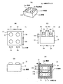
- the eight unit block 121 with side wall projections is provided with four side wall cylindrical projections 122x on the side wall with projection 123Ba having a long side in the horizontal direction among the four side walls 123B.
- the shape of the side wall cylindrical protrusion 122x is the same as that of the cylindrical protrusion 12.
- two side wall cylindrical protrusions 122x may be provided on the side wall 123Ba with protrusions having the short side in the horizontal direction among the four side walls 123B.
- two side wall columnar protrusions 132a can be provided on any side wall 133Ba with protrusions.
- the 8 unit block 221 with a side wall hole is 4 to the side wall 223Bb with a hole which has a horizontal long side among four side walls 3B similarly to the 8 unit block 121 with a side wall protrusion.
- Two side wall holes 229 are provided.
- the shape of the side wall hole 229 is the same as the side wall hole 209 of the one unit block 201.
- two side wall holes 229 may be provided on the side wall 223Bb having a short side in the horizontal direction among the four side walls 223B.
- the four-unit block 231 with a side wall hole is similar to the four-unit block 131 with a side wall projection in the side wall with a hole 233Bb, which is one side in the horizontal direction, of the four side walls 233B. 239 is provided.
- the shape of the side wall hole 239 is the same as the side wall hole 209 of the one unit block 201.
- side wall columnar protrusions may be formed on two or more of the side walls, but are preferably formed only on one side. This is because if the side wall cylindrical projections are formed on a plurality of surfaces, the configuration as a toy block cannot be simplified.
- the side wall hole may be formed on two or more of the side walls, but is preferably formed on only one. This is because the appearance of the toy block is maintained when the unused side wall holes are not exposed to the outside.
- the 16 unit block 51 has an outer shape in which 16 1 unit blocks 1 are connected.
- the 16 unit block 51 has a rectangular parallelepiped main body 53 and 16 cylindrical protrusions 52.
- the cylindrical protrusion 52 has the same shape as the cylindrical protrusion 2 of the one unit block 1.
- an intermediate partition 57X may be provided for each row as a part of the fitting portion 55, or an intermediate partition 57Y may be partially provided as shown in FIG. good.
- the long wall 57A may be constituted by only one sheet as the intermediate partition 57Z.
- the configuration of these intermediate partitions 57 can be applied to any number of blocks such as 4, 8, 32 units.
- the main body 3 of the 1 unit block 1 of the present invention has a 1 ⁇ 1 ⁇ 1 cube as 1 unit size, that is, 1 unit block 1. And has a rectangular parallelepiped shape in which one or a plurality of 1 unit sizes are combined, and an opening surface that opens is a bottom surface, and includes four side walls 3B and a top surface 3A.
- the cylindrical protrusion 2 has a cylindrical shape, is provided on one or more outer surfaces of the top surface 3A or the side wall 3B, and has a diameter D2 of 0.4 or more and less than 0.6 with respect to the unit side length D1. Is (1 ⁇ diameter) ⁇ (0.4 or more and 0.5 or less).
- the fitting portion 5 is surrounded by four side walls 3B, and is brought into contact with another cylindrical projection X2 having the same shape as the cylindrical projection 2 with at least one of the side walls 3B, thereby fitting the other cylinder.
- the protrusion X2 is held.
- the wall thickness T1 in the vicinity of the bottom surface of the wall side wall 3B that contacts and holds the other cylindrical protrusion X2 in the fitting portion is expressed by (1 ⁇ diameter) ⁇ 0.5 + ⁇ , and ⁇ 0.05 ⁇ ⁇ ⁇ . 0.03, more preferably ⁇ 0.02 ⁇ ⁇ ⁇ 0.01. In other words, the wall thickness T1 is approximately (1 ⁇ diameter) ⁇ 0.5.
- ⁇ occurs, for example, when the dimensions of the main body in each unit block are uniformly reduced from each unit size, or when the inter-wall distance D5 is designed to be smaller than the diameter D2, and in this embodiment ⁇ Is zero.
- the other unit cylinder 1 is restricted to project the cylindrical projection 2 in the vertical and vertical directions.
- the size of the projection X2 is small, the other cylindrical projection X2 can be firmly held by the balance of the diameter D2 and the height D4 of the other cylindrical projection X2 and the holding force due to the thickness of the wall thickness T1.
- the cylindrical protrusion 2 has a diameter of 0.45 or more and less than 0.55, and a height of (1 ⁇ diameter) ⁇ (0.45 or more and 0.5 or less). Thereby, the 1 unit block 1 can hold
- the rectangular parallelepiped shape of the main body portion 23 is a shape in which unit sizes of at least 2 ⁇ 2 or more are combined, and the fitting portion 25 is brought into contact with another cylindrical protrusion X2 in the fitting portion surrounded by the four side walls 23B.
- An intermediate partition 27 is provided. Thereby, even if it is a unit block like the 8 unit block 21 which has 2 or more rows of cylindrical protrusions 22 in a transversal direction, other cylindrical protrusion X2 can be hold
- the one-unit block 101 with side wall protrusions is provided with a side wall cylindrical protrusion 102x having substantially the same size as the cylindrical protrusion 102 on at least one of the four side walls 103B.
- the 1-unit block 101 with a side wall protrusion can assemble not only a vertical direction but another block also in a horizontal direction, and can improve the freedom degree of an assembly.
- the one-unit block 201 with a side wall hole is provided with a side wall hole 209 having substantially the same size as the cylindrical protrusion 202 on at least one of the four side walls 203B.
- the 1-unit block 201 with a side wall hole can deflect
- FIGS. 16 to 18 show a second embodiment.
- the first embodiment shown in FIGS. 2 to 15 is based on the point that a step is provided inside the side wall 1023B and the configuration of the intermediate partition 1027. This is different from the embodiment.
- a description will be given with reference numerals obtained by adding 1000 to locations corresponding to the first embodiment.
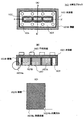
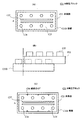
- the side wall 1023B is formed inside the side wall bottom surface 1023Ba, which is the bottom surface, by cutting out the inner side surface of the side wall 1023B and the corners of the side wall bottom surface 1023Ba, and has a rectangular cross section. It has an inner recess 1023Bb in shape.
- the inner recess 1023Bb is provided along the inside of the four side wall bottom surfaces 1023Ba surrounding the fitting portion 1025, and one side is 0.1 to 0.3 mm.
- a cross section may be a notch of triangular shape or circular arc shape.
- the long wall 1027A of the intermediate partition 1027 has an outer convex portion 1027Ab that bulges outward in each region where the cylindrical protrusion X2 of the other block is not fitted.
- a fitting recess 1027Ac is formed in which only the region where the projection X2 is fitted is recessed.
- an extended line extending in parallel to the long wall 1027A from a region where the distance from the side wall 1023B is the longest in the long wall 1027A (that is, the most recessed portion in the fitting recess 1027Ac) is defined as a boundary line 1027Aa.
- the inter-wall distance D11 from the boundary line 1027Aa to the inner surface of the side wall 1023B is slightly smaller than the diameter D2 (3.0 mm) of the cylindrical protrusion 1022 (for example, 2.7 to 2.9 mm).
- the outer protrusion 1027Ab protrudes from the boundary line 1027Aa by about 0.5 mm to 2.0 mm at the maximum protruding portion.
- the entrance distance D12 from the intersection of the inner recess 1023Ba with the side wall bottom surface 1023Ba (FIG. 16C) to the boundary line 1027Aa (FIG. 17B) is the same as or slightly larger than the diameter D2 (for example, (3.0 to 3.1 mm).
- the outer convex portion 1027Ab is formed so as to slightly protrude (for example, 0.1 to 0.3 mm) from the region inside the boundary line 1027Aa of the long wall 1027A, and the tip thereof is the side wall bottom surface. It is formed at the same position as 1023Ba or slightly inside (for example, 0.0 mm to 0.1 mm inside).
- the cylindrical protrusion X2 of the other block is between the side wall 1023B and the outer protrusion 1027Ab that protrude most on the bottom surface of the 8-unit block 1021. It will be inserted naturally.
- the distance D13 (FIG. 17B) between the outer protrusion 1027Ab and the side wall bottom surface 1023Ba is formed smaller than the diameter D2 of the cylindrical protrusion X2.
- the columnar projection X2 naturally fits in the fitting recess 1027Ac and is guided to an appropriate position in the fitting portion 1025.
- the cylindrical projection X2 once stays in the inner recess 1023Ba, since the step is small, it is easily inserted into the inner recess 1023Bb by the user's pushing operation. Since the inter-wall distance D11 is smaller than the diameter D2 of the cylindrical protrusion X2, the side wall 1023B always presses the column protrusion X2 and is firmly held.
- the wall thickness T1 is designed to be sufficiently thick, the possibility that the side wall 1023B is plastically deformed is small. Further, in the intermediate partition 1027, the risk of plastic deformation is small due to the short wall 1027B provided at the portion where the cylindrical protrusion X2 contacts.
- the fitting recess 1027Ac is a trapezoidal recess, and the trapezoidal leg has a gentler slope than the arc of the cylindrical protrusion X2. For this reason, fitting recessed part 1027Ac can contact the cylindrical protrusion X2 only at the most recessed one point (one line), and can hold
- the fitting recess 1027Ac has a contact other than the contact W when the cylindrical protrusion X2 moves to the left and right.
- the fitting recess 1027Ac Prior to contact of the location with the fitting recess 1027Ac, the fitting recess 1027Ac starts to be inclined, and the distance between the fitting recess 1027Ac and the side wall 1023B is reduced. For this reason, the cylindrical protrusion X2 cannot substantially move to the left and right, and the contact point with the fitting recess 1027Ac remains one point.
- the fitting recess 1027Ac may have a rounded trapezoidal corner or an arc shape. It is sufficient that the inclined portion is gentler than the circular arc of the cylindrical protrusion X2.
- the boundary line 1027Aa which is the position where the other cylindrical protrusion X2 contacts, is the most concave on at least one surface of the long wall 1027A, and the outer convex portion 1027Ab acting as a guide mechanism To have.
- the 8-unit block 1021 does not increase the contact point between the other cylindrical protrusion X2 and the long wall 1027A, and the other cylindrical protrusion X2 does not shift in the horizontal direction, and the other unit block with which the 8-unit block 1021 is fitted.
- the holding force can be kept moderate, and the holding force can be prevented from becoming excessive as the number of the cylindrical protrusions 1022 increases.
- the inter-wall distance D11 from the side wall 1023B to which one other cylindrical protrusion is to be fitted to the long wall 1027A is formed to be slightly smaller than the diameter D2 of the cylindrical protrusion 1022. Thereby, it can cancel that the height of the cylindrical protrusion 1022 is small and the contact area with the fitting portion 1025 is small, and the other blocks can be securely held.
- the inter-wall distance D5 between the two side walls is formed slightly smaller than the diameter D2 of the cylindrical protrusion 1022.
- FIGS. 20 to 21 show a third embodiment.
- FIGS. 16 to 18 show that the wall thickness T1 and the size of the cylindrical protrusion 2022 and that the intermediate partition 2027 does not have a short wall. This is different from the second embodiment.
- a description will be given with reference numerals obtained by adding 1000 to portions corresponding to those in the second embodiment.
- a linear guide that is a linear convex portion is provided inside the side wall C23B.
- the cylindrical protrusion CX22 stops its movement by coming into contact with the linear guide C00, the number of contact points of the cylindrical protrusion CX22 increases, and a large force is required for removal.
- the linear guide C00 is made small so as not to contact the cylindrical protrusion CX22, the displacement of the cylindrical protrusion CX22 cannot be completely prevented.
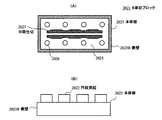
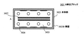
- the 8-unit block 2021 of the present embodiment applies the intermediate partition 1027 of the second embodiment to the 8-unit block 2021 having the same configuration as the conventional unit block C21.
- the cylindrical projection C2 is formed such that the diameter Cd3 is 5.0 mm, the height Cd4 is 3.5 mm, and the wall thickness of the side wall 2023B is 1.5 mm.
- the intermediate partition 2027 is composed of only two long walls 2027A and does not have a short wall.
- plastic deformation can be prevented even without a short wall by using a relatively flexible resin such as polypropylene resin or styrene resin.
- the cylindrical protrusion 20X2 of the other block can be prevented from moving in the parallel direction to the intermediate partition 2027.
- it is effective to apply the intermediate partition 2027 to a unit block in which the diameter D2 of the cylindrical protrusion 2022 that is likely to be displaced in the horizontal direction is 0.4 or more and less than 0.8.
- the wall thickness T1 in the vicinity of the bottom surface of the side wall 2023B is approximately (1-diameter ) ⁇ 0.5 + ⁇ , and ⁇ 0.05 ⁇ ⁇ ⁇ 0.03.
- the 8-unit block 2021 is provided with an outer convex portion 2023Bb as a guide mechanism on at least one surface of the side wall 2023B and the long wall 2027A constituting the fitting portion 2025.
- the 8-unit block 2021 can appropriately maintain the holding force with the other unit blocks fitted without the other cylindrical protrusions 20X2 being displaced in the horizontal direction, and the number of the cylindrical protrusions 2022 increases. An excessive holding force can be prevented.
- outer side convex part 1027Ab was provided in 8 unit block 1021 .
- the present invention is not limited to this, and the outer convex portion 1027Ab can be applied to all blocks in which the cylindrical protrusions are in two or more rows, such as 4, 6, 10, 12, 16,.
- the outer convex portion 2027Ab can be applied to various number of unit blocks.
- the present invention is not limited to this, and the same effect can be obtained when applied to each unit block in the first and third embodiments.
- the same effect can be obtained even if the outer convex portion 1027Ab is provided inside the side wall 1023B.
- the unit size is 8.0 ⁇ 8.0 ⁇ 6.0 mm.
- the present invention is not limited to this, and the present invention can be applied to other unit blocks of various sizes.
- the present invention can be used for various toy blocks that can be assembled.
- 1 ... 1 unit block, 2, 12, 22, 32, 52, 102, 202, 1022 ... cylindrical protrusion, 3, 13, 23, 33, 53, 103, 203, 1023 ... main body, 3B, 13B , 23B, 33B, 53B, 103B, 203B, 1023B > side wall, 3A, 13A, 23A, 33A, 53A, 103A, 203A, 1023A ... top, T1 ... wall thickness, D1 ... unit side length, D2 ... Diameter, D5 ... Distance between walls.
Landscapes
- Toys (AREA)
Description
図1(C)に示すように、通常の玩具用のブロックでは、本体部C3が直方体形状に形成されている。例えば、ダイアブロック(登録商標)のような従来型の玩具用ブロックの場合、1単位ブロックC1の本体部C3は、縦×横×高さ=Cd1×Cd1×Cd2=4×4×3(具体的には8.0×8.0×6.0mm)に形成されており、このサイズを1単位サイズとする。この円柱突起C2は、直径Cd3が5.0mm、高さCd4が3.5mmに形成されている。
図16~18は、第2の実施の形態を示すものであり、側壁1023Bの内側に段差が設けられている点と、中間仕切1027の構成とが、図2~図15に示す第1の実施の形態とは異なっている。なお、第2の実施の形態においては、第1の実施の形態と対応する箇所に1000を加算した符号を附して説明する。
図20~図21は、第3の実施の形態を示すものであり、壁厚T1及び円柱突起2022のサイズと、中間仕切2027が短壁を有さない点が、図16~図18に示した第2の実施の形態と異なっている。なお、第3の実施の形態においては、第2の実施の形態と対応する箇所に1000を加算した符号を附して説明する。
なお、上述した第2の実施の形態によれば、8単位ブロック1021に外側凸部1027Abを設けるようにした場合について述べた。本発明はこれに限らず、4、6、10、12、16・・・・のように、円柱突起が2列以上になる全てのブロックに対して外側凸部1027Abを適用することができる。第3の実施の形態においても同様であり、種々の数でなる単位ブロックに対して外側凸部2027Abを適用することができる。
Claims (8)
- 単位辺長を1としたとき、1×1×1で表される立方体を1単位サイズとし、ほぼ1又は複数の前記単位サイズが結合したサイズの直方体形状を有し、開口する開口面を底面とし、4つの側壁と天面とから構成される本体部と、
前記天面又は前記側壁のうち一以上の外面に設けられ、前記単位辺長に対して、直径が0.4以上0.6未満であり、高さが(1-前記直径)×(0.4以上0.5以下)である円柱形状の円柱突起とを有し、
前記本体部は、
前記4つの側壁に囲まれ、前記円柱突起と同一形状である他の円柱突起を接触させて嵌合させることにより、当該他の円柱突起を保持する嵌合部を有し、
前記側壁の底面近傍の壁厚が、
(1-前記直径)×0.5+αで表され、
-0.05≦α≦0.03である
ことを特徴とする玩具用ブロック。 - 前記円柱突起は、直径が0.45以上0.55未満であり、高さが(1-前記直径)×(0.45以上0.5以下)である
ことを特徴とする請求項1に記載の玩具用ブロック。 - 前記直方体形状は、
少なくとも2×2以上の前記単位サイズが結合したサイズでなり、
前記嵌合部は、
前記4つの側壁に囲まれた嵌合部において、前記他の円柱突起に接触させる長壁を有する
ことを特徴とする請求項2に記載の玩具用ブロック。 - 前記4つの側壁の少なくとも一つに、前記円柱突起とほぼ同一サイズの側壁円柱突起が設けられている
ことを特徴とする請求項1に記載の玩具用ブロック。 - 前記4つの側壁の少なくとも一つに、前記円柱突起とほぼ同一サイズの側壁孔が設けられている
ことを特徴とする請求項1に記載の玩具用ブロック。 - 一つの前記他の円柱突起が嵌合されるべき2つの側壁間又は側壁から前記長壁までの壁間距離が、前記円柱突起の直径よりも僅かに小さく形成されている
ことを特徴とする請求項3に記載の玩具用ブロック。 - 前記長壁の少なくとも一面には、前記他の円柱突起が接触する位置が最も凹んだガイド機構を有する
ことを特徴とする請求項1に記載の玩具用ブロック。 - 単位辺長を1としたとき、1×1×xで表される直方体を1単位サイズとし、1又は複数の前記単位サイズが結合した直方体形状を有し、開口する開口面を底面とし、4つの側壁と天面とから構成される本体部と、
前記天面又は前記側壁のうち一以上の外面に設けられ、上記単位辺長に対して、直径が0.4以上0.8未満である円柱形状の円柱突起とを有し、
前記本体部は、
前記4つの側壁に囲まれ、前記円柱突起と同一形状である他の円柱突起を接触させて嵌合させることにより、当該他の円柱突起を保持する嵌合部を有し、
前記側壁の底面近傍の壁厚が、
(1-前記直径)×0.5+αで表され、
-0.05≦α≦0.03であり、
前記嵌合部を構成する壁のうち少なくとも一面には、前記他の円柱突起が接触すべき接触位置が最も凹み、当該他の円柱突起が当該接触位置から移動しても、当該接触した円柱突起の接触ポイント以外の箇所が接触しないような傾斜が設けられたガイド機構を有する
ことを特徴とする玩具用ブロック。
Priority Applications (5)
| Application Number | Priority Date | Filing Date | Title |
|---|---|---|---|
| EP12878811.4A EP2835162A4 (en) | 2012-06-13 | 2012-12-15 | CONSTRUCTION GAME |
| HK15105807.5A HK1205038B (en) | 2012-06-13 | 2012-12-15 | Toy block |
| US14/407,030 US9849398B2 (en) | 2012-06-13 | 2012-12-15 | Toy block |
| CN201280073662.0A CN104487146B (zh) | 2012-06-13 | 2012-12-15 | 玩具用组件 |
| JP2014521199A JP6158803B2 (ja) | 2012-06-13 | 2012-12-15 | 玩具用ブロック |
Applications Claiming Priority (2)
| Application Number | Priority Date | Filing Date | Title |
|---|---|---|---|
| JP2012134281 | 2012-06-13 | ||
| JP2012-134281 | 2012-06-13 |
Publications (1)
| Publication Number | Publication Date |
|---|---|
| WO2013186955A1 true WO2013186955A1 (ja) | 2013-12-19 |
Family
ID=49757811
Family Applications (1)
| Application Number | Title | Priority Date | Filing Date |
|---|---|---|---|
| PCT/JP2012/082585 Ceased WO2013186955A1 (ja) | 2012-06-13 | 2012-12-15 | 玩具用ブロック |
Country Status (6)
| Country | Link |
|---|---|
| US (1) | US9849398B2 (ja) |
| EP (1) | EP2835162A4 (ja) |
| JP (1) | JP6158803B2 (ja) |
| CN (1) | CN104487146B (ja) |
| TW (1) | TWI576142B (ja) |
| WO (1) | WO2013186955A1 (ja) |
Families Citing this family (10)
| Publication number | Priority date | Publication date | Assignee | Title |
|---|---|---|---|---|
| US9345982B2 (en) | 2014-09-01 | 2016-05-24 | Joseph Farco | Building block universal joint system |
| US10232279B2 (en) * | 2015-12-18 | 2019-03-19 | Reginald Frederick Woolston | Modular cube building system |
| KR101758781B1 (ko) | 2016-01-25 | 2017-07-17 | (주)버블블록 | 조립식 블록 기초판 및 조립식 블록 기초판 조립체 |
| USD834104S1 (en) | 2017-04-26 | 2018-11-20 | Mattel-Mega Holdings (Us), Llc | Construction set element |
| USD834105S1 (en) | 2017-06-01 | 2018-11-20 | Mattel-Mega Holdings (Us), Llc | Construction set element |
| US10518189B2 (en) * | 2017-09-20 | 2019-12-31 | Mattel-Mega Holdings (Us), Llc | Tool for use with toy construction elements |
| DK3706880T3 (da) * | 2017-11-08 | 2022-03-14 | Lego As | Legetøjsbyggesæt |
| US11964883B2 (en) * | 2020-08-06 | 2024-04-23 | Jonathan Hendrik Van Ee | Gigacubes solar still |
| US11565192B2 (en) * | 2020-08-06 | 2023-01-31 | Jonathan Hendrik Van Ee | Letter cubes |
| US12594509B2 (en) | 2023-08-19 | 2026-04-07 | Farco ToyCo LLC | Interconnecting methods and systems for posable bendable building block toys |
Citations (3)
| Publication number | Priority date | Publication date | Assignee | Title |
|---|---|---|---|---|
| JPH05277262A (ja) * | 1992-03-30 | 1993-10-26 | Tanishita Kogyo Kk | 組立ブロックセット |
| JPH10506309A (ja) | 1994-09-29 | 1998-06-23 | レゴ エー/エス | 積み重ね自在ブロックシステム |
| JP2010172568A (ja) * | 2009-01-30 | 2010-08-12 | Kawada Co Ltd | ブロック玩具 |
Family Cites Families (19)
| Publication number | Priority date | Publication date | Assignee | Title |
|---|---|---|---|---|
| US3162973A (en) * | 1961-06-27 | 1964-12-29 | Interlego Ag | Toy building element |
| GB1008459A (en) * | 1962-06-09 | 1965-10-27 | Hasel Heinz | Hollow box-shaped toy building elements |
| DE1478447B1 (de) * | 1963-07-26 | 1970-02-12 | Hoewe August W | Baukastenspiel |
| FR1415559A (fr) | 1964-06-29 | 1965-10-29 | Le Jouet Francais | éléments perfectionnés pour jeux de construction |
| JPS4511321Y1 (ja) * | 1967-11-18 | 1970-05-20 | ||
| CH495762A (de) | 1968-06-05 | 1970-09-15 | Bartoeck Minnaard Maatje | Bausatz-Spielzeug |
| CA1046767A (en) * | 1975-11-19 | 1979-01-23 | Altro, Stephen | Interlocking toy building element |
| JPS5415759Y2 (ja) | 1975-11-21 | 1979-06-23 | ||
| GB1585436A (en) * | 1978-04-15 | 1981-03-04 | Lin Wen Pin | Building blocks |
| GB2118447B (en) | 1982-04-14 | 1985-10-23 | Kassai Kk | Block toy |
| US4744780A (en) * | 1986-02-06 | 1988-05-17 | Tyco Industries, Inc. | Adapter block |
| IT1257727B (it) | 1992-11-03 | 1996-02-13 | Struttura di mattonella, particolarmente per l'edilizia | |
| IL121303A0 (en) * | 1997-07-14 | 1998-01-04 | Reisman Ron | Toy building blocks |
| TW436310B (en) * | 1999-01-15 | 2001-05-28 | Interlego Ag | A building element for a toy building set |
| US8105128B1 (en) * | 2006-02-10 | 2012-01-31 | Soerensen Soeren Christian | Injection molded toy building element |
| CN2870929Y (zh) * | 2006-03-01 | 2007-02-21 | 马达伟 | 一种智力玩具 |
| DE202011109611U1 (de) * | 2011-12-27 | 2012-03-15 | Shiarn Fur Industry Co., Ltd. | Baustein |
| US8771032B2 (en) * | 2012-03-23 | 2014-07-08 | Delsun Co., Ltd. | Block assembly |
| US20140220854A1 (en) * | 2013-02-07 | 2014-08-07 | Yang-Chih Lee | Adaptor brick |
-
2012
- 2012-12-15 WO PCT/JP2012/082585 patent/WO2013186955A1/ja not_active Ceased
- 2012-12-15 US US14/407,030 patent/US9849398B2/en active Active
- 2012-12-15 JP JP2014521199A patent/JP6158803B2/ja active Active
- 2012-12-15 CN CN201280073662.0A patent/CN104487146B/zh active Active
- 2012-12-15 EP EP12878811.4A patent/EP2835162A4/en not_active Withdrawn
-
2013
- 2013-01-29 TW TW102103337A patent/TWI576142B/zh not_active IP Right Cessation
Patent Citations (3)
| Publication number | Priority date | Publication date | Assignee | Title |
|---|---|---|---|---|
| JPH05277262A (ja) * | 1992-03-30 | 1993-10-26 | Tanishita Kogyo Kk | 組立ブロックセット |
| JPH10506309A (ja) | 1994-09-29 | 1998-06-23 | レゴ エー/エス | 積み重ね自在ブロックシステム |
| JP2010172568A (ja) * | 2009-01-30 | 2010-08-12 | Kawada Co Ltd | ブロック玩具 |
Non-Patent Citations (1)
| Title |
|---|
| See also references of EP2835162A4 |
Also Published As
| Publication number | Publication date |
|---|---|
| EP2835162A1 (en) | 2015-02-11 |
| US9849398B2 (en) | 2017-12-26 |
| EP2835162A4 (en) | 2016-03-16 |
| HK1205038A1 (zh) | 2015-12-11 |
| CN104487146B (zh) | 2016-06-29 |
| TWI576142B (zh) | 2017-04-01 |
| US20150174502A1 (en) | 2015-06-25 |
| JP6158803B2 (ja) | 2017-07-05 |
| JPWO2013186955A1 (ja) | 2016-02-01 |
| TW201404445A (zh) | 2014-02-01 |
| CN104487146A (zh) | 2015-04-01 |
Similar Documents
| Publication | Publication Date | Title |
|---|---|---|
| JP6158803B2 (ja) | 玩具用ブロック | |
| ES2317318T3 (es) | Conector enchufable para placas de circuito impreso. | |
| CA2782755C (en) | Jigsaw puzzle having one or more puzzle pieces that can be bent | |
| JP2011520580A5 (ja) | ||
| JP3194309U (ja) | リニアガイド | |
| JP2006068522A (ja) | おもちゃ組立ブロック | |
| JP2013129449A (ja) | 中仕切り容器 | |
| HK1205038B (en) | Toy block | |
| JP6727433B2 (ja) | 梱包装置 | |
| JP6018371B2 (ja) | 板材を使用した収納ラック | |
| WO2013129391A1 (ja) | 化粧料容器 | |
| JP3161490U (ja) | 梱包箱用緩衝材 | |
| KR20120104052A (ko) | 슬라이드 적층형 수납용기의 적층구조 및 적층보관장치 | |
| JP3175375U (ja) | 組み合わせ式積木 | |
| JP3174085U (ja) | 仕切体 | |
| JP7356792B2 (ja) | 仕切り部材 | |
| JP3178322U (ja) | ティッシュペーパー収納箱 | |
| JP3195842U (ja) | 情報コンセント | |
| JP2023154973A (ja) | ブロック玩具 | |
| JP7179253B2 (ja) | まな板の構造 | |
| JP4891611B2 (ja) | 化粧料容器 | |
| KR200377910Y1 (ko) | 수납체용 칸막이판 | |
| KR20130080567A (ko) | 다양한 크기의 서랍을 다양한 방식으로 수납할 수 있는 서랍장 | |
| KR100920366B1 (ko) | 서적 케이스 및 그 제조 방법 | |
| JP2007029156A (ja) | 収納棚の補強構造 |
Legal Events
| Date | Code | Title | Description |
|---|---|---|---|
| 121 | Ep: the epo has been informed by wipo that ep was designated in this application |
Ref document number: 12878811 Country of ref document: EP Kind code of ref document: A1 |
|
| WWE | Wipo information: entry into national phase |
Ref document number: 2012878811 Country of ref document: EP |
|
| ENP | Entry into the national phase |
Ref document number: 2014521199 Country of ref document: JP Kind code of ref document: A |
|
| WWE | Wipo information: entry into national phase |
Ref document number: 14407030 Country of ref document: US |
|
| NENP | Non-entry into the national phase |
Ref country code: DE |