WO2013187128A1 - ウォーターサーバー - Google Patents
ウォーターサーバー Download PDFInfo
- Publication number
- WO2013187128A1 WO2013187128A1 PCT/JP2013/061906 JP2013061906W WO2013187128A1 WO 2013187128 A1 WO2013187128 A1 WO 2013187128A1 JP 2013061906 W JP2013061906 W JP 2013061906W WO 2013187128 A1 WO2013187128 A1 WO 2013187128A1
- Authority
- WO
- WIPO (PCT)
- Prior art keywords
- axle
- drawer
- height
- raw water
- front side
- Prior art date
- Legal status (The legal status is an assumption and is not a legal conclusion. Google has not performed a legal analysis and makes no representation as to the accuracy of the status listed.)
- Ceased
Links
Images


Classifications
-
- B—PERFORMING OPERATIONS; TRANSPORTING
- B60—VEHICLES IN GENERAL
- B60P—VEHICLES ADAPTED FOR LOAD TRANSPORTATION OR TO TRANSPORT, TO CARRY, OR TO COMPRISE SPECIAL LOADS OR OBJECTS
- B60P3/00—Vehicles adapted to transport, to carry or to comprise special loads or objects
- B60P3/22—Tank vehicles
- B60P3/224—Tank vehicles comprising auxiliary devices, e.g. for unloading or level indicating
-
- A—HUMAN NECESSITIES
- A47—FURNITURE; DOMESTIC ARTICLES OR APPLIANCES; COFFEE MILLS; SPICE MILLS; SUCTION CLEANERS IN GENERAL
- A47B—TABLES; DESKS; OFFICE FURNITURE; CABINETS; DRAWERS; GENERAL DETAILS OF FURNITURE
- A47B69/00—Cocktail cabinets
-
- A—HUMAN NECESSITIES
- A47—FURNITURE; DOMESTIC ARTICLES OR APPLIANCES; COFFEE MILLS; SPICE MILLS; SUCTION CLEANERS IN GENERAL
- A47B—TABLES; DESKS; OFFICE FURNITURE; CABINETS; DRAWERS; GENERAL DETAILS OF FURNITURE
- A47B88/00—Drawers for tables, cabinets or like furniture; Guides for drawers
- A47B88/40—Sliding drawers; Slides or guides therefor
- A47B88/42—Vertically-oriented drawers, i.e. drawers where the height exceeds the width
-
- B—PERFORMING OPERATIONS; TRANSPORTING
- B67—OPENING, CLOSING OR CLEANING BOTTLES, JARS OR SIMILAR CONTAINERS; LIQUID HANDLING
- B67D—DISPENSING, DELIVERING OR TRANSFERRING LIQUIDS, NOT OTHERWISE PROVIDED FOR
- B67D1/00—Apparatus or devices for dispensing beverages on draught
- B67D1/0003—Apparatus or devices for dispensing beverages on draught the beverage being a single liquid
- B67D1/0004—Apparatus or devices for dispensing beverages on draught the beverage being a single liquid the beverage being stored in a container, e.g. bottle, cartridge, bag-in-box, bowl
-
- B—PERFORMING OPERATIONS; TRANSPORTING
- B67—OPENING, CLOSING OR CLEANING BOTTLES, JARS OR SIMILAR CONTAINERS; LIQUID HANDLING
- B67D—DISPENSING, DELIVERING OR TRANSFERRING LIQUIDS, NOT OTHERWISE PROVIDED FOR
- B67D1/00—Apparatus or devices for dispensing beverages on draught
- B67D1/07—Cleaning beverage-dispensing apparatus
-
- B—PERFORMING OPERATIONS; TRANSPORTING
- B67—OPENING, CLOSING OR CLEANING BOTTLES, JARS OR SIMILAR CONTAINERS; LIQUID HANDLING
- B67D—DISPENSING, DELIVERING OR TRANSFERRING LIQUIDS, NOT OTHERWISE PROVIDED FOR
- B67D1/00—Apparatus or devices for dispensing beverages on draught
- B67D1/08—Details
- B67D1/0895—Heating arrangements
-
- B—PERFORMING OPERATIONS; TRANSPORTING
- B67—OPENING, CLOSING OR CLEANING BOTTLES, JARS OR SIMILAR CONTAINERS; LIQUID HANDLING
- B67D—DISPENSING, DELIVERING OR TRANSFERRING LIQUIDS, NOT OTHERWISE PROVIDED FOR
- B67D3/00—Apparatus or devices for controlling flow of liquids under gravity from storage containers for dispensing purposes
-
- B—PERFORMING OPERATIONS; TRANSPORTING
- B67—OPENING, CLOSING OR CLEANING BOTTLES, JARS OR SIMILAR CONTAINERS; LIQUID HANDLING
- B67D—DISPENSING, DELIVERING OR TRANSFERRING LIQUIDS, NOT OTHERWISE PROVIDED FOR
- B67D7/00—Apparatus or devices for transferring liquids from bulk storage containers or reservoirs into vehicles or into portable containers, e.g. for retail sale purposes
- B67D7/06—Details or accessories
- B67D7/84—Casings, cabinets or frameworks; Trolleys or like movable supports
-
- B—PERFORMING OPERATIONS; TRANSPORTING
- B67—OPENING, CLOSING OR CLEANING BOTTLES, JARS OR SIMILAR CONTAINERS; LIQUID HANDLING
- B67D—DISPENSING, DELIVERING OR TRANSFERRING LIQUIDS, NOT OTHERWISE PROVIDED FOR
- B67D1/00—Apparatus or devices for dispensing beverages on draught
- B67D1/08—Details
- B67D1/0857—Cooling arrangements
-
- B—PERFORMING OPERATIONS; TRANSPORTING
- B67—OPENING, CLOSING OR CLEANING BOTTLES, JARS OR SIMILAR CONTAINERS; LIQUID HANDLING
- B67D—DISPENSING, DELIVERING OR TRANSFERRING LIQUIDS, NOT OTHERWISE PROVIDED FOR
- B67D2210/00—Indexing scheme relating to aspects and details of apparatus or devices for dispensing beverages on draught or for controlling flow of liquids under gravity from storage containers for dispensing purposes
- B67D2210/00028—Constructional details
- B67D2210/00094—Ergonomics
- B67D2210/00097—Handling of storage containers
-
- F—MECHANICAL ENGINEERING; LIGHTING; HEATING; WEAPONS; BLASTING
- F25—REFRIGERATION OR COOLING; COMBINED HEATING AND REFRIGERATION SYSTEMS; HEAT PUMP SYSTEMS; MANUFACTURE OR STORAGE OF ICE; LIQUEFACTION SOLIDIFICATION OF GASES
- F25D—REFRIGERATORS; COLD ROOMS; ICE-BOXES; COOLING OR FREEZING APPARATUS NOT OTHERWISE PROVIDED FOR
- F25D11/00—Self-contained movable devices, e.g. domestic refrigerators
Definitions
- This invention relates to a water server for supplying drinking water from a replaceable raw water container filled with drinking water such as mineral water.
- Water servers have been used mainly in offices and hospitals, but in recent years, water servers are becoming popular in ordinary households due to increasing interest in water safety and health.
- Such a water server sends drinking water in a raw water container to a temperature adjustment tank, and the drinking water in the temperature adjustment tank is poured into a cup or the like by a user operation.
- a water server has been proposed in which a raw water container is housed in the lower part of the casing, and drinking water in the raw water container is pumped up to a temperature adjustment tank by a pump.
- the water server in order to facilitate the work of putting the raw water container into and out of the lower part of the casing, the water server is equipped with a cart that can be put in and out of the lower part of the casing with the raw water container placed thereon (Patent Document 1, below). 2).
- Japanese Patent Laid-Open No. 2001-153523 (particularly paragraphs 0021 and 0022, FIGS. 2 and 3) Japanese Patent No. 4802299 (especially FIGS. 6 and 7)
- a water server that uses a dolly the user work to put the raw water container in and out of the lower part of the casing is to pull out the loading platform of the dolly out of the casing, unload the used raw water container, place a new raw water container on the loading platform, The procedure is to push the carriage and return the loading platform into the housing.
- a general household user installs a water server in the summer there are many cases where a casing is set up on the floor and nothing is laid in front of the casing on the floor. In this case, when the trolley is taken in and out, the trolley of the trolley rolls on the floor surface on which the housing stands.
- the problem to be solved by the present invention is to make a water server excellent in workability for putting a raw water container into and out of the lower part of the casing.
- the present invention is provided with a drawer at the lower part of the casing, and a raw water container can be placed on this drawer so that it can be taken in and out of the lower part of the casing. Since the back side of the drawer is guided in the direction of taking in and out by a guide portion fixed to the housing, the user does not determine the advancing direction of the drawer.
- This invention prevents the drawer from moving freely due to the weight of the raw water container when a heavy new raw water container is placed on the drawer by setting the direction of the drawer in and out along the horizontal straight line.
- the back side of the drawer can be supported in the vertical direction by the guide part.
- the guide guidance and support height of the drawer is set higher than the outer bottom surface of the housing (the surface portion of the housing that comes into contact with the floor when the housing is raised on the floor). If you let it float from the floor completely, you can prevent the floor from being scratched, but if the heavy new raw water container is roughly placed on the drawer, the case will not fall to the front side, In addition, when the part on the near side of the drawer hits the floor surface due to this falling behavior, there remains an anxiety about whether or not an excessive burden is placed on the guide part.
- the present invention employs a support portion that can support the front side of the drawer, which cannot be supported by the guide portion, on the floor surface, and that does not easily damage the floor surface.
- a support portion that can support the front side of the drawer, which cannot be supported by the guide portion, on the floor surface, and that does not easily damage the floor surface.
- the guide clearance in the vertical direction between the drawer and the guide the larger the allowable elevation angle and the allowable depression angle of the drawer with respect to the housing, and the guide contact area becomes localized, causing large stress, and the operation of taking in and out It tends to cause a deterioration of sex.
- the entire drawer cannot be tilted so that the carpet can be moved onto and out of the caster. Can no longer be pulled out from the bottom of the body.
- the height at which the caster rolls can be adjusted by the user.
- the axle mounting position of the caster can be selected in multiple stages, or the wheel diameter of the caster can be changed.
- the water server can be given compatibility with carpets.
- the bearing surface that receives the axle of the leg wheel has a front support part that supports the axle on the front side, a back support part that supports the axle on the back side, and the axle from the front support part to the back support part.
- the leg wheel When the axle is received by the front support part, the leg wheel is flush with the outer bottom surface of the housing, and when the axle is received by the rear support part, the leg wheel So that the axle is displaced from the front support to the back support when the caster collides in the pull-out direction when the drawer is pulled out from the bottom of the case. did.
- the concept of height refers to an altitude from a horizontal plane in contact with the outer bottom surface.
- the leg wheel can roll on the same floor surface as the outer bottom surface of the casing contacts, and can support the front side of the drawer on this floor surface.
- the caster can quickly support the drawer together with the guide part to prevent the casing from falling and reduce the burden on the guide part. it can.
- the caster collides with the edge of the carpet while the drawer is pulled out from the lower part of the casing.
- the axle can be displaced through the path portion to the back side support portion.
- the leg wheel can roll on a runway higher than the outer bottom surface of the housing, and can support the front side of the drawer on this runway. Therefore, as long as the leg car is a carpet having a thickness corresponding to the height difference between the axle height at the front side support part and the axle height at the back side support part, it can get on and off between this carpet and the floor surface.
- the front side of the drawer can be supported on the floor surface through this carpet.
- a caster when a raw
- a caster since the correspondence to a carpet was provided without the adjustment work of the caster by a user, a caster functions reliably as a support part.
- the leg wheel when the axle is received by the back support portion, when the raw water container is placed on the drawer and the casing is about to fall forward, the leg wheel supports the front side of the drawer, so that the casing What is necessary is just to be able to restrict the tilt toward the front side so that the housing does not fall down. Since the path portion has a gradient for guiding the axle upward, it cannot be expected as a portion that receives the axle load when the leg wheel supports the drawer. When the axle is received from above by either the front side support part or the back side support part, the leg wheel only needs to be able to support the front side of the drawer.
- the front side of the drawer can be supported with a force corresponding to the strength of the spring even when the axle is in contact with the path section. Can do.
- axle is kept on the front support portion.
- the near side support portion and the path portion may be continuous in a movement resistance region that gradually descends as it advances toward the back side.
- a horizontal component force is generated in such a direction as to push the axle toward the front side, so that the axle becomes difficult to escape from the near side support portion.
- the axle height at the front side support part and the movement are ensured to ensure proper axle displacement. It is preferable that the difference in height from the axle height at the lower limit position of the resistance region is 30% or less, preferably 20% or less of the shaft diameter.
- the carpet that is popular in ordinary households has a thickness of about 10 mm and can be compressed to some extent with a caster. Considering these, if the height difference between the axle height at the back side support part and the axle height at the front side support part is 10 mm or more, it will provide sufficient carpet compatibility for general household use. can do.
- the user when the raw water container is put into and taken out from the lower part of the casing, the user does not determine the direction in which the raw water container is placed, and a heavy new raw water container is placed on the drawer.
- the front side of the drawer In order to prevent the drawer from moving freely and to prevent the floor from being damaged, the front side of the drawer is supported by a caster to prevent the casing from falling, and the user can adjust the carpet without adjusting the caster. Since it was given, it can be made into a water server with excellent workability.
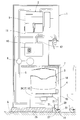
- FIG. 1 is a longitudinal front view showing an overall configuration of a water server according to a first embodiment of the present invention.
- FIG. 1 is an enlarged vertical side view of the vicinity of the container holder shown in FIG.
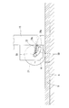
- a longitudinal front view showing a state in which a carpet is laid in front of the casing on the floor surface shown in FIG. 1 and a drawer is pulled out from the casing.
- Cross section of the water server shown in FIG. Cross section of the water server shown in FIG.
- Enlarged view of the caster shown in FIG. Enlarged cross-sectional view of the caster shown in FIG.
- the principal part front view which shows 2nd embodiment The principal part front view which shows 3rd embodiment
- FIG. 1 shows a water server according to a first embodiment of the present invention.
- the water server includes a housing 1, a temperature adjustment tank 2 disposed inside the housing 1, and a drawer 4 that is inserted into and removed from the lower portion of the housing 1 with a replaceable raw water container 3 placed thereon.
- the raw water container 3 placed on the drawer 4 and the raw water supply path 5 communicating between the temperature control tank 2 are provided.
- the housing 1 has an outer bottom surface 6 for standing on a horizontal surface.
- casing 1 stands on a floor surface.
- the casing 1 is long in the vertical direction perpendicular to the outer bottom surface 6 (hereinafter, this direction is simply referred to as “vertical direction”).
- the lower part of the housing 1 refers to the lower half of the housing 1.
- a drawer port 7 for storing the raw water container 3 and the drawer 4 is provided in the lower part of the housing 1.
- the temperature adjustment tank 2 can temporarily store the drinking water pumped up from the raw water container 3 by the raw water supply path 5 including the pump 8, and at least one of the functions of cooling or heating the stored drinking water. It has.
- the temperature adjustment tank 2 is divided into a cold water tank unit 9 having a function of cooling drinking water by heat exchange and a hot water tank unit 10 having a function of heating drinking water with a heater.
- the cold water tank section 9 is connected to a cold water discharge passage 11 for pouring out low-temperature drinking water collected in the lower part to the outside.
- a hot water pouring channel 12 Connected to the hot water tank section 10 is a hot water pouring channel 12 for pouring hot drinking water accumulated in the upper part to the outside.
- Each of the cold water pouring channel 11 and the hot water pouring channel 12 is provided with a cock that can be operated from the outside of the casing 1, and by opening the cock, the drinking water in the cold water tank unit 9 and the hot water tank unit 10 is put into a cup or the like.
- the drinking water pumped up in the raw water supply channel 5 is supplied to the upper part of the cold water tank unit 9, and when the drinking water is poured out from the hot water tank unit 10, the same amount of drinking water as the drinking water is stored in the cold water tank unit 9. It flows into the hot water tank unit 10 from above.
- the capacity of the cold water tank unit 9 is smaller than the capacity of the raw water container 3 and is generally about 2 to 4 liters.
- the capacity of the hot water tank unit 10 is generally about 1 to 2 liters.
- the raw water container 3 is placed on the drawer 4 with the water outlet 13 facing downward.
- natural water container 3 is formed flexibly so that it may shrink
- Such a raw water container 3 can be formed by blow molding of polyethylene terephthalate (PET) resin or polyethylene (PE) resin, for example.
- PET polyethylene terephthalate
- PE polyethylene
- the new raw water container 3 is filled with drinking water and has a capacity of about 8 to 20 liters.
- the raw water container 3 that has been used up to a predetermined pumping limit is a used one with almost no residual water inside.
- an intake passage communicating with the raw water container 3 and the atmosphere is provided.
- the drawer 4 is inserted into and removed from the drawer opening 7 of the housing 1 in a direction along a horizontal straight line.
- the direction of the horizontal straight line corresponds to the horizontal direction in the figure. In the following, this direction is simply referred to as the “out / in direction”, and in particular, the direction when the drawer 4 is pulled out from the drawer port 7 is called the “drawing direction”, and the direction when the drawer 4 is pushed back to the drawer port 7 is called the “return direction”. .
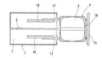
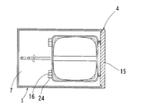
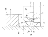
- the drawer 4 has a panel portion 15 that covers the drawer port 7 from the front side, a guided portion 17 that is guided in the loading / unloading direction and supported in the vertical direction by a guide portion 16 fixed in the drawer port 7 of the housing 1, A container holder portion 18 that connects the panel portion 15 and the guided portion 17, a caster 19 attached to the front side of the drawer 4, a bearing surface 21 that receives the axle 20 of the caster 19, and between the axle 20 and the panel portion 15. And a spring 22 hung over.
- the front side of the drawer 4 is a half of the drawer direction side of the drawer 4 which is a movable unit in the drawer direction with respect to the guide portion 16 fixed to the housing 1 (the right side in the drawing). The other half of the drawer 4 is the other half.
- the container holder portion 18 includes a joint 23 that is detachably connected to the water outlet 13 by placing the raw water container 3 from above, and a receiving portion 24 that is combined with the guided portion 17 so as to be relatively displaceable in and out. And have.
- the joint 23 is a starting end portion of the raw water supply path 5 and, as shown in FIG. 2, the opening of the water outlet 13 is formed by breaking through the cap of the water outlet 13, and the inner periphery of the opening and the self outer periphery are formed. It comes to adhere closely.
- the container holder portion 18 is configured to hold the raw water container 3 so that the close contact is maintained.
- the guide portion 16 is stationary with respect to the housing 1, contacts the drawer 4, guides it in the insertion / removal direction, and determines the support height of the drawer 4. Consists of.
- the guide portion 16 in the illustrated example is a groove-like rail portion that has a length in the loading / unloading direction and is arranged in a pair facing each other in the horizontal linear direction perpendicular to the loading / unloading direction.
- the guide portion 16 is fixed to a support plate portion erected on the bottom portion 25 of the housing 1.
- the guided portion 17 includes a contactable region that is guided and supported by the guide portion 16 in the drawer 4.
- the guided portion 17 in the illustrated example is a rod portion that fits in the rail inner surfaces of the guide portion 16 and the receiving portion 24 with a slight clearance, and is located at the innermost position of the drawer 4.
- the receiving portion 24 is a groove-like rail portion that has a length in the loading / unloading direction and is disposed so as to face the rail inner surface of the guide portion 16.
- the drawer 4 is pulled out from the storage position where the panel unit 15 and the housing 1 abut in the loading / unloading direction.
- the user grasps the panel unit 15 and performs the operation of taking in and out the drawer 4.
- the guided portion 17 is fitted to the guide portion 16 and the receiving portion 24 over the entire length.
- the guided portion 17 is shifted in the pulling direction with respect to the guide portion 16, and the receiving portion 24 is shifted in the pulling direction with respect to the guided portion 17. It has become.
- the guided portion 17 is prevented from being removed from the receiving portion 24 and the guide portion 16 unless special disassembly work is performed.
- 3 and 4 show a state in which the drawer 4 is pulled out in the pull-out direction, that is, the guided portion 17 is displaced most in the pull-out direction with respect to the guide portion 16, and the receiving portion 24 is most pulled out with respect to the guided portion 17. It depicts a state shifted in the direction.
- the sliding function in the insertion / removal direction between the receiving part 24 and the guided part 17 is employed so that the new raw water container 3 can be placed on the container holder part 18 from directly above.
- the guided portion 17 is always supported in the vertical direction by the lower guide surface 16a and the upper guide surface 16b along the loading / unloading direction, and the lower guide surface 16a and the upper guide surface 16b. Are guided from the both sides by the guide side surface 16c along the loading / unloading direction. Since the slide guide between the guided portion 17 and the receiving portion 24 and the vertical supportability are the same as those between the guide portion 16 and the guided portion 17, the guideability and supportability of the drawer 4 by the guide portion 16 is not impaired.
- the support height of the drawer 4 determined by the lower guide surface 16a of the guide portion 16 is such that the raw water supply path 5 taken out from under the container holder portion 18 contacts the floor surface A with the drawer 4 being pulled out. It is stipulated not to exist.
- the length of the drawer 4 in the illustrated example is determined by the panel portion 15 and the guided portion 17, but changes depending on the relative sliding between the guided portion 17 and the receiving portion 24.
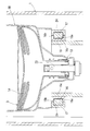
- a bearing frame 26 for mounting the leg wheel 19 is provided as shown in FIGS.
- the bearing surface 21 is formed on the inner periphery of the shaft hole of the bearing frame 26.
- the leg wheel 19 includes an axle 20 and a ring portion 27 having a rotation center on the axle 20.
- the axle 20 is loosely fitted in a shaft hole that penetrates the bearing frame 26 and is a member that can slide on the bearing surface 21. Stops for the shaft hole are provided on both sides of the axle 20.
- One retainer and the axle 20 are integrally formed parts.
- the other stopper is a mounting member for the axle 20.
- the leg wheel 19 is attached to the drawer 4 by passing the axle 20 through the shaft hole of the bearing frame 26 and attaching a mounting member.
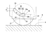
- the bearing surface 21 includes a front support 28 that supports the axle 20 on the front side, a back support 29 that supports the axle 20 on the back, and a front side. It comprises a path portion 30 that guides the axle 20 from the support portion 28 to the back side support portion 29.
- the front-side support portion 28 is in contact with the upper axis of the axle 20 so that the minimum height of the wheel portion 27 of the leg wheel 19 is the same height as the outer bottom surface 6 of the housing 1. The position is up to the position 28b that is closest to the front side.
- the back-side instruction unit 29 extends from a position 29a that comes into contact with the axle 20 from the upper side at the highest position of the bearing surface 21 to a position 29b that comes in contact with the axle 20 on the back-most side.
- the path portion 30 is a contactable region that allows the axle 20 to be displaced only between the front support portion 28 and the back support portion 29.
- the vicinity of the position 28 a in the illustrated example is a substantially horizontal portion in order to bear the load in the vertical direction on the bearing frame 26, and the vicinity of the position 28 b has an arc shape along the axle 20. From the position 29a to the position 29b in the illustrated example, an arc shape along the axle 20 is formed.
- the route portion 30 in the illustrated example gradually rises from the near side support portion 28 toward the far side in the loading / unloading direction.
- the leg wheel 19 is at the same height as the outer bottom surface 6 of the housing 1 at the lowest height of the wheel portion 27.
- the leg wheel 19 is higher than the outer bottom surface 6 of the housing 1 at the lowest height of the wheel portion 27.
- the other part of the drawer 4 such as the panel unit 15 is located higher than the outer bottom surface 6 regardless of whether the axle 20 is in the front support part 28 or the back support part 29.
- the difference in height between the axle height H1 at the rear support portion 29 shown in FIG. 8 and the axle height H2 at the front support portion 28 shown in FIG. 6 is 10 mm or more.
- the axle height H ⁇ b> 1 is a height from a horizontal plane that is in contact with the outer bottom surface 6 to an axis center of the axle 20 that is received by the back support portion 29.
- the axle height H ⁇ b> 2 is a height from a horizontal plane in contact with the outer bottom surface 6 to the axial center of the axle 20 received by the near side support portion 28. Therefore, the height difference H1-H2 corresponds to the vertical displacement range allowed for the axle 20 as shown in FIGS. 1 and 3, and corresponds to the vertical displacement range allowed for the leg wheel 19.
- the support height in the vertical direction of the drawer 4 as a whole is determined by the guide portion 16, the guided portion 17, and the receiving portion 24, regardless of whether the drawer 4 is in the storage position or the pulled-out position. For this reason, the weight on the drawer 4 side including the raw water container 3 does not normally need to be supported by the caster 19.
- the guide portion 16, the guided portion 17 and the receiving portion 24 overlap over substantially the entire length, and the front side of the drawer 4 is also supported by the guide portion 16.
- the drawer 4 is substantially not supported.
- the bottom 25 of the housing 1 is provided with a notch-shaped caster storage part 31 that opens to the front side from the outer bottom surface 6, so that the caster 19 can be stored at the same height as the outer bottom surface 6. It can be done.
- the spring 22 is formed of a coil spring having a front end hung on the panel portion 15 and a back end on the axle 20.
- the spring 22 is in a state in which an appropriate tension is applied when the axle 20 is received by the front support portion 28.
- the moderate tension is such that it does not rattle near the front support portion 28 due to vibration or the like, and even if the spring 22 is stretched due to aging, the tension is so small that tension is not lost.
- the spring 22 is pulled by the axle 20 to accumulate energy. This accumulation is a force that urges the axle 20 that is displaced beyond the path portion 30 to the front side.
- the spring 22 is illustrated only on one side of the axle 20, the same spring can be provided on the opposite side of the axle 20 in order to equally bias both sides of the axle 20. Further, the spring 22 is not limited to a tension spring, and a push spring from the opposite side that can obtain the same urging effect can also be adopted.
- the edge of the carpet B creates a step of about 10 mm in height with respect to the floor surface A.
- the wheel 27 of the leg wheel 19 moves in the pull-out direction (from left to right in the figure) while the axle 20 is received by the front support 28. Collide with the edge of carpet B.
- the axle 20 is displaced from the front support portion 28 beyond the path portion 30.
- the carpet 27 When the axle 20 is received by the back support portion 29, the carpet 27 can be rolled while being compressed to some extent by the wheel portion 27. Normally, the edge of the carpet B does not make a step exceeding 10 mm. However, if the height difference H1-H2 is set to 10 mm or more, it is possible to get on and off between the carpet B and the floor surface A slightly exceeding 10 mm in thickness. Sufficient utility can be obtained for provision to the home.
- the axle 20 When the raw water container 3 is placed on the container holder 18 from above with the wheel 27 on the carpet B, the axle 20 is positioned on the back support 29 or the path 30.
- the leg wheel 19 when the axle 20 is received by the back side support part 29, even if the raw water container 3 is placed roughly, the leg wheel 19 is quickly drawn to the floor surface A via the carpet B. The front side can be supported, and the housing 1 does not fall down.
- the axle 20 when the axle 20 is located in the path portion 30, it cannot be expected that the path portion 30 receives a vertical load. Therefore, when the raw water container 3 is roughly placed, the leg wheel 19 can support the front side of the drawer 4 according to the strength of the spring 22, and finally the axle 1 before the housing 1 falls down. 20 reaches the back support portion 29, and the caster 19 can support the front side of the drawer 4.
- the direction of travel of the drawer 4 on which the raw water container 3 is placed is guided and supported by the guide portion 16 and the guided portion 17. And is not determined by the user. Further, since the guide portion 16 is guided in the horizontal direction, the drawer 4 is prevented from moving freely when a heavy new raw water container 3 is placed on the drawer 4. Further, when the drawer 4 is pulled out, the wheel portion 27 of the leg wheel 19 collides in the pulling direction in a state where the axle 20 is received by the near side support portion 28, whereby the axle 20 is routed from the near side support portion 28.
- the axle 20 is received by the front side support part 28 or the back side support part 29 before the casing 1 falls down and before the front side of the drawer 4 hits the floor surface A, and the leg wheel 19 is displaced. Since the front side of the drawer 4 can be supported, the casing 1 can be prevented from being overturned so as not to damage the floor surface A without the adjustment work of the casters by the user. Therefore, it is possible to provide a water server with excellent workability. Moreover, since the compatibility with the carpet B having a thickness of 10 mm is imparted, it is possible to provide a water server suitable for popularization in general households.
- the near side support portion 28 according to the second embodiment is connected in an arc shape from a position 28 a to a position 28 b.
- the path portion 30 is continuous between a position 28a that is an end on the back side of the near side support portion 28 and a movement resistance region 30a that gradually descends toward the back side.
- the movement resistance region 30a has an arc shape with a different curvature and a center of curvature from the remaining portion 30b of the path portion 30 (which gradually rises as it advances toward the back side).
- the height difference H2 ⁇ H3 (when contacting at the position P) is set to 20% of the shaft diameter D of the axle 20.
- the axle height H3 is a height from the horizontal plane that is in contact with the outer bottom surface 6 to the axial center of the axle 20 that is in contact with the position P where the height of the movement resistance region 30a is the lowest.
- the height of the lower limit position P of the movement resistance region 30a can be avoided and the spring constant of the spring can be suppressed. Further, since the height difference H2-H3 is 30% or less of the shaft diameter D, when the wheel 27 collides with the carpet B, the behavior of the axle 20 sliding on the movement resistance region 30a is not reduced, and appropriate displacement is ensured. be able to.
- a single arcuate region including the movement resistance region 30 a may be a path portion 30 that continues to the vicinity of the back support portion 29.
- a movement resistance can be applied to the axle 20 while smoothly continuing from the position 28a of the front support 28 to the vicinity of the back support 29.
- the lower limit position P does not have a ridge line shape, and it is possible to prevent a collision sound when the axle 20 gets over the movement resistance region 30a.
- the movement resistance region 30 a can be provided by attaching the bearing frame 26 to the back side by inclining by an angle ⁇ as shown in the fourth embodiment.
- the bearing frame 26 has a mounting surface (a surface positioned on the extension of the back side lead line of the angle ⁇ in the figure) that is arranged along the wall surface of the panel portion 15 in order to determine a mounting angle (corresponding to the angle ⁇ ) with respect to the vertical direction. .
- a mounting surface a surface positioned on the extension of the back side lead line of the angle ⁇ in the figure
- an arc-shaped portion is formed in the clockwise direction from here.
- the 6 o'clock direction is a direction along the mounting surface.
- the normal direction at the position 28a is directed toward the front side by the attachment inclined at the angle ⁇ , and the normal direction at the lower limit position P included in the arc-shaped portion is directed in the vertical direction.
- the movement resistance region 30a is provided between the position 28a and the lower limit position P.
- the angle ⁇ is set to 5 ° or more regardless of the shaft diameter or the cross-sectional shape of the axle 20, a resistance for holding the axle 20 at the position 28a can be given.
Landscapes
- Engineering & Computer Science (AREA)
- Mechanical Engineering (AREA)
- Health & Medical Sciences (AREA)
- Public Health (AREA)
- Transportation (AREA)
- Handcart (AREA)
- Devices For Dispensing Beverages (AREA)
Description
2 温度調整タンク
3 原水容器
4 引出し
5 原水供給路
6 外底面
7 引出し口
16 ガイド部
17 被案内部
18 容器ホルダ部
19 脚車
20 車軸
21 軸受面
22 ばね
27 輪部
28 手前側支持部
29 奥側支持部
30 経路部
30a 移動抵抗領域
Claims (5)
- 筐体(1)の下部に交換式の原水容器(3)が収納され、この原水容器(3)内の飲料水が温度調整タンク(2)へ汲み上げられ、この温度調整タンク(2)内の飲料水が注水されるウォーターサーバーにおいて、
原水容器(3)が載置された状態で筐体(1)の下部に出し入れされる引出し(4)を備えており、
前記引出し(4)の奥側(17)は、前記筐体(1)に固定されたガイド部(16)によって水平一直線に沿った出し入れ方向に案内されると共に上下方向に支えられており、
前記引出し(4)の手前側に脚車(19)が取り付けられており、
前記脚車(19)の車軸(20)を受ける軸受面(21)は、当該車軸(20)を手前側で支持する手前側支持部(28)と、当該車軸(20)を奥側で支持する奥側支持部(29)と、前記手前側支持部(28)から前記奥側支持部(29)まで前記車軸(20)を導く経路部(30)とからなり、
前記車軸(20)が前記手前側支持部(28)に受けられているとき、前記脚車(19)が前記筐体(1)の外底面(6)と同高さになり、前記車軸(20)が前記奥側支持部(29)に受けられているとき、前記脚車(19)が前記筐体(1)の外底面(6)よりも高くなり、
前記引出し(4)が前記筐体(1)の下部から引き出されるとき、前記脚車(19)が引き出し方向に衝突することによって、前記車軸(20)が前記手前側支持部(28)から前記奥側支持部(29)まで変位させられることを特徴とするウォーターサーバー。 - 前記経路部以遠に変位させられた車軸(20)を手前側へ付勢するばね(22)を備えている請求項1に記載のウォーターサーバー。
- 前記手前側支持部(28)と前記経路部(30)は、奥側へ進むに連れて次第に下降する移動抵抗領域(30a)で連続している請求項2に記載のウォーターサーバー。
- 前記手前側支持部(28)での車軸高さ(H2)と、前記移動抵抗領域(30a)の下限位置(P)での車軸高さ(H3)との高低差は、前記車軸(20)の軸径(D)の30%以下になっている請求項3に記載のウォーターサーバー。
- 前記奥側支持部(29)での車軸高さ(H1)と、前記手前側支持部(28)での車軸高さ(H2)との高低差は、10mm以上になっている請求項1から4のいずれか1項に記載のウォーターサーバー。
Priority Applications (4)
| Application Number | Priority Date | Filing Date | Title |
|---|---|---|---|
| CN201380031229.5A CN104364186A (zh) | 2012-06-14 | 2013-04-23 | 饮水机 |
| KR1020157000943A KR20150018884A (ko) | 2012-06-14 | 2013-04-23 | 워터 서버 |
| US14/407,485 US9315140B2 (en) | 2012-06-14 | 2013-04-23 | Water dispenser |
| EP13804218.9A EP2862835A4 (en) | 2012-06-14 | 2013-04-23 | WATER DISPENSER |
Applications Claiming Priority (2)
| Application Number | Priority Date | Filing Date | Title |
|---|---|---|---|
| JP2012134887A JP5529209B2 (ja) | 2012-06-14 | 2012-06-14 | ウォーターサーバー |
| JP2012-134887 | 2012-06-14 |
Publications (1)
| Publication Number | Publication Date |
|---|---|
| WO2013187128A1 true WO2013187128A1 (ja) | 2013-12-19 |
Family
ID=49757963
Family Applications (1)
| Application Number | Title | Priority Date | Filing Date |
|---|---|---|---|
| PCT/JP2013/061906 Ceased WO2013187128A1 (ja) | 2012-06-14 | 2013-04-23 | ウォーターサーバー |
Country Status (7)
| Country | Link |
|---|---|
| US (1) | US9315140B2 (ja) |
| EP (1) | EP2862835A4 (ja) |
| JP (1) | JP5529209B2 (ja) |
| KR (1) | KR20150018884A (ja) |
| CN (1) | CN104364186A (ja) |
| TW (1) | TW201402446A (ja) |
| WO (1) | WO2013187128A1 (ja) |
Cited By (1)
| Publication number | Priority date | Publication date | Assignee | Title |
|---|---|---|---|---|
| JP2016028970A (ja) * | 2015-10-16 | 2016-03-03 | Next Innovation合同会社 | ウォータサーバの冷水又は温水の貯留装置及び熱伝達体 |
Families Citing this family (11)
| Publication number | Priority date | Publication date | Assignee | Title |
|---|---|---|---|---|
| US10123463B2 (en) | 2008-08-11 | 2018-11-06 | Green Revolution Cooling, Inc. | Liquid submerged, horizontal computer server rack and systems and method of cooling such a server rack |
| JP5583296B1 (ja) * | 2014-04-15 | 2014-09-03 | 株式会社コスモライフ | ウォーターサーバー |
| WO2017208817A1 (ja) * | 2016-05-30 | 2017-12-07 | パーパス株式会社 | ウォーターサーバー |
| TWI602749B (zh) * | 2017-04-25 | 2017-10-21 | Shi-Fen Zheng | Drinking bucket |
| CN108151326B (zh) * | 2017-12-22 | 2019-09-13 | 义乌市一宸新能源有限公司 | 一种改进的太阳能热水器 |
| DE202019100241U1 (de) * | 2019-01-16 | 2020-04-17 | Neoperl Gmbh | Trägerteil, Möbelstück-Baukasten, Möbelstück und korrespondierende Verwendung |
| US12389566B2 (en) | 2020-11-12 | 2025-08-12 | Green Revolution Cooling, Inc. | Multi-rack immersion cooling distribution system |
| US11805624B2 (en) | 2021-09-17 | 2023-10-31 | Green Revolution Cooling, Inc. | Coolant shroud |
| US20240074102A1 (en) * | 2022-08-31 | 2024-02-29 | Green Revolution Cooling, Inc. | Immersion Cooling Cabinet |
| WO2024059016A1 (en) | 2022-09-14 | 2024-03-21 | Green Revolution Cooling, Inc. | System and method for supplying uniform flow of dielectric cooling fluid for data servers |
| US12414273B2 (en) | 2023-01-25 | 2025-09-09 | Green Revolution Cooling, Inc. | Immersion cooling reservoir level control |
Citations (11)
| Publication number | Priority date | Publication date | Assignee | Title |
|---|---|---|---|---|
| JPS56161635U (ja) * | 1980-04-30 | 1981-12-01 | ||
| JP3055946U (ja) * | 1998-07-17 | 1999-02-02 | 有限会社 ヒズシステム | 飲料供給装置 |
| JP2001019094A (ja) * | 1999-07-05 | 2001-01-23 | Furukawa Altec Kk | 液体移送販売用容器 |
| JP2001153523A (ja) | 1999-11-19 | 2001-06-08 | Kyushu Kaihatsu Kikaku:Kk | 飲料用温水器及び飲料用冷水器及び飲料用温水・冷水器 |
| JP2007238144A (ja) * | 2006-03-09 | 2007-09-20 | Toshiba Electric Appliance Co Ltd | 給水装置および飲料機器 |
| JP2010143600A (ja) * | 2008-12-17 | 2010-07-01 | Kyushu Kaihatsu Kikaku:Kk | 給水機 |
| JP2010235135A (ja) * | 2009-03-30 | 2010-10-21 | Duskin Co Ltd | 冷温飲料水サーバー |
| JP4802299B1 (ja) | 2011-04-12 | 2011-10-26 | 株式会社オーケンウォーター | 給水ボトルの交換容易なウォーターサーバー |
| JP2012106765A (ja) * | 2010-11-17 | 2012-06-07 | Tech Corporation:Kk | ボトルウォーターを原水とする飲用水供給装置におけるボトルウォーターの飲用水供給装置への挿入方法および挿入装置 |
| JP2012171679A (ja) * | 2011-02-24 | 2012-09-10 | Tech Corporation:Kk | 飲用水供給装置へのボトルウォーター挿入装置および挿入方法 |
| JP2012171651A (ja) * | 2011-02-21 | 2012-09-10 | Tech Corporation:Kk | ボトルウォーターを原水とする飲用水供給装置におけるボトルウォーターの挿入方法および挿入装置 |
Family Cites Families (17)
| Publication number | Priority date | Publication date | Assignee | Title |
|---|---|---|---|---|
| US3949902A (en) * | 1973-06-11 | 1976-04-13 | Thompson Frank B | Portable dispensing bar |
| JPS56161635A (en) | 1980-05-17 | 1981-12-12 | Tdk Electronics Co Ltd | Method of manufacturing stator for variable porcelain capacitor |
| US4318575A (en) * | 1981-01-02 | 1982-03-09 | Eagle Sheet Metal Mfg. Company | Mobile file cabinet with drawer stabilizing wheel support means |
| US4861122A (en) * | 1987-06-08 | 1989-08-29 | Herman Miller, Inc. | Storage cabinet |
| DE3827919C1 (ja) * | 1988-08-17 | 1990-02-15 | Jungheinrich Unternehmensverwaltung Kg, 2000 Hamburg, De | |
| US5817075A (en) | 1989-08-14 | 1998-10-06 | Photogenesis, Inc. | Method for preparation and transplantation of planar implants and surgical instrument therefor |
| KR200142419Y1 (ko) * | 1996-08-08 | 1999-06-01 | 오희범 | 생수통 정립식 냉온수기 |
| DE29903353U1 (de) * | 1999-02-25 | 1999-08-26 | Apfel GmbH Metallverarbeitung, 69221 Dossenheim | Werkzeug- und/oder Materialschrank |
| WO2001038807A1 (en) * | 1999-11-19 | 2001-05-31 | Kabushiki Kaisha Kyusyu Kaihatsu Kikaku | Water heating device for beverage and others and water tank storage container used for the water heating device for beverage and others |
| SE520862C2 (sv) * | 2002-02-15 | 2003-09-09 | Enkatsu Solutions Ab | Hjulanordning |
| CN2723236Y (zh) * | 2004-07-28 | 2005-09-07 | 张寅� | 越野轮 |
| US20110163116A1 (en) * | 2006-07-14 | 2011-07-07 | Charles Dixon | Bottled water dispenser |
| US20080014064A1 (en) * | 2006-07-14 | 2008-01-17 | Charles Dixon | Bottled water dispenser |
| CN201065047Y (zh) * | 2007-07-14 | 2008-05-28 | 黄源 | 车身高度调整装置 |
| US20100116847A1 (en) * | 2008-11-07 | 2010-05-13 | Design By Pari, Llc | Under-counter water cooler appliance |
| US20100180606A1 (en) * | 2009-01-16 | 2010-07-22 | Moshe Gur | Partially Refrigerated Pet Supply Storage Device |
| CN102245496B (zh) * | 2009-07-23 | 2015-05-13 | 斯马特巴尔国际有限责任公司 | 自动饮料配制器 |
-
2012
- 2012-06-14 JP JP2012134887A patent/JP5529209B2/ja active Active
-
2013
- 2013-04-23 CN CN201380031229.5A patent/CN104364186A/zh active Pending
- 2013-04-23 WO PCT/JP2013/061906 patent/WO2013187128A1/ja not_active Ceased
- 2013-04-23 EP EP13804218.9A patent/EP2862835A4/en not_active Withdrawn
- 2013-04-23 KR KR1020157000943A patent/KR20150018884A/ko not_active Withdrawn
- 2013-04-23 US US14/407,485 patent/US9315140B2/en not_active Expired - Fee Related
- 2013-05-16 TW TW102117442A patent/TW201402446A/zh unknown
Patent Citations (11)
| Publication number | Priority date | Publication date | Assignee | Title |
|---|---|---|---|---|
| JPS56161635U (ja) * | 1980-04-30 | 1981-12-01 | ||
| JP3055946U (ja) * | 1998-07-17 | 1999-02-02 | 有限会社 ヒズシステム | 飲料供給装置 |
| JP2001019094A (ja) * | 1999-07-05 | 2001-01-23 | Furukawa Altec Kk | 液体移送販売用容器 |
| JP2001153523A (ja) | 1999-11-19 | 2001-06-08 | Kyushu Kaihatsu Kikaku:Kk | 飲料用温水器及び飲料用冷水器及び飲料用温水・冷水器 |
| JP2007238144A (ja) * | 2006-03-09 | 2007-09-20 | Toshiba Electric Appliance Co Ltd | 給水装置および飲料機器 |
| JP2010143600A (ja) * | 2008-12-17 | 2010-07-01 | Kyushu Kaihatsu Kikaku:Kk | 給水機 |
| JP2010235135A (ja) * | 2009-03-30 | 2010-10-21 | Duskin Co Ltd | 冷温飲料水サーバー |
| JP2012106765A (ja) * | 2010-11-17 | 2012-06-07 | Tech Corporation:Kk | ボトルウォーターを原水とする飲用水供給装置におけるボトルウォーターの飲用水供給装置への挿入方法および挿入装置 |
| JP2012171651A (ja) * | 2011-02-21 | 2012-09-10 | Tech Corporation:Kk | ボトルウォーターを原水とする飲用水供給装置におけるボトルウォーターの挿入方法および挿入装置 |
| JP2012171679A (ja) * | 2011-02-24 | 2012-09-10 | Tech Corporation:Kk | 飲用水供給装置へのボトルウォーター挿入装置および挿入方法 |
| JP4802299B1 (ja) | 2011-04-12 | 2011-10-26 | 株式会社オーケンウォーター | 給水ボトルの交換容易なウォーターサーバー |
Non-Patent Citations (1)
| Title |
|---|
| See also references of EP2862835A4 |
Cited By (1)
| Publication number | Priority date | Publication date | Assignee | Title |
|---|---|---|---|---|
| JP2016028970A (ja) * | 2015-10-16 | 2016-03-03 | Next Innovation合同会社 | ウォータサーバの冷水又は温水の貯留装置及び熱伝達体 |
Also Published As
| Publication number | Publication date |
|---|---|
| EP2862835A4 (en) | 2016-03-09 |
| JP5529209B2 (ja) | 2014-06-25 |
| KR20150018884A (ko) | 2015-02-24 |
| TW201402446A (zh) | 2014-01-16 |
| CN104364186A (zh) | 2015-02-18 |
| US20150165958A1 (en) | 2015-06-18 |
| EP2862835A1 (en) | 2015-04-22 |
| US9315140B2 (en) | 2016-04-19 |
| JP2013256329A (ja) | 2013-12-26 |
Similar Documents
| Publication | Publication Date | Title |
|---|---|---|
| JP5529209B2 (ja) | ウォーターサーバー | |
| US9993072B2 (en) | Sliding-pivoting mechanism of a shelf of a piece of furniture or of a domestic appliance, piece of furniture, and domestic appliance | |
| CN103201572B (zh) | 具有可拉出的冷却物容器的制冷器具 | |
| US20120104914A1 (en) | Dishwasher | |
| CN101999065B (zh) | 制冷器具 | |
| WO2018082314A1 (zh) | 阻尼器组件及导轨组件及洗碗机 | |
| CN102937359B (zh) | 冰箱的抽屉结构 | |
| CN105758104A (zh) | 具有可倾斜抽屉的冰箱 | |
| CN101990623B (zh) | 制冷器具 | |
| US20160235194A1 (en) | Retractable storage system | |
| CN111655077B (zh) | 用于引导柜子中抽屉的抽屉滑动件 | |
| US20080014064A1 (en) | Bottled water dispenser | |
| CN102171522B (zh) | 冷却设备 | |
| CN101223409A (zh) | 冷藏单元和/或冷冻单元 | |
| US20190166998A1 (en) | Guidance system | |
| CN107883638A (zh) | 冰箱 | |
| CN105101859A (zh) | 洗碗机篮的轨道组件 | |
| JP6067298B2 (ja) | 飲料サーバ | |
| US20070035219A1 (en) | Refrigerator | |
| CN206440059U (zh) | 冰箱 | |
| US11585595B2 (en) | Refrigerator | |
| JP7230182B2 (ja) | 乗上げ台 | |
| KR20090106958A (ko) | 시트 연동형 풋레스트 | |
| US20220274801A1 (en) | Device for storing at least one cable | |
| CN112890460B (zh) | 一种制冷设备 |
Legal Events
| Date | Code | Title | Description |
|---|---|---|---|
| 121 | Ep: the epo has been informed by wipo that ep was designated in this application |
Ref document number: 13804218 Country of ref document: EP Kind code of ref document: A1 |
|
| WWE | Wipo information: entry into national phase |
Ref document number: 14407485 Country of ref document: US |
|
| NENP | Non-entry into the national phase |
Ref country code: DE |
|
| REEP | Request for entry into the european phase |
Ref document number: 2013804218 Country of ref document: EP |
|
| WWE | Wipo information: entry into national phase |
Ref document number: 2013804218 Country of ref document: EP |
|
| ENP | Entry into the national phase |
Ref document number: 20157000943 Country of ref document: KR Kind code of ref document: A |