WO2013187129A1 - 情報処理装置、および情報処理方法、並びにプログラム - Google Patents
情報処理装置、および情報処理方法、並びにプログラム Download PDFInfo
- Publication number
- WO2013187129A1 WO2013187129A1 PCT/JP2013/061995 JP2013061995W WO2013187129A1 WO 2013187129 A1 WO2013187129 A1 WO 2013187129A1 JP 2013061995 W JP2013061995 W JP 2013061995W WO 2013187129 A1 WO2013187129 A1 WO 2013187129A1
- Authority
- WO
- WIPO (PCT)
- Prior art keywords
- image
- client
- unit
- virtual image
- information
- Prior art date
- Legal status (The legal status is an assumption and is not a legal conclusion. Google has not performed a legal analysis and makes no representation as to the accuracy of the status listed.)
- Ceased
Links
Images


Classifications
-
- H—ELECTRICITY
- H04—ELECTRIC COMMUNICATION TECHNIQUE
- H04N—PICTORIAL COMMUNICATION, e.g. TELEVISION
- H04N5/00—Details of television systems
- H04N5/222—Studio circuitry; Studio devices; Studio equipment
- H04N5/262—Studio circuits, e.g. for mixing, switching-over, change of character of image, other special effects ; Cameras specially adapted for the electronic generation of special effects
- H04N5/2621—Cameras specially adapted for the electronic generation of special effects during image pickup, e.g. digital cameras, camcorders, video cameras having integrated special effects capability
-
- G—PHYSICS
- G06—COMPUTING OR CALCULATING; COUNTING
- G06T—IMAGE DATA PROCESSING OR GENERATION, IN GENERAL
- G06T11/00—Two-dimensional [2D] image generation
- G06T11/60—Creating or editing images; Combining images with text
-
- G—PHYSICS
- G06—COMPUTING OR CALCULATING; COUNTING
- G06T—IMAGE DATA PROCESSING OR GENERATION, IN GENERAL
- G06T3/00—Geometric image transformations in the plane of the image
- G06T3/60—Rotation of whole images or parts thereof
-
- G—PHYSICS
- G09—EDUCATION; CRYPTOGRAPHY; DISPLAY; ADVERTISING; SEALS
- G09G—ARRANGEMENTS OR CIRCUITS FOR CONTROL OF INDICATING DEVICES USING STATIC MEANS TO PRESENT VARIABLE INFORMATION
- G09G5/00—Control arrangements or circuits for visual indicators common to cathode-ray tube indicators and other visual indicators
- G09G5/36—Control arrangements or circuits for visual indicators common to cathode-ray tube indicators and other visual indicators characterised by the display of a graphic pattern, e.g. using an all-points-addressable [APA] memory
- G09G5/37—Details of the operation on graphic patterns
- G09G5/377—Details of the operation on graphic patterns for mixing or overlaying two or more graphic patterns
-
- H—ELECTRICITY
- H04—ELECTRIC COMMUNICATION TECHNIQUE
- H04N—PICTORIAL COMMUNICATION, e.g. TELEVISION
- H04N21/00—Selective content distribution, e.g. interactive television or video on demand [VOD]
- H04N21/40—Client devices specifically adapted for the reception of or interaction with content, e.g. set-top-box [STB]; Operations thereof
- H04N21/41—Structure of client; Structure of client peripherals
- H04N21/414—Specialised client platforms, e.g. receiver in car or embedded in a mobile appliance
- H04N21/41407—Specialised client platforms, e.g. receiver in car or embedded in a mobile appliance embedded in a portable device, e.g. video client on a mobile phone, PDA, laptop
-
- H—ELECTRICITY
- H04—ELECTRIC COMMUNICATION TECHNIQUE
- H04N—PICTORIAL COMMUNICATION, e.g. TELEVISION
- H04N21/00—Selective content distribution, e.g. interactive television or video on demand [VOD]
- H04N21/40—Client devices specifically adapted for the reception of or interaction with content, e.g. set-top-box [STB]; Operations thereof
- H04N21/41—Structure of client; Structure of client peripherals
- H04N21/422—Input-only peripherals, i.e. input devices connected to specially adapted client devices, e.g. global positioning system [GPS]
- H04N21/42202—Input-only peripherals, i.e. input devices connected to specially adapted client devices, e.g. global positioning system [GPS] environmental sensors, e.g. for detecting temperature, luminosity, pressure, earthquakes
-
- H—ELECTRICITY
- H04—ELECTRIC COMMUNICATION TECHNIQUE
- H04N—PICTORIAL COMMUNICATION, e.g. TELEVISION
- H04N21/00—Selective content distribution, e.g. interactive television or video on demand [VOD]
- H04N21/40—Client devices specifically adapted for the reception of or interaction with content, e.g. set-top-box [STB]; Operations thereof
- H04N21/41—Structure of client; Structure of client peripherals
- H04N21/422—Input-only peripherals, i.e. input devices connected to specially adapted client devices, e.g. global positioning system [GPS]
- H04N21/4223—Cameras
-
- H—ELECTRICITY
- H04—ELECTRIC COMMUNICATION TECHNIQUE
- H04N—PICTORIAL COMMUNICATION, e.g. TELEVISION
- H04N21/00—Selective content distribution, e.g. interactive television or video on demand [VOD]
- H04N21/40—Client devices specifically adapted for the reception of or interaction with content, e.g. set-top-box [STB]; Operations thereof
- H04N21/43—Processing of content or additional data, e.g. demultiplexing additional data from a digital video stream; Elementary client operations, e.g. monitoring of home network or synchronising decoder's clock; Client middleware
- H04N21/4302—Content synchronisation processes, e.g. decoder synchronisation
- H04N21/4307—Synchronising the rendering of multiple content streams or additional data on devices, e.g. synchronisation of audio on a mobile phone with the video output on the TV screen
- H04N21/43072—Synchronising the rendering of multiple content streams or additional data on devices, e.g. synchronisation of audio on a mobile phone with the video output on the TV screen of multiple content streams on the same device
-
- H—ELECTRICITY
- H04—ELECTRIC COMMUNICATION TECHNIQUE
- H04N—PICTORIAL COMMUNICATION, e.g. TELEVISION
- H04N21/00—Selective content distribution, e.g. interactive television or video on demand [VOD]
- H04N21/60—Network structure or processes for video distribution between server and client or between remote clients; Control signalling between clients, server and network components; Transmission of management data between server and client, e.g. sending from server to client commands for recording incoming content stream; Communication details between server and client
- H04N21/65—Transmission of management data between client and server
- H04N21/658—Transmission by the client directed to the server
- H04N21/6587—Control parameters, e.g. trick play commands, viewpoint selection
-
- H—ELECTRICITY
- H04—ELECTRIC COMMUNICATION TECHNIQUE
- H04N—PICTORIAL COMMUNICATION, e.g. TELEVISION
- H04N23/00—Cameras or camera modules comprising electronic image sensors; Control thereof
- H04N23/60—Control of cameras or camera modules
- H04N23/63—Control of cameras or camera modules by using electronic viewfinders
- H04N23/633—Control of cameras or camera modules by using electronic viewfinders for displaying additional information relating to control or operation of the camera
-
- G—PHYSICS
- G09—EDUCATION; CRYPTOGRAPHY; DISPLAY; ADVERTISING; SEALS
- G09G—ARRANGEMENTS OR CIRCUITS FOR CONTROL OF INDICATING DEVICES USING STATIC MEANS TO PRESENT VARIABLE INFORMATION
- G09G2350/00—Solving problems of bandwidth in display systems
-
- G—PHYSICS
- G09—EDUCATION; CRYPTOGRAPHY; DISPLAY; ADVERTISING; SEALS
- G09G—ARRANGEMENTS OR CIRCUITS FOR CONTROL OF INDICATING DEVICES USING STATIC MEANS TO PRESENT VARIABLE INFORMATION
- G09G2370/00—Aspects of data communication
- G09G2370/02—Networking aspects
- G09G2370/022—Centralised management of display operation, e.g. in a server instead of locally
-
- G—PHYSICS
- G09—EDUCATION; CRYPTOGRAPHY; DISPLAY; ADVERTISING; SEALS
- G09G—ARRANGEMENTS OR CIRCUITS FOR CONTROL OF INDICATING DEVICES USING STATIC MEANS TO PRESENT VARIABLE INFORMATION
- G09G2370/00—Aspects of data communication
- G09G2370/04—Exchange of auxiliary data, i.e. other than image data, between monitor and graphics controller
-
- H—ELECTRICITY
- H04—ELECTRIC COMMUNICATION TECHNIQUE
- H04N—PICTORIAL COMMUNICATION, e.g. TELEVISION
- H04N23/00—Cameras or camera modules comprising electronic image sensors; Control thereof
- H04N23/60—Control of cameras or camera modules
- H04N23/63—Control of cameras or camera modules by using electronic viewfinders
Definitions
- the present disclosure relates to an information processing apparatus, an information processing method, and a program.
- the present invention relates to an information processing apparatus, an information processing method, and a program for executing augmented reality (AR) display.
- AR augmented reality
- an image obtained by superimposing a virtual image other than a captured image on a captured image of a camera is called an augmented reality (AR) image
- AR augmented reality
- mobile terminals such as smartphones equipped with a camera function and a display in addition to a communication function have become widespread, and applications using augmented reality (AR) images are often used in these smartphones.
- the object information is transmitted to the server, information associated with the object is received from the server, and the photographing object is displayed on the display unit of the smartphone. It is a process to display together.
- the image information transmitted from the server to the smartphone is various, for example, an image of a virtual character related to the shooting object, a person who has been shot in advance, or a landscape.
- Japanese Patent Application Laid-Open No. 2012-58838 discloses a conventional technique disclosed for generating and displaying an AR image.
- the virtual image transmitted from the server is, for example, a moving image obtained by shooting an actual person or the like
- this moving image is superimposed on the camera-captured image of the user's mobile terminal
- the captured image and the virtual image will move differently.
- a person as a virtual image is only stuck in the photographed image, and the person does not appear to exist in the photographed image. This is because the actual image captured by the user with the mobile terminal changes according to the change in the angle of the mobile terminal, while the virtual image provided by the server has no correlation with the change in the angle of the mobile terminal.
- the main reason is that
- An object of the present invention is to provide an information processing apparatus, an information processing method, and a program that change the virtual image according to the movement and realize the display of the AR image as if the virtual image exists in the captured image.
- the first aspect of the present disclosure is: An acquisition unit that acquires spatial position information of a terminal including a display unit that displays a video in which a virtual image is superimposed on a captured image captured by an imaging unit; A specifying unit for specifying display information for displaying the virtual image on the display unit according to the spatial position information of the terminal; In an information processing apparatus.
- the information processing device receives the virtual image from an imaging unit that captures an image, a display unit that displays a captured image of the imaging unit, and a server, A data processing unit that executes a process of superimposing and displaying the received virtual image on the captured image displayed on the display unit, wherein the data processing unit captures the image after a predetermined time according to movement information of the information processing apparatus; Estimated position information, transmitted estimated position information to the server, received from the server a virtual image taken from the estimated position, or the virtual image generation image and depth map, received image, or received image The process which displays the production
- the data processing unit is a round-trip delay time of communication with the server by applying the position / posture information and movement information of the imaging unit at the current time T.
- the imaging direction of the imaging unit after a time T + ⁇ t considering the network delay time ⁇ t is estimated, and the estimated direction is transmitted to the server as the estimated position information.
- the data processing unit is a round-trip delay time of communication with the server by applying the position / posture information and movement information of the imaging unit at the current time T.
- the probability of the imaging direction of the imaging unit after time T + ⁇ t considering the network delay time ⁇ t is calculated, an angle range with a high probability is selected, a virtual image from a plurality of viewpoints included in the selected angle range, or the A virtual image generation image and a depth map are received from the server.
- the data processing unit sets a relatively high-probability image as a high-resolution image and a relatively low-probability image in the selection angle range.
- Image data set as a resolution image is received from the server.
- the data processing unit when there is no significant difference in the probability in the selection angle range, displays virtual images from a plurality of viewpoints included in the selection angle range. Receive from the server as an image with the same resolution.
- the data processing unit is configured such that a viewpoint close to a shooting direction of the imaging unit at a display timing of the virtual image from a virtual image from a plurality of viewpoints received from the server.
- the virtual image is selected, or the virtual image generation image and the depth map are applied to generate a virtual image captured from a viewpoint close to the imaging direction of the imaging unit at the display timing of the virtual image, and to the display unit indicate.
- the second aspect of the present disclosure is: A communication unit that performs communication with the client; A data processing unit that selects and transmits a virtual image to be superimposed and displayed on a captured image of the client imaging unit displayed on the display unit of the client; The data processing unit A process of selecting a virtual image taken from the position of the client imaging unit after a predetermined time estimated according to the movement information of the client, or the virtual image generation image and a depth map as transmission data for the client, and transmitting to the client It exists in the information processing apparatus as a server to execute.
- the data processing unit applies the position / posture information and movement information of the client imaging unit at the current time T, so that the round-trip delay time of communication between server clients
- the shooting direction of the client imaging unit after a time T + ⁇ t considering the network delay time ⁇ t is estimated, and the virtual image shot from the estimated direction or the virtual image generation image and the depth map are selected as transmission data to the client.
- the data processing unit applies the position / posture information and movement information of the client imaging unit at the current time T, so that the round-trip delay time of communication between server clients
- the probability of the shooting direction of the client imaging unit after time T + ⁇ t considering the network delay time ⁇ t is calculated, an angle range with a high probability is selected, and virtual images from a plurality of viewpoints included in the selected angle range Is selected as transmission data for the client.
- the data processing unit sets a relatively high-probability image as a high-resolution image and a relatively low-probability image in the selection angle range.
- Transmission image data set as a resolution image is generated and transmitted to the client.
- the third aspect of the present disclosure is: An imaging unit for taking an image; A display unit for displaying a captured image of the imaging unit; A virtual image superimposed on the captured image displayed on the display unit, and a storage unit storing a virtual image corresponding to a plurality of viewpoints obtained by imaging an object from a plurality of different viewpoints; A data processing unit that executes the process of acquiring the virtual image from the storage unit and superimposing and displaying the acquired virtual image on the captured image displayed on the display unit; The data processing unit Estimating the imaging unit position after a predetermined time according to the motion information of the information processing device; A virtual image taken from an estimated position is selected from the storage unit and displayed, or the information processing apparatus executes processing for generating and displaying the virtual image based on the virtual image acquired from the storage unit.
- the storage unit stores a virtual image corresponding to a plurality of viewpoints and a depth map obtained by capturing an object from a plurality of different viewpoints
- the data processing unit stores the estimated position.
- the virtual image taken from the above is generated by applying the virtual image acquired from the storage unit and the depth map and displayed on the display unit.
- the data processing unit calculates a probability of the imaging direction of the imaging unit after a predetermined time according to motion information of the information processing device, and performs a high-probability virtual image Is selected from the storage unit or generated based on the virtual image acquired from the storage unit and displayed on the display unit.
- the fourth aspect of the present disclosure is: An information processing method executed in an information processing apparatus,
- the information processing apparatus includes: A communication unit that performs communication with the client; A data processing unit that selects and transmits a virtual image to be superimposed and displayed on a captured image of the client imaging unit displayed on the display unit of the client;
- the data processing unit A process of selecting a virtual image taken from the position of the client imaging unit after a predetermined time estimated according to the movement information of the client, or the virtual image generation image and a depth map as transmission data for the client, and transmitting to the client
- the fifth aspect of the present disclosure is: An information processing method executed in an information processing apparatus, An acquisition process in which a data processing unit acquires spatial position information of a terminal including a display unit that displays a video in which a virtual image is superimposed on a captured image captured by the imaging unit; In the information processing method, the data processing unit executes a specific process of specifying display information for displaying the virtual image on the display unit according to the spatial position information of the terminal.
- the sixth aspect of the present disclosure is: An information processing method executed in an information processing apparatus,
- the information processing apparatus includes: An imaging unit for taking an image; A display unit for displaying a captured image of the imaging unit; A virtual image superimposed on the captured image displayed on the display unit, and a storage unit storing a virtual image corresponding to a plurality of viewpoints obtained by imaging an object from a plurality of different viewpoints;
- a data processing unit that executes the process of acquiring the virtual image from the storage unit and superimposing and displaying the acquired virtual image on the captured image displayed on the display unit;
- the data processing unit Estimating the imaging unit position after a predetermined time according to the motion information of the information processing device; A virtual image captured from an estimated position is selected from the storage unit and displayed, or is generated based on a virtual image acquired from the storage unit and displayed on the display unit.
- the seventh aspect of the present disclosure is: A program for executing information processing in an information processing apparatus;
- the information processing apparatus includes: A communication unit that performs communication with the client; A data processing unit that selects and transmits a virtual image to be superimposed and displayed on a captured image of the client imaging unit displayed on the display unit of the client;
- the program is stored in the data processing unit.
- an eighth aspect of the present disclosure is A program for executing information processing in an information processing apparatus;
- An acquisition process of acquiring spatial position information of a terminal including a display unit that displays a video in which a virtual image is superimposed on a captured image captured by an imaging unit in a data processing unit;
- the data processing unit causes the display unit to execute a specific process for specifying display information for displaying the virtual image on the display unit according to the spatial position information of the terminal.
- the ninth aspect of the present disclosure is A program for executing information processing in an information processing apparatus;
- the information processing apparatus includes: An imaging unit for taking an image; A display unit for displaying a captured image of the imaging unit; A virtual image superimposed on the captured image displayed on the display unit, and a storage unit storing a virtual image corresponding to a plurality of viewpoints obtained by imaging an object from a plurality of different viewpoints; A data processing unit that executes the process of acquiring the virtual image from the storage unit and superimposing and displaying the acquired virtual image on the captured image displayed on the display unit;
- the program is stored in the data processing unit.
- the position of the imaging unit after a predetermined time is estimated according to the motion information of the information processing device, and a virtual image captured from the estimated position is selected from the storage unit for display or based on the virtual image acquired from the storage unit And a program for executing a process of generating and displaying on the display unit.
- the program of the present disclosure is a program that can be provided by, for example, a storage medium or a communication medium provided in a computer-readable format to an information processing apparatus or a computer system that can execute various program codes.
- a program in a computer-readable format, processing corresponding to the program is realized on the information processing apparatus or the computer system.
- system is a logical set configuration of a plurality of devices, and is not limited to one in which the devices of each configuration are in the same casing.
- the server includes a server that transmits a virtual image to a client, and a client that superimposes a camera-captured image and a virtual image transmitted from the server.
- the server transmits a virtual image captured from the client position after a predetermined time estimated according to the movement of the client (camera) to the client.
- the client after time T + ⁇ t considering the network delay time ⁇ t, which is the round trip delay time of communication between the server and client, by applying the position / attitude information and movement information of the client at the current time T in either the server or the client.
- the shooting direction is estimated, and a virtual image shot from the estimated direction is transmitted to the client.
- FIG. 3 is a diagram illustrating an example of an image provided from a server to a client in the first embodiment of the present disclosure.
- FIG. 6 is a diagram illustrating an example of an image provided from a server to a client in the second embodiment of the present disclosure. It is a figure which shows the flowchart explaining the process sequence of 2nd Example of this indication. It is a figure explaining the example of the transmission data with respect to a client. It is a figure explaining the example of the transmission data with respect to a client. It is a figure explaining the example of the transmission data with respect to a client. It is a figure explaining the example of the transmission data with respect to a client. It is a figure explaining the structural example of the server and client of 2nd Example of this indication. It is a figure explaining the structural example of the server and client of 3rd Example of this indication.
- FIG. 1 is a diagram illustrating a usage example of the processing of the present disclosure.
- the user A21 stands in front of the poster 10, and the user B22 takes an image including the poster 10 and the user A21 using a mobile terminal (client) 30 such as a smartphone having a camera function.
- client mobile terminal
- the captured image is, for example, a moving image.
- the mobile terminal (client) 30 transmits the shooting information to the server via the communication unit of the client (mobile terminal) 30.
- the server recognizes that the client (portable terminal) 30 is shooting an image including the poster 10 based on the shooting information received from the client (portable terminal) 30, and stores the content stored in the content database in the server, For example, moving image content obtained by photographing a person printed on the poster 10 is acquired and transmitted to the mobile terminal (client) 30.
- the portable terminal (client) 30 displays the content (moving image) received from the server so as to overlap the image being shot. It is the virtual image (real image) 31 in the display image of the client (mobile terminal) 30 in the figure. As shown in FIG. 1, the mobile terminal (client) 30 is an augmented reality (AR: Augmented Reality) that displays a captured image actually captured by the mobile terminal (client) 30 and a virtual image received from the server. ) Display the image.
- AR Augmented Reality
- the virtual image 31 displayed on the mobile terminal (client) 30 is an image of a person who does not actually exist in the place where the user A and the user B are present. However, the screen of the client (mobile terminal) 30 is displayed as if standing next to the user A21.
- the client (mobile terminal) 30 can shoot and record a captured image including the virtual image 31 as a moving image or a still image.
- the user B22 who is performing shooting processing using the mobile terminal (client) 30 performs image shooting while moving the mobile terminal (client) 30. At this time, the shooting direction changes, and the shot image changes according to the change in the shooting direction.
- the position of the camera 31 provided in the mobile terminal (client) 30 changes to various positions such as (a), (b), and (c) depending on the user.
- the shooting direction of the camera 31 has various settings such as (direction a), (direction b), and (direction c).
- the virtual image 31 is displayed in each shooting direction (direction a), (direction b), ( It is necessary to change the image according to the direction c).
- the virtual image 31 displayed on the mobile terminal (client) 30 is displayed on the mobile terminal (client) 30 by changing according to the movement of the mobile terminal (client) 30 as shown in FIG.
- the setting is as if the person as a virtual image is on the spot.
- FIG. 3 shows examples of ideal display images of virtual images corresponding to the following five shooting directions.
- FIG. 3A shows a shooting state from the front of the virtual image subject assumed position 32.
- FIG. 3 (R1) is a shooting state of the virtual image subject assumed position 32 from the right oblique direction.
- FIG. 3 (R2) is a shooting state of the virtual image subject assumed position 32 from the right direction.
- FIG. 3 (L1) is a shooting state from the left oblique direction of the virtual image subject assumed position 32.
- FIG. FIG. 3 (L2) is a shooting state from the left direction of the virtual image subject assumed position 32.
- the client that performs image capturing and display is not limited to the smartphone as shown in FIG. 1, and can be realized by various information processing devices such as a PC and glasses-type AR glasses.
- a virtual image such as a person is superimposed on an image being displayed on a client such as a smartphone or AR glass
- the virtual image is changed according to a change in the image to be superimposed.
- the virtual image can be displayed so as to exist in the base image to be superimposed.
- free viewpoint live-action moving image content observed from various viewpoints is transmitted from the server to the client, and is superimposed on, for example, a camera-captured image displayed on the display unit of the client.
- display of a virtual image having a natural movement according to the movement of the client (camera) is realized.
- Embodiment 1 Embodiment in which contents from different viewpoints that can be displayed on a client are transmitted from a server.
- Embodiment 2 Embodiment in which discrete multi-viewpoint content and depth information (depth map) corresponding to the content are transmitted from the server to the client, and an arbitrary viewpoint image to be displayed on the client is generated on the client side,
- the server distributes moving image content shot from a plurality of different viewpoints to the client.
- the client selects display content from the received moving image content of each viewpoint in accordance with the shooting angle information of the imaging unit (camera) of the client, and performs decoding and display processing of the selected moving image content. Since the client only needs to decode the video, the load is low. However, it is necessary to send a moving image of a larger number of viewpoints at a time, which increases the communication load.
- the server distributes moving image content from different viewpoints that are discontinuous, that is, discrete. Furthermore, it is the Example which provides the depth information (depth map) corresponding to the moving image content provided to a client together.
- the depth map is configured by data in which distance information from the camera to the subject is set in units of pixels.
- necessary display content that is, a virtual image observed from a desired direction is generated using moving image content from discontinuous different viewpoints. For example, the intermediate viewpoint images in the directions A to B are generated and displayed using the live-action images in the directions A and B and the depth map associated with each image.
- transmission data from the server to the client can be reduced. Images for at least two viewpoints (three or more viewpoints depending on the angle and position) may be transmitted. However, it is necessary to generate an intermediate viewpoint image on the client side, which increases the load on the client side.
- the client captures a camera-captured image that is a base image that is displayed or displayed on the client by a virtual image generated or selected according to the position / angle of the camera provided in the client.
- the virtual image provided by the server and superimposed on the client is, for example, when the virtual image is a live-action person image, the transparency of the pixel portion other than the person is maximized, and the transparency of the person area is set to 0.
- the moving image content has alpha channel information in pixel units called transparency information or mask information.
- network delay occurs in communication between the server and the client.
- the content provided from the server to the client needs to be a content that takes into account the network delay. That is, for example, based on the movement of the client, the shooting angle of the client after a predetermined time is predicted, and moving image content from a viewpoint within a predetermined range centered on the predicted angle is adaptively distributed. This process can significantly reduce the required bandwidth compared to distributing all-view video.
- real-time rendering of a virtual image according to the movement of the client described with reference to FIG. 3 is realized.
- the motion estimation of the client can be executed as a process using a marker included in the captured image of the client, for example. That is, camera position information, camera movement direction, movement speed, and the like are obtained from the marker shooting position, the client motion is predicted from these information, and the camera position and posture after a predetermined time are estimated. Moreover, it is good also as a structure using sensor information, such as an acceleration and a gyro sensor with which the client was equipped.
- sensor information such as an acceleration and a gyro sensor with which the client was equipped.
- FIGS. 1 to 3 in the processing of the present disclosure, an AR image in which a virtual image is superimposed on a captured image is generated and displayed on a display unit of a client.
- An example in which a virtual image is provided from a server to a client will be described.
- a configuration is also possible in which a virtual image is acquired from a storage unit in a client without receiving image provision from a server.
- the client 100 that is performing image shooting transmits shooting information to the server.
- the shooting information may be information that can confirm that the poster 10 shown in FIG. 1 is shot, for example, and may be a two-dimensional image such as a poster image or a cyber code (Cyber-Code) set in the poster 10.
- Identification information such as a barcode may be used.
- the server 200 Upon receiving the shooting information from the client, the server 200 acquires the moving image content provided to the client based on the shooting information from the database, and transmits the acquired moving image content. However, in this moving image transmission, the server selects and transmits a viewpoint image determined according to the movement of the client 100, that is, a virtual image observed from a direction estimated to be taken by the client after a predetermined time. . Details of this moving image content transmission will be described later.
- step S13 the client 100 superimposes and displays the moving image content received from the server 200 on the captured image.
- the basic processing flow of the server client is as described above.
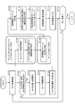
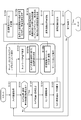
- the flow shown in FIG. 5 is a flow including a client process for executing an AR image display process in which a virtual image is superimposed on a captured image and a server process for providing a virtual image.
- the processing in steps S101 to S105 is processing executed by the client.
- the processes in steps S106 to S107 are processes executed by either the server or the client.
- the process of step S108 is a process executed by the server,
- the processes in steps S109 to S114 are processes executed by the client. It is.
- the processing shown in the flow is executed under the control of a data processing unit of the server or client, that is, a data processing unit having a CPU having a program execution function, for example, according to a program stored in the storage unit of the server or client.
- a data processing unit of the server or client that is, a data processing unit having a CPU having a program execution function, for example, according to a program stored in the storage unit of the server or client.
- Step S101 First, the client captures an image in step S101. For example, a poster as shown in FIG. 1 is photographed.
- step S ⁇ b> 102 the client determines whether or not information acquisition for calculating camera position / angle information necessary in the subsequent stage is successful.
- the information for calculating the position / angle information of the camera is, for example, a marker included in the captured image.
- the marker is, for example, a two-dimensional barcode such as a cyber code printed on the poster 10 shown in FIG. If such a marker is recognized, the position and angle of the camera can be calculated from the angle of the marker reflected in the camera image.
- the information for calculating the position / angle information of the camera is not limited to a marker such as a siper code, but may be an object such as a poster or a CD jacket.
- a marker such as a siper code
- an object such as a poster or a CD jacket.
- application information can be set in various ways.
- SLAM Simultaneous Localization And Mapping
- sensor information attached to the client device may be applied as information for calculating camera position / angle information.
- step S102 it is determined whether or not acquisition of the position / angle information of the camera executed by the client has succeeded. If the information cannot be obtained, it is determined that the subsequent AR image generation process is impossible, and the process ends. If information is obtained, the process proceeds to step S103.
- step S103 the client calculates the current position and orientation of the client (camera) by applying the information obtained in step S102.
- Step S104 Next, in step S104, the client acquires output values of the acceleration sensor and gyro sensor provided in the client.
- step S105 the client calculates the moving speed and moving direction of the client (camera). This process is executed by applying the current position and orientation of the client (camera) calculated in step S103 and the sensor information acquired in step S104, for example.
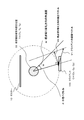
- step S105 shows a client 100 that performs image shooting and AR image display, and a virtual image subject assumed position 32.
- the client 100 can be freely moved by the user.
- step S104 the client velocity vector V1 is calculated.
- T (tx, ty, tz).
- a vector (C ⁇ T) is a radius vector r.
- the purpose of the processing in step S105 is to calculate the angular velocity ⁇ shown in FIG. 6, that is, the angular velocity ⁇ in the viewpoint switching direction with respect to the virtual image subject.
- An angular velocity ⁇ illustrated in FIG. 6 is an angular velocity according to the movement of the client 100 at the current time.
- the velocity vector v2 of the client in the direction perpendicular to the radius vector r is calculated.
- the velocity vector v2 is a velocity vector in the viewpoint switching direction corresponding to the virtual image subject.
- the angular velocity ⁇ in the viewpoint switching direction for the virtual image subject is Radius vector r;
- the velocity vector v2 of the client in the direction perpendicular to the radius vector r, Based on these, it can be calculated by the following formula. ⁇
- the angular velocity ⁇ in the viewpoint switching direction with respect to the virtual image subject is calculated according to the above formula.
- Step S106 The processing in steps S106 to S107 is processing executed in either the client or the server.
- step S106 for example, a ping command is transmitted / received between the client and the server, and a round trip time (RTT) is measured.
- RTT round trip time
- Step S107 Next, based on the moving direction / speed of the client (camera) obtained in step S105 and the network delay time obtained in step S106, the shooting angle of the client (camera) after a predetermined time is estimated and transmitted to the client.
- the angle range of the virtual image content to be set is set, and the transmission image is determined.
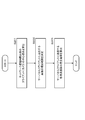
- step S107 Details of the processing in step S107 will be described with reference to FIG.
- the process of step S107 is executed by the processes of steps S201 to S203 in the flow shown in FIG.
- Step S201 First, the central viewpoint of the client (camera) after the network delay time ⁇ t is calculated.
- T is the current time
- the network delay time be ⁇ t
- the camera viewpoint of the client at the current time T is ⁇ T
- the angular velocity in the viewpoint switching direction of the client at the current time T is ⁇ T
- the network delay time ⁇ t is a round-trip delay time (latency) from the client to the server.
- the client operation by the user includes operations such as zoom-in / zoom-out in addition to moving the camera, but these can be handled by processing for changing the size of the subject.
- processing using the angular velocity ⁇ T in the viewpoint switching direction is performed.
- the data to be transmitted to the client by the server at the current time T is a virtual image observed from the estimated position of the client at the time T + ⁇ t after the network delay time ⁇ t from the current time T. That is, the server transmits a plurality of virtual image contents taken from viewpoints within a predetermined range around the client viewpoint ⁇ T + ⁇ t at time T + ⁇ t.
- the client selects and displays an image corresponding to the actual position of the client from these multiple images.
- the movement of the client is predicted, and the viewpoint image corresponding to the predicted position of the client is selected and provided from the server to the client.
- the amount of communication data is reduced, and the processing load on the client side is reduced, and efficient and highly accurate AR image display is realized.
- the client viewpoint ⁇ T + ⁇ t at time T + ⁇ t can be calculated according to the following equation if simply calculated.
- ⁇ T + ⁇ t ⁇ T + ⁇ T ⁇ t
- the client viewpoint ⁇ T + ⁇ t at time T + ⁇ t is calculated according to the above equation. That is, the central viewpoint of the client (camera) after the network delay time ⁇ t is calculated.
- the client viewpoint ⁇ T + ⁇ t at time T + ⁇ t may be calculated in consideration of the angular acceleration of the client and the angular velocity at time T + ⁇ t.
- Step S202 Next, the viewpoint range of the image transmitted from the server to the client is determined.
- the client viewpoint ⁇ T + ⁇ t obtained in the above step S201 is one viewpoint corresponding to the position of the client after ⁇ t from the current time T estimated under the assumption according to the data obtained at time T.
- the user does not always move the client according to the assumption according to the data obtained at time T.
- the moving speed and direction of the client (camera) may change sequentially.
- the network delay time is not constant and varies depending on the communication state of the network. Therefore, the client viewpoint ⁇ T + ⁇ t obtained in step S201 does not necessarily match the actual client viewpoint at time T + ⁇ t, but is only one viewpoint position predicted to occur with high probability.
- the server transmits only one virtual image content corresponding to the client viewpoint ⁇ T + ⁇ t to the client, if the actual client viewpoint matches the viewpoint ⁇ T + ⁇ t , the transmission image may be displayed. If the client viewpoint is shifted, an incorrect image is displayed.
- the server transmits a viewpoint image around the viewpoint in addition to the virtual image corresponding to the client viewpoint ⁇ T + ⁇ t estimated in step S201 to the client.
- viewpoint ranges corresponding to a plurality of different viewpoint image contents to be transmitted to the client are determined.
- Various modes can be used for determining the viewpoint range. For example, at the time of the current time T, the client's angular velocity ⁇ T + ⁇ t at time T + ⁇ t is predicted, and a log of the difference ratio between each predicted velocity and the actual client's time velocity T + ⁇ t's angular velocity ⁇ T + ⁇ t is collected. Processing such as setting ⁇ 2 ⁇ of the standard deviation to the angle range to be transmitted is possible.
- an angle range ⁇ n degrees may be set in advance, and a process of setting an image in the range of the client viewpoint ⁇ T + ⁇ t ⁇ n degrees estimated in step S201 as a transmission image may be performed. Furthermore, while setting an image in the range of the client viewpoint ⁇ T + ⁇ t ⁇ n degrees as a transmission image, Client angular velocity ⁇ T at time T, Network delay time ⁇ t, A function f ( ⁇ T , ⁇ t) with these values as parameters is set, and when the number of functions f ( ⁇ T , ⁇ t) exceeds a preset threshold, the angle range is increased stepwise. The angle range of the image may be determined.
- step S202 the following multi-view moving image content is determined as the content to be transmitted to the client.
- moving image content 1 obtained by photographing a subject (for example, a person) corresponding to a virtual image from the client viewpoint ⁇ T + ⁇ t calculated in step S201;
- moving image content 2 obtained by photographing a subject (for example, a person) corresponding to a virtual image from a viewpoint of + k degrees from the client viewpoint ⁇ T + ⁇ t ;
- moving image content 3 obtained by photographing a subject (for example, a person) corresponding to a virtual image from a viewpoint of ⁇ k degrees from the client viewpoint ⁇ T + ⁇ t ,
- moving image content 4 obtained by photographing a subject (for example, a person) corresponding to a virtual image from a viewpoint of + 2k degrees from the client viewpoint ⁇ T + ⁇ t ;
- moving image content 5 obtained by photographing a subject (for example, a person) corresponding to a virtual image from a
- Step S203 moving images from a plurality of viewpoints within an angle within a predetermined range including the client viewpoint ⁇ T + ⁇ t estimated in step S201 are determined as images to be transmitted to the client. For example, the moving image contents (1) to (5) above.
- the viewpoint positions of the plurality of moving image contents are viewpoint positions determined based on the motion prediction of the client (camera), and the client (camera) corresponds to the images (1) to (5) described above. It is estimated that the probabilities set for the viewpoint positions are different. That is, the client viewpoint ⁇ T + ⁇ t estimated in step S201 is the viewpoint that is estimated to occur with the highest probability as the client viewpoint at time T + ⁇ t, and it is estimated that the probability of occurrence decreases with distance from the viewpoint.
- a plurality of viewpoint image contents included in the viewpoint range set in step S202 are transmitted as the following settings. That is, the viewpoint image estimated to have a high probability as the client viewpoint at time T + ⁇ t is transmitted as a high-resolution image, and the image in the range estimated to have a low probability is transmitted as a low-resolution image. By executing image transmission with such settings, the amount of transmission data is reduced.
- step S203 in order to enable image transmission with such settings, the probability that a client (camera) is set at each viewpoint position included in the viewpoint range set in step S202 is estimated.
- a normal distribution having the maximum probability of the client viewpoint ⁇ T + ⁇ t at time T + ⁇ t calculated in step S201 is set, and a probability density function according to the normal distribution is applied to each client position (camera (camera)). ) Is estimated.
- FIG. 8 shows a normal distribution with the client viewpoint ⁇ T + ⁇ t at time T + ⁇ t calculated in step S201 as the maximum probability.
- the horizontal axis indicates the viewpoint, and the vertical axis indicates the occurrence probability.
- the center (0) of the viewpoint axis corresponds to the client viewpoint ⁇ T + ⁇ t at time T + ⁇ t calculated in step S201.
- the occurrence probability of the client viewpoint ⁇ T + ⁇ t at the time T + ⁇ t calculated in step S201 becomes higher than the occurrence probability of the surrounding viewpoints.
- the higher the angular velocity ⁇ of the client (camera) the smaller the difference between the occurrence probability of the client viewpoint ⁇ T + ⁇ t and the occurrence probability of surrounding viewpoints at the time T + ⁇ t calculated in step S201.
- the client is located at each viewpoint position included in the viewpoint range set in step S202. Estimate the probability that (camera) is set.
- the center (0) of the viewpoint axis is set to the client viewpoint ⁇ T + ⁇ t at the time T + ⁇ t calculated in step S201.
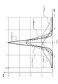
- the probability density function indicating the occurrence probability corresponding to each angle when the center (0) of the viewpoint axis is set to the actual client viewpoint ⁇ T at time T is set as shown in FIG.
- the probability density function shown in FIG. 9 is estimated to be located after time ⁇ t according to the angular velocity ⁇ of the client (camera), with the center (0) of the viewpoint axis set to the actual client viewpoint ⁇ T at time T. Indicates the probability of the client's location.
- the angular velocity ⁇ is ( ⁇ )
- the probability is higher in the left direction ( ⁇ direction)
- the angular velocity ⁇ is (+)
- the probability is higher in the right direction (+ direction).
- FIG. Network delay time: ⁇ t 100 ms
- the probability density function changes according to the value of the network delay time ⁇ t.
- the occurrence probability of the client viewpoint ⁇ T + ⁇ t at the time T + ⁇ t calculated in step S201 becomes higher than the occurrence probability of the surrounding viewpoints.
- the larger the network delay time ⁇ t the smaller the difference between the occurrence probability of the client viewpoint ⁇ T + ⁇ t and the occurrence probability of surrounding viewpoints at the time T + ⁇ t calculated in step S201.
- the network delay time ⁇ t may be generated by applying the value obtained at time T to generate the normal distribution data shown in FIG. Note that since the network delay time ⁇ t is measured by transmitting and receiving ping data once, an accurate delay time is not always measured. In consideration of this, the delay time fluctuation compensation may be executed.
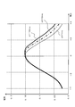
- FIG. 11 shows a delay time fluctuation compensation graph.
- the horizontal axis is the viewpoint axis with the client viewpoint ⁇ T + ⁇ t at the time T + ⁇ t calculated in step S201 as the center (0),
- the vertical axis indicates the occurrence probability.
- ⁇ t As a premise, it is assumed that the angular velocity ⁇ of the client (camera) at time T continues without change.
- the delay time standard deviation is ⁇ t , Assuming that the fluctuation compensation angle range is ⁇ t .
- ⁇ is a preset coefficient.
- An anomalous normal distribution function having a constant maximum value in the interval of the angle range 0 to ⁇ t (or ⁇ tn to 0) is defined as a probability density function.
- NORMDIST (x, u, ⁇ ) is after the probability density function of x in the century distribution with mean u and standard deviation ⁇ .
- the fluctuation compensation graph of the delay time shown in FIG. 11 is applied to the network delay time ⁇ t obtained based on transmission / reception of the ping command at time T, and fluctuation compensation is performed, and the result is reflected.
- the normal distribution data shown in FIG. 8 may be generated.
- step S203 of the flow shown in FIG. 7 a probability density function including normal distribution data shown in FIG. 8, for example, is set by applying each data measured at time T or its correction data by the above processing, and this probability According to the density function, the probability that a client (camera) is set at each viewpoint position included in the viewpoint range set in step S202 is estimated.
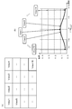
- step S107 of the flow shown in FIG. 5 the transmission image selection process based on the estimation of the camera angle is executed according to the flow shown in FIG. 7, and the probability that the client is set at each viewpoint of each selected image. Is calculated.
- the transmission image data is determined as shown in FIG. 12, and the probability of each determined transmission image, that is, the probability that the client is set to the position of the viewpoint image is calculated.
- the data shown in FIG. 12 is an example of data set in step S107.
- step S107 for example, as shown in FIG. 12, the following data (1) to (5) are determined as transmission images, and the probability of each image is calculated.
- Movie content 5 (View 5)
- transmission image determination and occurrence probability are determined.
- Step S108 Next, the process of step S108 of the flowchart shown in FIG. 5 will be described.
- the process of step S108 is executed on the server.
- the server generates a stream to be transmitted to the client using the data determined in the process of step S107, that is, for example, the trust image and probability data to be transmitted to the client shown in FIG.
- FIG. 13B is a graph of the probability density function described above with reference to FIG. 8, and is set for each angle with the estimated angle at time T + ⁇ t of the client (camera) as the center (0) of the horizontal axis. Indicates the probability of the client (camera). This probability corresponds to the probability in the data shown in FIG.
- the server has the highest probability as image 1 (View 1), image 2 (View 2), image 3 (View 3),... Image 7 (View 7) in descending order of probability.
- a plurality of stream data composed of a viewpoint image as a high resolution image (high bit rate image) and a low probability viewpoint image as a low resolution image (low bit rate image) are generated and transmitted to the client.
- the example shown in FIG. 13A is a setting example of a transmission image stream when the probability distribution shown in FIG. 13B is obtained.
- the image stream data as shown in FIG. 14A in which different viewpoint images are all data having the same resolution is used. It may be generated and transmitted.
- each viewpoint image may be transmitted as an individual stream, but may be set to transmit a plurality of images from a plurality of viewpoints in one stream.
- the image stream of each viewpoint is not generated in real time but is generated in advance for each resolution and bit rate and stored in a database.
- the image data transmitted from the server to the client is data encoded by a predetermined encoding algorithm such as MPEG, and needs to be decoded on the client side.
- a predetermined encoding algorithm such as MPEG
- the client When switching the display to a different viewpoint image stream, the client must select a different moving image stream and start a new decoding, and there is a possibility that smooth image switching cannot be performed due to the delay at the time of switching the stream. .
- the image stream provided to the client (A) a video sequence in which all frames are key frames; (B) a normal video sequence; These two types of image streams may be set.
- a moving image sequence in which all frames are key frames is, for example, encoded data composed of image frames that can independently decode each image frame.
- a normal moving image sequence is, for example, encoded data that needs to be decoded with reference to preceding and subsequent image frames.
- the client first reads the first frame from the “video sequence in which all frames are key frames”, performs high-speed decoding processing and displays it on the display unit, and the second and subsequent frames from the “normal video sequence”. Processing such as reading and decoding and continuing display can be performed, and delay in switching display can be reduced.
- the stream that delivers the image with the highest probability is set as a fixed stream
- a configuration may be used in which partial real-time encoding is performed in which content of different viewpoints changed according to the movement of the client is distributed using the same fixed stream.
- the client can display a high-quality image with a high probability.
- an image of a viewpoint with a low probability is also transmitted, it is possible to reduce the possibility that a corresponding viewpoint image cannot be displayed even if there is a sudden movement of the client.
- Step S109 Returning to the flow of FIG. 5, the description of the processing sequence of the first embodiment will be continued.
- the client When image transmission is executed in the server in step S108, the client next receives an image stream of the virtual image in step S109.
- the stream is composed of moving image data of a plurality of viewpoint images described with reference to FIGS. 13 (A) and 14 (A).
- Step S110 the client calculates the position / angle of the camera at the time of receiving the stream, selects a virtual image to be displayed on the display unit of the client, and further determines a superposition position of the selected virtual image.
- This camera position / angle calculation process is the same as the process of steps S102 to S103 described above, and the calculation result is applied to determine the virtual image selection process and the superimposed position.
- Step S111 Next, in step S111, the client executes a decoding process of the virtual image stream selected as the image to be displayed.
- Step S112 Next, in step S112, the client superimposes the decoded content on the camera photographed image being displayed on the display unit of the client.
- step S113 the client outputs an AR image in which the virtual image is superimposed on the captured image as the final result on the display unit (display) of the client.
- step S114 it is determined whether or not an end condition set in advance, for example, an end condition such as the end of the image capturing process or the end of the application has occurred. If the end condition has occurred, no processing is ended. If the end condition does not occur, the process returns to step S101 and the same processing is repeated.
- the virtual image transmitted from the server is displayed superimposed on the captured image being displayed on the display unit of the client.
- the processing of steps S105 to S107 is omitted, the acquisition of the camera position and orientation information in step S103, the movement direction and speed of the camera in step S104, and the acquisition information, that is, A configuration may be adopted in which a virtual image to be displayed on the display unit is generated or selected and output to the display unit based on spatial position information such as the position, posture, or movement of the camera.
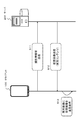
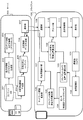
- FIG. 15 shows a configuration example of the server 200 and the client 100 that execute the first embodiment. Data is transmitted and received between the communication unit 108 of the client 100 and the communication unit 207 of the server 200.
- the network delay estimation unit 106 and the angle range estimation unit 107 shown in the configuration of the client 100 may be set as components of the server 200 instead of the client 100.
- the client 100 and the server 200 illustrated in FIG. 15 execute processing according to the flow illustrated in FIG. 5 described above.
- the processing executed by each configuration shown in FIG. 15 will be described in association with the processing of each step in the flow of FIG.
- the imaging unit (camera) 101 of the client 100 executes the camera image acquisition process in step S101 of the flow shown in FIG.
- the image recognition unit 102 executes the camera position / posture calculation information acquisition process in step S102 of the flow of FIG. Specifically, for example, a marker recognition process set on a subject such as a poster shown in FIG. 1 is executed.
- the client (camera) position / orientation calculation unit 103 executes the camera position / orientation calculation process in step S103 of the flow of FIG.
- the sensor (acceleration measurement sensor or the like) 104 executes sensor information acquisition processing in step S104 in the flow of FIG.
- the client moving speed direction calculation unit 105 executes a client (camera) moving speed direction calculation process in step S105 of the flow of FIG.
- the network delay estimation unit 106 executes network delay estimation processing in step S106 of the flow of FIG.
- the angle range estimation unit 107 executes the processing of step S107 in the flow of FIG. 5, that is, processing such as transmission image determination processing and probability estimation based on client (camera) position estimation.
- the network delay estimation unit 106 and the angle range estimation unit 107 may be set on the server 200 side and executed as processing of the server 200.
- the angle range estimation unit 107 determines a transmission image based on the position estimation of the client (camera), and calculates a probability corresponding to each transmission image, that is, a probability that the client is set at a viewpoint position corresponding to each image. Specifically, for example, the data described above with reference to FIG. 12 is generated. This data is input to the transmission image data generation unit 206 of the server 200 via the communication unit.
- the server 200 generates image content (moving image stream) of a plurality of viewpoints to be provided to the client in advance and holds it as each viewpoint corresponding content 205.
- the server executes the following process as a pre-process to generate each viewpoint corresponding content 205.
- the depth information (depth map) generation unit 202 acquires content stored in the content database 201, that is, image content from a plurality of discrete viewpoints, and generates depth information (depth map) 203 corresponding to the image. To do. Further, the intermediate viewpoint image generation unit 204 applies the content stored in the content database 201 and the depth information (depth map) 203, and image content from an intermediate viewpoint that is not included in the content stored in the content database 201. Is generated.
- the server 200 includes content stored in the content database 201 and image content from an intermediate viewpoint that is not included in the content stored in the content database 201. For example, each viewpoint image of 360 degrees with respect to a certain subject corresponds to each viewpoint.
- the content 205 is generated in advance.
- the transmission image data generation unit 206 of the server 200 performs processing for generating a transmission stream based on the image content transmitted from each viewpoint corresponding content 205 to the client. That is, the process of step S108 in the flow shown in FIG. 5 is executed.
- the server generates a stream to be transmitted to the client using the image and probability data to be transmitted to the client illustrated in FIG. Specifically, for example, combination data of image contents of a plurality of viewpoints as shown in FIGS. 13 (A) and 14 (A).
- Transmission data generated by the transmission image data generation unit 206 is transmitted to the communication unit 108 of the client 100 via the communication unit 207.
- the communication unit 108 of the client 100 executes the virtual image stream reception process in step S109 of the flow of FIG.
- the content selection & superimposition position calculation unit 109 of the client 100 executes the process of step S110 in the flow of FIG. 5, that is, the selection of the virtual image and the determination process of the superposition position. That is, the camera position / angle at the time of receiving the stream is calculated, a virtual image to be displayed on the display unit of the client is selected, and a superimposed position of the selected virtual image is determined.
- the decoding unit 110 executes the process of step S111 in the flow of FIG. 5, that is, the decoding process of the selected virtual image stream.
- the display control unit 111 outputs the AR image obtained by superimposing the decoded content on the camera-captured image displayed on the display unit 112 of the client 100 in steps S112 and S113 in the flow of FIG.
- the configuration illustrated in FIG. 15 is a diagram illustrating the main configuration of the server and the client.
- the server and the client include, for example, a CPU that controls the processing described with reference to FIG. 6 in addition to the configuration illustrated in FIG. And a storage unit storing a program to be executed by the control unit.
- discrete multi-viewpoint content and depth information (depth map) corresponding to the content are transmitted from the server to the client, and an arbitrary viewpoint image to be displayed on the client is generated on the client side.
- the server transmits a virtual image generation image and a depth map for generating a virtual image to be displayed to the client to the client.
- moving image content from a viewpoint in a certain angle range for example, n moving image contents from moving image 1 to moving image n shown in FIG. 16 are transmitted to the client. From the content, processing that selects and displays content suitable for the client's angle or the like has been performed.
- an image of several discrete viewpoints for example, a moving picture with only three viewpoints as shown in FIG.
- depth information (depth map) corresponding to these three transmission moving images is also transmitted to the client.
- the client applies the images from these discrete viewpoints and the depth map, generates an intermediate viewpoint image from the viewpoint between the moving image 1 and the moving image 2, for example, and generates and displays an image to be displayed on the client.
- the configuration of the second embodiment has an advantage that the amount of image data transmitted from the server to the client can be reduced.
- the processing sequence of the second embodiment will be described with reference to the flowchart shown in FIG.
- the flow shown in FIG. 18 includes processing common to the flow of FIG. 5 described above as the processing sequence of the first embodiment.
- the same processes as in the first embodiment are the processes in steps S101 to S106, the process in step S109, and the processes in steps S112 to S114.
- Step S107b Step S108b, Step S110b, Step S111b, These processes are different from those in the first embodiment.
- the flow shown in FIG. 18 includes a client process for executing an AR image display process in which a virtual image is superimposed on a captured image, and a server process for providing a virtual image.
- the processing in steps S101 to S105 is processing executed by the client.
- the processes in steps S106 to S107 are processes executed by either the server or the client.
- the process of step S108 is a process executed by the server,
- the processes in steps S109 to S114 are processes executed by the client. It is.
- the processing shown in the flow is executed under the control of a data processing unit of the server or client, that is, a data processing unit having a CPU having a program execution function, for example, according to a program stored in the storage unit of the server or client.
- a data processing unit of the server or client that is, a data processing unit having a CPU having a program execution function, for example, according to a program stored in the storage unit of the server or client.
- Step S101 First, the client captures an image in step S101. For example, a poster as shown in FIG. 1 is photographed.
- Step S102 Next, in step S ⁇ b> 102, the client determines whether or not information acquisition for calculating camera position / angle information necessary in the subsequent stage is successful.
- the information for calculating the position / angle information of the camera is, for example, a marker included in the captured image.
- the marker is, for example, a two-dimensional barcode such as a cyber code printed on the poster 10 shown in FIG.
- step S103 the client calculates the current position and orientation of the client (camera) by applying the information obtained in step S102.
- Step S104 Next, in step S104, the client acquires output values of the acceleration sensor and gyro sensor provided in the client.
- step S105 the client calculates the moving speed and moving direction of the client (camera). This process is executed by applying the current position and orientation of the client (camera) calculated in step S103 and the sensor information acquired in step S104, for example.
- a specific processing example of step S105 is as described above with reference to FIG.
- Step S106 The processing in steps S106 to S107b is processing executed in either the client or the server.
- step S106 for example, a ping command is transmitted / received between the client and the server, and a round trip time (RTT) is measured.
- RTT round trip time
- Step S107b Next, based on the moving direction / speed of the client (camera) obtained in step S105 and the network delay time obtained in step S106, the shooting angle of the client (camera) after a predetermined time is estimated and transmitted to the client.
- the angle range of the virtual image content to be set is set, and the transmission image is determined.
- step S107b first, the processes of steps S201 to S203 in the flow shown in FIG. 7 are executed as in the first embodiment described above.
- the viewpoint image in the angle range to be transmitted shown in FIG. 12 and the probability thereof, that is, the probability that the client is set to the position of the viewpoint image is calculated.
- not all of these images but only images of discrete viewpoints are set as images to be transmitted to the client.
- the closest viewpoint image combination is selected as the transmission image.
- Step S108b The server generates an image data stream that combines the transmission image data determined in step S107b and the depth map.
- a stream generation example will be described with reference to FIG.
- FIG. 19A shows the probability distribution data corresponding to the viewpoint calculated according to the flow shown in FIG. Using this data, a discrete viewpoint image to be transmitted to the client is selected and transmitted to the client.
- FIG. 19B shows an example of transmission image data.
- the viewpoint image (View 1) at the time T + ⁇ t the viewpoint images (View 2) and (View 3) at positions separated by a predetermined angle are transmitted as high-resolution images.
- Each image is transmitted together with depth information (depth map) corresponding to each image to the client.
- depth map depth information
- the client selects an intermediate viewpoint image between (View 1) and (View 2) as a display image
- the client uses the (View 1) and (View 2) images and the intermediate viewpoint using the depth map of each image. Generate and display an image. Similar processing is performed when intermediate viewpoint images of other images are necessary.
- FIG. 20 is a processing example in which transmission images are further reduced.
- FIG. 20A shows the probability distribution data corresponding to the viewpoint calculated according to the flow shown in FIG. 7, as in FIG. 19A. Using this data, a discrete viewpoint image to be transmitted to the client is selected and transmitted to the client.
- FIG. 20B shows an example of transmission image data.
- the viewpoint images (View1) that are the viewpoint images at time T + ⁇ t and the viewpoint images (View2) and (View3) that are separated by a predetermined angle are transmitted as high-resolution images. Further, only (View6) and (View7) at both ends of the images (View4) to (View7) corresponding to the angle of the viewpoint distant from (View1) which is the viewpoint image at time T + ⁇ t are transmitted as low-resolution images, and (View4 ) And (View 5) are not transmitted.
- the client selects an intermediate viewpoint image between (View2) and (View6) as a display image
- the client uses the (View2) and (View6) images and an intermediate viewpoint using the depth map of each image. Generate and display an image. Similar processing is performed when intermediate viewpoint images of other images are necessary.
- the probability of the position of (View1) that is the viewpoint image at time T + ⁇ t is extremely high, and the probability at a distant angle around the probability distribution is low. It is good also as a setting which does not transmit the image of this. That is, as shown in FIG. 21B, only the viewpoint images (View 2) and (View 3) that are at a predetermined angle apart from the viewpoint image at time T + ⁇ t are transmitted as high-resolution images.
- step S108b of the flow of FIG. 18 a transmission image stream is generated and transmitted to the client with various settings as described above.
- a discrete viewpoint image is selected, transmitted to the client together with the depth map, and processing for generating and displaying the image as needed on the client side is performed.
- Step S109 Returning to the flow of FIG. 18, the description of the processing sequence of the second embodiment will be continued.
- the client When image transmission is executed in the server in step S108b, the client next receives an image stream of the virtual image in step S109.
- the stream is composed of moving image data of multiple viewpoint images and a depth map described with reference to FIGS.
- Step S110b the client calculates the position and angle of the camera at the time of receiving the stream, determines the viewpoint position of the virtual image displayed on the display unit of the client, and further determines the superimposed position of the determined virtual image corresponding to the viewpoint. decide.
- This camera position / angle calculation process is the same as the process of steps S102 to S103 described above, and the viewpoint position and superimposition position of the virtual image are determined by applying this calculation result.
- step S111b the client executes image stream decoding processing necessary for generating an image corresponding to the determined viewpoint position. For example, when the image shown in FIG. 20B is received and the intermediate viewpoint images of (View 3) and (View 7) are determined as display images, the images of (View 3) and (View 7) are decoded, The intermediate viewpoint image is generated by applying the depth map of the image.
- Step S112 Next, in step S112, the client superimposes the generated image content on the camera photographed image being displayed on the display unit of the client.
- step S113 the client outputs an AR image in which the virtual image is superimposed on the captured image as the final result on the display unit (display) of the client.
- Step S114 it is determined whether or not an end condition set in advance, for example, an end condition such as the end of the image capturing process or the end of the application has occurred. If the end condition has occurred, no processing is ended. If the end condition does not occur, the process returns to step S101 and the same processing is repeated.
- an end condition set in advance for example, an end condition such as the end of the image capturing process or the end of the application has occurred. If the end condition has occurred, no processing is ended. If the end condition does not occur, the process returns to step S101 and the same processing is repeated.
- the virtual image transmitted from the server is displayed superimposed on the captured image being displayed on the display unit of the client.
- FIG. 22 shows a configuration example of the server 200 and the client 100 that execute the second embodiment. Data is transmitted and received between the communication unit 108 of the client 100 and the communication unit 207 of the server 200.
- the network delay estimation unit 106 and the angle range estimation unit 107 shown in the configuration of the client 100 may be set as components of the server 200 instead of the client 100.
- the client 100 and the server 200 illustrated in FIG. 22 execute processing according to the flow illustrated in FIG. 19 described above.
- the processing executed by each configuration shown in FIG. 22 will be described in association with the processing of each step in the flow of FIG.
- the imaging unit (camera) 101 of the client 100 executes the camera image acquisition process in step S101 of the flow shown in FIG.
- the image recognition unit 102 executes the camera position / posture calculation information acquisition process in step S102 of the flow of FIG. Specifically, for example, a marker recognition process set on a subject such as a poster shown in FIG. 1 is executed.
- the client (camera) position / orientation calculation unit 103 executes the camera position / orientation calculation process in step S103 of the flow of FIG.
- the sensor (acceleration measurement sensor or the like) 104 executes sensor information acquisition processing in step S104 of the flow of FIG.
- the client moving speed direction calculating unit 105 executes the client (camera) moving speed direction calculating process in step S105 of the flow of FIG.
- the network delay estimation unit 106 executes network delay estimation processing in step S106 of the flow of FIG.
- the angle range estimation unit 107 executes the processing of step S107b in the flow of FIG. 19, that is, processing such as transmission image determination processing and probability estimation based on the position estimation of the client (camera).
- the network delay estimation unit 106 and the angle range estimation unit 107 may be set on the server 200 side and executed as processing of the server 200.
- the angle range estimation unit 107 determines a transmission image based on the position estimation of the client (camera), and calculates a probability corresponding to each transmission image, that is, a probability that the client is set at a viewpoint position corresponding to each image. Specifically, for example, the data described above with reference to FIG. 12 is generated. This data is input to the transmission image data generation unit 206 of the server 200 via the communication unit.
- the server 200 holds in the content database 201 image content (moving image streams) of a plurality of discrete viewpoints to be provided to the client in advance.
- the server acquires content stored in the content database 201, that is, image content from a plurality of discrete viewpoints, and depth information (depth map) corresponding to this image as preprocessing. ) 203 is generated.
- the transmission image data generation unit 206 of the server 200 performs processing for generating a transmission stream based on the image content transmitted from each viewpoint corresponding content 205 to the client. That is, the process of step S108b of the flow shown in FIG. 19 is executed.
- the server sets data combining a plurality of discrete viewpoint images and depth maps as data to be provided to a large number of clients.
- Transmission data generated by the transmission image data generation unit 206 is transmitted to the communication unit 108 of the client 100 via the communication unit 207.
- the communication unit 108 of the client 100 executes the virtual image stream reception process in step S109 of the flow of FIG.
- the content selection & superimposition position calculation unit 109 of the client 100 executes the process of step S110b in the flow of FIG. 19, that is, the process of determining the viewpoint position of the virtual image to be displayed and the superimposition position. That is, the position and angle of the camera at the time of receiving the stream are calculated, the viewpoint position of the virtual image displayed on the display unit of the client is determined, and the superimposed position of the determined virtual image is determined.
- the decoding unit 110 executes the process of step S111 in the flow of FIG. 19, that is, the decoding process of the image stream necessary for generating the image corresponding to the determined viewpoint position. For example, when the image shown in FIG. 20B is received and the intermediate viewpoint images of (View 3) and (View 7) are determined as display images, the images of (View 3) and (View 7) are decoded, The intermediate viewpoint image is generated by applying the depth map of the image.
- the display control unit 111 outputs the AR image in which the processing of steps S112 and S113 in the flow of FIG. 19, that is, the decoded content is superimposed on the camera captured image being displayed on the display unit 112 of the client 100.
- the virtual image transmitted from the server is displayed superimposed on the captured image being displayed on the display unit of the client.
- the process of the second embodiment has the following advantages.
- (Advantage 1) Network bandwidth can be reduced.
- the image quality can be improved while maintaining the bandwidth. This is because the number of viewpoints to be transmitted is minimum and an image with two viewpoints is sufficient.
- (Advantage 2) The client terminal is further robust against the steep movement of the client terminal. In the stream to be transmitted, it is possible to skip the original video in the middle of the viewpoint with low probability and send only the video at both ends, and transmit the viewpoint section with low probability by increasing the parallax between viewpoints to be interpolated. It is possible to reduce the number of streams. This makes it easier to widen the range of angles that can be transmitted compared to the first embodiment.
- the third embodiment is an embodiment that combines the first and second embodiments described above.
- moving image content from a viewpoint in a certain angle range for example, n moving image contents from moving image 1 to moving image n shown in FIG. 16 are transmitted to the client, and these n pieces of content are transmitted on the client side. From the above, processing for selecting and displaying content suitable for the angle of the client or the like has been performed.
- an image of several discrete viewpoints for example, a moving image of only three viewpoints as shown in FIG. Send. Further, depth information (depth map) corresponding to these three transmission moving images is also transmitted to the client.
- the processing of the first embodiment requires a large network bandwidth and the image quality is relatively low, but the processing at the client has a low load and can be easily rendered in real time.
- the processing at the client is heavy and drawing in real time is difficult and consumes more battery, but the image quality is high and the required network bandwidth is also small.
- the third embodiment (A) Client drawing speed, computing performance, (B) network bandwidth,
- the optimum method that is, the processing of the first embodiment or the processing of the second embodiment is switched to perform the processing.
- FIG. 23 shows a configuration example of the server 200 and the client 100 that execute the processing of the third embodiment.
- the configuration shown in FIG. 23 is obtained by adding the following configuration to the configuration shown in FIG. 15 described above as the server client configuration of the first embodiment.
- Network delay bandwidth acquisition unit 115 Client performance acquisition unit 116, Server 200, Content metadata database 208, Stream switching unit 209, These configurations are added.
- the network delay bandwidth acquisition unit 115 of the client 100 may be set on the server 200 side.
- the network delay bandwidth acquisition unit 115 of the client 100 measures the bandwidth of the communication network between server clients.
- the client performance acquisition unit 116 of the client 100 identifies the drawing speed performance and calculation performance of the client. These measurement data and identification data are notified to the stream switching unit 209 of the server 200.
- the stream switching unit 209 of the server 200 performs processing by switching between the optimal method according to the input information, that is, whether the processing of the first embodiment or the processing of the second embodiment is executed.
- Metadata for these contents is stored ing.
- the stream switching unit 209 of the server 200 acquires metadata corresponding to the content of the content from the content metadata database 208, and according to the metadata, an optimum method, that is, the process of the first embodiment or the process of the second embodiment.
- the process is performed by switching which one of the processes is executed.
- the processing of the other configuration is the same processing as that described in the first and second embodiments.
- the processing described as the first embodiment and the processing described as the second embodiment are performed according to client performance, bandwidth available in the network, metadata as content information, and the like. By switching adaptively, a configuration that enables optimal video delivery according to the situation is realized.
- (B) Configuration in which client processing is reduced for example, in the flowchart shown in FIG. 5 described as the processing sequence of the first embodiment, the client performs image acquisition processing in step S101. Alternatively, only the processing in steps S113 to S114 may be executed, and the other processing may be executed in the server. Similarly, in the flowchart shown in FIG. 18 described as the processing sequence of the second embodiment, the client executes only the image acquisition processing in step S101 and the processing in steps S113 to S114, and the other processing is executed in the server. It is good also as a structure.
- the client transmits an image captured by the client to the server, and executes all the processes of steps S102 to S112 based on the transmitted image on the server side.
- the server transmits to the client only an image from one viewpoint to be displayed on the client, and the client displays the received image superimposed on the captured image. With this processing configuration, the processing load on the client is greatly reduced.
- An acquisition unit that acquires spatial position information of a terminal including a display unit that displays a video in which a virtual image is superimposed on a captured image captured by an imaging unit;
- An information processing apparatus comprising:
- the information processing apparatus receives an image capturing unit that captures an image, a display unit that displays a captured image of the image capturing unit, the virtual image from a server, and the received virtual image is displayed on the display unit.
- a data processing unit that executes a process of superimposing and displaying on the captured image, the data processing unit estimating the position of the imaging unit after a predetermined time according to the motion information of the information processing apparatus, and The process according to (1), wherein a process of transmitting to a server, receiving a virtual image taken from the estimated position from the server, and displaying a received image or a generated image based on the received image on the display unit is performed.
- Information processing device receives an image capturing unit that captures an image, a display unit that displays a captured image of the image capturing unit, the virtual image from a server, and the received virtual image is displayed on the display unit.
- the data processing unit applies the position / posture information and movement information of the imaging unit at the current time T, and after the time T + ⁇ t considering the network delay time ⁇ t that is the round trip delay time of communication with the server.
- the data processing unit applies the position / posture information and movement information of the imaging unit at the current time T, and after the time T + ⁇ t considering the network delay time ⁇ t that is the round-trip delay time of communication with the server
- the probability of the imaging direction of the imaging unit is calculated, an angle range with a high probability is selected, and a virtual image from a plurality of viewpoints included in the selected angle range, or the virtual image generation image and a depth map are stored in the server
- the information processing apparatus according to any one of (1) to (3), which is received from
- the data processing unit sets image data in which the relatively high probability image is set as a high resolution image and the relatively low probability image is set as a low resolution image in the selection angle range.
- the information processing apparatus according to (4) which receives the information.
- the data processing unit receives, from the server, virtual images from a plurality of viewpoints included in the selection angle range as images having the same resolution when there is no significant difference in the probability in the selection angle range.
- the data processing unit selects a virtual image of a viewpoint close to the shooting direction of the imaging unit at the display timing of the virtual image from virtual images from a plurality of viewpoints received from the server, or generates the virtual image Any one of (4) to (7), wherein a virtual image photographed from a viewpoint close to the photographing direction of the image pickup unit at the display timing of the virtual image is generated by applying the image for use and the depth map, and displayed on the display unit
- An information processing apparatus according to claim 1.
- a communication unit that performs communication with the client;
- a data processing unit that selects and transmits a virtual image to be superimposed and displayed on a captured image of the client imaging unit displayed on the display unit of the client;
- the data processing unit A process of selecting a virtual image taken from the position of the client imaging unit after a predetermined time estimated according to the movement information of the client, or the virtual image generation image and a depth map as transmission data for the client, and transmitting to the client
- An information processing apparatus as a server to be executed.
- the data processing unit applies the position / attitude information and movement information of the client imaging unit at the current time T, and takes into account a network delay time ⁇ t that is a round-trip delay time of communication between server clients T + ⁇ t
- the information processing apparatus according to (8), wherein a shooting direction of the later client imaging unit is estimated, and a virtual image shot from the estimated direction, or the virtual image generation image and a depth map are selected as transmission data for the client.
- the data processing unit applies the position / attitude information and movement information of the client imaging unit at the current time T, and considers a network delay time ⁇ t that is a round trip delay time of communication between server clients T + ⁇ t
- the probability of the shooting direction of the later client imaging unit is calculated, an angle range with a high probability is selected, and virtual images from a plurality of viewpoints included in the selected angle range are selected as transmission data to the client (8 ) Or the information processing apparatus according to (9).
- the data processing unit generates transmission image data in which the relatively high probability image is set as a high resolution image and the relatively low probability image is set as a low resolution image in the selection angle range.
- the information processing apparatus according to (10) which is transmitted to the client.
- an imaging unit that captures an image
- a display unit for displaying a captured image of the imaging unit;
- a data processing unit that executes the process of acquiring the virtual image from the storage unit and superimposing and displaying the acquired virtual image on the captured image displayed on the display unit;
- the data processing unit Estimating the imaging unit position after a predetermined time according to the motion information of the information processing device;
- An information processing apparatus that executes a process of selecting and displaying a virtual image captured from an estimated position from the storage unit, or generating and displaying the virtual image based on the virtual image acquired from the storage unit.
- the storage unit A virtual image corresponding to a plurality of viewpoints obtained by photographing an object from a plurality of different viewpoints and a depth map are stored, and the data processing unit includes a virtual image obtained from the estimated position and a virtual image and a depth map acquired from the storage unit.
- the data processing unit calculates a probability of the imaging direction of the imaging unit after a predetermined time according to the motion information of the information processing device, and selects a high-probability virtual image from the storage unit or the storage
- the configuration of the present disclosure includes a method of processing executed in the above-described apparatus and system and a program for executing the processing.
- the series of processing described in the specification can be executed by hardware, software, or a combined configuration of both.
- the program recording the processing sequence is installed in a memory in a computer incorporated in dedicated hardware and executed, or the program is executed on a general-purpose computer capable of executing various processing. It can be installed and run.
- the program can be recorded in advance on a recording medium.
- the program can be received via a network such as a LAN (Local Area Network) or the Internet and installed on a recording medium such as a built-in hard disk.
- the various processes described in the specification are not only executed in time series according to the description, but may be executed in parallel or individually according to the processing capability of the apparatus that executes the processes or as necessary.
- the system is a logical set configuration of a plurality of devices, and the devices of each configuration are not limited to being in the same casing.
- the server includes a server that transmits a virtual image to a client, and a client that superimposes a camera-captured image and a virtual image transmitted from the server.
- the server transmits a virtual image captured from the client position after a predetermined time estimated according to the movement of the client (camera) to the client.
- the client after time T + ⁇ t considering the network delay time ⁇ t, which is the round trip delay time of communication between the server and client, by applying the position / attitude information and movement information of the client at the current time T in either the server or the client.
- the shooting direction is estimated, and a virtual image shot from the estimated direction is transmitted to the client.
Landscapes
- Engineering & Computer Science (AREA)
- Multimedia (AREA)
- Signal Processing (AREA)
- Physics & Mathematics (AREA)
- General Physics & Mathematics (AREA)
- Theoretical Computer Science (AREA)
- Biodiversity & Conservation Biology (AREA)
- Life Sciences & Earth Sciences (AREA)
- Business, Economics & Management (AREA)
- Ecology (AREA)
- Emergency Management (AREA)
- Environmental & Geological Engineering (AREA)
- Environmental Sciences (AREA)
- Remote Sensing (AREA)
- Computer Hardware Design (AREA)
- General Engineering & Computer Science (AREA)
- Processing Or Creating Images (AREA)
- User Interface Of Digital Computer (AREA)
- Information Transfer Between Computers (AREA)
Abstract
Description
特に、近年、通信機能に加えカメラ機能とディスプレイを備えたスマートフォンなどの携帯端末が普及し、これらのスマートフォンにおいて拡張現実(AR)画像を適用したアプリケーションが多く利用されている。
例えばスマートフォン等の携帯端末のカメラ機能を用いて、あるオブジェクト(被写体)を撮影すると、オブジェクト情報がサーバに送信され、オブジェクトに関連付けられた情報をサーバから受信して、スマートフォンの表示部に撮影オブジェクトとともに表示する処理である。
サーバからスマートフォンに対して送信される画像情報は、例えば撮影オブジェクトに関連する仮想的なキャラクタの画像や、予め撮影済みの人物や景色など、様々である。
なお、AR画像の生成、表示処理について開示した従来技術として、例えば特許文献1(特開2012-58838号公報)がある。
これは、ユーザが携帯端末で撮影している実写画像は、携帯端末の角度変化等に応じて変化するのに対して、サーバの提供する仮想画像は携帯端末の角度変化等と相関のない動きをしてしまうことが主な原因である。
撮像部で撮像される撮像画像に仮想画像が重畳される映像を表示する表示部を備える端末の空間位置情報を取得する取得部と、
前記端末の空間位置情報に応じて、前記表示部に前記仮想画像を表示させるための表示情報を特定する特定部と、
を備える情報処理装置にある。
クライアントとの通信を実行する通信部と、
前記クライアントの表示部に表示されたクライアント撮像部の撮影画像に重畳表示する仮想画像を選択して送信するデータ処理部を有し、
前記データ処理部は、
前記クライアントの動き情報に応じて推定した所定時間後の前記クライアント撮像部位置から撮影した仮想画像、または該仮想画像生成用画像とデプスマップをクライアントに対する送信データとして選択し、クライアントに送信する処理を実行するサーバとしての情報処理装置にある。
画像を撮影する撮像部と、
前記撮像部の撮影画像を表示する表示部と、
前記表示部に表示された撮影画像に重畳表示する仮想画像であり、異なる複数の視点からオブジェクトを撮影した複数視点対応の仮想画像を格納した記憶部と、
前記記憶部から前記仮想画像を取得し、取得した仮想画像を前記表示部に表示された撮影画像に重畳表示する処理を実行するデータ処理部を有し、
前記データ処理部は、
情報処理装置の動き情報に応じて所定時間後の前記撮像部位置を推定し、
推定位置から撮影した仮想画像を前記記憶部から選択して表示、または、前記記憶部から取得した仮想画像に基づいて生成して前記表示部に表示する処理を実行する情報処理装置にある。
情報処理装置において実行する情報処理方法であり、
前記情報処理装置は、
クライアントとの通信を実行する通信部と、
前記クライアントの表示部に表示されたクライアント撮像部の撮影画像に重畳表示する仮想画像を選択して送信するデータ処理部を有し、
前記データ処理部は、
前記クライアントの動き情報に応じて推定した所定時間後の前記クライアント撮像部位置から撮影した仮想画像、または該仮想画像生成用画像とデプスマップをクライアントに対する送信データとして選択し、クライアントに送信する処理を実行する情報処理方法にある。
情報処理装置において実行する情報処理方法であり、
データ処理部が、撮像部で撮像される撮像画像に仮想画像が重畳される映像を表示する表示部を備える端末の空間位置情報を取得する取得処理と、
データ処理部が、前記端末の空間位置情報に応じて、前記表示部に前記仮想画像を表示させるための表示情報を特定する特定処理を実行する情報処理方法にある。
情報処理装置において実行する情報処理方法であり、
前記情報処理装置は、
画像を撮影する撮像部と、
前記撮像部の撮影画像を表示する表示部と、
前記表示部に表示された撮影画像に重畳表示する仮想画像であり、異なる複数の視点からオブジェクトを撮影した複数視点対応の仮想画像を格納した記憶部と、
前記記憶部から前記仮想画像を取得し、取得した仮想画像を前記表示部に表示された撮影画像に重畳表示する処理を実行するデータ処理部を有し、
前記データ処理部は、
情報処理装置の動き情報に応じて所定時間後の前記撮像部位置を推定し、
推定位置から撮影した仮想画像を前記記憶部から選択して表示、または、前記記憶部から取得した仮想画像に基づいて生成して前記表示部に表示する処理を実行する情報処理方法にある。
情報処理装置において情報処理を実行させるプログラムであり、
前記情報処理装置は、
クライアントとの通信を実行する通信部と、
前記クライアントの表示部に表示されたクライアント撮像部の撮影画像に重畳表示する仮想画像を選択して送信するデータ処理部を有し、
前記プログラムは、前記データ処理部に、
前記クライアントの動き情報に応じて推定した所定時間後の前記クライアント撮像部位置から撮影した仮想画像、または該仮想画像生成用画像とデプスマップをクライアントに対する送信データとして選択させ、クライアントに送信する処理を実行させるプログラムにある。
情報処理装置において情報処理を実行させるプログラムであり、
データ処理部に、撮像部で撮像される撮像画像に仮想画像が重畳される映像を表示する表示部を備える端末の空間位置情報を取得する取得処理と、
データ処理部が、前記端末の空間位置情報に応じて、前記表示部に前記仮想画像を表示させるための表示情報を特定する特定処理を実行させる.プログラムにある。
情報処理装置において情報処理を実行させるプログラムであり、
前記情報処理装置は、
画像を撮影する撮像部と、
前記撮像部の撮影画像を表示する表示部と、
前記表示部に表示された撮影画像に重畳表示する仮想画像であり、異なる複数の視点からオブジェクトを撮影した複数視点対応の仮想画像を格納した記憶部と、
前記記憶部から前記仮想画像を取得し、取得した仮想画像を前記表示部に表示された撮影画像に重畳表示する処理を実行するデータ処理部を有し、
前記プログラムは、前記データ処理部に、
情報処理装置の動き情報に応じて所定時間後の前記撮像部位置を推定し、推定位置から撮影した仮想画像を前記記憶部から選択して表示、または、前記記憶部から取得した仮想画像に基づいて生成して前記表示部に表示する処理を実行させるプログラムにある。
具体的には、仮想画像をクライアントに送信するサーバと、カメラ撮影画像とサーバから送信される仮想画像を重畳表示するクライアントを有する。サーバはクライアント(カメラ)の動きに応じて推定した所定時間後のクライアント位置から撮影した仮想画像をクライアントに送信する。サーバ、またはクライアントのいずれかにおいて、現在時刻Tにおけるクライアントの位置・姿勢情報と移動情報を適用して、サーバクライアント間における通信の往復遅延時間であるネットワーク遅延時間Δtを考慮した時間T+Δt後のクライアントの撮影方向を推定し、推定方向から撮影した仮想画像をクライアントに送信する。
これらの構成により、クライアントの表示部に表示されたカメラ撮影画像に、カメラ撮影方向に応じた自然な仮想画像を重畳表示する構成が実現される。
1.本開示の処理の概要について
2.本開示の第1実施例について
3.本開示の第2実施例について
4.本開示の第3実施例について
5.その他の実施例について
6.本開示の構成のまとめ
まず、図1以下を参照して、本開示の処理の概要について説明する。
図1は、本開示の処理の一利用例を示す図である。ポスター10の前にユーザA21が立ち、ユーザB22がカメラ機能を持つスマートフォン等の携帯端末(クライアント)30を用いて、ポスター10とユーザA21を含む画像を撮影する。なお、撮影画像は例えば動画像である。
図1に示すように、携帯端末(クライアント)30は、携帯端末(クライアント)30が実際に撮影している撮影画像と、サーバから受信した仮想画像を併せて表示した拡張現実(AR:Augmented Reality)画像を表示する。
しかし、クライアント(携帯端末)30の画面中には、あたかもユーザA21の隣に立っているように表示される。
クライアント(携帯端末)30は、この仮想画像31を含む撮影画像を動画あるいは静止画として撮影、記録することが可能となる。
このとき、カメラ31の撮影方向は(方向a)、(方向b)、(方向c)のような様々な設定となる。
図3(a)は、仮想画像被写体想定位置32の正面からの撮影状態。
図3(R1)は、仮想画像被写体想定位置32の右斜め方向からの撮影状態。、
図3(R2)は、仮想画像被写体想定位置32の右方向からの撮影状態。
図3(L1)は、仮想画像被写体想定位置32の左斜め方向からの撮影状態。
図3(L2)は、仮想画像被写体想定位置32の左方向からの撮影状態。
具体的には、例えば、様々な視点から観察した自由視点実写動画コンテンツをサーバからクライアントに送信し、クライアントの表示部に表示された例えばカメラ撮影画像に重畳表示する。この処理において、クライアント(カメラ)の動きに応じた自然な動きを持つ仮想画像の表示を実現する。
(1)実施例1:クライアントにおいて表示可能な異なる視点のコンテンツをサーバから送信する実施例。
(2)実施例2:サーバから離散的な複数視点のコンテンツと、コンテンツ対応の奥行き情報(デプスマップ)をクライアントに送信し、クライアント側でクライアントに表示する任意視点の画像を生成する実施例、
クライアントでは動画のデコードのみをすれば良いので負荷が低い。
ただし、より多くの視点の動画像を1度に送る必要があり、通信負荷は大きくなる。
クライアント側では、不連続な異なる視点からの動画コンテンツを用いて、必要な表示コンテンツ、すなわち、所望の方向から観察した仮想画像を生成する。例えば、方向Aと方向Bの実写画像と各画像に対応付けられたデプスマップを用いて方向A~Bの中間視点画像を生成して表示する。
ただし、クライアント側で中間視点画像を生成する必要が発生し、クライアント側の負荷が大きくなる。
このようなαチャンネルを持つコンテンツを撮影画像に重畳することで、仮想画像に含まれる人物領域のみがクライアントの撮影画像に重畳され、人物以外の画像領域では撮影画像がそのまま表示される。
この処理により、全視点の動画を配信するのに比べ必要な帯域幅を大幅に削減可能となる。本開示の処理により、例えば、図3を参照して説明したクライアントの動きに応じた仮想画像のリアルタイム描画が実現される。
以下、本開示に従った処理の具体的な実施例について説明する。
本開示の第1実施例について説明する。
図1~図3を参照して説明したように、本開示の処理では、クライアントの表示部に撮影画像に併せて仮想画像を重畳したAR画像を生成して表示する。
仮想画像は、サーバからクライアントに提供する例を説明する。なお、後段で説明するが、サーバからの画像提供を受けずにクライアント内の記憶部から仮想画像を取得する構成も可能である。
まず、ステップS11において、画像撮影を実行しているクライアント100が、サーバに対して撮影情報を送信する。
撮影情報とは、例えば図1に示すポスター10を撮影していることが確認可能な情報であればよく、ポスターの画像、あるいはポスター10に設定されたサイバーコード(Cyber-Code)などの二次元バーコード等の識別情報でもよい。
ただし、この動画像送信において、サーバは、クライアント100の動きに応じて決定する視点画像、すなわち、所定時間後にクライアントが撮影していると推定される方向から観察した仮想画像を選択して送信する。この動画像コンテンツ送信の詳細については後述する。
サーバクライアントの基本的な処理の流れは以上の通りである。
図5に示すフローは、撮影画像に仮想画像を重ねたAR画像の表示処理を実行するクライアントの処理と、仮想画像を提供するサーバの処理を含むフローである。
ステップS101~S105の処理はクライアントの実行する処理、
ステップS106~S107の処理は、サーバまたはクライアントのいずれかで実行する処理、
ステップS108の処理はサーバの実行する処理、
ステップS109~S114の処理は、クライアントの実行する処理、
である。
以下、各ステップの処理の詳細について、順次、説明する。
まず、クライアントは、ステップS101において画像を撮影する。例えば図1に示すようなポスターを撮影する。
次に、クライアントはステップS102において、後段で必要となるカメラの位置・角度情報を算出するための情報取得に成功したか否かを判定する。
カメラの位置・角度情報を算出するための情報とは、例えば、撮影画像に含まれるマーカである。マーカとは、例えば図1に示すポスター10に予め印刷されたサイバーコード(Cyber-Code)などの二次元バーコード等である。このようなマーカを認識すれば、カメラ画像に映るマーカの角度から、カメラの位置や角度を算出することができる。
クライアントの実行するカメラの位置・角度算出処理アルゴリズムに応じて、何をカメラの位置・角度情報を算出するための情報として利用するかは異なり、適用情報は様々な設定が可能である。
このように、ステップS102では、クライアントの実行するカメラの位置・角度情報の取得に成功したか否かを判定する。
情報が得られない場合は、その後のAR画像生成処理は不可能と判断し、処理を終了する。
情報が得られた場合は、ステップS103に進む。
次に、クライアントはステップS103において、ステップS102で得られた情報を適用してクライアント(カメラ)の現在の位置および姿勢を算出する。
次に、クライアントはステップS104において、クライアントに備えられた加速度センサ、ジャイロセンサの出力値を取得する。
次に、クライアントはステップS105において、クライアント(カメラ)の移動速度と移動方向を算出する。
この処理は、例えばステップS103で算出したクライアント(カメラ)の現在の位置および姿勢と、ステップS104で取得したセンサ情報を適用して実行する。
図6には、画像撮影とAR画像表示を実行するクライアント100と、仮想画像被写体想定位置32を示している。クライアント100は、ユーザが自由に移動可能である。
ステップS103において、クライアントの現在位置:C=(Cx,Cy,Cz)が算出されている。
ステップS104において、クライアントの速度ベクトルV1が算出されている。
また、仮想画像被写体想定位置:T=(tx,ty,tz)とする。
ステップS105での処理の目的は、図6に示す角速度ω、すなわち、仮想画像被写体に対する視点切り替え方向の角速度ωを算出することである。
図6に示す角速度ωは、クライアント100の現在時刻の動きに応じた角速度である。
速度ベクトルv2は、仮想画像被写体に対応する視点切り替え方向の速度ベクトルである。
仮想画像被写体に対する視点切り替え方向の角速度ωは、
半径ベクトルrと、
半径ベクトルrに垂直な方向のクライアントの速度ベクトルv2、
これらに基づいて、以下の式で算出できる。
ω=|r×v2|/r2
上記式に従って、仮想画像被写体に対する視点切り替え方向の角速度ωを算出する。
ステップS106~S107の処理は、クライアントまたはサーバのいずれかにおいて実行する処理である。
ステップS106では、例えば、クライアントとサーバ間において、pingコマンドを送受信し、往復遅延時間(RTT:round trip time)を計測する。
次に、ステップS105で求めたクライアント(カメラ)の移動方向・速度と、ステップS106で求めたネットワーク遅延時間に基づいて、所定時間後のクライアント(カメラ)の撮影角度を推定し、クライアントに送信すべき仮想画像コンテンツの角度範囲を設定して、送信画像を決定する。
ステップS107の処理は、図7に示すフローのステップS201~S203の処理によって実行される。
まず、ネットワーク遅延時間Δt後のクライアント(カメラ)の中心視点を算出する。
現在時刻をT、
ネットワーク遅延時間をΔt、
現在時刻Tのクライアントのカメラ視点をθT、
現在時刻Tのクライアントの視点切り替え方向の角速度をωT、
とする。
なお、ネットワーク遅延時間Δtは、クライアントからサーバまでの往復の遅延時間(レイテンシ)である。
すなわち、サーバは、時刻T+Δtにおけるクライアント視点θT+Δtを中心とした所定範囲の角度ないにある視点から撮影された複数の仮想画像コンテンツを送信する。クライアントは、これらの複数画像から実際のクライアントの位置に応じた画像を選択して表示する。
この処理により、通信データ量が削減され、また、クライアント側での処理負荷も軽減され、効率的で精度の高いAR画像表示が実現される。
θT+Δt=θT+ωTΔt
ステップS201では、上記式に従って、時刻T+Δtにおけるクライアント視点θT+Δtを算出する。すなわち、ネットワーク遅延時間Δt後のクライアント(カメラ)の中心視点を算出する。
次に、サーバからクライアントに対して送信する画像の視点範囲を決定する。
上記のステップS201において求めたクライアント視点θT+Δtは、時刻Tにおいて得られたデータに従った仮定の下に推定された現在時刻TからΔt後のクライアントの位置に対応する1つの視点である。
従って、ステップS201において求めたクライアント視点θT+Δtは、時刻T+Δtにおける実際のクライアント視点に一致するとは限らず、高確率で発生すると予測される1つの視点位置に過ぎない。
ステップS202では、クライアントに送信する複数の異なる視点画像コンテンツに対応する視点範囲を決定する。
例えば、現在時刻Tの時点で、時刻T+Δtのクライアントの角速度ωT+Δtを予測し、この予測各速度と、実際のクライアントの時刻T+Δtの角速度ωT+Δtの差分割合のログを収集し、この誤差割合の標準偏差の±2σを送信する角度範囲に設定するといった処理が可能である。
さらに、クライアント視点θT+Δt±n度の範囲の画像を送信画像として設定するとともに、
時刻Tのクライアント角速度ωTと、
ネットワーク遅延時間Δt、
これらの各値をパラメータにした関数f(ωT,Δt)を設定し、関数数f(ωT,Δt)が、予め設定した閾値を超えると段階的に角度範囲を増やすといった設定で、送信画像の角度範囲を決定するといった構成としてもよい。
(1)ステップS201で算出したクライアント視点θT+Δtから仮想画像対応の被写体(例えば人物)を撮影した動画像コンテンツ1、
(2)上記クライアント視点θT+Δtから+k度の視点から仮想画像対応の被写体(例えば人物)を撮影した動画像コンテンツ2、
(3)上記クライアント視点θT+Δtから-k度の視点から仮想画像対応の被写体(例えば人物)を撮影した動画像コンテンツ3、
(4)上記クライアント視点θT+Δtから+2k度の視点から仮想画像対応の被写体(例えば人物)を撮影した動画像コンテンツ4、
(5)上記クライアント視点θT+Δtから-2k度の視点から仮想画像対応の被写体(例えば人物)を撮影した動画像コンテンツ5、
例えば、これらの5つの動画像コンテンツをクライアントに送信するコンテンツとして決定する。
ステップS202では、ステップS201で推定したクライアント視点θT+Δtを含む所定範囲の角度内の複数視点からの動画像をクライアントに送信する画像として決定した。
例えば上記の(1)~(5)の動画コンテンツである。
すなわち、ステップS201で推定したクライアント視点θT+Δtは、時刻T+Δtにおけるクライアントの視点として最も高確率で発生すると推定される視点であり、その視点から離れるに従って発生確率は低減すると推定される。
このような問題の発生を防止するため、ステップS202において設定した視点範囲に含まれる複数の視点画像コンテンツについて、以下のような設定として送信する。
すなわち、時刻T+Δtにおけるクライアントの視点として高確率であると推定される視点の画像は、高解像度画像として送信し、低確率であると推定される範囲の画像は低解像度の画像として送信する。
このような設定での画像送信を実行することで、送信データ量が削減される。
図8は、ステップS201で算出した時刻T+Δtにおけるクライアント視点θT+Δtを最大確率とした正規分布を示している。
横軸が視点、縦軸が発生確率を示す。
視点軸の中心(0)は、ステップS201で算出した時刻T+Δtにおけるクライアント視点θT+Δtに相当する。
時刻Tのクライアント角速度をωT、
ネットワーク遅延時間をΔt、
標準偏差をσ=α|ωT|+Δt
ただし、α予め設定した係数、βは予め設定した正の定数である。
ネットワーク遅延時間:Δt=100ms、
クライアント(カメラ)の角速度ωが、以下の3つの場合の例を示している。
ω=0deg/s、
ω=2deg/s、
ω=10deg/s、
一方、クライアント(カメラ)の角速度ωが高速であるほど、ステップS201で算出した時刻T+Δtにおけるクライアント視点θT+Δtの発生確率と周囲の視点の発生確率との差が小さくなる。
この視点軸の中心(0)を、時刻Tにおける実際のクライアント視点θTに設定した場合の各角度対応の発生確率を示す確率密度関数は、図9に示す設定となる。
ネットワーク遅延時間:Δt=100ms、
クライアント(カメラ)の角速度ωが、以下の5つの場合の例を示している。
ω=0deg/s、
ω=-2deg/s、
ω=+2deg/s、
ω=-10deg/s、
ω=+10deg/s、
角速度ωが(-)の場合は、左方向(-方向)、角速度ωが(+)の場合は、右方向(+方向)に偏って確率が高くなる設定となる。
ネットワーク遅延時間:Δt=100ms、
とした例であるが、ネットワーク遅延時間Δtの値に応じて、確率密度関数は変化する。
図10は、
クライアント(カメラ)の角速度ω-3deg/s、
ネットワーク遅延時間:Δtを以下の3つの場合の確率密度関数を示している。
Δt=10ms、
Δt=100ms、
Δt=1000ms、
一方、ネットワーク遅延時間Δtが大きいほど、ステップS201で算出した時刻T+Δtにおけるクライアント視点θT+Δtの発生確率と周囲の視点の発生確率との差が小さくなる。
なお、ネットワーク遅延時間Δtは、1回のpingデータの送受信によって計測しているため、必ずしも正確な遅延時間が計測されるとは限らない。これを考慮し、遅延時間の揺らぎ補償を実行する構成としてもよい。
横軸は、ステップS201で算出した時刻T+Δtにおけるクライアント視点θT+Δtを中心(0)とした視点軸、
縦軸が、発生確率を示している。
なお、前提として、時刻Tにおけるクライアント(カメラ)の角速度ωが変化なく継続すると仮定している。
遅延時間標準偏差をσt、
として、揺らぎ補償角度範囲をαωσtとする。
ただし、αは、予め設定した係数である。
角度範囲0~αωσt(またはαωσtn~0)の区間で一定値最大をとる変則的正規分布関数を確率密度関数と定義する。
αωσt>0のとき、
θ>αωσt
-p=NORMDIST(θ,αωσt,σ)
0=<θ=<αωσt
-p=NORMDIST(0,0,σ)
θ<0
-p=NORMDIST(θ,0,σ)
なお、NORMDIST(x,u,σ)は、平均u、標準偏差σにおける世紀分布でのxの確率密度関数後である。
図11には、
遅延時間標準偏差σ=1ms,10ms,100msの3つの場合の例を示している。
例えば、時間Tにおいてpingコマンドの送受信に基づいて得られたネットワーク遅延時間Δtに対して、この図11に示す遅延時間の揺らぎ補償グラフを適用して、揺らぎ補償を行い、その結果を反映して、図8に示す正規分布データを生成する構成としてもよい。
図12に示すデータは、ステップS107において設定されるデータの一例である。
(1)動画コンテンツ1(View1)
ステップS201で算出したクライアント視点θT+Δtから仮想画像対応の被写体(例えば人物)を撮影した動画像コンテンツ1、
クライアントがこの動画コンテンツ1の画像視点に対応する位置に設定される確率=0.40。
(2)動画コンテンツ2(View2)
クライアント視点θT+Δt+kから仮想画像対応の被写体(例えば人物)を撮影した動画像コンテンツ2、
クライアントがこの動画コンテンツ2の画像視点に対応する位置に設定される確率=0.20。
クライアント視点θT+Δt-kから仮想画像対応の被写体(例えば人物)を撮影した動画像コンテンツ3、
クライアントがこの動画コンテンツ3の画像視点に対応する位置に設定される確率=0.20。
(4)動画コンテンツ4(View4)
クライアント視点θT+Δt+2kから仮想画像対応の被写体(例えば人物)を撮影した動画像コンテンツ4、
クライアントがこの動画コンテンツ4の画像視点に対応する位置に設定される確率=0.05。
(5)動画コンテンツ5(View5)
クライアント視点θT+Δt-2kから仮想画像対応の被写体(例えば人物)を撮影した動画像コンテンツ5、
クライアントがこの動画コンテンツ5の画像視点に対応する位置に設定される確率=0.05。
ステップS107では、例えば、このような送信画像の決定と発生確率を決定する。
次に、図5に示すフローチャートのステップS108の処理について説明する。
ステップS108の処理は、サーバにおいて実行する。
サーバは、ステップS107の処理において決定したデータ、すなわち、例えば、図12に示すクライアントに送信すべき信画像と確率データを用いてクライアントに送信するストリームを生成する。
サーバは、例えば、図13(A)に示す複数の動画像コンテンツを含むストリームを生成してクライアントに送信する。
図13(B)は、先に図8を参照して説明した確率密度関数のグラフであり、クライアント(カメラ)の時刻T+Δtにおける推定角度を横軸の中心(0)として、各角度に設定されるクライアント(カメラ)の確率を示している。
この確率は、図12に示すデータにおける確率に対応する。
これに対して、例えば図14(B)に示すように、確率分布がなだらかな場合には、異なる視点画像を全て同様の解像度のデータとした図14(A)に示すような画像ストリームデータを生成して送信してもよい。
また、サーバの負荷を抑えるために、各視点の画像ストリームはリアルタイムエンコードをするのではなく、解像度・ビットレートごとに事前に生成しておきデータベースに格納しておく構成とするのが好ましい。
(a)全フレームがキーフレームである動画シーケンスと、
(b)通常の動画シーケンス、
これらの2種類の画像ストリームとして設定してもよい。
クライアントは、、ストリーム切り替え時にまず「全フレームがキーフレームである動画シーケンス」から1フレーム目を読み込み、高速でデコード処理を行ない表示部に表示し、2フレーム目以降を「通常の動画シーケンス」から読み込みデコードして表示を継続するといった処理が可能となり、表示切り替え時の遅延を低減することが可能となる。
固定した同一ストリームを用いて、クライアントの動きに応じて変更した異なる視点のコンテンツを配信する部分的リアルタイムエンコードを実行する構成としてもよい。
図5のフローに戻り、実施例1の処理シーケンスの説明を続ける。
ステップS108においてサーバにおいて画像送信が実行されると、次に、クライアントは、ステップS109において、仮想画像の画像ストリームを受信する。
例えば図13(A)や図14(A)を参照して説明した複数視点画像の動画像データからなるストリームである。
次に、クライアントは、ストリームを受信した時点の、カメラの位置・角度を算出し、クライアントの表示部に表示する仮想画像を選択し、さらに選択した仮想画像の重畳位置を決定する。このカメラの位置・角度を算出処理は、先に説明したステップS102~S103の処理と同様の処理であり、この算出結果を適用して仮想画像の選択処理と重畳位置を決定する。
次に、クライアントは、ステップS111において、表示する画像として選択した仮想画像ストリームのデコード処理を実行する。
次に、クライアントは、ステップS112において、デコードしたコンテンツを、クライアントの表示部に表示中のカメラ撮影画像に重畳する。
次に、クライアントはステップS113において、クライアントの表示部(ディスプレイ)に最終結果としての撮影画像に仮想画像を重畳したAR画像を出力する。
(ステップS114)
ステップS114において、予め設定した終了条件、例えば画像撮影処理の終了、あるいはアプリケーションの終了などの終了条件が発生したか否かを判定し、終了条件が発生した場合は無処理を終了する。終了条件が発生しない場合は、ステップS101に戻り、同様の処理を繰り返す。
なお、図5に示すフローチャートにおいて、ステップS105~S107の処理のを省略し、ステップS103のカメラ位置、姿勢情報の取得、ステップS104のカメラの移動方向、速度の算出後、これらの取得情報、すなわちカメラの位置、姿勢、または動き等の空間位置情報に基づいて、表示部に表示するための仮想画像を生成または選択して表示部に出力する構成としてもよい。
クライアント100の通信部108と、サーバ200の通信部207間でデータ送受信を行う。
なお、図15において、クライアント100の構成中に示すネットワーク遅延推定部106と、角度範囲推定部107は、クライアント100ではなくサーバ200の構成要素として設定してもよい。
図15に示す各構成の実行する処理について、図5のフローの各ステップの処理と対応付けて説明する。
画像認識部102が、図5のフローのステップS102のカメラ位置・姿勢算出情報の取得処理を実行する。具体的には、例えば図1に示すポスターなどの被写体に設定されたマーカの認識処理を実行する。
センサ(加速度メジャイメセンサ等)104は、図5のフローのステップS104のセンサ情報取得処理を実行する。
クライアント移動速度方向算出部105は、図5のフローのステップS105のクライアント(カメラ)移動速度方向算出処理を実行する。
角度範囲推定部107は、図5のフローのステップS107の処理、すなわち、クライアント(カメラ)の位置推定に基づく送信画像の決定処理と確率推定等の処理を実行する。
なお、これらのネットワーク遅延推定部106、角度範囲推定部107は、サーバ200側に設定してサーバ200の処理として実行してもよい。
このデータは、通信部を介してサーバ200の送信画像データ生成部206に入力される。
サーバは、事前処理として以下の処理を実行して、各視点対応コンテンツ205を生成する。
さらに、中間視点画像生成部204において、コンテンツデータベース201に格納されたコンテンツと、奥行き情報(デプスマップ)203を適用して、コンテンツデータベース201に格納されたコンテンツに含まれない中間視点からの画像コンテンツを生成する。
サーバは、例えば、図12に示すクライアントに送信すべき信画像と確率データを用いてクライアントに送信するストリームを生成する。
具体的には、例えば、図13(A)、図14(A)に示すような複数視点の画像コンテンツの組み合わせデータである。
クライアント100の通信部108は、図5のフローのステップS109の仮想画像ストリームの受信処理を実行する。
表示制御部111は、図5のフローのステップS112、S113の処理、すなわち、デコードしたコンテンツを、クライアント100の表示部112に表示中のカメラ撮影画像に重畳したAR画像を出力する。
なお、図15に示す構成は、サーバ、クライアントの主要構成を示す図であり、サーバ、およびクライアントは、図に示す構成の他、例えば、図6を参照して説明した処理を制御するCPU等を有する制御部や、制御部において実行するプログラムを格納した記憶部などを有する。
次に、本開示の第2実施例について説明する。
第2実施例は、サーバから離散的な複数視点のコンテンツと、コンテンツ対応の奥行き情報(デプスマップ)をクライアントに送信し、クライアント側でクライアントに表示する任意視点の画像を生成する実施例である。
すなわち、サーバは、クライアントに表示予定の仮想画像を生成するための仮想画像生成用画像とデプスマップをクライアントに送信する。
第1実施例においては、ある角度範囲の視点からの動画像コンテンツ、例えば図16に示す動画1~動画nまでのn個の動画コンテンツをクライアントに送信し、クライアント側では、これらのn個のコンテンツから、クライアントの角度等に適合したコンテンツを選択して表示する処理を行なっていた。
この第2実施例の構成では、サーバからクライアントに送信する画像データのデータ量を削減することが可能となるという利点がある。
図18に示すフローは先に第1実施例の処理シーケンスとして説明した図5のフローと共通の処理が含まれる。
実施例1と同様の処理は、ステップS101~S106の処理、ステップS109の処理、ステップS112~S114の処理である。
図18のフローに示す、
ステップS107b
ステップS108b、
ステップS110b、
ステップS111b、
これらの処理が実施例1とは異なる処理となる。
なお、実施例1と同様、図18に示すフローは、撮影画像に仮想画像を重ねたAR画像の表示処理を実行するクライアントの処理と、仮想画像を提供するサーバの処理を含むフローである。
ステップS101~S105の処理はクライアントの実行する処理、
ステップS106~S107の処理は、サーバまたはクライアントのいずれかで実行する処理、
ステップS108の処理はサーバの実行する処理、
ステップS109~S114の処理は、クライアントの実行する処理、
である。
以下、各ステップの処理の詳細について、順次、説明する。
まず、クライアントは、ステップS101において画像を撮影する。例えば図1に示すようなポスターを撮影する。
(ステップS102)
次に、クライアントはステップS102において、後段で必要となるカメラの位置・角度情報を算出するための情報取得に成功したか否かを判定する。
カメラの位置・角度情報を算出するための情報とは、例えば、撮影画像に含まれるマーカである。マーカとは、例えば図1に示すポスター10に予め印刷されたサイバーコード(Cyber-Code)などの二次元バーコード等である。
次に、クライアントはステップS103において、ステップS102で得られた情報を適用してクライアント(カメラ)の現在の位置および姿勢を算出する。
(ステップS104)
次に、クライアントはステップS104において、クライアントに備えられた加速度センサ、ジャイロセンサの出力値を取得する。
次に、クライアントはステップS105において、クライアント(カメラ)の移動速度と移動方向を算出する。
この処理は、例えばステップS103で算出したクライアント(カメラ)の現在の位置および姿勢と、ステップS104で取得したセンサ情報を適用して実行する。
このステップS105の具体的処理例については、先に図6を参照して説明した通りである
ステップS106~S107bの処理は、クライアントまたはサーバのいずれかにおいて実行する処理である。
ステップS106では、例えば、クライアントとサーバ間において、pingコマンドを送受信し、往復遅延時間(RTT:round trip time)を計測する。
次に、ステップS105で求めたクライアント(カメラ)の移動方向・速度と、ステップS106で求めたネットワーク遅延時間に基づいて、所定時間後のクライアント(カメラ)の撮影角度を推定し、クライアントに送信すべき仮想画像コンテンツの角度範囲を設定して、送信画像を決定する。
この結果として、例えば、図12に示す送信すべき角度範囲の視点画像とその確率、すなわち、クライアントがその視点画像の位置に設定されると推定される確率を算出する。
具体的には、例えば、図17を参照して説明したような算出した視点角度範囲の両端の画像と、図7のステップS201で推定したクライアント位置、すなわち時刻T+Δtにおけるクライアント(カメラ)の視点に最も近い視点画像の組み合わせを送信画像として選択する。
サーバは、ステップS107bの処理において決定した送信画像データとデプスマップを併せた画像データストリームを生成する。
図19以下を参照してストリーム生成例について説明する。
このデータを利用してクライアントに送信する離散的な視点画像を選択してクライアントに送信する。
図19(B)が送信画像データの例である。
時刻T+Δtにおける視点画像である(View1)と、所定角度離れた位置の視点画像(View2)、(View3)については高解像度画像として送信する。
さらに、時刻T+Δtにおける視点画像である(View1)から離れた視点の角度対応の画像(View4)~(View7)については低解像度画像として送信する。
クライアントが、(View1)と(View2)の間の中間視点画像を表示画像として選択した場合は、クライアント側で(View1)と(View2)の画像と、各画像のデプスマップを利用して中間視点画像を生成して表示する。
その他の各画像の中間視点画像が必要な場合も同様の処理を行なう。
図20(A)は、図19(A)と同様、図7に示すフローに従って算出された視点対応の確率分布データである。
このデータを利用してクライアントに送信する離散的な視点画像を選択してクライアントに送信する。
図20(B)が送信画像データの例である。
さらに、時刻T+Δtにおける視点画像である(View1)から離れた視点の角度対応の画像(View4)~(View7)中、両端の(View6)と(View7)のみを低解像度画像として送信し、(View4),(View5)については送信しない。
その他の各画像の中間視点画像が必要な場合も同様の処理を行なう。
すなわち、図21(B)に示すように、時刻T+Δtにおける視点画像である(View1)と、所定角度離れた位置の視点画像(View2)、(View3)についてのみ高解像度画像として送信する。
本実施例では、離散的な視点の画像を選択し、デプスマップとともにクライアントに送信し、クライアント側で必要に応じてチュウカンシテンガゾウヲ生成して表示する処理を行なうことになる。
図18のフローに戻り、実施例2の処理シーケンスの説明を続ける。
ステップS108bにおいてサーバにおいて画像送信が実行されると、次に、クライアントは、ステップS109において、仮想画像の画像ストリームを受信する。
例えば図19~図21を参照して説明した複数視点画像の動画像データとデプスマップからなるストリームである。
次に、クライアントは、ストリームを受信した時点の、カメラの位置・角度を算出し、クライアントの表示部に表示する仮想画像の視点位置を決定し、さらに決定した視点対応の仮想画像の重畳位置を決定する。このカメラの位置・角度を算出処理は、先に説明したステップS102~S103の処理と同様の処理であり、この算出結果を適用して仮想画像の視点位置と重畳位置を決定する。
次に、クライアントは、ステップS111bにおいて、決定した視点位置対応の画像生成に必要な画像ストリームのデコード処理を実行する。
例えば、図20(B)に示す画像を受信し、(View3)と(View7)の中間視点画像を表示画像として決定している場合は、(View3)と(View7)の画像をデコードし、これらの画像のデプスマップを適用して中間視点画像を生成する。
次に、クライアントは、ステップS112において、生成した画像コンテンツを、クライアントの表示部に表示中のカメラ撮影画像に重畳する。
次に、クライアントはステップS113において、クライアントの表示部(ディスプレイ)に最終結果としての撮影画像に仮想画像を重畳したAR画像を出力する。
ステップS114において、予め設定した終了条件、例えば画像撮影処理の終了、あるいはアプリケーションの終了などの終了条件が発生したか否かを判定し、終了条件が発生した場合は無処理を終了する。終了条件が発生しない場合は、ステップS101に戻り、同様の処理を繰り返す。
クライアント100の通信部108と、サーバ200の通信部207間でデータ送受信を行う。
なお、図22において、クライアント100の構成中に示すネットワーク遅延推定部106と、角度範囲推定部107は、クライアント100ではなくサーバ200の構成要素として設定してもよい。
図22に示す各構成の実行する処理について、図19のフローの各ステップの処理と対応付けて説明する。
画像認識部102が、図19のフローのステップS102のカメラ位置・姿勢算出情報の取得処理を実行する。具体的には、例えば図1に示すポスターなどの被写体に設定されたマーカの認識処理を実行する。
センサ(加速度メジャイメセンサ等)104は、図19のフローのステップS104のセンサ情報取得処理を実行する。
クライアント移動速度方向算出部105は、図19のフローのステップS105のクライアント(カメラ)移動速度方向算出処理を実行する。
角度範囲推定部107は、図19のフローのステップS107bの処理、すなわち、クライアント(カメラ)の位置推定に基づく送信画像の決定処理と確率推定等の処理を実行する。
なお、これらのネットワーク遅延推定部106、角度範囲推定部107は、サーバ200側に設定してサーバ200の処理として実行してもよい。
このデータは、通信部を介してサーバ200の送信画像データ生成部206に入力される。
サーバは、事前処理として奥行き情報(デプスマップ)生成部202において、コンテンツデータベース201に格納されたコンテンツ、すなわち離散的な複数視点からの画像コンテンツを取得し、この画像に対応する奥行き情報(デプスマップ)203を生成する。
サーバは、例えば、先に図19~図21を参照して説明したように、離散的な複数視点の画像とデプスマップを併せたデータをクライアントに多提供するデータとして設定する。
クライアント100の通信部108は、図19のフローのステップS109の仮想画像ストリームの受信処理を実行する。
例えば、図20(B)に示す画像を受信し、(View3)と(View7)の中間視点画像を表示画像として決定している場合は、(View3)と(View7)の画像をデコードし、これらの画像のデプスマップを適用して中間視点画像を生成する。
(利点1)ネットワークの帯域幅が削減できる。もしくは、帯域を保ちながら画質を向上させられる。
これは送信すべき視点数が最小、2視点の画像でよくなるためである。
(利点2)クライアント端末の急峻な動きに更にロバストになる。
送信するストリームにおいて、確率の低い視点の中間の元映像はスキップして両端の映像だけを送ることが可能となり、確率の低い視点区間については補間すべき視点間の視差を増加させることで送信するストリームの数を減らすことが可能となる。これによって、実施例1に比べて送信できる角度範囲を広げられやすい。
次に、本開示の第3実施例について説明する。
第3実施例は、上述した第1実施例と第2実施例を組み合わせた実施例である。
第実施例1は、ある角度範囲の視点からの動画像コンテンツ、例えば図16に示す動画1~動画nまでのn個の動画コンテンツをクライアントに送信し、クライアント側では、これらのn個のコンテンツから、クライアントの角度等に適合したコンテンツを選択して表示する処理を行なっていた。
第2実施例では、図17に示すように、ある角度範囲の視点からの動画像コンテンツのうち、離散的な数視点の画像、例えば図17に示すように3視点のみの動画像をクライアントに送信する。さらに、これらの3つの送信動画像に対応する奥行き情報(デプスマップ)を併せてクライアントに送信する。
一方、第2実施例の処理は、クライアントでの処理が高負荷で、実時間描画が難しく、バッテリーをより多く消費してしまうが、高画質で必要なネットワーク帯域も少ない。
(a)クライアントの描画速度、演算性能、
(b)ネットワーク帯域幅、
これらをパラメータとして最適な方式、すなわち第1実施例の処理、または第2実施例の処理、いずれかの処理を実行するかを切り替えて処理を行う。
例えば、
(a)より高画質が要求されるが、フレームレートは落ちてしまっても良いコンテンツ
(b)30fpsでの描画が要求されるが、低画質でも良いコンテンツ
これらのコンテンツ情報をコンテンツ対応のメタデータとして保持し、このメタデータに応じて、最適な方式、すなわち第1実施例の処理、または第2実施例の処理、いずれかの処理を実行するかを切り替えて処理を行う。
図23に示す構成は、先に実施例1のサーバクライアント構成として説明した図15に示す構成に以下の構成を追加した構成である。
ネットワーク遅延帯域幅取得部115、
クライアント性能取得部116、
サーバ200の、
コンテンツメタデータベース208、
ストリーム切り替え部209、
これらの構成が追加された構成である。
クライアント100のクライアント性能取得部116は、クライアントの描画速度性能や演算性能を識別する。
これらの計測データや識別データが、サーバ200のストリーム切り替え部209に通知される。
(a)より高画質が要求されるが、フレームレートは落ちてしまっても良いコンテンツ
(b)30fpsでの描画が要求されるが、低画質でも良いコンテンツ
これらのコンテンツ対応のメタデータが格納されている。
その他の構成の処理は、実施例1および実施例2において説明した処理と同様の処理となる。
(a)サーバを利用しない構成について
上述した各実施例では、仮想画像は、サーバが保持し、サーバからクライアントに対して提供する構成とした実施例を説明した。
しかし、仮想画像や仮想画像デプスマップからなるコンテンツをクライアント内のメディア、例えばハードディスクやDVD,BD等のディスク型メディア、あるいはフラッシュメモリ等の記憶部に格納し、クライアントのデータ処理部が、記憶部からコンテンツを読み出して、視点対応の仮想画像を選択またはデプスマップを適用して生成してクライアントの表示部に表示する構成としてもよい。
また、上述した実施例において説明したネットワーク遅延については、考慮する必要がなく、ネットワーク遅延の計測処理や、ネットワーク遅延を考慮した角度範囲の設定は不要となる。
さらに、クライアントの処理を軽減した構成として、例えば、第1実施例の処理シーケンスとして説明した図5に示すフローチャート中、クライアントは、ステップS101の画像取得処理と、ステップS113~S114の処理のみを実行し、その他の処理はサーバにおいて実行する構成としてもよい。
同様に、第2実施例の処理シーケンスとして説明した図18に示すフローチャート中、クライアントは、ステップS101の画像取得処理と、ステップS113~S114の処理のみを実行し、その他の処理はサーバにおいて実行する構成としてもよい。
この処理構成とすることで、クライアントの処理負荷が大きく軽減されることになる。
以上、特定の実施例を参照しながら、本開示の実施例について詳解してきた。しかしながら、本開示の要旨を逸脱しない範囲で当業者が実施例の修正や代用を成し得ることは自明である。すなわち、例示という形態で本発明を開示してきたのであり、限定的に解釈されるべきではない。本開示の要旨を判断するためには、特許請求の範囲の欄を参酌すべきである。
(1) 撮像部で撮像される撮像画像に仮想画像が重畳される映像を表示する表示部を備える端末の空間位置情報を取得する取得部と、
前記端末の空間位置情報に応じて、前記表示部に前記仮想画像を表示させるための表示情報を特定する特定部と、
を備える情報処理装置。
(4)前記データ処理部は、現在時刻Tにおける前記撮像部の位置・姿勢情報と移動情報を適用して、サーバとの通信の往復遅延時間であるネットワーク遅延時間Δtを考慮した時間T+Δt後の前記撮像部の撮影方向の確率を算出し、確率の高い範囲の角度範囲を選択し、選択角度範囲に含まれる複数の視点からの仮想画像、または該仮想画像生成用画像とデプスマップを前記サーバから受信する前記(1)~(3)いずれかに記載の情報処理装置。
(6)前記データ処理部は、前記選択角度範囲において、前記確率に大きな差異がない場合、前記選択角度範囲に含まれる複数の視点からの仮想画像を同じ解像度を持つ画像として前記サーバから受信する前記(4)に記載の情報処理装置。
(7)前記データ処理部は、前記サーバから受信した複数の視点からの仮想画像から、前記仮想画像の表示タイミングにおける前記撮像部の撮影方向に近い視点の仮想画像を選択、または前記仮想画像生成用画像とデプスマップを適用して、前記仮想画像の表示タイミングにおける前記撮像部の撮影方向に近い視点から撮影した仮想画像を生成して前記表示部に表示する前記(4)~(7)いずれかに記載の情報処理装置。
前記クライアントの表示部に表示されたクライアント撮像部の撮影画像に重畳表示する仮想画像を選択して送信するデータ処理部を有し、
前記データ処理部は、
前記クライアントの動き情報に応じて推定した所定時間後の前記クライアント撮像部位置から撮影した仮想画像、または該仮想画像生成用画像とデプスマップをクライアントに対する送信データとして選択し、クライアントに送信する処理を実行するサーバとしての情報処理装置。
(10)前記データ処理部は、現在時刻Tにおける前記クライアント撮像部の位置・姿勢情報と移動情報を適用して、サーバクライアント間における通信の往復遅延時間であるネットワーク遅延時間Δtを考慮した時間T+Δt後の前記クライアント撮像部の撮影方向の確率を算出し、確率の高い範囲の角度範囲を選択し、選択角度範囲に含まれる複数の視点からの仮想画像をクライアントに対する送信データとして選択する前記(8)または(9)に記載の情報処理装置。
(11)前記データ処理部は、前記選択角度範囲において、相対的に前記確率の高い画像を高解像度画像とし、相対的に前記確率の低い画像を低解像度画像として設定した送信画像データを生成してクライアントに送信する前記(10)に記載の情報処理装置。
前記撮像部の撮影画像を表示する表示部と、
前記表示部に表示された撮影画像に重畳表示する仮想画像であり、異なる複数の視点からオブジェクトを撮影した複数視点対応の仮想画像を格納した記憶部と、
前記記憶部から前記仮想画像を取得し、取得した仮想画像を前記表示部に表示された撮影画像に重畳表示する処理を実行するデータ処理部を有し、
前記データ処理部は、
情報処理装置の動き情報に応じて所定時間後の前記撮像部位置を推定し、
推定位置から撮影した仮想画像を前記記憶部から選択して表示、または、前記記憶部から取得した仮想画像に基づいて生成して前記表示部に表示する処理を実行する情報処理装置。
異なる複数の視点からオブジェクトを撮影した複数視点対応の仮想画像とデプスマップを格納し、前記データ処理部は、前記推定位置から撮影した仮想画像を、前記記憶部から取得した仮想画像とデプスマップを適用して生成して前記表示部に表示する前記(12)に記載の情報処理装置。
(14)前記データ処理部は、情報処理装置の動き情報に応じて所定時間後の前記撮像部の撮影方向の確率を算出し、高確率の仮想画像を前記記憶部から選択、または、前記記憶部から取得した仮想画像に基づいて生成して前記表示部に表示する処理を実行する前記(12)または(13)に記載の情報処理装置。
具体的には、仮想画像をクライアントに送信するサーバと、カメラ撮影画像とサーバから送信される仮想画像を重畳表示するクライアントを有する。サーバはクライアント(カメラ)の動きに応じて推定した所定時間後のクライアント位置から撮影した仮想画像をクライアントに送信する。サーバ、またはクライアントのいずれかにおいて、現在時刻Tにおけるクライアントの位置・姿勢情報と移動情報を適用して、サーバクライアント間における通信の往復遅延時間であるネットワーク遅延時間Δtを考慮した時間T+Δt後のクライアントの撮影方向を推定し、推定方向から撮影した仮想画像をクライアントに送信する。
これらの構成により、クライアントの表示部に表示されたカメラ撮影画像に、カメラ撮影方向に応じた自然な仮想画像を重畳表示する構成が実現される。
11 マーカ
21,22 ユーザ
30 クライアント(携帯端末)
31 仮想画像
100 クライアント
101 撮像部(カメラ)
102 画像認識部
103 クライアント(カメラ)位置・姿勢算出部
104 センサ(加速度・ジャイロセンサ)
105 クライアント移動祖輝度方向算出部
106 ネットワーク遅延推定部
107 角度範囲推定部
108 通信部
109 コンテンツ選択&重畳位置算出部
110 デコード部
111 表示制御部
112 表示部
115 ネットワーク遅延帯域幅取得部
116 クライアント性能取得部
200 サーバ
201 コンテンツデータベース
202 奥行き情報(デプスマップ)生成部
203 コンテンツ対応奥行き情報(デプスマップ)
204 中間視点画像生成部
205 各視点対応コンテンツ
206 送信画像データ生成部
207 通信部
208 コンテンツメタデータベース
209 ストリーム切り替え部
Claims (20)
- 撮像部で撮像される撮像画像に仮想画像が重畳される映像を表示する表示部を備える端末の空間位置情報を取得する取得部と、
前記端末の空間位置情報に応じて、前記表示部に前記仮想画像を表示させるための表示情報を特定する特定部と、
を備える情報処理装置。 - 前記情報処理装置は、
画像を撮影する撮像部と、
前記撮像部の撮影画像を表示する表示部と、
サーバから前記仮想画像を受信し、受信した仮想画像を前記表示部に表示された撮影画像に重畳表示する処理を実行するデータ処理部を有し、
前記データ処理部は、
情報処理装置の動き情報に応じて所定時間後の前記撮像部位置を推定し、推定位置情報を前記サーバに送信し、
前記サーバから、前記推定位置から撮影した仮想画像、または該仮想画像生成用画像とデプスマップを受信して、受信画像、または受信画像に基づく生成画像を前記表示部に表示する処理を実行する請求項1に記載の情報処理装置。 - 前記データ処理部は、
現在時刻Tにおける前記撮像部の位置・姿勢情報と移動情報を適用して、サーバとの通信の往復遅延時間であるネットワーク遅延時間Δtを考慮した時間T+Δt後の前記撮像部の撮影方向を推定し、前記推定方向を前記推定位置情報として前記サーバに送信する請求項2に記載の情報処理装置。 - 前記データ処理部は、
現在時刻Tにおける前記撮像部の位置・姿勢情報と移動情報を適用して、サーバとの通信の往復遅延時間であるネットワーク遅延時間Δtを考慮した時間T+Δt後の前記撮像部の撮影方向の確率を算出し、確率の高い範囲の角度範囲を選択し、選択角度範囲に含まれる複数の視点からの仮想画像、または該仮想画像生成用画像とデプスマップを前記サーバから受信する請求項2に記載の情報処理装置。 - 前記データ処理部は、
前記選択角度範囲において、相対的に前記確率の高い画像を高解像度画像とし、相対的に前記確率の低い画像を低解像度画像として設定した画像データを前記サーバから受信する請求項4に記載の情報処理装置。 - 前記データ処理部は、
前記選択角度範囲において、前記確率に大きな差異がない場合、前記選択角度範囲に含まれる複数の視点からの仮想画像を同じ解像度を持つ画像として前記サーバから受信する請求項4に記載の情報処理装置。 - 前記データ処理部は、
前記サーバから受信した複数の視点からの仮想画像から、前記仮想画像の表示タイミングにおける前記撮像部の撮影方向に近い視点の仮想画像を選択、
または前記仮想画像生成用画像とデプスマップを適用して、前記仮想画像の表示タイミングにおける前記撮像部の撮影方向に近い視点から撮影した仮想画像を生成して前記表示部に表示する請求項4に記載の情報処理装置。 - クライアントとの通信を実行する通信部と、
前記クライアントの表示部に表示されたクライアント撮像部の撮影画像に重畳表示する仮想画像を選択して送信するデータ処理部を有し、
前記データ処理部は、
前記クライアントの動き情報に応じて推定した所定時間後の前記クライアント撮像部位置から撮影した仮想画像、または該仮想画像生成用画像とデプスマップをクライアントに対する送信データとして選択し、クライアントに送信する処理を実行するサーバとしての情報処理装置。 - 前記データ処理部は、
現在時刻Tにおける前記クライアント撮像部の位置・姿勢情報と移動情報を適用して、サーバクライアント間における通信の往復遅延時間であるネットワーク遅延時間Δtを考慮した時間T+Δt後の前記クライアント撮像部の撮影方向を推定し、推定方向から撮影した仮想画像、または該仮想画像生成用画像とデプスマップをクライアントに対する送信データとして選択する請求項8に記載の情報処理装置。 - 前記データ処理部は、
現在時刻Tにおける前記クライアント撮像部の位置・姿勢情報と移動情報を適用して、サーバクライアント間における通信の往復遅延時間であるネットワーク遅延時間Δtを考慮した時間T+Δt後の前記クライアント撮像部の撮影方向の確率を算出し、確率の高い範囲の角度範囲を選択し、選択角度範囲に含まれる複数の視点からの仮想画像をクライアントに対する送信データとして選択する請求項8に記載の情報処理装置。 - 前記データ処理部は、
前記選択角度範囲において、相対的に前記確率の高い画像を高解像度画像とし、相対的に前記確率の低い画像を低解像度画像として設定した送信画像データを生成してクライアントに送信する請求項10に記載の情報処理装置。 - 画像を撮影する撮像部と、
前記撮像部の撮影画像を表示する表示部と、
前記表示部に表示された撮影画像に重畳表示する仮想画像であり、異なる複数の視点からオブジェクトを撮影した複数視点対応の仮想画像を格納した記憶部と、
前記記憶部から前記仮想画像を取得し、取得した仮想画像を前記表示部に表示された撮影画像に重畳表示する処理を実行するデータ処理部を有し、
前記データ処理部は、
情報処理装置の動き情報に応じて所定時間後の前記撮像部位置を推定し、
推定位置から撮影した仮想画像を前記記憶部から選択して表示、または、前記記憶部から取得した仮想画像に基づいて生成して前記表示部に表示する処理を実行する情報処理装置。 - 前記記憶部は、
異なる複数の視点からオブジェクトを撮影した複数視点対応の仮想画像とデプスマップを格納し、
前記データ処理部は、
前記推定位置から撮影した仮想画像を、前記記憶部から取得した仮想画像とデプスマップを適用して生成して前記表示部に表示する請求項12に記載の情報処理装置。 - 前記データ処理部は、
情報処理装置の動き情報に応じて所定時間後の前記撮像部の撮影方向の確率を算出し、高確率の仮想画像を前記記憶部から選択、または、前記記憶部から取得した仮想画像に基づいて生成して前記表示部に表示する処理を実行する請求項12に記載の情報処理装置。 - 情報処理装置において実行する情報処理方法であり、
前記情報処理装置は、
クライアントとの通信を実行する通信部と、
前記クライアントの表示部に表示されたクライアント撮像部の撮影画像に重畳表示する仮想画像を選択して送信するデータ処理部を有し、
前記データ処理部は、
前記クライアントの動き情報に応じて推定した所定時間後の前記クライアント撮像部位置から撮影した仮想画像、または該仮想画像生成用画像とデプスマップをクライアントに対する送信データとして選択し、クライアントに送信する処理を実行する情報処理方法。 - 情報処理装置において実行する情報処理方法であり、
データ処理部が、撮像部で撮像される撮像画像に仮想画像が重畳される映像を表示する表示部を備える端末の空間位置情報を取得する取得処理と、
データ処理部が、前記端末の空間位置情報に応じて、前記表示部に前記仮想画像を表示させるための表示情報を特定する特定処理を実行する情報処理方法。 - 情報処理装置において実行する情報処理方法であり、
前記情報処理装置は、
画像を撮影する撮像部と、
前記撮像部の撮影画像を表示する表示部と、
前記表示部に表示された撮影画像に重畳表示する仮想画像であり、異なる複数の視点からオブジェクトを撮影した複数視点対応の仮想画像を格納した記憶部と、
前記記憶部から前記仮想画像を取得し、取得した仮想画像を前記表示部に表示された撮影画像に重畳表示する処理を実行するデータ処理部を有し、
前記データ処理部は、
情報処理装置の動き情報に応じて所定時間後の前記撮像部位置を推定し、
推定位置から撮影した仮想画像を前記記憶部から選択して表示、または、前記記憶部から取得した仮想画像に基づいて生成して前記表示部に表示する処理を実行する情報処理方法。 - 情報処理装置において情報処理を実行させるプログラムであり、
前記情報処理装置は、
クライアントとの通信を実行する通信部と、
前記クライアントの表示部に表示されたクライアント撮像部の撮影画像に重畳表示する仮想画像を選択して送信するデータ処理部を有し、
前記プログラムは、前記データ処理部に、
前記クライアントの動き情報に応じて推定した所定時間後の前記クライアント撮像部位置から撮影した仮想画像、または該仮想画像生成用画像とデプスマップをクライアントに対する送信データとして選択させ、クライアントに送信する処理を実行させるプログラム。 - 情報処理装置において情報処理を実行させるプログラムであり、
データ処理部に、撮像部で撮像される撮像画像に仮想画像が重畳される映像を表示する表示部を備える端末の空間位置情報を取得する取得処理と、
データ処理部が、前記端末の空間位置情報に応じて、前記表示部に前記仮想画像を表示させるための表示情報を特定する特定処理を実行させる.プログラム。 - 情報処理装置において情報処理を実行させるプログラムであり、
前記情報処理装置は、
画像を撮影する撮像部と、
前記撮像部の撮影画像を表示する表示部と、
前記表示部に表示された撮影画像に重畳表示する仮想画像であり、異なる複数の視点からオブジェクトを撮影した複数視点対応の仮想画像を格納した記憶部と、
前記記憶部から前記仮想画像を取得し、取得した仮想画像を前記表示部に表示された撮影画像に重畳表示する処理を実行するデータ処理部を有し、
前記プログラムは、前記データ処理部に、
情報処理装置の動き情報に応じて所定時間後の前記撮像部位置を推定し、推定位置から撮影した仮想画像を前記記憶部から選択して表示、または、前記記憶部から取得した仮想画像に基づいて生成して前記表示部に表示する処理を実行させるプログラム。
Priority Applications (6)
| Application Number | Priority Date | Filing Date | Title |
|---|---|---|---|
| US14/405,300 US9773333B2 (en) | 2012-06-12 | 2013-04-24 | Information processing device, information processing method, and program |
| JP2014520999A JP6131950B2 (ja) | 2012-06-12 | 2013-04-24 | 情報処理装置、および情報処理方法、並びにプログラム |
| BR112014030593A BR112014030593A2 (pt) | 2012-06-12 | 2013-04-24 | dispositivo de processamento de informação, método de processamento de informação, e, programa |
| CN201380029803.3A CN104364754A (zh) | 2012-06-12 | 2013-04-24 | 信息处理设备、信息处理方法及程序 |
| EP13803468.1A EP2860606B1 (en) | 2012-06-12 | 2013-04-24 | Information processing device, information processing method, and program for an augmented reality display |
| IN10335DEN2014 IN2014DN10335A (ja) | 2012-06-12 | 2014-12-04 |
Applications Claiming Priority (2)
| Application Number | Priority Date | Filing Date | Title |
|---|---|---|---|
| JP2012-133319 | 2012-06-12 | ||
| JP2012133319 | 2012-06-12 |
Publications (1)
| Publication Number | Publication Date |
|---|---|
| WO2013187129A1 true WO2013187129A1 (ja) | 2013-12-19 |
Family
ID=49757964
Family Applications (1)
| Application Number | Title | Priority Date | Filing Date |
|---|---|---|---|
| PCT/JP2013/061995 Ceased WO2013187129A1 (ja) | 2012-06-12 | 2013-04-24 | 情報処理装置、および情報処理方法、並びにプログラム |
Country Status (7)
| Country | Link |
|---|---|
| US (1) | US9773333B2 (ja) |
| EP (1) | EP2860606B1 (ja) |
| JP (1) | JP6131950B2 (ja) |
| CN (1) | CN104364754A (ja) |
| BR (1) | BR112014030593A2 (ja) |
| IN (1) | IN2014DN10335A (ja) |
| WO (1) | WO2013187129A1 (ja) |
Cited By (11)
| Publication number | Priority date | Publication date | Assignee | Title |
|---|---|---|---|---|
| JP2015228009A (ja) * | 2014-06-03 | 2015-12-17 | セイコーエプソン株式会社 | 頭部装着型表示装置、頭部装着型表示装置の制御方法、情報送受信システム、および、コンピュータープログラム |
| JP2016536712A (ja) * | 2014-08-12 | 2016-11-24 | シャオミ・インコーポレイテッド | 天気表示方法、装置、プログラム及び記録媒体 |
| WO2017043795A1 (ko) * | 2015-09-08 | 2017-03-16 | 클릭트 주식회사 | 가상현실영상 전송방법, 재생방법 및 이를 이용한 프로그램 |
| KR101788545B1 (ko) * | 2017-03-06 | 2017-10-20 | 클릭트 주식회사 | 가상현실영상 전송방법, 재생방법 및 이를 이용한 프로그램 |
| KR20190064649A (ko) * | 2016-10-28 | 2019-06-10 | 캐논 가부시끼가이샤 | 화상 처리 장치, 화상 처리 시스템, 화상 처리 방법 및 기억 매체 |
| WO2020015611A1 (zh) * | 2018-07-20 | 2020-01-23 | 广东虚拟现实科技有限公司 | 虚拟内容的交互显示方法、终端设备及存储介质 |
| JP2020095602A (ja) * | 2018-12-14 | 2020-06-18 | ヤフー株式会社 | 表示プログラム、表示装置および表示方法 |
| JP2020095645A (ja) * | 2018-12-14 | 2020-06-18 | ヤフー株式会社 | 表示プログラム、表示装置および表示方法 |
| CN111670464A (zh) * | 2017-12-01 | 2020-09-15 | 科理特株式会社 | 利用深度数据的增强现实影像提供方法以及程序 |
| KR20210024071A (ko) * | 2018-06-25 | 2021-03-04 | 코닌클리케 필립스 엔.브이. | 장면의 이미지들을 생성하기 위한 장치 및 방법 |
| JP2021114216A (ja) * | 2020-01-21 | 2021-08-05 | Kddi株式会社 | 情報システム、端末、サーバ及びプログラム |
Families Citing this family (45)
| Publication number | Priority date | Publication date | Assignee | Title |
|---|---|---|---|---|
| WO2014035430A1 (en) * | 2012-08-31 | 2014-03-06 | Hewlett-Packard Development Company, L.P. | Active regions of an image with accessible links |
| CN105706033B (zh) | 2013-03-05 | 2019-05-10 | 法斯埃托股份有限公司 | 用于立方体图形用户界面的系统和方法 |
| US9753553B2 (en) * | 2013-07-03 | 2017-09-05 | Sony Interactive Entertainment America Llc | Systems, methods, and computer-readable media for generating computer-mediated reality display data |
| CA2918687C (en) * | 2013-07-18 | 2020-04-14 | Fasetto, Inc. | System and method for multi-angle videos |
| US10095873B2 (en) | 2013-09-30 | 2018-10-09 | Fasetto, Inc. | Paperless application |
| JP2015076010A (ja) * | 2013-10-10 | 2015-04-20 | 富士通株式会社 | 端末装置、シンクライアントシステム、表示方法および表示プログラム |
| US10311595B2 (en) * | 2013-11-19 | 2019-06-04 | Canon Kabushiki Kaisha | Image processing device and its control method, imaging apparatus, and storage medium |
| US9584402B2 (en) | 2014-01-27 | 2017-02-28 | Fasetto, Llc | Systems and methods for peer to peer communication |
| US9787799B2 (en) | 2014-02-27 | 2017-10-10 | Dropbox, Inc. | Systems and methods for managing content items having multiple resolutions |
| KR20150101915A (ko) * | 2014-02-27 | 2015-09-04 | 삼성전자주식회사 | 3차원 gui 화면의 표시 방법 및 이를 수행하기 위한 디바이스 |
| US10885104B2 (en) * | 2014-02-27 | 2021-01-05 | Dropbox, Inc. | Systems and methods for selecting content items to store and present locally on a user device |
| JP5901680B2 (ja) * | 2014-04-04 | 2016-04-13 | 株式会社デジタル | 携帯端末装置および表示装置 |
| US9332285B1 (en) | 2014-05-28 | 2016-05-03 | Lucasfilm Entertainment Company Ltd. | Switching modes of a media content item |
| CA2954650C (en) | 2014-07-10 | 2022-08-30 | Fasetto, Llc | Systems and methods for message editing |
| KR102213681B1 (ko) | 2014-10-06 | 2021-02-08 | 파세토, 인크. | 휴대용 저장 디바이스를 위한 시스템 및 방법 |
| US10437288B2 (en) | 2014-10-06 | 2019-10-08 | Fasetto, Inc. | Portable storage device with modular power and housing system |
| KR102235707B1 (ko) * | 2015-01-29 | 2021-04-02 | 한국전자통신연구원 | 콘텐츠 부가 정보 제공 방법 및 모바일 단말 및 콘텐츠 제어 서버 |
| CN107852421B (zh) | 2015-03-11 | 2021-02-05 | 法斯埃托股份有限公司 | 用于web api通信的系统和方法 |
| CN106162117B (zh) * | 2015-04-10 | 2019-04-16 | 北京智谷睿拓技术服务有限公司 | 显示控制方法和装置 |
| TWI547177B (zh) * | 2015-08-11 | 2016-08-21 | 晶睿通訊股份有限公司 | 視角切換方法及其攝影機 |
| US9928655B1 (en) * | 2015-08-31 | 2018-03-27 | Amazon Technologies, Inc. | Predictive rendering of augmented reality content to overlay physical structures |
| US10962780B2 (en) * | 2015-10-26 | 2021-03-30 | Microsoft Technology Licensing, Llc | Remote rendering for virtual images |
| US10198355B2 (en) | 2015-10-29 | 2019-02-05 | Dropbox, Inc. | Proving a dynamic digital content cache |
| JP6515787B2 (ja) * | 2015-11-02 | 2019-05-22 | 富士通株式会社 | 仮想デスクトッププログラム、仮想デスクトップ処理方法、および仮想デスクトップシステム |
| US10929071B2 (en) | 2015-12-03 | 2021-02-23 | Fasetto, Inc. | Systems and methods for memory card emulation |
| CN108370431B (zh) * | 2015-12-11 | 2021-03-19 | 索尼公司 | 信息处理装置、信息处理方法和程序 |
| EP3347811A1 (en) * | 2016-01-21 | 2018-07-18 | Google LLC | Global command interface for a hybrid display, corresponding method, and head mounted display |
| US9600939B1 (en) | 2016-05-19 | 2017-03-21 | Augmently, LLC | Augmented reality platform using captured footage from multiple angles |
| CN106101684A (zh) * | 2016-06-30 | 2016-11-09 | 深圳市虚拟现实科技有限公司 | 远程全景图像实时传输和流畅显示的方法 |
| CN110199510B (zh) | 2016-11-23 | 2022-07-05 | 法斯埃托股份有限公司 | 用于流式传送媒体的系统和方法 |
| CA3054681A1 (en) | 2017-02-03 | 2018-08-09 | Fasetto, Inc. | Systems and methods for data storage in keyed devices |
| CN107592520B (zh) * | 2017-09-29 | 2020-07-10 | 京东方科技集团股份有限公司 | Ar设备的成像装置及成像方法 |
| US10763630B2 (en) | 2017-10-19 | 2020-09-01 | Fasetto, Inc. | Portable electronic device connection systems |
| US11985244B2 (en) | 2017-12-01 | 2024-05-14 | Fasetto, Inc. | Systems and methods for improved data encryption |
| CN109932926A (zh) * | 2017-12-19 | 2019-06-25 | 帝斯贝思数字信号处理和控制工程有限公司 | 低延时的用于图像处理系统的试验台 |
| CN108108023B (zh) * | 2018-01-02 | 2021-02-19 | 联想(北京)有限公司 | 一种显示方法和显示系统 |
| WO2019204524A1 (en) | 2018-04-17 | 2019-10-24 | Fasetto, Inc. | Device presentation with real-time feedback |
| CN109298781B (zh) * | 2018-08-28 | 2020-11-06 | 百度在线网络技术(北京)有限公司 | 基于ar的留言处理方法、装置、设备及计算机存储介质 |
| US10983677B2 (en) | 2018-11-16 | 2021-04-20 | Dropbox, Inc. | Prefetching digital thumbnails from remote servers to client devices based on a dynamic determination of file display criteria |
| CN111385627B (zh) * | 2018-12-29 | 2022-12-02 | 中兴通讯股份有限公司 | 一种增强现实设备及其控制方法、计算机可读存储介质 |
| CN110139028B (zh) * | 2019-03-25 | 2020-07-07 | 华为技术有限公司 | 一种图像处理的方法及头戴式显示设备 |
| US11582537B2 (en) * | 2019-10-14 | 2023-02-14 | Inscape Data, Inc. | Dynamic content serving using a media device |
| JP7725428B2 (ja) * | 2022-07-05 | 2025-08-19 | Kddi株式会社 | 予測装置及びプログラム |
| US20240404258A1 (en) * | 2023-05-30 | 2024-12-05 | Acer Incorporated | Automatic efficient small model selection for monocular depth estimation |
| US12573184B2 (en) * | 2023-05-30 | 2026-03-10 | Acer Incorporated | System and method for presenting three-dimensional content and three-dimensional content calculation apparatus |
Citations (6)
| Publication number | Priority date | Publication date | Assignee | Title |
|---|---|---|---|---|
| JP2007172621A (ja) * | 2005-12-23 | 2007-07-05 | Metaio Gmbh | 拡張現実感システムにおける不正確情報を決定する方法及びシステム |
| JP2010191607A (ja) * | 2009-02-17 | 2010-09-02 | Hitachi Ltd | 画像生成表示方法、画像生成表示システム、サーバ装置および画像表示端末 |
| JP2011043419A (ja) | 2009-08-21 | 2011-03-03 | Sony Corp | 情報処理装置、および情報処理方法、並びにプログラム |
| WO2011036761A1 (ja) * | 2009-09-25 | 2011-03-31 | 株式会社東芝 | 多視点画像生成方法および装置 |
| JP2012058838A (ja) | 2010-09-06 | 2012-03-22 | Sony Corp | 画像処理装置、プログラム及び画像処理方法 |
| JP2012108842A (ja) * | 2010-11-19 | 2012-06-07 | Konica Minolta Holdings Inc | 表示システム、表示処理装置、表示方法、および表示プログラム |
Family Cites Families (7)
| Publication number | Priority date | Publication date | Assignee | Title |
|---|---|---|---|---|
| US7085409B2 (en) * | 2000-10-18 | 2006-08-01 | Sarnoff Corporation | Method and apparatus for synthesizing new video and/or still imagery from a collection of real video and/or still imagery |
| US7020463B2 (en) * | 2001-03-09 | 2006-03-28 | The Directv Group, Inc. | Methodology for mobile user terminals in broadband systems |
| US7962637B2 (en) * | 2006-11-03 | 2011-06-14 | Apple Computer, Inc. | Dynamic adjustments of video streams |
| KR101096392B1 (ko) * | 2010-01-29 | 2011-12-22 | 주식회사 팬택 | 증강 현실 제공 시스템 및 방법 |
| JP5243477B2 (ja) * | 2010-04-13 | 2013-07-24 | パナソニック株式会社 | ブラー補正装置およびブラー補正方法 |
| KR101572892B1 (ko) * | 2010-05-06 | 2015-11-30 | 엘지전자 주식회사 | 이동 단말기 및 이것의 영상 디스플레이 방법 |
| KR101260576B1 (ko) * | 2010-10-13 | 2013-05-06 | 주식회사 팬택 | Ar 서비스를 제공하기 위한 사용자 단말기 및 그 방법 |
-
2013
- 2013-04-24 CN CN201380029803.3A patent/CN104364754A/zh active Pending
- 2013-04-24 US US14/405,300 patent/US9773333B2/en not_active Expired - Fee Related
- 2013-04-24 EP EP13803468.1A patent/EP2860606B1/en not_active Not-in-force
- 2013-04-24 BR BR112014030593A patent/BR112014030593A2/pt not_active IP Right Cessation
- 2013-04-24 WO PCT/JP2013/061995 patent/WO2013187129A1/ja not_active Ceased
- 2013-04-24 JP JP2014520999A patent/JP6131950B2/ja not_active Expired - Fee Related
-
2014
- 2014-12-04 IN IN10335DEN2014 patent/IN2014DN10335A/en unknown
Patent Citations (6)
| Publication number | Priority date | Publication date | Assignee | Title |
|---|---|---|---|---|
| JP2007172621A (ja) * | 2005-12-23 | 2007-07-05 | Metaio Gmbh | 拡張現実感システムにおける不正確情報を決定する方法及びシステム |
| JP2010191607A (ja) * | 2009-02-17 | 2010-09-02 | Hitachi Ltd | 画像生成表示方法、画像生成表示システム、サーバ装置および画像表示端末 |
| JP2011043419A (ja) | 2009-08-21 | 2011-03-03 | Sony Corp | 情報処理装置、および情報処理方法、並びにプログラム |
| WO2011036761A1 (ja) * | 2009-09-25 | 2011-03-31 | 株式会社東芝 | 多視点画像生成方法および装置 |
| JP2012058838A (ja) | 2010-09-06 | 2012-03-22 | Sony Corp | 画像処理装置、プログラム及び画像処理方法 |
| JP2012108842A (ja) * | 2010-11-19 | 2012-06-07 | Konica Minolta Holdings Inc | 表示システム、表示処理装置、表示方法、および表示プログラム |
Non-Patent Citations (1)
| Title |
|---|
| See also references of EP2860606A4 |
Cited By (25)
| Publication number | Priority date | Publication date | Assignee | Title |
|---|---|---|---|---|
| US10102627B2 (en) | 2014-06-03 | 2018-10-16 | Seiko Epson Corporation | Head-mounted display device, method of controlling a head-mounted display device, an information transmitting and receiving system, and a non-transitory computer readable medium for augmenting visually recognized outside scenery |
| JP2015228009A (ja) * | 2014-06-03 | 2015-12-17 | セイコーエプソン株式会社 | 頭部装着型表示装置、頭部装着型表示装置の制御方法、情報送受信システム、および、コンピュータープログラム |
| JP2016536712A (ja) * | 2014-08-12 | 2016-11-24 | シャオミ・インコーポレイテッド | 天気表示方法、装置、プログラム及び記録媒体 |
| US10970931B2 (en) | 2015-09-08 | 2021-04-06 | Clicked Inc. | Method for transmitting virtual reality image created based on image direction data, and computer readable medium storing program using the same |
| WO2017043795A1 (ko) * | 2015-09-08 | 2017-03-16 | 클릭트 주식회사 | 가상현실영상 전송방법, 재생방법 및 이를 이용한 프로그램 |
| KR102364052B1 (ko) | 2016-10-28 | 2022-02-18 | 캐논 가부시끼가이샤 | 화상 처리 시스템, 화상 처리 방법 및 기억 매체 |
| KR102083767B1 (ko) * | 2016-10-28 | 2020-03-02 | 캐논 가부시끼가이샤 | 화상 처리 장치, 화상 처리 시스템, 화상 처리 방법 및 기억 매체 |
| US11128813B2 (en) | 2016-10-28 | 2021-09-21 | Canon Kabushiki Kaisha | Image processing apparatus, image processing system, image processing method, and storage medium |
| KR20210068629A (ko) * | 2016-10-28 | 2021-06-09 | 캐논 가부시끼가이샤 | 화상 처리 시스템, 화상 처리 방법 및 기억 매체 |
| KR20190064649A (ko) * | 2016-10-28 | 2019-06-10 | 캐논 가부시끼가이샤 | 화상 처리 장치, 화상 처리 시스템, 화상 처리 방법 및 기억 매체 |
| KR101788545B1 (ko) * | 2017-03-06 | 2017-10-20 | 클릭트 주식회사 | 가상현실영상 전송방법, 재생방법 및 이를 이용한 프로그램 |
| CN111670464B (zh) * | 2017-12-01 | 2024-02-20 | 科理特株式会社 | 利用深度数据的增强现实影像提供方法以及程序 |
| JP7110378B2 (ja) | 2017-12-01 | 2022-08-01 | クリックト インコーポレイテッド | 深度データを用いた拡張現実画像提供方法及びプログラム |
| CN111670464A (zh) * | 2017-12-01 | 2020-09-15 | 科理特株式会社 | 利用深度数据的增强现实影像提供方法以及程序 |
| JP2021510442A (ja) * | 2017-12-01 | 2021-04-22 | クリックト インコーポレイテッドClicked Inc. | 深度データを用いた拡張現実画像提供方法及びプログラム |
| KR102848644B1 (ko) | 2018-06-25 | 2025-08-20 | 코닌클리케 필립스 엔.브이. | 장면의 이미지들을 생성하기 위한 장치 및 방법 |
| KR20210024071A (ko) * | 2018-06-25 | 2021-03-04 | 코닌클리케 필립스 엔.브이. | 장면의 이미지들을 생성하기 위한 장치 및 방법 |
| JP2022501685A (ja) * | 2018-06-26 | 2022-01-06 | コーニンクレッカ フィリップス エヌ ヴェKoninklijke Philips N.V. | シーンの画像を生成するための装置および方法 |
| JP7401472B2 (ja) | 2018-06-26 | 2023-12-19 | コーニンクレッカ フィリップス エヌ ヴェ | シーンの画像を生成するための装置および方法 |
| US10977869B2 (en) | 2018-07-20 | 2021-04-13 | Guangdong Virtual Reality Technology Co., Ltd. | Interactive method and augmented reality system |
| WO2020015611A1 (zh) * | 2018-07-20 | 2020-01-23 | 广东虚拟现实科技有限公司 | 虚拟内容的交互显示方法、终端设备及存储介质 |
| JP2020095645A (ja) * | 2018-12-14 | 2020-06-18 | ヤフー株式会社 | 表示プログラム、表示装置および表示方法 |
| JP2020095602A (ja) * | 2018-12-14 | 2020-06-18 | ヤフー株式会社 | 表示プログラム、表示装置および表示方法 |
| JP2021114216A (ja) * | 2020-01-21 | 2021-08-05 | Kddi株式会社 | 情報システム、端末、サーバ及びプログラム |
| JP7290584B2 (ja) | 2020-01-21 | 2023-06-13 | Kddi株式会社 | 情報システム、端末、サーバ及びプログラム |
Also Published As
| Publication number | Publication date |
|---|---|
| US20150145889A1 (en) | 2015-05-28 |
| EP2860606B1 (en) | 2018-01-10 |
| EP2860606A1 (en) | 2015-04-15 |
| US9773333B2 (en) | 2017-09-26 |
| CN104364754A (zh) | 2015-02-18 |
| BR112014030593A2 (pt) | 2017-06-27 |
| JP6131950B2 (ja) | 2017-05-24 |
| IN2014DN10335A (ja) | 2015-08-07 |
| EP2860606A4 (en) | 2015-12-16 |
| JPWO2013187129A1 (ja) | 2016-02-04 |
Similar Documents
| Publication | Publication Date | Title |
|---|---|---|
| JP6131950B2 (ja) | 情報処理装置、および情報処理方法、並びにプログラム | |
| US11706403B2 (en) | Positional zero latency | |
| EP3606082B1 (en) | Panoramic video playback method and client terminal | |
| US20220174252A1 (en) | Selective culling of multi-dimensional data sets | |
| CN111627116B (zh) | 图像渲染控制方法、装置及服务器 | |
| US10341632B2 (en) | Spatial random access enabled video system with a three-dimensional viewing volume | |
| EP3065049B1 (en) | Interactive video display method, device, and system | |
| JP6410918B2 (ja) | パノラマ映像コンテンツの再生に使用するシステム及び方法 | |
| KR102363364B1 (ko) | 파노라마 비디오의 상호작용적 전송을 위한 방법 및 시스템 | |
| US20120293613A1 (en) | System and method for capturing and editing panoramic images | |
| US9838687B1 (en) | Apparatus and method for panoramic video hosting with reduced bandwidth streaming | |
| US9654762B2 (en) | Apparatus and method for stereoscopic video with motion sensors | |
| WO2018064331A1 (en) | Streaming volumetric video for six degrees of freedom virtual reality | |
| US11882267B2 (en) | Adapting video images for wearable devices | |
| CN102984560B (zh) | 从断点处播放视频的方法和设备 | |
| CN107592549B (zh) | 基于双向通信的全景视频播放拍照系统 | |
| EP2936806B1 (en) | Realistic point of view video method and apparatus | |
| US10783609B2 (en) | Method and apparatus for processing video information | |
| CN110636336A (zh) | 发送装置及方法、接收装置及方法及计算机可读存储介质 | |
| WO2023133068A1 (en) | Techniques for enabling high fidelity magnification of video | |
| US20230222754A1 (en) | Interactive video playback techniques to enable high fidelity magnification | |
| CN117440175A (zh) | 用于视频传输的方法、装置、系统、设备和介质 | |
| CN117440176A (zh) | 用于视频传输的方法、装置、设备和介质 |
Legal Events
| Date | Code | Title | Description |
|---|---|---|---|
| 121 | Ep: the epo has been informed by wipo that ep was designated in this application |
Ref document number: 13803468 Country of ref document: EP Kind code of ref document: A1 |
|
| ENP | Entry into the national phase |
Ref document number: 2014520999 Country of ref document: JP Kind code of ref document: A |
|
| WWE | Wipo information: entry into national phase |
Ref document number: 2013803468 Country of ref document: EP |
|
| WWE | Wipo information: entry into national phase |
Ref document number: 14405300 Country of ref document: US |
|
| ENP | Entry into the national phase |
Ref document number: 2014149156 Country of ref document: RU Kind code of ref document: A |
|
| NENP | Non-entry into the national phase |
Ref country code: DE |
|
| REG | Reference to national code |
Ref country code: BR Ref legal event code: B01A Ref document number: 112014030593 Country of ref document: BR |
|
| ENP | Entry into the national phase |
Ref document number: 112014030593 Country of ref document: BR Kind code of ref document: A2 Effective date: 20141205 |