WO2013187158A1 - 超音波ユニットおよび超音波内視鏡 - Google Patents
超音波ユニットおよび超音波内視鏡 Download PDFInfo
- Publication number
- WO2013187158A1 WO2013187158A1 PCT/JP2013/063173 JP2013063173W WO2013187158A1 WO 2013187158 A1 WO2013187158 A1 WO 2013187158A1 JP 2013063173 W JP2013063173 W JP 2013063173W WO 2013187158 A1 WO2013187158 A1 WO 2013187158A1
- Authority
- WO
- WIPO (PCT)
- Prior art keywords
- ultrasonic
- cell
- transmission
- ultrasonic transducer
- sensitivity
- Prior art date
- Legal status (The legal status is an assumption and is not a legal conclusion. Google has not performed a legal analysis and makes no representation as to the accuracy of the status listed.)
- Ceased
Links
Images




Classifications
-
- A—HUMAN NECESSITIES
- A61—MEDICAL OR VETERINARY SCIENCE; HYGIENE
- A61B—DIAGNOSIS; SURGERY; IDENTIFICATION
- A61B1/00—Instruments for performing medical examinations of the interior of cavities or tubes of the body by visual or photographical inspection, e.g. endoscopes; Illuminating arrangements therefor
- A61B1/005—Flexible endoscopes
-
- A—HUMAN NECESSITIES
- A61—MEDICAL OR VETERINARY SCIENCE; HYGIENE
- A61B—DIAGNOSIS; SURGERY; IDENTIFICATION
- A61B8/00—Diagnosis using ultrasonic, sonic or infrasonic waves
- A61B8/12—Diagnosis using ultrasonic, sonic or infrasonic waves in body cavities or body tracts, e.g. by using catheters
-
- A—HUMAN NECESSITIES
- A61—MEDICAL OR VETERINARY SCIENCE; HYGIENE
- A61B—DIAGNOSIS; SURGERY; IDENTIFICATION
- A61B8/00—Diagnosis using ultrasonic, sonic or infrasonic waves
- A61B8/44—Constructional features of the ultrasonic, sonic or infrasonic diagnostic device
- A61B8/4444—Constructional features of the ultrasonic, sonic or infrasonic diagnostic device related to the probe
- A61B8/445—Details of catheter construction
-
- A—HUMAN NECESSITIES
- A61—MEDICAL OR VETERINARY SCIENCE; HYGIENE
- A61B—DIAGNOSIS; SURGERY; IDENTIFICATION
- A61B8/00—Diagnosis using ultrasonic, sonic or infrasonic waves
- A61B8/44—Constructional features of the ultrasonic, sonic or infrasonic diagnostic device
- A61B8/4483—Constructional features of the ultrasonic, sonic or infrasonic diagnostic device characterised by features of the ultrasound transducer
-
- A—HUMAN NECESSITIES
- A61—MEDICAL OR VETERINARY SCIENCE; HYGIENE
- A61B—DIAGNOSIS; SURGERY; IDENTIFICATION
- A61B8/00—Diagnosis using ultrasonic, sonic or infrasonic waves
- A61B8/44—Constructional features of the ultrasonic, sonic or infrasonic diagnostic device
- A61B8/4483—Constructional features of the ultrasonic, sonic or infrasonic diagnostic device characterised by features of the ultrasound transducer
- A61B8/4494—Constructional features of the ultrasonic, sonic or infrasonic diagnostic device characterised by features of the ultrasound transducer characterised by the arrangement of the transducer elements
-
- B—PERFORMING OPERATIONS; TRANSPORTING
- B06—GENERATING OR TRANSMITTING MECHANICAL VIBRATIONS IN GENERAL
- B06B—METHODS OR APPARATUS FOR GENERATING OR TRANSMITTING MECHANICAL VIBRATIONS OF INFRASONIC, SONIC, OR ULTRASONIC FREQUENCY, e.g. FOR PERFORMING MECHANICAL WORK IN GENERAL
- B06B1/00—Methods or apparatus for generating mechanical vibrations of infrasonic, sonic, or ultrasonic frequency
- B06B1/02—Methods or apparatus for generating mechanical vibrations of infrasonic, sonic, or ultrasonic frequency making use of electrical energy
- B06B1/0292—Electrostatic transducers, e.g. electret-type
-
- H—ELECTRICITY
- H02—GENERATION; CONVERSION OR DISTRIBUTION OF ELECTRIC POWER
- H02N—ELECTRIC MACHINES NOT OTHERWISE PROVIDED FOR
- H02N1/00—Electrostatic generators or motors using a solid moving electrostatic charge carrier
- H02N1/06—Influence generators
- H02N1/08—Influence generators with conductive charge carrier, i.e. capacitor machines
-
- A—HUMAN NECESSITIES
- A61—MEDICAL OR VETERINARY SCIENCE; HYGIENE
- A61B—DIAGNOSIS; SURGERY; IDENTIFICATION
- A61B8/00—Diagnosis using ultrasonic, sonic or infrasonic waves
- A61B8/44—Constructional features of the ultrasonic, sonic or infrasonic diagnostic device
- A61B8/4444—Constructional features of the ultrasonic, sonic or infrasonic diagnostic device related to the probe
- A61B8/4455—Features of the external shape of the probe, e.g. ergonomic aspects
-
- B—PERFORMING OPERATIONS; TRANSPORTING
- B06—GENERATING OR TRANSMITTING MECHANICAL VIBRATIONS IN GENERAL
- B06B—METHODS OR APPARATUS FOR GENERATING OR TRANSMITTING MECHANICAL VIBRATIONS OF INFRASONIC, SONIC, OR ULTRASONIC FREQUENCY, e.g. FOR PERFORMING MECHANICAL WORK IN GENERAL
- B06B2201/00—Indexing scheme associated with B06B1/0207 for details covered by B06B1/0207 but not provided for in any of its subgroups
- B06B2201/20—Application to multi-element transducer
Definitions
- the present invention relates to an ultrasonic unit having a plurality of capacitive ultrasonic transducer cells and an ultrasonic endoscope including the ultrasonic unit.
- An ultrasonic diagnostic method in which an ultrasonic wave is irradiated to a test object and an internal state is imaged from an echo signal is diagnosed.
- One of ultrasonic diagnostic apparatuses used for ultrasonic diagnostic methods is an ultrasonic endoscope.
- an ultrasonic unit is disposed at a distal end portion of an insertion portion to be inserted into the body.
- the ultrasonic unit has a function of converting an electric signal into an ultrasonic wave and transmitting it into the body, and receiving an ultrasonic wave reflected in the body and converting it into an electric signal.
- a piezoelectric ultrasonic vibrator using a piezoelectric ceramic material (for example, PZT: lead zirconate titanate), or a capacitive ultrasonic vibration manufactured using MEMS technology.
- PZT lead zirconate titanate
- the child Capacitive Micro-machined Ultrasonic Transducer: c-MUT is used.
- the lower electrode and the upper electrode constituting the membrane are arranged to face each other via a cavity.
- the membrane is deformed by an electrostatic force and ultrasonic waves are generated.
- the reflected ultrasonic wave (echo) reflected by the subject is incident on the cell, the membrane is deformed, so that the ultrasonic wave is received by measuring the capacitance between the electrodes.
- Japanese National Publication No. 2005-210264 discloses an ultrasonic unit having a transmission-only cell with a structure that emphasizes transmission sensitivity and a reception-only cell with a structure that emphasizes reception sensitivity. Yes.
- the transmission-only cell or the reception-only cell is used only for transmission or reception, respectively, and the number and occupied area are the same. For this reason, it cannot be said that it has sufficiently high characteristics from the viewpoint of transmission / reception efficiency.
- Embodiments of the present invention are intended to provide an ultrasonic unit with high transmission / reception sensitivity and an ultrasonic endoscope with high transmission / reception sensitivity.
- an ultrasonic endoscope includes a plurality of ultrasonic waves including N ultrasonic transducer cells in which a lower electrode and an upper electrode constituting a membrane are arranged to face each other via a cavity.
- the ultrasonic endoscope 2 constitutes an ultrasonic endoscope system 1 together with an ultrasonic observation device 3 and a monitor 4.
- the ultrasonic endoscope 2 includes an elongated insertion portion 41 to be inserted into the body, an operation portion 42 disposed at the proximal end of the insertion portion 41, a universal cord 43 extending from a side portion of the operation portion 42, It comprises.
- a connector 44A connected to a light source device (not shown) is disposed at the base end of the universal cord 43. From the connector 44A, there are a cable 45 that is detachably connected to a camera control unit (not shown) via a connector 45A, and a cable 46 that is detachably connected to the ultrasonic observation apparatus 3 via a connector 46A. It is extended.
- a monitor 4 is connected to the ultrasonic observation apparatus 3.
- the insertion portion 41 is, in order from the distal end side, a distal end portion 47, a bending portion 48 positioned at the rear end of the distal end portion 47, and a small diameter and long length reaching the operation portion 42 at the rear end of the bending portion 48.
- a flexible tube portion 49 having flexibility is provided in series.
- the ultrasonic unit 30 is arrange
- the operation unit 42 includes an angle knob 42A that controls the bending of the bending portion 48 in a desired direction, an air / water supply button 42B that performs air supply and water supply operations, a suction button 42C that performs suction operations, and a body that will be described later.
- a treatment instrument insertion port 42D or the like serving as an entrance of a treatment instrument having a puncture needle or the like is disposed.
- the distal end portion 47 where the ultrasonic unit 30 of the ultrasonic endoscope 2 is disposed has an illumination lens cover 31 constituting an illumination optical system and an observation optical system for observation.
- a lens cover 32, a forceps port 33, and an air / water supply nozzle (not shown) are disposed.
- the ultrasonic unit 30 includes a plurality of ultrasonic transducer elements (hereinafter referred to as “elements”) 60.
- the external electrode 62A is connected to the conductor 81A of the cable 80, and the external electrode 62B is connected to the conductor 81B of the cable 80.
- the element 60 which is a basic unit for transmitting and receiving ultrasonic waves, has a first main surface 60SA and a second main surface 60SB facing the first main surface 60SA.
- a transmitter / receiver 61 that transmits and receives ultrasonic waves is formed at a substantially central portion of the first main surface 60SA of the element 60, and external electrodes 62A and 62B are disposed at both ends of the first main surface 60SA.
- the element 60 has a plurality of ultrasonic transducer cells (hereinafter referred to as “cells”) 9.
- the cell 9 of the element 60 includes a lower electrode layer 11, a lower insulating layer 12, a cavity 13, and a support layer 14, which are sequentially stacked on a silicon substrate 10 that is a base.
- the upper insulating layer 15, the upper electrode layer 16, and the protective layer 17 are included.
- FIG. 5 shows a cross-sectional structure of one cell 9, but generally several tens to several thousand cells 9 constitute one element 60.
- the lower electrode layer 11 has a plurality of lower electrodes 11A and a plurality of lower electrode wirings (not shown) extending from the edge of the lower electrode 11A.
- the lower electrode layer 11 connects the lower electrodes 11 ⁇ / b> A of other cells 9 of the same element 60.
- the upper electrode layer 16 includes a plurality of upper electrodes 16A and a plurality of upper electrode wirings (not shown) extending from the upper electrode 16A.
- the upper electrode layer 16 connects the upper electrodes 16 ⁇ / b> A of other cells 9 of the same element 60.
- Each cell 9 includes a lower electrode 11 ⁇ / b> A and an upper electrode 16 ⁇ / b> A that are opposed to each other with the cavity 13 interposed therebetween.
- all the lower electrodes 11A of the plurality of cells 9 arranged in the same element 60 are connected to each other, and all the upper electrodes 16A are also connected to each other.
- a driving voltage is applied to the lower electrode layer 11, and the upper electrode layer 16 is at ground potential.
- the membrane (vibrating part) 18 including the upper electrode 16A is vibrated by an electrostatic force, thereby generating an ultrasonic wave. Further, when ultrasonic waves are incident from the outside, the membrane 18 is deformed and the distance between the lower electrode layer 11 and the upper electrode layer 16 is changed, so that the ultrasonic waves are converted into electric signals from the change in capacitance.
- the N cells 9 of the element 60 include N 1a first cells 9A and N 2a second cells 9B (provided that N 1a ⁇ N 2a ).
- the second cell 9B has higher reception sensitivity and lower transmission sensitivity than the first cell 9A. That is, the first cell 9A has the transmission sensitivity S T1a and the reception sensitivity S R1a , and the second cell 9B has the transmission sensitivity S T2a (where S T1a > S T2a ) and the reception sensitivity S R2a (where S R1a ⁇ S R2a ).
- the transmission sensitivity and reception sensitivity of the cell 9 can be optimized for transmission or reception by changing the thickness of the membrane 18, for example.
- the transmission / reception sensitivity S of the ultrasonic unit 30 (element 60) is defined as the product of the transmission sensitivity S T (unit: Pa / V) and the reception sensitivity S R (unit: V / Pa).
- the maximum condition is derived theoretically.
- transmission and reception sensitivity S a of the element 60 is defined by Equation (14).
- the ultrasonic unit 30 performs transmission and reception using both the first cell 9A suitable for transmission and the second cell 9B suitable for reception. For this reason, the transmission sensitivity is higher than that of a conventional ultrasonic unit that performs transmission using only the first cell 9A suitable for transmission. Similarly, the reception sensitivity is higher than that of a conventional ultrasonic unit that performs reception using only the second cell 9B suitable for reception.
- the ultrasonic unit 30 having the number of first cells 9A represented by (Expression 15) and the number of second cells 9B represented by (Expression 16) has high transmission / reception sensitivity.
- the ultrasonic endoscope 2 including the ultrasonic unit 30 has high transmission / reception sensitivity.
- the number (ratio) of the cells 9 is not strictly limited to the number indicated by (Equation 15) or the like, but from the number indicated by (Equation 15) or the like from the relationship of the arrangement in the element. It may be within a range of ⁇ 10%.
- the number N 1a of the first cells 9A only needs to satisfy the following (Formula 15A) with respect to the number (X) represented by (Formula 15).
- Equation 15 the number N 1a of the first cell 9A, the number N 2a of the second cell. 9B (Equation 17) and (Equation 18).
- the number N 1a of the first cells 9A is 22.5% (25 ⁇ 0.9) or more and 27.5% (25 ⁇ 1.1) or less of the number N a of the plurality of cells 9, As described above, it is effective.
- the number N 1b of the first cells 9Ab is an exclusive area A 1b transmission cell
- the number N 2b of the second cells 9Bb is the area A 2b (provided that A 1b ⁇ A 2b ) reception-only cell.
- the lower electrode of the first cell 9Ab and the lower electrode of the second cell 9Bb which are drive potential electrodes arranged in the element 60b, are not connected.
- the upper electrode of the first cell 9Ab which is a ground potential electrode, and the upper electrode of the second cell 9Bb may be connected.
- the occupied area of the cell 9b does not mean, for example, the diameter or the like of each cavity, but as shown in FIG. 7, the center when arranged in the element 60 and the center of other surrounding cells 9b This is the area of the portion surrounded by the line connecting the midpoints.
- the number (ratio) of the cells 9 is not strictly limited to the number indicated by (Expression 29) or the like, but from the number indicated by (Expression 29) or the like from the relationship of the arrangement in the element. It may be within a range of ⁇ 10%.
- the number N 1b of the first cells 9Ab only needs to satisfy the following (Expression 29A) with respect to the number (Y) indicated by (Expression 29).
- the number N 1b of the first cell 9Ab is, 60% of the number N b of a plurality of cells 9 ((2/3) ⁇ 0.9) or more 73.3% ((2/3) ⁇ 1.1 ) As described above, the following effects are effective.
- the ultrasonic unit 30b performs transmission using only the first cell 9Ab dedicated to transmission, and performs reception using only the second cell 9Bb dedicated to reception.
- the area occupied by A 1b of the first cell 9Ab, and the area occupied by A 2b of the second cell 9Bb it is different.
- the number (ratio) of cells having the maximum transmission / reception sensitivity is not related to the transmission sensitivity or the reception sensitivity.
- each element 60b has the number of cells 9Ab and 9Bb indicated by (Expression 31) and (Expression 32) has high transmission / reception sensitivity.
- the ultrasonic endoscope 2b including the ultrasonic unit 30b has high transmission / reception sensitivity.
- the ultrasonic unit 30c and the ultrasonic endoscope 2c of the third embodiment will be described. Since the ultrasonic unit 30c and the like are similar to the ultrasonic unit 30 and the like, the same components are denoted by the same reference numerals and description thereof is omitted.
- the element 60c of the ultrasonic unit 30c has an area where the ultrasonic cell can be arranged as A c , the first cell 9Ac has a transmission sensitivity S T1c , a reception sensitivity S R1c , and an area is A 1c , and the second cell 9Ac is the transmission sensitivity S T2c (where S T1c > S T2c ), the reception sensitivity S R2c (where S R1c ⁇ S R2c ), and the area A 2c (where A 1c ⁇ A 2c ).
- the number (ratio) of the cells 9 is not strictly limited to the number indicated by (Equation 50) or the like, but from the number indicated by (Equation 50) or the like from the relationship of the arrangement in the element. It may be within a range of ⁇ 10%.
- the number N 1c of the first cells 9Ac only needs to satisfy the following (Expression 50A) with respect to the number (Z) indicated by (Expression 50).
- N c 1000
- transmission sensitivity S T1c 100 Pa / V
- transmission sensitivity S T2c 20 Pa / V
- reception sensitivity S R1c 300 pV / Pa
- reception sensitivity S R2c 900 pV / Pa
- a 2c 5000 ⁇ m 2
- the effect is obtained if the number N 1c of the first cells 9Ac is 720 (800 ⁇ 0.9) or more and 880 (800 ⁇ 1.1) or less.
- the ultrasonic unit 30c Since the ultrasonic unit 30c has the effects of the ultrasonic units 30 and 30b, the transmission / reception sensitivity is higher.
- the ultrasonic endoscope 2c including the ultrasonic unit 30c has higher transmission / reception sensitivity.
Landscapes
- Health & Medical Sciences (AREA)
- Life Sciences & Earth Sciences (AREA)
- Engineering & Computer Science (AREA)
- Surgery (AREA)
- Radiology & Medical Imaging (AREA)
- Animal Behavior & Ethology (AREA)
- Physics & Mathematics (AREA)
- Nuclear Medicine, Radiotherapy & Molecular Imaging (AREA)
- Biomedical Technology (AREA)
- Heart & Thoracic Surgery (AREA)
- Medical Informatics (AREA)
- Molecular Biology (AREA)
- Biophysics (AREA)
- Pathology (AREA)
- General Health & Medical Sciences (AREA)
- Public Health (AREA)
- Veterinary Medicine (AREA)
- Gynecology & Obstetrics (AREA)
- Optics & Photonics (AREA)
- Mechanical Engineering (AREA)
- Power Engineering (AREA)
- Ultra Sonic Daignosis Equipment (AREA)
- Transducers For Ultrasonic Waves (AREA)
- Investigating Or Analyzing Materials By The Use Of Ultrasonic Waves (AREA)
Description
本発明は、複数の静電容量型の超音波振動子セルを有する超音波ユニットおよび前記超音波ユニットを具備する超音波内視鏡に関する。
被検物に超音波を照射し、エコー信号から体内の状態を画像化して診断する超音波診断法が普及している。超音波診断法に用いられる超音波診断装置の1つに超音波内視鏡がある。超音波内視鏡は、体内へ挿入される挿入部の先端部に超音波ユニットが配設されている。超音波ユニットは電気信号を超音波に変換し体内へ送信し、また体内で反射した超音波を受信して電気信号に変換する機能を有する。
超音波ユニットには超音波振動子として、圧電セラミックス材料(例えばPZT:チタン酸ジルコン酸鉛)を用いた圧電型超音波振動子、またはMEMS技術を用いて製造される静電容量型超音波振動子(Capacitive Micro-machined Ultrasonic Transducer:c-MUT)が使用されている。
c-MUT型セルは、下部電極とメンブレンを構成する上部電極とがキャビティを介して対向配置している。セルの電極間に電圧が印加されると静電力によりメンブレンが変形して超音波が発生する。一方、被写体で反射した反射超音波(エコー)がセルに入射すると、メンブレンが変形するため、電極間の静電容量を測定することにより超音波が受信される。
ここで、セルの送信感度を高くすることと、受信感度を高くすることとは、相反する。このため、例えば、日本国特表2005-210264号公報には、送信感度を重視した構造の送信専用セルと、受信感度を重視した構造の受信専用セルと、を有する超音波ユニットが開示されている。
しかし、従来の超音波ユニットでは、送信専用セルまたは受信専用セルは、それぞれ送信または受信にしか使われず、さらに個数および占有面積が同じであった。このため、送受信効率という観点からは十分に高い特性を有するとは言えなかった。
本発明の実施形態は、送受信感度が高い超音波ユニットおよび送受信感度が高い超音波内視鏡を提供することを目的とする。
本発明の実施形態の超音波ユニットは、下部電極とメンブレンを構成する上部電極とがキャビティを介して対向配置しているN個の超音波振動子セルを含む複数の超音波振動子エレメントを具備し、前記超音波振動子エレメントが、N1個の第1の超音波振動子セルと、前記第1の超音波振動子セルよりも受信感度が高く送信感度の低いN2個(但し、N1≠N2、N1+N2=N)の第2の超音波振動子セルと、を有する。
また本発明の別の実施形態の超音波内視鏡は、下部電極とメンブレンを構成する上部電極とがキャビティを介して対向配置しているN個の超音波振動子セルを含む複数の超音波振動子エレメントを具備し、前記超音波振動子エレメントが、N1個の第1の超音波振動子セルと、前記第1の超音波振動子セルよりも受信感度が高く送信感度の低いN2個(但し、N1≠N2、N1+N2=N)の第2の超音波振動子セルと、を有する超音波ユニットを具備する。
<第1実施形態>
以下、図面を参照して第1実施形態の超音波ユニット30および超音波ユニット30を有する超音波内視鏡2について説明する。なお、図はいずれも説明のための模式図であり、構成要素の数、大きさ、および大きさ等の比率等は実際とは異なる。
以下、図面を参照して第1実施形態の超音波ユニット30および超音波ユニット30を有する超音波内視鏡2について説明する。なお、図はいずれも説明のための模式図であり、構成要素の数、大きさ、および大きさ等の比率等は実際とは異なる。
<超音波内視鏡システムの構成>
図1に示すように、超音波内視鏡2は、超音波観測装置3およびモニタ4とともに超音波内視鏡システム1を構成する。超音波内視鏡2は、体内に挿入される細長の挿入部41と、挿入部41の基端に配された操作部42と、操作部42の側部から延出したユニバーサルコード43と、を具備する。
図1に示すように、超音波内視鏡2は、超音波観測装置3およびモニタ4とともに超音波内視鏡システム1を構成する。超音波内視鏡2は、体内に挿入される細長の挿入部41と、挿入部41の基端に配された操作部42と、操作部42の側部から延出したユニバーサルコード43と、を具備する。
ユニバーサルコード43の基端部には、光源装置(不図示)に接続されるコネクタ44Aが配設されている。コネクタ44Aからは、カメラコントロールユニット(不図示)にコネクタ45Aを介して着脱自在に接続されるケーブル45と、超音波観測装置3にコネクタ46Aを介して着脱自在に接続されるケーブル46と、が延出している。超音波観測装置3にはモニタ4が接続される。
挿入部41は、先端側から順に、先端部47と、先端部47の後端に位置する湾曲部48と、湾曲部48の後端に位置して操作部42に至る細径かつ長尺で可撓性を有する可撓管部49と、を連設して構成されている。そして、先端部47には、超音波ユニット30が配設されている(図5参照)。
操作部42には、湾曲部48を所望の方向に湾曲制御するアングルノブ42Aと、送気および送水操作を行う送気送水ボタン42Bと、吸引操作を行う吸引ボタン42Cと、後述する体内に導入する穿刺針等を有する処置具の入り口となる処置具挿入口42D等と、が配設されている。
そして、図2に示すように、超音波内視鏡2の超音波ユニット30が配設された先端部47には、照明光学系を構成する照明用レンズカバー31と、観察光学系の観察用レンズカバー32と、鉗子口33と、図示しない送気送水ノズルと、が配設されている。後述するように、超音波ユニット30は複数の超音波振動子エレメント(以下、「エレメント」という)60を有する。
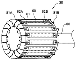
図3に示すように、外部電極62Aは、ケーブル80の導線81Aと接続され、外部電極62Bはケーブル80の導線81Bと接続されている。
図4に示すように、超音波を送受信する基本単位であるエレメント60は、第1の主面60SAと、第1の主面60SAと対向する第2の主面60SBと、を有する。そして、エレメント60の第1の主面60SAの略中央部には超音波を送受信する送受信部61が形成されており、第1の主面60SAの両端部には外部電極62A、62Bが配設されている。後述するように、エレメント60は複数の超音波振動子セル(以下、「セル」という)9を有する。
図5に示すように、エレメント60のセル9は、基体であるシリコン基板10上に、順に積層された、下部電極層11と、下部絶縁層12と、キャビティ13と、その支持層14と、上部絶縁層15と、上部電極層16と、保護層17と、を有する。なお、図5は1個のセル9の断面構造で示しているが、一般的には数十個~数千個のセル9が1個のエレメント60を構成している。
下部電極層11は、複数の下部電極11Aと、下部電極11Aの縁辺部から延設している複数の下部電極配線(不図示)と、を有する。下部電極層11は、同じエレメント60の他のセル9の下部電極11Aを接続している。上部電極層16は、複数の上部電極16Aと、上部電極16Aから延設している複数の上部電極配線(不図示)と、を有する。上部電極層16は、同じエレメント60の他のセル9の上部電極16Aを接続している。そして、それぞれのセル9は、キャビティ13を介して対向配置している下部電極11Aと上部電極16Aとを有する。
以上の説明のように、同じエレメント60に配置された複数のセル9の全ての下部電極11Aは互いに接続されており、全ての上部電極16Aも互いに接続されている。そして下部電極層11には、駆動電圧が印加され、上部電極層16は接地電位となっている。
エレメント60の下部電極層11と上部電極層16との間にパルス電圧が印加されると、静電力により上部電極16Aを含むメンブレン(振動部)18が振動することで、超音波が発生する。また外部から超音波が入射するとメンブレン18が変形し下部電極層11と上部電極層16との間隔が変化するため、静電容量の変化から超音波を電気信号に変換する。
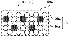
図6に示すように、超音波ユニット30では、エレメント60のN個のセル9は、N1a個の第1のセル9Aと、N2a個の第2のセル9Bと、を含む(但し、N1a≠N2a)。第2のセル9Bは、第1のセル9Aよりも受信感度が高く送信感度が低い。すなわち、第1のセル9Aが送信感度ST1a、受信感度SR1aであり、第2のセル9Bが送信感度ST2a(但し、ST1a>ST2a)、受信感度SR2a(但し、SR1a<SR2a)である。セル9の送信感度および受信感度は、例えば、メンブレン18の厚さを変えることで、送信または受信に最適化することができる。
以下、超音波ユニット30(エレメント60)の送受信感度Sを、送信感度ST(単位:Pa/V)と受信感度SR(単位:V/Pa)との積と定義し、送受信感度Sが最大となる条件を理論的に導きだす。
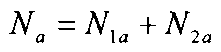
エレメント60のセル9の総数Na、セル9Aの個数N1a、セル9Bの個数N2aは、以下の(式11)で示される。
(式11)
 そして、エレメント60の送信感度STaは、(式12)で示される。
(式12)
 一方、エレメント60の受信感度SRaは、(式13)で示される。
(式13)
 すなわち、超音波ユニット30(エレメント60)では、送信感度が高く受信感度の低い第1のセル9Aおよび送信感度が低く受信感度が高い第2のセル9Bが、共に、送信および受信に使用される。
既に説明したように、エレメント60の送受信感度Saは、(式14)で定義される。
(式14)
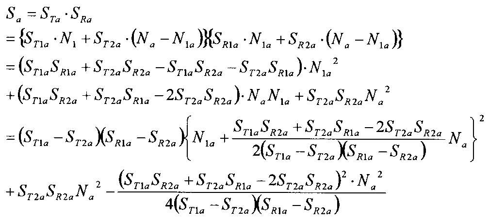 (式14)より、最大の送受信感度Saとなる第1のセル9Aの数N1aは、(式15)で示される。
(式15)
 なお、最大の送受信感度Saとなる第2のセル9Bの数N2aは、(式16)で示される。
(式16)
 すなわち、第1のセル9Aの数N1aが(式15)に示すように、第2のセル9Bの数N2aが(式16)に示すように構成されたエレメント60は送受信感度Saが最大となる。
以上の説明のように、超音波ユニット30は、送信に適した第1のセル9Aと受信に適した第2のセル9Bとの両方を用いて、送信および受信を行う。このため、送信に適した第1のセル9Aだけを用いて送信を行う従来の超音波ユニットよりも送信感度が高い。同様に受信に適した第2のセル9Bだけを用いて受信を行う従来の超音波ユニットよりも受信感度が高い。
さらに、(式15)で示される数の第1のセル9A、および(式16)で示される数の第2のセル9Bを有する超音波ユニット30は、送受信感度が高い。そして、超音波ユニット30を具備する超音波内視鏡2は送受信感度が高い。
なお、セル9の数(比率)は、厳密に(式15)等で示される数に限定されるものではなく、エレメント内での配置等の関係から、(式15)等で示される数から±10%の範囲内であればよい。
すなわち、(式15)で示される数(X)に対して、第1のセル9Aの数N1aは以下の(式15A)を満たしていればよい。
(式15A)
0.9X≦N1a≦1.1X
以下、具体例として、ST2a=1/2ST1a、SR2a=3SR1aの場合について例示する。
0.9X≦N1a≦1.1X
以下、具体例として、ST2a=1/2ST1a、SR2a=3SR1aの場合について例示する。
(式15)および(式16)より、第1のセル9Aの数N1a、第2のセル9Bの数N2aは(式17)、(式18)のようになる。
(式17)
 (式18)
(式18)
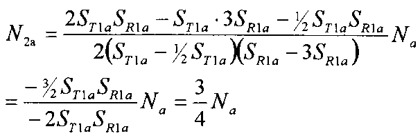 すなわち、エレメント60の複数のセル9の個数を、25%が第1のセル9A、75%が第2のセル9Bとなるように設定することで、送受信効率は最大となる。
なお、第1のセル9Aの個数N1aが、複数のセル9の個数Naの22.5%(25×0.9)以上27.5%(25×1.1)以下であれば、効果があることは既に説明した通りである。
<第2実施形態>
次に、第2実施形態の超音波ユニット30bおよび超音波内視鏡2bについて説明する。超音波ユニット30b等は、超音波ユニット30等と類似しているので、同じ構成要素には同じ符号を付し説明は省略する。
次に、第2実施形態の超音波ユニット30bおよび超音波内視鏡2bについて説明する。超音波ユニット30b等は、超音波ユニット30等と類似しているので、同じ構成要素には同じ符号を付し説明は省略する。
超音波ユニット30bのエレメント60bでは、個数N1bの第1のセル9Abが占有面積A1bの送信専用セルであり、個数N2bの第2のセル9Bbが占有面積A2b(但し、A1b≠A2b)の受信専用セルである。
すなわち、超音波ユニット30bでは、エレメント60bに配置された駆動電位電極である第1のセル9Abの下部電極と第2のセル9Bbの下部電極とは接続されていない。なお、接地電位電極である第1のセル9Abの上部電極と第2のセル9Bbの上部電極とは接続されていてもよい。
エレメント60bにおいて第1のセル9Abおよび第2のセル9Bbを配置する送受信部61の面積をA、エレメント60bを構成する超音波セルの数の総和をNbとおくと(式21)および(式22)の関係が成り立つ。
(式21)
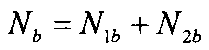 (式22)
(式22)
 すなわち、セル9bの占有面積とは、例えば個々のキャビティの直径等を意味するものではなく、図7に示すように、エレメント60に配置した場合の中心と周囲の他のセル9bの中心との中間点を結ぶ線で囲まれる部分の面積である。
(式22)を変形すると(式23)となる。
(式23)
 第1のセル9Abの送信感度をSTb、第2のセル9Bbの受信感度をSRbとすると、エレメント60bの送受信感度Sbは、(式24)で示される。
(式24)
 (式24)から、第1のセル9Abの数N1bが、(式25)を満たす場合に送受信感度Sbが最大となることが明らかである。
(式25)
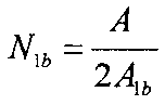 なお、この場合の第2のセル9Bbの数N2bは、(式26)で示される。
(式26)
 したがって、超音波セル9Ab、9Bbの数の比より(式27)が得られる。
(式27)
 (式22)および(式27)より、超音波セル9Ab、9Bbの数の関係は(式28)の通りとなる。
(式28)
 よって、超音波ユニット30bでは送受信感度Sbが最大となるのは、(式29)を満足する場合である。
(式29)
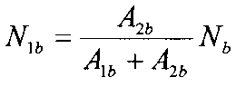 なお、送受信感度Sbが最大となる第2のセル9Bbの数N2bは、(式30)で示される。
(式30)
 また、セル9の数(比率)は、厳密に(式29)等で示される数に限定されるものではなく、エレメント内での配置等の関係から、(式29)等で示される数から±10%の範囲内であればよい。
すなわち、(式29)で示される数(Y)に対して、第1のセル9Abの数N1bは以下の(式29A)を満たしていればよい。
0.9Y≦N1b≦1.1Y (式29A)
以下、具体例として、第2のセル9Bbの面積A2bが第1のセル9Abの面積A1bの2倍、すなわちA2b=2A1bであった場合について説明する。(式29)および(式30)より、送受信感度Sbが最大第1のセル9Abの数N1b、第2のセル9Bbの数N2bは、(式31)、(式32)で示される。
以下、具体例として、第2のセル9Bbの面積A2bが第1のセル9Abの面積A1bの2倍、すなわちA2b=2A1bであった場合について説明する。(式29)および(式30)より、送受信感度Sbが最大第1のセル9Abの数N1b、第2のセル9Bbの数N2bは、(式31)、(式32)で示される。
(式31)
 (式32)
(式32)
 すなわち、エレメント60の複数のセル9の個数を、2/3が第1のセル9Aとし、1/3が第2のセル9Bとなるように設定することで、送受信効率は最大となる。
なお、第1のセル9Abの個数N1bが、複数のセル9の個数Nbの60%((2/3)×0.9)以上73.3%((2/3)×1.1)以下であれば効果があることは既に説明した通りである。
以上の説明のように、超音波ユニット30bは、送信専用の第1のセル9Abだけを用いて送信を行い、受信専用の第2のセル9Bbだけを用いて受信を行う。しかし、従来の超音波ユニットとは異なり、第1のセル9Abの占有面積A1bと、第2のセル9Bbの占有面積A2bと、が異なる。
上記で説明したように、送信専用セルおよび受信専用セルを有するエレメント60bでは、送受信感度の最大値となるセルの個数(比率)は、送信感度または受信感度は関係がない。
そして、それぞれのエレメント60bが(式31)、(式32)で示される数のセル9Ab、9Bbを有する超音波ユニット30bは、送受信感度が高い。そして、超音波ユニット30bを具備する超音波内視鏡2bは、送受信感度が高い。
<第3実施形態>
次に、第3実施形態の超音波ユニット30cおよび超音波内視鏡2cについて説明する。超音波ユニット30c等は、超音波ユニット30等と類似しているので、同じ構成要素には同じ符号を付し説明は省略する。
次に、第3実施形態の超音波ユニット30cおよび超音波内視鏡2cについて説明する。超音波ユニット30c等は、超音波ユニット30等と類似しているので、同じ構成要素には同じ符号を付し説明は省略する。
超音波ユニット30cのエレメント60cは、超音波セルが配置可能な部分の面積をAc、第1のセル9Acが送信感度ST1c、受信感度SR1c、面積がA1cであり、第2のセル9Acが、送信感度ST2c(但し、ST1c>ST2c)、受信感度SR2c(但し、SR1c<SR2c)、面積A2c(但し、A1c≠A2c)である。
すなわち、(式41)が成り立つ。
(式41)
 (式41)を変形すると、(式42)が得られる。
(式42)
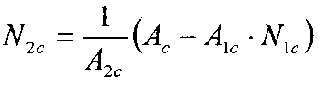 エレメント60cの送信感度STcは(式43)で示される。
(式43)
 一方、エレメント60cの受信感度SRcは(式44)で示される。
(式44)
 そして、エレメント60cの送受信感度Scは(式45)で示される。
(式45)
 ここで、α、β、γを、以下のように定義する。
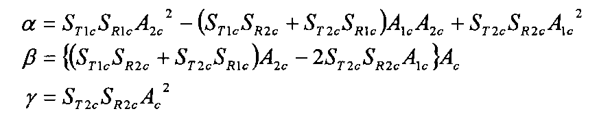
(式46)
 (式46)から、第1のセル9Acの数N1cが(式47)を満たす場合に、送受信感度Scは最大となることは明らかである。
(式47)
 一方、送受信感度Scは最大となる第2のセル9Bcの数N2cは、(式48)で示される。
(式48)
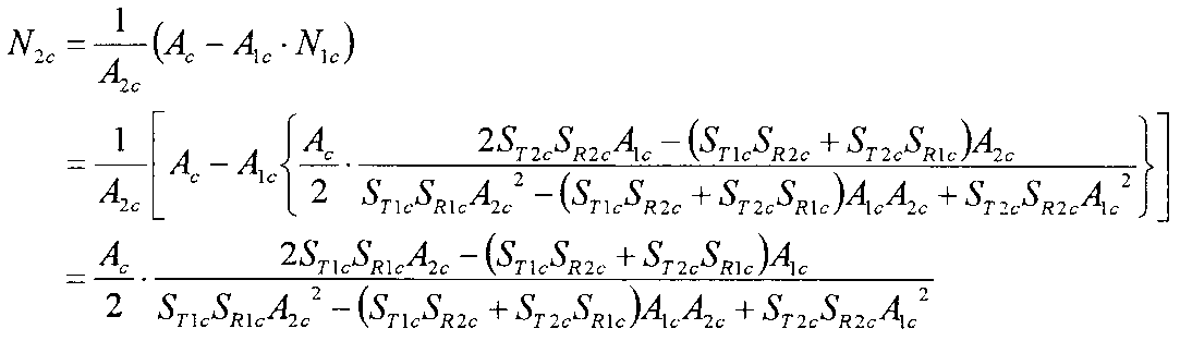 したがって、それぞれのセルの数の比より(式49)が得られる。
(式49)
 エレメント60cを構成するセルの数の総和をNcとすると(式50)および(式51)が成り立つ。
(式50)
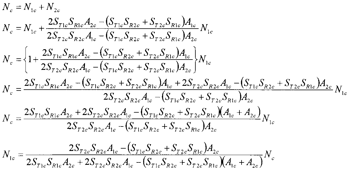 (式51)
(式51)
 第1のセル9Acの数NTcおよび第2のセル9Bcの数NRcが、(式50)および(式51)を満たすエレメント60c(超音波ユニット30c)は送受信感度Scが最大となる。
また、セル9の数(比率)は、厳密に(式50)等で示される数に限定されるものではなく、エレメント内での配置等の関係から、(式50)等で示される数から±10%の範囲内であればよい。
すなわち、(式50)で示される数(Z)に対して、第1のセル9Acの数N1cは以下の(式50A)を満たしていればよい。
Z・0.9≦N1c≦Z・1.1 (式50A)
例えば、Nc=1000、送信感度ST1c=100Pa/V、送信感度ST2c=20Pa/V、受信感度SR1c=300pV/Pa、受信感度SR2c=900pV/Pa、面積Ac=4.2mm2、面積A1c=4000μm2、A2c=5000μm2の場合は、N1c=800、N2c=200、となる。
例えば、Nc=1000、送信感度ST1c=100Pa/V、送信感度ST2c=20Pa/V、受信感度SR1c=300pV/Pa、受信感度SR2c=900pV/Pa、面積Ac=4.2mm2、面積A1c=4000μm2、A2c=5000μm2の場合は、N1c=800、N2c=200、となる。
なお、第1のセル9Acの個数N1cが、720(800×0.9)以上880(800×1.1)以下であれば効果があることは既に説明した通りである。
超音波ユニット30cは、超音波ユニット30、30bの効果を併せ持つため、送受信感度が、より高い。そして超音波ユニット30cを具備する超音波内視鏡2cは送受信感度が、より高い。
本発明は、上述した実施形態等に限定されるものではなく、本発明の要旨を変えない範囲において、種々の変更、改変等が可能である。
本出願は、2012年6月11日に日本国に出願された特願2012-132026号を優先権主張の基礎として出願するものであり、上記の開示内容は、本願明細書、請求の範囲、図面に引用されたものとする。
Claims (6)
- 下部電極とメンブレンを構成する上部電極とがキャビティを介して対向配置しているN個の超音波振動子セルを含む複数の超音波振動子エレメントを具備し、
前記超音波振動子エレメントが、N1個の第1の超音波振動子セルと、前記第1の超音波振動子セルよりも受信感度が高く送信感度の低いN2個(但し、N1≠N2、N1+N2=N)の第2の超音波振動子セルを有することを特徴とする超音波ユニット。 - 前記第1の超音波振動子セルの上部電極と前記第2の超音波振動子セルの上部電極とが接続されており、前記第1の超音波振動子セルの下部電極と前記第2の超音波振動子セルの下部電極とが接続されており、前記第1の超音波振動子セルおよび前記第2の超音波振動子セルが送信および受信に使用されることを特徴とする請求項1に記載の超音波ユニット。
- 前記第1の超音波振動子セルが送信感度ST1、受信感度SR1であり、前記第2の超音波振動子セルが送信感度ST2(但し、ST1>ST2)、受信感度SR2(但し、SR1<SR2)であり、以下の式を満足することを特徴とする請求項2に記載の超音波ユニット。
0.9X≦N1≦1.1X
但し、

- 前記第1の超音波振動子セルが面積A1の送信専用セルであり、前記第2の超音波振動子セルが面積A2(但し、A1≠A2)の受信専用セルであり、以下の式を満足することを特徴とする請求項1に記載の超音波ユニット。
0.9Y≦N1≦1.1Y
但し、

- 前記第1の超音波振動子セルが送信感度ST1、受信感度SR1、面積がA1であり、前記第2の超音波振動子セルが、送信感度ST2(但し、ST1>ST2)、受信感度SR2(但し、SR1<SR2)、面積A2(但し、A1≠A2)であり、以下の式を満足することを特徴とする請求項2に記載の超音波ユニット。
0.9Z≦N1≦1.1Z
但し、

- 請求項1から請求項5のいずれか1項に記載の超音波ユニットを有する先端部を具備することを特徴とする超音波内視鏡。
Priority Applications (4)
| Application Number | Priority Date | Filing Date | Title |
|---|---|---|---|
| CN201380030605.9A CN104349722B (zh) | 2012-06-11 | 2013-05-10 | 超声波部件以及超声波内窥镜 |
| JP2014521024A JP5927294B2 (ja) | 2012-06-11 | 2013-05-10 | 超音波ユニットおよび超音波内視鏡 |
| EP13804607.3A EP2859852A4 (en) | 2012-06-11 | 2013-05-10 | ULTRASONIC UNIT AND ULTRASOUND DOSCOPE |
| US14/565,952 US10034654B2 (en) | 2012-06-11 | 2014-12-10 | Ultrasound unit and ultrasound endoscope |
Applications Claiming Priority (2)
| Application Number | Priority Date | Filing Date | Title |
|---|---|---|---|
| JP2012132026 | 2012-06-11 | ||
| JP2012-132026 | 2012-06-11 |
Related Child Applications (1)
| Application Number | Title | Priority Date | Filing Date |
|---|---|---|---|
| US14/565,952 Continuation US10034654B2 (en) | 2012-06-11 | 2014-12-10 | Ultrasound unit and ultrasound endoscope |
Publications (1)
| Publication Number | Publication Date |
|---|---|
| WO2013187158A1 true WO2013187158A1 (ja) | 2013-12-19 |
Family
ID=49757990
Family Applications (1)
| Application Number | Title | Priority Date | Filing Date |
|---|---|---|---|
| PCT/JP2013/063173 Ceased WO2013187158A1 (ja) | 2012-06-11 | 2013-05-10 | 超音波ユニットおよび超音波内視鏡 |
Country Status (5)
| Country | Link |
|---|---|
| US (1) | US10034654B2 (ja) |
| EP (1) | EP2859852A4 (ja) |
| JP (1) | JP5927294B2 (ja) |
| CN (1) | CN104349722B (ja) |
| WO (1) | WO2013187158A1 (ja) |
Families Citing this family (3)
| Publication number | Priority date | Publication date | Assignee | Title |
|---|---|---|---|---|
| EP3229979B1 (en) * | 2014-12-11 | 2018-04-04 | Koninklijke Philips N.V. | Catheter transducer with staggered columns of micromachined ultrasonic transducers |
| CN109925004A (zh) * | 2017-12-19 | 2019-06-25 | 苏州国科昂卓医疗科技有限公司 | 一种超声内窥探头和具有其的超声内窥导管及成像装置 |
| JP7366239B2 (ja) * | 2020-03-26 | 2023-10-20 | 富士フイルム株式会社 | 超音波内視鏡 |
Citations (6)
| Publication number | Priority date | Publication date | Assignee | Title |
|---|---|---|---|---|
| JPH03165749A (ja) * | 1989-11-24 | 1991-07-17 | Aloka Co Ltd | 超音波探触子 |
| JP2002336248A (ja) * | 2001-05-14 | 2002-11-26 | Aloka Co Ltd | 超音波探触子 |
| JP2005210264A (ja) | 2004-01-21 | 2005-08-04 | Fujitsu Ltd | 光受信器及び光伝送装置 |
| JP2011025055A (ja) * | 2010-08-23 | 2011-02-10 | Olympus Corp | 静電容量型超音波振動子 |
| JP2012132026A (ja) | 2006-07-18 | 2012-07-12 | Arakawa Chem Ind Co Ltd | 導電性高分子/ドーパント錯体有機溶媒分散体の製造方法 |
| JP2013034665A (ja) * | 2011-08-08 | 2013-02-21 | Olympus Medical Systems Corp | 超音波エレメントおよび超音波内視鏡 |
Family Cites Families (8)
| Publication number | Priority date | Publication date | Assignee | Title |
|---|---|---|---|---|
| JPH10294995A (ja) * | 1997-04-21 | 1998-11-04 | Matsushita Electric Ind Co Ltd | 防滴型超音波送信器 |
| US6314057B1 (en) * | 1999-05-11 | 2001-11-06 | Rodney J Solomon | Micro-machined ultrasonic transducer array |
| US6585653B2 (en) * | 2001-07-31 | 2003-07-01 | Koninklijke Philips Electronics N.V. | Micro-machined ultrasonic transducer (MUT) array |
| US20070299345A1 (en) * | 2004-10-27 | 2007-12-27 | Hideo Adachi | Capacitive Ultrasonic Transducer and Endo Cavity Ultrasonic Diagnosis System Using the Same |
| DE602005006419T2 (de) * | 2005-09-14 | 2008-09-25 | Esaote S.P.A. | Elektroakustischer Wandler für Hochfrequenzanwendungen |
| JP5024989B2 (ja) * | 2007-01-23 | 2012-09-12 | 株式会社東芝 | 2次元アレイ超音波プローブ及び超音波診断システム |
| JP4891182B2 (ja) * | 2007-08-28 | 2012-03-07 | オリンパスメディカルシステムズ株式会社 | 超音波トランスデューサ、超音波診断装置及び超音波顕微鏡 |
| JP5511260B2 (ja) * | 2009-08-19 | 2014-06-04 | キヤノン株式会社 | 容量型電気機械変換装置、及びその感度調整方法 |
-
2013
- 2013-05-10 CN CN201380030605.9A patent/CN104349722B/zh active Active
- 2013-05-10 JP JP2014521024A patent/JP5927294B2/ja not_active Expired - Fee Related
- 2013-05-10 EP EP13804607.3A patent/EP2859852A4/en not_active Withdrawn
- 2013-05-10 WO PCT/JP2013/063173 patent/WO2013187158A1/ja not_active Ceased
-
2014
- 2014-12-10 US US14/565,952 patent/US10034654B2/en active Active
Patent Citations (6)
| Publication number | Priority date | Publication date | Assignee | Title |
|---|---|---|---|---|
| JPH03165749A (ja) * | 1989-11-24 | 1991-07-17 | Aloka Co Ltd | 超音波探触子 |
| JP2002336248A (ja) * | 2001-05-14 | 2002-11-26 | Aloka Co Ltd | 超音波探触子 |
| JP2005210264A (ja) | 2004-01-21 | 2005-08-04 | Fujitsu Ltd | 光受信器及び光伝送装置 |
| JP2012132026A (ja) | 2006-07-18 | 2012-07-12 | Arakawa Chem Ind Co Ltd | 導電性高分子/ドーパント錯体有機溶媒分散体の製造方法 |
| JP2011025055A (ja) * | 2010-08-23 | 2011-02-10 | Olympus Corp | 静電容量型超音波振動子 |
| JP2013034665A (ja) * | 2011-08-08 | 2013-02-21 | Olympus Medical Systems Corp | 超音波エレメントおよび超音波内視鏡 |
Non-Patent Citations (1)
| Title |
|---|
| See also references of EP2859852A4 |
Also Published As
| Publication number | Publication date |
|---|---|
| CN104349722B (zh) | 2016-08-31 |
| CN104349722A (zh) | 2015-02-11 |
| EP2859852A1 (en) | 2015-04-15 |
| US20150087993A1 (en) | 2015-03-26 |
| US10034654B2 (en) | 2018-07-31 |
| JPWO2013187158A1 (ja) | 2016-02-04 |
| EP2859852A4 (en) | 2016-03-02 |
| JP5927294B2 (ja) | 2016-06-01 |
Similar Documents
| Publication | Publication Date | Title |
|---|---|---|
| EP2110186B1 (en) | Ultrasound transducer and electronic device | |
| CN107708576B (zh) | 超声波振子和超声波探头 | |
| US10342511B2 (en) | Ultrasound transducer element and ultrasound endoscope | |
| JP5153972B2 (ja) | 超音波振動子および超音波診断装置 | |
| US9629609B2 (en) | Ultrasound element and ultrasound endoscope | |
| JPWO2013114968A1 (ja) | 超音波振動子アレイ、超音波振動子アレイの製造方法、及び超音波内視鏡 | |
| JP5927294B2 (ja) | 超音波ユニットおよび超音波内視鏡 | |
| JP5669953B2 (ja) | 超音波振動子エレメントおよび超音波内視鏡 | |
| JP5719275B2 (ja) | 超音波内視鏡システム | |
| JP2013034665A (ja) | 超音波エレメントおよび超音波内視鏡 | |
| JP2009050560A (ja) | 超音波トランスデューサ、超音波診断装置及び超音波顕微鏡 | |
| JPWO2016009689A1 (ja) | 超音波内視鏡 | |
| US9636710B2 (en) | Ultrasound element and ultrasound endoscope | |
| WO2014038238A1 (ja) | 超音波ユニット及び超音波内視鏡 | |
| JP2017164409A (ja) | 超音波プローブ | |
| JP2013150198A (ja) | 超音波エレメントおよび超音波プローブシステム | |
| JP6103991B2 (ja) | 超音波探触子および超音波内視鏡システム | |
| JP2013098581A (ja) | 超音波ユニット、超音波内視鏡、および超音波ユニットの製造方法 | |
| JP5893502B2 (ja) | 超音波観測装置および超音波観測装置の作動方法 | |
| JP2013026735A (ja) | 超音波エレメントおよび超音波内視鏡 | |
| JP2014068674A (ja) | 超音波エレメント及び超音波内視鏡 |
Legal Events
| Date | Code | Title | Description |
|---|---|---|---|
| 121 | Ep: the epo has been informed by wipo that ep was designated in this application |
Ref document number: 13804607 Country of ref document: EP Kind code of ref document: A1 |
|
| ENP | Entry into the national phase |
Ref document number: 2014521024 Country of ref document: JP Kind code of ref document: A |
|
| NENP | Non-entry into the national phase |
Ref country code: DE |
|
| WWE | Wipo information: entry into national phase |
Ref document number: 2013804607 Country of ref document: EP |