WO2013187204A1 - 3次元計測装置のための合成パラメータの生成装置 - Google Patents
3次元計測装置のための合成パラメータの生成装置 Download PDFInfo
- Publication number
- WO2013187204A1 WO2013187204A1 PCT/JP2013/064278 JP2013064278W WO2013187204A1 WO 2013187204 A1 WO2013187204 A1 WO 2013187204A1 JP 2013064278 W JP2013064278 W JP 2013064278W WO 2013187204 A1 WO2013187204 A1 WO 2013187204A1
- Authority
- WO
- WIPO (PCT)
- Prior art keywords
- camera
- unit
- grating
- phase
- grid
- Prior art date
- Legal status (The legal status is an assumption and is not a legal conclusion. Google has not performed a legal analysis and makes no representation as to the accuracy of the status listed.)
- Ceased
Links
Images



Classifications
-
- H—ELECTRICITY
- H04—ELECTRIC COMMUNICATION TECHNIQUE
- H04N—PICTORIAL COMMUNICATION, e.g. TELEVISION
- H04N13/00—Stereoscopic video systems; Multi-view video systems; Details thereof
- H04N13/10—Processing, recording or transmission of stereoscopic or multi-view image signals
- H04N13/106—Processing image signals
-
- G—PHYSICS
- G01—MEASURING; TESTING
- G01B—MEASURING LENGTH, THICKNESS OR SIMILAR LINEAR DIMENSIONS; MEASURING ANGLES; MEASURING AREAS; MEASURING IRREGULARITIES OF SURFACES OR CONTOURS
- G01B11/00—Measuring arrangements characterised by the use of optical techniques
- G01B11/24—Measuring arrangements characterised by the use of optical techniques for measuring contours or curvatures
- G01B11/25—Measuring arrangements characterised by the use of optical techniques for measuring contours or curvatures by projecting a pattern, e.g. one or more lines, moiré fringes on the object
-
- G—PHYSICS
- G01—MEASURING; TESTING
- G01B—MEASURING LENGTH, THICKNESS OR SIMILAR LINEAR DIMENSIONS; MEASURING ANGLES; MEASURING AREAS; MEASURING IRREGULARITIES OF SURFACES OR CONTOURS
- G01B11/00—Measuring arrangements characterised by the use of optical techniques
- G01B11/24—Measuring arrangements characterised by the use of optical techniques for measuring contours or curvatures
- G01B11/25—Measuring arrangements characterised by the use of optical techniques for measuring contours or curvatures by projecting a pattern, e.g. one or more lines, moiré fringes on the object
- G01B11/254—Projection of a pattern, viewing through a pattern, e.g. moiré
-
- G—PHYSICS
- G06—COMPUTING OR CALCULATING; COUNTING
- G06T—IMAGE DATA PROCESSING OR GENERATION, IN GENERAL
- G06T7/00—Image analysis
- G06T7/30—Determination of transform parameters for the alignment of images, i.e. image registration
-
- G—PHYSICS
- G06—COMPUTING OR CALCULATING; COUNTING
- G06T—IMAGE DATA PROCESSING OR GENERATION, IN GENERAL
- G06T7/00—Image analysis
- G06T7/50—Depth or shape recovery
- G06T7/521—Depth or shape recovery from laser ranging, e.g. using interferometry; from the projection of structured light
-
- H—ELECTRICITY
- H04—ELECTRIC COMMUNICATION TECHNIQUE
- H04N—PICTORIAL COMMUNICATION, e.g. TELEVISION
- H04N13/00—Stereoscopic video systems; Multi-view video systems; Details thereof
- H04N13/20—Image signal generators
- H04N13/282—Image signal generators for generating image signals corresponding to three or more geometrical viewpoints, e.g. multi-view systems
-
- G—PHYSICS
- G06—COMPUTING OR CALCULATING; COUNTING
- G06T—IMAGE DATA PROCESSING OR GENERATION, IN GENERAL
- G06T2207/00—Indexing scheme for image analysis or image enhancement
- G06T2207/10—Image acquisition modality
- G06T2207/10028—Range image; Depth image; 3D point clouds
Definitions
- the present invention relates to three-dimensional measurement, and more particularly to coordinate conversion between a plurality of measurement units.
- the inventor is developing an apparatus for measuring a three-dimensional shape of a measurement target such as a human body by a plurality of units including a camera and a projector.
- measurement data based on a coordinate system for each unit is converted into data based on a common coordinate system, and data for each unit is synthesized to obtain a target three-dimensional shape.
- Patent Document 1 Patent 44291305 discloses the following.
- the three-dimensional shape is measured by a phase shift method (for example, Patent Document 2: Patent 2903111).
- a sine wave pattern is projected from one of the two units by a projector, the pattern is moved by, for example, 1 ⁇ 4 wavelength of the sine wave, for example four times, and the phase of each pixel with respect to the sine wave is measured, and the target Measure the three-dimensional shape.
- the phase shift method when the phase is obtained, three-dimensional coordinates are obtained.
- the sine wave pattern projected by the projector is also photographed by another unit, and feature points are extracted based on the target shape data or texture.
- matching can be made with high accuracy by matching feature points between images taken by the two units and matching them with phases.
- the accuracy of coordinate conversion is limited.
- Patent Document 3 Japanese Patent Publication No. 3-58442 proposes a method of measuring a three-dimensional shape while keeping a sine wave pattern fixed without being moved. In this method, pixels corresponding to four images with pseudo-shifted patterns are created by extracting pixels from the captured image.
- Patent 4429135 Patent 2903111 3-58442
- An object of the present invention is to improve the accuracy of a composite parameter for coordinate conversion by enabling a large number of points at the same position to be sampled between images taken by cameras of different units. Another object of the present invention is to enable sampling of points at the same position accurately.
- the composite parameter generation apparatus includes a plurality of units including a projector that projects a periodic grating on a measurement target and a camera that captures the projected grating around the measurement target, and the measurement target surface for each unit.
- the first grid displayed on a predetermined reference plane is photographed with the camera of each unit for a three-dimensional measuring apparatus that measures the three-dimensional coordinates of the two and synthesizes the measured three-dimensional coordinates by coordinate conversion between the units.
- a synthesis parameter for the coordinate conversion is generated.
- the synthesis parameter generation apparatus of the present invention comprises: Means for storing, for each pixel of the camera, a phase with respect to the first grating, obtained from an image obtained by photographing the first grating with a camera of each unit; When the second grid is projected from the projector of each unit onto the reference plane, and the second grid is photographed by the camera of each unit, the three-dimensional coordinates of the reference plane in the coordinate system for each camera are displayed for each camera pixel.
- the synthesis parameter is generated so that the points having the same phase relative to the first grating are the same position. Although it is a point at the same position, there is rarely a pixel corresponding to the same position between different cameras. Therefore, subpixels are generated so that the phases match between the cameras. Since the number of sub-pixels can be generated as many as the number of pixels, for example, a large number of sub-pixels having the same phase can be generated between the cameras. Therefore, the accuracy of the composite parameter for coordinate transformation increases.
- the synthesis parameter generation device may be a part of the 3D measurement device or a device different from the 3D measurement device, and the function of the 3D measurement device can be borrowed when the synthesis parameter is generated. For example, obtaining the phase with respect to the first grating for each pixel of the camera is a part of the function of the three-dimensional measurement apparatus. Obtaining the three-dimensional coordinates of the reference plane is also a part of the function of the three-dimensional measuring apparatus.
- the reference surface is, for example, a flat surface, but may be a curved surface or the like.
- the pixel of the camera means not all the pixels of the camera but the pixels used for generating the synthesis parameter in the camera image.
- the predetermined reference plane is, for example, a screen such as a liquid crystal monitor, a white plate, a plate on which the first grid is drawn, or the like, as long as the first grid can be displayed in any sense.
- the first grating is a grating displayed on a screen of a liquid crystal monitor or the like, a grating projected from a projector or the like of a three-dimensional measuring apparatus, or a grating drawn on a reference plane, and the phase is obtained by photographing with a camera. Anything that can do.
- the synthesis parameter generation apparatus shifts the first grating by 1/3 pitch or less of the period of the grating, preferably by 1/4 pitch, and at each position where the first grating is shifted, It is configured to photograph the lattice. In this way, the phase of each pixel can be obtained from a plurality of images obtained by shifting the first lattice.
- a flat panel display that displays the first grid with the screen as a reference plane is provided. In this way, the first grid can be accurately displayed and shifted.
- the synthesis parameter generation apparatus includes each camera for the first grid from a plurality of second images obtained by regularly extracting pixels from different positions from an image obtained by capturing the first grid without shifting. It is comprised so that the phase for every pixel may be calculated
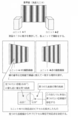
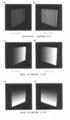
- FIG. 4 is a diagram illustrating a phase calculation process in the embodiment, in which a) is a lattice image captured by the unit 4-1, b) is a lattice image captured by the unit 4-2, and c) is a unit 4-1 x) phase image, d) x-phase image at unit 4-2, e) y-phase image at unit 4-1, and f) unit 4-2.
- the image of the phase of y direction is shown.
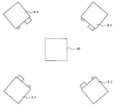
- the top view which shows arrangement
- Reference numeral 1 denotes an object whose three-dimensional shape is to be measured, such as a human body, furniture, a machine, an automobile, and a building.
- Four or three units 4 are arranged so as to surround the object 1, and each unit 4 includes a projector 6 and a digital camera 8.
- the projector 6 of the unit 4 projects a grid onto the object 1 and takes a picture with the camera 8.
- the unit 4 is controlled by the controller 10 and the image of the camera 8 is processed to obtain a set of three-dimensional coordinates on the surface of the object 1.
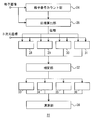
- the unit control unit 12 of the controller 10 controls the projection (light emission) and photographing of the grating from each unit 4, and the phase analysis unit 14 based on the digital image from each camera 8,
- the phase ⁇ (0 to 2 ⁇ ) within one pitch is obtained.
- the three-dimensional coordinate calculation unit 16 converts the phase of 2 ⁇ period into the phase from the grid reference point (2n ⁇ + ⁇ : n is an integer), and obtains the target three-dimensional coordinate (xyz) from the phase and the pixel position. . Since the coordinates obtained in this way are based on the coordinate system for each camera 8, the coordinate conversion unit 18 converts the coordinates into three-dimensional coordinates in an appropriate reference coordinate system.
- the synthesizing unit 20 averages a plurality of three-dimensional coordinates using the reliability depending on the pixel position as a weight, and outputs a set of three-dimensional coordinates of the surface of the target 1 in the reference coordinate system.
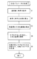
- the synthesis parameter generation algorithm is shown in FIG. 2, and the configuration of the synthesis parameter generation device 22 is shown in FIG.
- the first grid is displayed on the reference plane (step 1), and the phase with respect to the first grid is obtained for each pixel of the camera 8 (step 2).
- the second grid is projected from the projector 6 onto the reference plane, photographed by the camera 8, and the three-dimensional coordinate calculation unit 16 obtains the three-dimensional coordinates of each pixel (step 3).
- the phase and three-dimensional coordinates with respect to the first grating are obtained for each pixel of the camera 8. Since there are few pixels whose phases completely match between the cameras, sub-pixels are generated so that the phases match, and three-dimensional coordinates are also interpolated (step 4). Then, a large number of subpixels whose phases are completely coincided between the cameras and whose three-dimensional coordinates are known in the coordinate system of each camera are generated, and a synthesis parameter is generated using these subpixels (step 5).
- FIG. 3 shows the configuration of the synthesis parameter generation device 22, and the lattice number counting unit 24 counts the number of the lattice from the end portion of the first lattice, for example.
- the phase calculation unit 26 calculates the phase with respect to the first grating
- the phase analysis unit 14 may calculate the phase. Since the lattice number and the phase relative to the lattice are known by the processing so far, the complete phase of 2n ⁇ + ⁇ (n is the number of the lattice, ⁇ is a phase of 0 or more and less than 2 ⁇ ) is known, and this is calculated by the three-dimensional coordinate calculation unit 16. Are stored in the memories 28 to 31 in units of camera pixels.
- the first grating is displayed in the x direction (horizontal direction) and the y direction (vertical direction), and the phase for each is obtained, so there are two types of phases, the x direction and the y direction. Further, when a grating having striped brightness on the top, bottom, left and right is a first grating, two types of phases in the x direction and the y direction can be obtained from the same grating.
- sub-pixels having a predetermined phase such as 2n ⁇ + 0, 2n ⁇ + 1 / 4 ⁇ ,..., 2n ⁇ + 7 / 4 ⁇ , etc., are generated by the interpolation unit 32 by interpolation between surrounding pixels.
- the three-dimensional coordinates of the surrounding pixels are interpolated according to the interpolation ratio, and are stored in the memories 33 to 36 for each camera together with the phases in the x and y directions as the three-dimensional coordinates of the sub-pixels. Since the phase of the subpixel changes regularly, the phase is assigned to the addresses of the memories 33 to 36 and stored in a pseudo manner, and only the three-dimensional coordinates may be actually stored.
- the calculation unit 38 Since there are many pairs of sub-pixels having the same phase, the calculation unit 38 generates a synthesis parameter so that the sub-pixels having the same phase have the same three-dimensional coordinates.
- the parameters required for coordinate conversion are a three-dimensional translation vector accompanying the movement of the coordinate origin and a rotation matrix accompanying the rotation of the coordinate system (rotation angles are three types around the x axis, the y axis, and the z axis). .
- rotation angles are three types around the x axis, the y axis, and the z axis.
- Compositing parameters are those that convert the coordinates of one camera into the coordinates of the reference coordinate system using the coordinate system of any camera as the reference coordinate system, or the coordinate system independent of the camera as the reference coordinate system.
- the coordinates are converted into the coordinates of the reference coordinate system.
- Units 4-1 and 4-2 can shoot the same grid and units 4-2 and 4-3 can shoot the same grid, but units 4-1 and 4-3 can shoot the same grid. difficult. Therefore, for example, using the coordinate system of the camera of the unit 4-1 as a reference coordinate system, a synthesis parameter for converting the coordinate system of the camera of the unit 4-2 to the reference coordinate system is generated, and similarly, the camera 4 A synthesis parameter for converting the coordinate system to the reference coordinate system is generated.
- Synthesis parameters for converting the camera coordinate system of the unit 4-3 to the camera coordinate system of the unit 4-2, and for converting the camera coordinate system of the unit 4-3 to the coordinate system of the unit 4-4 Generating synthesis parameters.
- coordinate conversion is synthesized in the order of unit 4-3 ⁇ unit 4-2 ⁇ unit 4-1 and unit 4-3 ⁇ unit 4-4 ⁇ unit 4-1
- coordinate conversion from unit 4-3 to unit 4-1 For example, when these are averaged, a synthesis parameter for coordinate conversion from the unit 4-3 to the unit 4-1 can be generated.
- coordinate conversion may be performed in the order of unit 4-4 ⁇ unit 4-3 ⁇ unit 4-2 ⁇ unit 4-1, and unit 4-3 ⁇ unit 4-2 ⁇ unit 4-1 and unit 4- Coordinate conversion may be performed by two routes as in 4 ⁇ unit 4-1. It is arbitrary how the coordinate conversion between the units is combined to make the overall coordinate conversion.
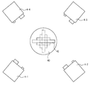
- FIG. 4 shows an example in which the first lattice is displayed using the liquid crystal panel 42.
- the liquid crystal panel instead of the liquid crystal panel, another flat panel monitor may be used.
- the panel 42 is placed on the turntable 40 and the orientation of the reference plane is 90 °. Rotate each one.
- a grid whose brightness changes in a sine wave shape in the x direction in each direction of the panel 42 and a grid whose brightness changes in a sine wave shape in the y direction are displayed, and the displayed grid is shifted by 1 ⁇ 4 of the pitch of the grid.
- images are taken by the camera of the unit 4 at each lattice position.
- the first grating may be projected from the projector of the unit 4.
- FIG. 5 shows an example in which a grid in the x direction is displayed in the situation of FIG. 4, and the images are taken by the adjacent units 4-1, 4-2 and the like.
- the number of the stripes of the grid is counted and the phase of each pixel with respect to the grid is obtained.
- a pixel having a phase of 2n ⁇ + 0.00 ° is searched for, for example, pixels having ⁇ 0.01 ° and + 0.59 ° are found.
- By performing the same processing in the y direction it is possible to generate a large number of subpixels having a predetermined value such as 2n ⁇ + 0.00 °, for example, in the x direction and the y direction.
- Fig. 6a) and b) show images obtained by photographing the first grid in the x direction displayed on the liquid crystal panel 42 with the cameras of the units 4-1 and 4-2 in the situation of Fig. 4.
- the phases in the x direction obtained from these images are shown in c) and d).
- the phase in the y direction obtained by displaying the first grid in the y direction on the liquid crystal panel 42 is shown in e) and f).
- the reference plane Since the position of the liquid crystal panel is measured by the unit 4, it is not necessary to arrange the reference plane at a known position. Similarly, the reference plane need not be a plane.
- FIG. 7 and 8 show a modification using a quadrangular prism reference object 50.
- lattices 52 are attached to four side surfaces of the reference object 50 by a rotating portion 54 so as to be rotatable by 90 °. .
- the lattice 52 is photographed by the cameras of two adjacent units, and the lattice 52 is rotated 90 ° and photographed again.
- the grating 52 does not shift, the phase with respect to the grating 52 can be obtained as in Patent Document 3.
- the three-dimensional coordinates of each point of the grid 52 can be obtained by projecting the second grid from the projector of the unit 4.
- the rotating unit 54 is unnecessary.
- FIG. 9 shows a second modification in which sinusoidal gratings 58 are drawn symmetrically on, for example, both surfaces of a transparent reference plate 56 having a constant thickness.
- a subpixel having a predetermined phase with respect to the grating 58a is generated, and its three-dimensional coordinates are obtained.
- subpixels having a predetermined phase with respect to the lattice 58b are generated, and three-dimensional coordinates are obtained.
- the gratings 58a and 58b are symmetric, if the three-dimensional coordinates of the sub-pixels with respect to the grating 58b are shifted in the thickness direction of the reference plate 56, the phase and the three-dimensional coordinates with reference to the grating 58a are changed in the unit 4-2. Can be treated as if acquired. Since the same lattice 58b can be observed between the units 4-2 and 4-3, the processing is further facilitated. Even in the above manner, the synthesis parameter can be generated. If the grid 58 is a vertical and horizontal striped grid, a rotating part or the like is unnecessary. When the grating 58 is a grating having only vertical stripes or horizontal stripes, it is preferable to obtain the horizontal phase and the vertical phase by the rotating unit 54 in FIG.
Landscapes
- Engineering & Computer Science (AREA)
- Physics & Mathematics (AREA)
- Computer Vision & Pattern Recognition (AREA)
- General Physics & Mathematics (AREA)
- Theoretical Computer Science (AREA)
- Optics & Photonics (AREA)
- Multimedia (AREA)
- Signal Processing (AREA)
- Length Measuring Devices By Optical Means (AREA)
- Image Processing (AREA)
Description
またこの発明の課題は、正確に同じ位置の点をサンプリングできるようにすることにある。
この発明の合成パラメータの生成装置は、
前記第1の格子を各ユニットのカメラで撮影した画像から求めた、第1の格子に対する位相をカメラの画素毎に記憶するための手段と、
基準面に各ユニットのプロジェクタから第2の格子を投影し、各ユニットのカメラで第2の格子を撮影した際の、カメラ毎の座標系での基準面の3次元座標をカメラの画素毎に記憶するための手段と、
カメラの画素毎の位相を補間して、カメラ間で位相が共通のサブピクセルを生成すると共に、カメラ毎の座標系での各サブピクセルの3次元座標を求めるための手段と、
各ユニット間で共通の基準座標系で、位相が同じサブピクセルの3次元座標がユニット間で一致するように、カメラ毎の座標系を各ユニット間で共通の基準座標系へ変換する合成パラメータを生成するための手段、とから成る。
6 プロジェクタ 8 カメラ 10 コントローラ
12 ユニット制御部 14 位相解析部
16 3次元座標算出部 18 座標変換部 20 合成部
22 合成パラメータ生成装置 24 格子番号カウント部
26 位相算出部 28~31 メモリ 32 補間部
33~36 メモリ 38 演算部 40 回転台
42 液晶パネル 50 基準物体 52 格子
54 回転部 56 基準板 58a,b 格子
Claims (4)
- 周期的な格子を測定対象へ投影するプロジェクタと投影された格子を撮影するカメラとから成るユニットを測定対象の周囲に複数備えて、ユニット毎に測定対象表面の3次元座標を計測し、計測した3次元座標をユニット間の座標変換により合成する3次元計測装置のために、所定の基準面に表示された第1の格子を各ユニットのカメラで撮影することにより、前記座標変換のための合成パラメータを生成する装置であって、
前記第1の格子を各ユニットのカメラで撮影した画像から求めた、第1の格子に対する位相をカメラの画素毎に記憶するための手段と、
基準面に各ユニットのプロジェクタから第2の格子を投影し、各ユニットのカメラで第2の格子を撮影した際の、カメラ毎の座標系での基準面の3次元座標をカメラの画素毎に記憶するための手段と、
カメラの画素毎の位相を補間して、カメラ間で位相が共通のサブピクセルを生成すると共に、カメラ毎の座標系での各サブピクセルの3次元座標を求めるための手段と、
各ユニット間で共通の基準座標系で、位相が同じサブピクセルの3次元座標がユニット間で一致するように、カメラ毎の座標系を各ユニット間で共通の基準座標系へ変換する合成パラメータを生成するための手段、とから成る3次元計測装置のための合成パラメータの生成装置。 - 前記第1の格子を格子の周期の1/3ピッチ以下の距離ずつシフトさせ、第1の格子をシフトさせる各位置毎に、第1の格子を撮影するように構成されていることを特徴とする、請求項1の3次元計測装置のための合成パラメータの生成装置。
- 画面を前記基準面として前記第1の格子を表示する、フラットパネルディスプレイを備えていることを特徴とする、請求項2の3次元計測装置のための合成パラメータの生成装置。
- シフトさせずに前記第1の格子を撮影した画像から、位置を変えて画素を規則的に抽出した複数の第2の画像から、第1の格子に対する各カメラの画素毎の位相を求めるように構成されていることを特徴とする、請求項1の3次元計測装置のための合成パラメータの生成装置。
Priority Applications (4)
| Application Number | Priority Date | Filing Date | Title |
|---|---|---|---|
| CN201380031267.0A CN104380036A (zh) | 2012-06-13 | 2013-05-22 | 用于三维测量装置的合成参数的生成装置 |
| US14/406,591 US20150181191A1 (en) | 2012-06-13 | 2013-05-22 | Synthesis-parameter generation device for three-dimensional measurement apparatus |
| EP13804805.3A EP2863166A4 (en) | 2012-06-13 | 2013-05-22 | SYNTHESIS PARAMETER GENERATION DEVICE FOR THREE-DIMENSIONAL MEASURING APPARATUS |
| JP2014521236A JPWO2013187204A1 (ja) | 2012-06-13 | 2013-05-22 | 3次元計測装置のための合成パラメータの生成装置 |
Applications Claiming Priority (2)
| Application Number | Priority Date | Filing Date | Title |
|---|---|---|---|
| JP2012133505 | 2012-06-13 | ||
| JP2012-133505 | 2012-06-13 |
Publications (1)
| Publication Number | Publication Date |
|---|---|
| WO2013187204A1 true WO2013187204A1 (ja) | 2013-12-19 |
Family
ID=49758034
Family Applications (1)
| Application Number | Title | Priority Date | Filing Date |
|---|---|---|---|
| PCT/JP2013/064278 Ceased WO2013187204A1 (ja) | 2012-06-13 | 2013-05-22 | 3次元計測装置のための合成パラメータの生成装置 |
Country Status (5)
| Country | Link |
|---|---|
| US (1) | US20150181191A1 (ja) |
| EP (1) | EP2863166A4 (ja) |
| JP (1) | JPWO2013187204A1 (ja) |
| CN (1) | CN104380036A (ja) |
| WO (1) | WO2013187204A1 (ja) |
Cited By (4)
| Publication number | Priority date | Publication date | Assignee | Title |
|---|---|---|---|---|
| WO2017154707A1 (ja) * | 2016-03-09 | 2017-09-14 | 株式会社ニコン | 検出装置、検出システム、検出方法、及び検出プログラム |
| JP2017530352A (ja) * | 2014-09-11 | 2017-10-12 | サイバーオプティクス コーポレーション | 三次元表面形状計測における多数のカメラ及び光源からの点群統合 |
| JP2018146348A (ja) * | 2017-03-03 | 2018-09-20 | 株式会社キーエンス | 三次元形状計測装置、三次元形状計測方法、及びコンピュータプログラム |
| JP2022505166A (ja) * | 2018-10-18 | 2022-01-14 | サイバーオプティクス コーポレーション | 対向配置チャネルを有する三次元センサ |
Families Citing this family (5)
| Publication number | Priority date | Publication date | Assignee | Title |
|---|---|---|---|---|
| WO2013187203A1 (ja) * | 2012-06-12 | 2013-12-19 | 株式会社島精機製作所 | 3次元計測装置と3次元計測方法 |
| US9817489B2 (en) * | 2014-01-27 | 2017-11-14 | Apple Inc. | Texture capture stylus and method |
| JP6677113B2 (ja) * | 2016-07-19 | 2020-04-08 | 富士通株式会社 | 電子機器の製造装置、及びケーブル形状推定プログラム |
| JP6308637B1 (ja) * | 2017-05-08 | 2018-04-11 | 国立大学法人福井大学 | 特徴量を用いた3次元計測方法およびその装置 |
| JP7177239B1 (ja) * | 2021-11-05 | 2022-11-22 | 株式会社ダイヘン | マーカ検出装置及びロボット教示システム |
Citations (8)
| Publication number | Priority date | Publication date | Assignee | Title |
|---|---|---|---|---|
| JPH0358442B2 (ja) | 1984-03-19 | 1991-09-05 | Oosaka Daigakucho | |
| JP2903111B1 (ja) | 1998-03-31 | 1999-06-07 | 和歌山大学長 | 形状変形計測方法 |
| JP2002341031A (ja) * | 2001-05-11 | 2002-11-27 | Daiei Dream Kk | レーザレーダを用いた三次元モデルの作成方法及び三次元スキャナシステム |
| JP2004108950A (ja) * | 2002-09-18 | 2004-04-08 | Ricoh Co Ltd | 光学式形状測定システム |
| JP2005189203A (ja) * | 2003-12-26 | 2005-07-14 | Fuji Xerox Co Ltd | 全周囲3dモデル作成方法および装置 |
| JP4291358B2 (ja) | 2006-12-13 | 2009-07-08 | 株式会社廣瀬製作所 | 水平半回転かま |
| JP4429135B2 (ja) | 2004-10-05 | 2010-03-10 | Necエンジニアリング株式会社 | 三次元形状計測システム及び計測方法 |
| JP2010145186A (ja) * | 2008-12-17 | 2010-07-01 | Topcon Corp | 形状測定装置およびプログラム |
Family Cites Families (5)
| Publication number | Priority date | Publication date | Assignee | Title |
|---|---|---|---|---|
| US6147760A (en) * | 1994-08-30 | 2000-11-14 | Geng; Zheng Jason | High speed three dimensional imaging method |
| JP2003269928A (ja) * | 2002-03-12 | 2003-09-25 | Nec Corp | 3次元形状計測方法および装置ならびにプログラム |
| DE102005061931B4 (de) * | 2005-12-23 | 2011-04-14 | Bremer Institut für angewandte Strahltechnik GmbH | Verfahren und Vorrichtung zur Kalibrierung einer optischen Einrichtung |
| KR100947463B1 (ko) * | 2007-08-31 | 2010-03-17 | 에스엔유 프리시젼 주식회사 | 엘시디를 이용한 삼차원 형상 측정장치 |
| CN102288131A (zh) * | 2011-05-12 | 2011-12-21 | 上海大学 | 物体360°轮廓误差的自适应条纹测量装置和方法 |
-
2013
- 2013-05-22 WO PCT/JP2013/064278 patent/WO2013187204A1/ja not_active Ceased
- 2013-05-22 JP JP2014521236A patent/JPWO2013187204A1/ja not_active Abandoned
- 2013-05-22 EP EP13804805.3A patent/EP2863166A4/en not_active Withdrawn
- 2013-05-22 CN CN201380031267.0A patent/CN104380036A/zh active Pending
- 2013-05-22 US US14/406,591 patent/US20150181191A1/en not_active Abandoned
Patent Citations (8)
| Publication number | Priority date | Publication date | Assignee | Title |
|---|---|---|---|---|
| JPH0358442B2 (ja) | 1984-03-19 | 1991-09-05 | Oosaka Daigakucho | |
| JP2903111B1 (ja) | 1998-03-31 | 1999-06-07 | 和歌山大学長 | 形状変形計測方法 |
| JP2002341031A (ja) * | 2001-05-11 | 2002-11-27 | Daiei Dream Kk | レーザレーダを用いた三次元モデルの作成方法及び三次元スキャナシステム |
| JP2004108950A (ja) * | 2002-09-18 | 2004-04-08 | Ricoh Co Ltd | 光学式形状測定システム |
| JP2005189203A (ja) * | 2003-12-26 | 2005-07-14 | Fuji Xerox Co Ltd | 全周囲3dモデル作成方法および装置 |
| JP4429135B2 (ja) | 2004-10-05 | 2010-03-10 | Necエンジニアリング株式会社 | 三次元形状計測システム及び計測方法 |
| JP4291358B2 (ja) | 2006-12-13 | 2009-07-08 | 株式会社廣瀬製作所 | 水平半回転かま |
| JP2010145186A (ja) * | 2008-12-17 | 2010-07-01 | Topcon Corp | 形状測定装置およびプログラム |
Non-Patent Citations (1)
| Title |
|---|
| See also references of EP2863166A4 |
Cited By (11)
| Publication number | Priority date | Publication date | Assignee | Title |
|---|---|---|---|---|
| JP2017530352A (ja) * | 2014-09-11 | 2017-10-12 | サイバーオプティクス コーポレーション | 三次元表面形状計測における多数のカメラ及び光源からの点群統合 |
| WO2017154707A1 (ja) * | 2016-03-09 | 2017-09-14 | 株式会社ニコン | 検出装置、検出システム、検出方法、及び検出プログラム |
| JPWO2017154707A1 (ja) * | 2016-03-09 | 2019-01-24 | 株式会社ニコン | 検出装置、検出システム、検出方法、及び検出プログラム |
| US11629950B2 (en) | 2016-03-09 | 2023-04-18 | Nikon Corporation | Detection device, detection system, detection method, and storage medium |
| US12203744B2 (en) | 2016-03-09 | 2025-01-21 | Nikon Corporation | Detection device, detection system, detection method, and storage medium |
| JP2018146348A (ja) * | 2017-03-03 | 2018-09-20 | 株式会社キーエンス | 三次元形状計測装置、三次元形状計測方法、及びコンピュータプログラム |
| JP2022505166A (ja) * | 2018-10-18 | 2022-01-14 | サイバーオプティクス コーポレーション | 対向配置チャネルを有する三次元センサ |
| US11604062B2 (en) | 2018-10-18 | 2023-03-14 | Cyberoptics Corporation | Three-dimensional sensor with counterposed channels |
| JP7413372B2 (ja) | 2018-10-18 | 2024-01-15 | サイバーオプティクス コーポレーション | 対向配置チャネルを有する三次元センサ |
| JP2024029135A (ja) * | 2018-10-18 | 2024-03-05 | サイバーオプティクス コーポレーション | 対向配置チャネルを有する三次元センサ |
| JP7640661B2 (ja) | 2018-10-18 | 2025-03-05 | サイバーオプティクス コーポレーション | 対向配置チャネルを有する三次元センサ |
Also Published As
| Publication number | Publication date |
|---|---|
| JPWO2013187204A1 (ja) | 2016-02-04 |
| EP2863166A1 (en) | 2015-04-22 |
| CN104380036A (zh) | 2015-02-25 |
| EP2863166A4 (en) | 2016-07-27 |
| US20150181191A1 (en) | 2015-06-25 |
Similar Documents
| Publication | Publication Date | Title |
|---|---|---|
| WO2013187204A1 (ja) | 3次元計測装置のための合成パラメータの生成装置 | |
| JP6016912B2 (ja) | 3次元計測装置と3次元計測方法 | |
| Feng et al. | Fast three-dimensional measurements for dynamic scenes with shiny surfaces | |
| JP5872923B2 (ja) | Ar画像処理装置及び方法 | |
| US9117278B2 (en) | System and method for geometric modeling using multiple data acquisition means | |
| US20150116691A1 (en) | Indoor surveying apparatus and method | |
| US20140253929A1 (en) | Apparatus and method for 3d surface measurement | |
| Dai et al. | A dual-frequency fringe projection three-dimensional shape measurement system using a DLP 3D projector | |
| JP2003269928A (ja) | 3次元形状計測方法および装置ならびにプログラム | |
| KR102550930B1 (ko) | 나안 3d 디스플레이의 이미지 오차 수정방법 및 장치 | |
| TWI573984B (zh) | 圖像匹配系統及方法 | |
| CN102184566A (zh) | 基于微型投影仪手机平台的便携式三维扫描系统及方法 | |
| CN110692084B (zh) | 用于导出场景的拓扑信息的装置和机器可读存储介质 | |
| WO2018179040A1 (ja) | カメラパラメータ推定装置、方法およびプログラム | |
| CN117315042B (zh) | 面向工业现场的结构光系统快速标定方法 | |
| JP2015021862A (ja) | 3次元計測装置及び3次元計測方法 | |
| CN100561118C (zh) | 三维数字化测量中的一种颜色渲染方法 | |
| JP2017116420A (ja) | データ処理装置およびその方法 | |
| JP2011075336A (ja) | 3次元形状計測装置、3次元形状計測方法 | |
| WO2018179039A1 (ja) | カメラパラメータ推定装置、方法およびプログラム | |
| WO2015188460A1 (zh) | 一种测量面积的装置和方法 | |
| CN104807405A (zh) | 一种基于光线角度标定的三维坐标测量方法 | |
| US20210183092A1 (en) | Measuring apparatus, measuring method and microscope system | |
| JP2019139030A (ja) | 3次元計測対象物体の表面に計測結果関連情報を投影する方法および装置 | |
| US7995098B2 (en) | Systems and methods for measuring spatial and angular performance of a visual display |
Legal Events
| Date | Code | Title | Description |
|---|---|---|---|
| 121 | Ep: the epo has been informed by wipo that ep was designated in this application |
Ref document number: 13804805 Country of ref document: EP Kind code of ref document: A1 |
|
| ENP | Entry into the national phase |
Ref document number: 2014521236 Country of ref document: JP Kind code of ref document: A |
|
| WWE | Wipo information: entry into national phase |
Ref document number: 14406591 Country of ref document: US |
|
| REEP | Request for entry into the european phase |
Ref document number: 2013804805 Country of ref document: EP |
|
| WWE | Wipo information: entry into national phase |
Ref document number: 2013804805 Country of ref document: EP |
|
| NENP | Non-entry into the national phase |
Ref country code: DE |