WO2013187291A1 - 積繊装置 - Google Patents
積繊装置 Download PDFInfo
- Publication number
- WO2013187291A1 WO2013187291A1 PCT/JP2013/065555 JP2013065555W WO2013187291A1 WO 2013187291 A1 WO2013187291 A1 WO 2013187291A1 JP 2013065555 W JP2013065555 W JP 2013065555W WO 2013187291 A1 WO2013187291 A1 WO 2013187291A1
- Authority
- WO
- WIPO (PCT)
- Prior art keywords
- opening
- accumulation
- defining
- recess
- fiber
- Prior art date
- Legal status (The legal status is an assumption and is not a legal conclusion. Google has not performed a legal analysis and makes no representation as to the accuracy of the status listed.)
- Ceased
Links
Images


Classifications
-
- A—HUMAN NECESSITIES
- A61—MEDICAL OR VETERINARY SCIENCE; HYGIENE
- A61F—FILTERS IMPLANTABLE INTO BLOOD VESSELS; PROSTHESES; DEVICES PROVIDING PATENCY TO, OR PREVENTING COLLAPSING OF, TUBULAR STRUCTURES OF THE BODY, e.g. STENTS; ORTHOPAEDIC, NURSING OR CONTRACEPTIVE DEVICES; FOMENTATION; TREATMENT OR PROTECTION OF EYES OR EARS; BANDAGES, DRESSINGS OR ABSORBENT PADS; FIRST-AID KITS
- A61F13/00—Bandages or dressings; Absorbent pads
- A61F13/15—Absorbent pads, e.g. sanitary towels, swabs or tampons for external or internal application to the body; Supporting or fastening means therefor; Tampon applicators
- A61F13/15577—Apparatus or processes for manufacturing
- A61F13/15617—Making absorbent pads from fibres or pulverulent material with or without treatment of the fibres
- A61F13/15658—Forming continuous, e.g. composite, fibrous webs, e.g. involving the application of pulverulent material on parts thereof
-
- A—HUMAN NECESSITIES
- A61—MEDICAL OR VETERINARY SCIENCE; HYGIENE
- A61F—FILTERS IMPLANTABLE INTO BLOOD VESSELS; PROSTHESES; DEVICES PROVIDING PATENCY TO, OR PREVENTING COLLAPSING OF, TUBULAR STRUCTURES OF THE BODY, e.g. STENTS; ORTHOPAEDIC, NURSING OR CONTRACEPTIVE DEVICES; FOMENTATION; TREATMENT OR PROTECTION OF EYES OR EARS; BANDAGES, DRESSINGS OR ABSORBENT PADS; FIRST-AID KITS
- A61F13/00—Bandages or dressings; Absorbent pads
- A61F13/15—Absorbent pads, e.g. sanitary towels, swabs or tampons for external or internal application to the body; Supporting or fastening means therefor; Tampon applicators
- A61F13/15577—Apparatus or processes for manufacturing
- A61F13/15707—Mechanical treatment, e.g. notching, twisting, compressing, shaping
- A61F13/15747—Folding; Pleating; Coiling; Stacking; Packaging
-
- A—HUMAN NECESSITIES
- A61—MEDICAL OR VETERINARY SCIENCE; HYGIENE
- A61F—FILTERS IMPLANTABLE INTO BLOOD VESSELS; PROSTHESES; DEVICES PROVIDING PATENCY TO, OR PREVENTING COLLAPSING OF, TUBULAR STRUCTURES OF THE BODY, e.g. STENTS; ORTHOPAEDIC, NURSING OR CONTRACEPTIVE DEVICES; FOMENTATION; TREATMENT OR PROTECTION OF EYES OR EARS; BANDAGES, DRESSINGS OR ABSORBENT PADS; FIRST-AID KITS
- A61F13/00—Bandages or dressings; Absorbent pads
- A61F13/15—Absorbent pads, e.g. sanitary towels, swabs or tampons for external or internal application to the body; Supporting or fastening means therefor; Tampon applicators
- A61F13/45—Absorbent pads, e.g. sanitary towels, swabs or tampons for external or internal application to the body; Supporting or fastening means therefor; Tampon applicators characterised by the shape
- A61F13/47—Sanitary towels, incontinence pads or napkins
- A61F13/472—Sanitary towels, incontinence pads or napkins specially adapted for female use
-
- A—HUMAN NECESSITIES
- A61—MEDICAL OR VETERINARY SCIENCE; HYGIENE
- A61F—FILTERS IMPLANTABLE INTO BLOOD VESSELS; PROSTHESES; DEVICES PROVIDING PATENCY TO, OR PREVENTING COLLAPSING OF, TUBULAR STRUCTURES OF THE BODY, e.g. STENTS; ORTHOPAEDIC, NURSING OR CONTRACEPTIVE DEVICES; FOMENTATION; TREATMENT OR PROTECTION OF EYES OR EARS; BANDAGES, DRESSINGS OR ABSORBENT PADS; FIRST-AID KITS
- A61F13/00—Bandages or dressings; Absorbent pads
- A61F13/15—Absorbent pads, e.g. sanitary towels, swabs or tampons for external or internal application to the body; Supporting or fastening means therefor; Tampon applicators
- A61F13/53—Absorbent pads, e.g. sanitary towels, swabs or tampons for external or internal application to the body; Supporting or fastening means therefor; Tampon applicators characterised by the absorbing medium
- A61F13/534—Absorbent pads, e.g. sanitary towels, swabs or tampons for external or internal application to the body; Supporting or fastening means therefor; Tampon applicators characterised by the absorbing medium having an inhomogeneous composition through the thickness of the pad
Definitions
- the present invention includes a rotating drum having a concave portion for accumulation on the outer peripheral surface, and a molded body material such as a fiber material or a water-absorbing polymer is sucked into the concave portion for accumulation to pile up a molded body (absorbent body) having a predetermined shape. It is related with the fiber pile apparatus used for obtaining.
- a rotating drum having a concave portion for accumulation on the outer peripheral surface, and pulp on the outer peripheral surface while rotating the rotating drum
- the molded body material is supplied in a scattered state, and the molded body material is stacked in the accumulation recess by suction from the bottom surface of the accumulation recess composed of a porous member having a plurality of suction holes formed.
- a fiber stacking apparatus that separates the piled material in the collecting concave portion from the collecting concave portion by suction from the sucking means disposed opposite to the collecting concave portion and transfers it onto the suction means.
- the portion where the molding material is stacked at a high basis weight and the molding material at a lower basis weight are stacked in the recesses for accumulation corresponding to the individual absorbers.
- Patent Document 1 discloses a bottom portion of a stacking recess formed of a metal mesh or the like in order to adjust the density and amount of the stacked fabric in the stacking recess. It is disclosed that the opening ratio (opening ratio) is varied.
- the suction chamber disposed inside the rotary drum is divided into a plurality of suction chambers in a longitudinal section along the flow direction, and each suction Provide suction means for each chamber, and make each suction force different (by sucking from the inner surface side, pile up the pulverized pulp carried on the air flow on the surface of the suction deposition part,
- the suction chamber disposed inside the fiber stack is partitioned into a plurality of suction chambers in a longitudinal section along the flow direction, and a suction unit is provided for each suction chamber. Textile device).
- an opening of the metal mesh is provided on the inner surface side (the non-stacking surface side of the molded body material) of the web layer made of a metal mesh (porous member) that forms the bottom surface of the concave portion for accumulation.
- rotating drums that are stacked in this order are described.
- Patent Document 4 a honeycomb structure rectifier that rectifies the air flow is integrated with the porous plate on the inner side of a gas-permeable porous plate that forms the bottom of the suction deposition portion and has a large number of suction holes.
- a fiber stacking device arranged in an automatic manner is described.
- the suction holes of the perforated plate are formed in a mortar shape from the surface side toward the inner side, and thereby the absorber raw material is completely fitted into the suction holes. It is said that the loss to the inside can be prevented and the loss of raw materials can be reduced.
- Patent Document 4 it is said that by using the fiber stacking device having such a configuration, the profile of the absorber is stabilized and variation in the weight of the absorber is suppressed.
- Patent Document 5 as a molded body manufacturing apparatus, a fixed drum whose inside is maintained at a negative pressure, and a rotation that rotates along the outer peripheral surface of the fixed drum and has a plurality of accumulation recesses on the outer peripheral surface.
- Each of the stacking recesses is divided into a plurality of unit stacking units that can be sucked independently of each other, and each unit stacking unit is configured to be capable of stacking by sucking the raw material for each unit stacking unit.
- suction ports corresponding to the respective unit accumulating portions are provided on the inner peripheral surface of the rotating drum, and suction ports are provided on the outer peripheral surface of the fixed drum.
- the collecting portion and the corresponding suction port are communicated with each other by a communication pipe.
- the suction port communicates with the suction port in each stacking recess.
- the unit accumulating unit is selectively sucked.
- JP 2000-234255 A Japanese Patent Laid-Open No. 2002-272784 JP-A-62-206071 US2008181511 (A1) JP 2000-178866 A
- the hole area ratio (the ratio of the total area of the suction holes to the unit area) at the bottom of the accumulation recess is appropriately set. Therefore, it is possible to control the amount of the molded body material (basis weight of the molded body) stacked on the bottom, and in general, when the porosity is reduced, the suction of the molded body material is reduced. The force decreases and the amount of piles decreases. Accordingly, by partially varying the opening ratio of the bottom of the stacking recess, even when suction is performed with a constant suction force from the inside of the apparatus using a single suction means, the suction force is relatively applied to the bottom portion.
- a strong strong suction portion and a weak suction portion having a relatively weak suction force are generated, and therefore, a high basis weight portion in which the molded body material is stacked at a relatively high basis weight on the strong suction portion, It is possible to produce a molded body having a low basis weight portion in which the molded body material is laminated at a relatively low basis weight on the weak suction portion, and the basis weight of the molded body with a relatively simple apparatus configuration. The amount can be adjusted.
- Patent Document 1 does not describe such uneven stacking caused by an intentional decrease in the opening ratio of the bottom of the accumulation recess, and does not cause uneven stacking. There has not yet been provided a fiber stacking device that can adjust the amount of fiber piles.
- Patent Document 3 has the following problems 1 to 3, and there is room for improvement.
- Problem 1 One small opening of the gas flow rate control layer is arranged so as to straddle a plurality of large openings of the space member, and there is a possibility that uneven fiber stacking may occur.
- Problem 2 The number of small openings of the gas flow rate control layer corresponding to each of the plurality of large openings of the space member is different, and there is a possibility that uneven fiber stacking may occur.
- Problem 3 The metal mesh (porous member) is formed with pockets (recesses) for partially forming the molded body material into a high basis weight, and the gas flow control layer surrounds the pocket region. Since the end portion is disposed so as to straddle the plurality of openings of the space member, there is a possibility that a high basis weight portion (so-called middle-high portion) as designed cannot be formed. is there.
- the technique described in Patent Document 4 is mainly aimed at stabilizing the profile of the absorbent body, and does not correspond to making the basis weight of each part of the absorbent body adjustable as in the technique described in Patent Document 2. .
- the technique described in Patent Document 2 can adjust the basis weight of each part of the absorber, but requires a plurality of suction means for sucking each of the plurality of chambers. There is a risk that the cost will rise. Further, the technique described in Patent Document 2 cannot change the suction force by the suction chamber in the flow direction (circumferential direction or rotation direction of the rotating drum), and the product of uniform basis weight in the flow direction. Since only fiber is possible, there is little variation in the basis weight distribution, and there is a possibility that various requests for the absorbent body cannot be sufficiently met.
- the technique described in Patent Document 2 is a non-rotating partition that divides a collecting recess rotatably disposed on the outer peripheral surface of a rotating drum and a suction chamber disposed inside the rotating drum into a plurality of regions.
- a gap is easily formed between the wall and an air flow leaks from the gap, and thus there is a possibility that the designed basis weight difference cannot be obtained in the absorbent body.
- the technique described in Patent Document 5 only when the suction port of the rotating drum and the suction port of the fixed drum overlap, a part of the accumulation recess communicated with the suction port selectively sucks and holds the raw material.
- the present invention (first invention) has an accumulation concave portion on which the molded material is piled on the outer surface, and rides on the air flow generated by suction from the inner side while conveying the accumulation concave portion in one direction.
- a stacking device for stacking the molded body material conveyed on the bottom surface of the accumulation recess formed of a porous member having a plurality of suction holes, wherein the air is disposed on the inner surface side of the porous member.
- An adjusting body for adjusting the flow is disposed so as to overlap at least a part of the inner surface of the porous member, and the adjusting body has a plurality of openings penetrating the adjusting body in the thickness direction.
- the section provides a fiber stacking apparatus that has a smaller opening area than the opening end that is relatively close to the opening end that is relatively far from the porous member.
- this invention is a manufacturing method of the absorber using the said fiber pile apparatus, Comprising: The molded object material which is the absorber raw material supplied on the airflow was integrated
- the manufacturing method of the absorber which comprises the fiber-spacing process which attracts
- the present invention includes a rotating drum having a concave portion for accumulation on the outer peripheral surface, and the molded body material conveyed on the air flow generated by suction from the inner side of the rotating drum is transferred to the concave portion for accumulation.
- a stacking device for forming a molded body by stacking on the bottom of the stack, wherein the bottom of the accumulation recess is formed of a breathable aperture member, and the molded body material is stacked on the outer surface side of the aperture member.
- a flow rate adjusting member for adjusting the flow rate of the air flow is disposed on the inner surface side of the aperture member, and the aperture member and the flow rate adjustment member rotate integrally with the rotation of the rotating drum.
- the bottom corresponding portion that overlaps the bottom of the stacking recess in the plan view of the stacking recess has a plurality of openings that penetrate the bottom corresponding portion in the thickness direction and each of the openings. It consists of an opening defining part that partitions the part A part of the plurality of openings has a smaller opening area than the opening end that is relatively far from the opening end that is relatively closer to the opening member.
- a fiber stacking apparatus that is an opening-type opening is provided.
- this invention is a manufacturing method of the absorber which manufactures an absorber using the said fiber stacking apparatus, Comprising: It corresponds to the said opening member side small opening type opening part in the bottom part of the said recessed part for accumulation
- stacking The high basis weight part where the amount of the formed material is relatively high and the amount of fiber of the formed material that is stacked on the other part of the bottom is relatively.
- the manufacturing method of an absorber which manufactures the absorber containing a low low basic weight part is provided.
- the present invention it is possible to adjust the amount of spread of the molded body material without causing unevenness in the stacked body, and the high quality in which the amount of stacked fiber of the molded body material is partially different. Can be produced efficiently.
- the stacking apparatus of this invention (2nd invention) and the manufacturing method of an absorber using this the basic weight of each part of a molded object can be adjusted with sufficient precision.
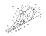
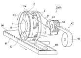
- FIG. 1 is a schematic perspective view showing one embodiment (first embodiment) of the fiber stacking apparatus of the present invention (first invention).
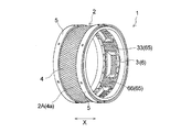
- FIG. 2 is a diagram in which the outer peripheral portion (recess for accumulation) of the rotary drum in the fiber stacking device shown in FIG. 1 is developed in a planar shape.
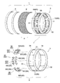
- FIG. 3 is an exploded perspective view of the outer peripheral portion of the rotating drum shown in FIG.
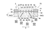
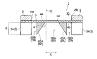
- FIG. 4 is a perspective view schematically showing a cross section taken along line II of FIG.
- FIG. 5 is a cross-sectional view schematically showing a part of a cross section taken along line II of FIG. 6 is a perspective view schematically showing a cross section taken along line II-II in FIG.
- FIG. 7 is a perspective view showing the piled product released from the collecting concave portion of the rotary drum in the pile device shown in FIG. 1.
- FIG. 8 is a perspective view of the outer peripheral portion (recess for accumulation) of the rotating drum in another embodiment (second embodiment) of the fiber stacking apparatus of the present invention (first invention).
- FIG. 9 is an exploded perspective view of the outer periphery of the rotating drum shown in FIG.
- FIG. 10 is a diagram schematically showing a cross section along a drum width direction (a direction parallel to the rotation axis of the rotary drum) of a part of the bottom of the accumulation concave portion in the outer peripheral portion of the rotary drum shown in FIG.
- FIG. 10 (a) is a perspective view of a region where the adjustment body is not disposed (high basis weight product fiber region), and FIG. 10 (b) is a region where the adjustment body is disposed (low basis weight product fiber region). It is a perspective view.
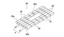
- FIG. 11 is a perspective view showing the piled article released from the accumulation recess of the rotating drum shown in FIG.
- FIGS. 12 (a) to 12 (e) are plan views schematically showing the correspondence between the first layer and the second layer in the adjustment body according to the present invention (first invention), respectively.
- FIG. 13 is a view corresponding to FIG. 4 of still another embodiment of the fiber stacking apparatus of the present invention (first invention).
- FIG. 14 (a) to 14 (d) are cross-sectional views schematically showing cross sections along the drum width direction of the opening of the adjusting body according to the present invention (first invention).
- FIG. 15 is a schematic perspective view showing still another embodiment of the fiber stacking device of the present invention (first invention) with a partial see-through.
- FIG. 16 is a schematic perspective view of one embodiment of the fiber stacking device of the present invention (second invention).
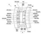
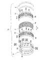
- FIG. 17 is a perspective view showing a rotary drum of the fiber stacking apparatus shown in FIG.
- FIG. 18 is a diagram illustrating the configuration of the rotating drum shown in FIG.
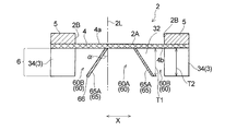
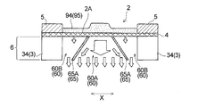
- FIG. 19 is a cross-sectional view showing a cross section (end surface) along the drum width direction (direction parallel to the rotation axis of the rotary drum) at a specific portion of the accumulation recess and the flow rate adjusting member of the rotary drum shown in FIG.
- This specific part is a part where the defining member extending in the drum circumferential direction, indicated by reference numeral 65A in FIG.
- FIG. 20 is a partially enlarged perspective view of a flow rate adjusting member constituting the rotating drum shown in FIG.
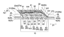
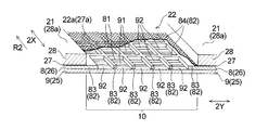
- FIG. 21 is a cross-sectional view (corresponding to FIG. 19) showing a state in which the molding material is piled in the accumulation concave portion of the rotating drum shown in FIG.
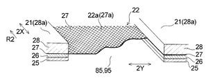
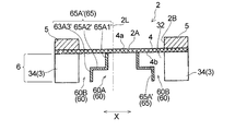
- FIG. 22A is a perspective view showing the piled product released from the accumulation recess shown in FIG. 21, and
- FIG. 22B is a cross-sectional view taken along the line II in FIG. 22A.
- FIG. 23 is a diagram (corresponding to the lower diagram of FIG.
- FIG. 24 is a diagram (corresponding to FIG. 19) for explaining a main part of still another embodiment of the rotary drum according to the present invention (second invention).
- FIG. 25 is a diagram (corresponding to FIG. 18) for explaining the main part of still another embodiment of the rotary drum according to the present invention (second invention).
- FIG. 26 is a cross-sectional view (corresponding to FIG. 19) showing a cross section along the drum width direction (direction parallel to the rotation axis of the rotary drum) of the accumulation recess of the rotary drum and the flow rate adjusting member shown in FIG.
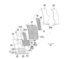
- FIG. 27 is a perspective view (corresponding to FIG.
- FIG. 28 is a diagram (corresponding to FIG. 19) for explaining the main part of still another embodiment of the rotating drum according to the present invention (second invention).
- FIG. 29 is a schematic perspective view illustrating another embodiment of the fiber stacking device of the present invention (second invention) with a partial see-through.
- the present invention (first invention) relates to a fiber stacking apparatus capable of adjusting the fiber stacking amount of a molded body material without causing uneven fiber stacking.
- the present invention (second invention) relates to a fiber stacking apparatus capable of accurately adjusting the basis weight of each part of the molded body.
- FIG. 1 shows an outline of a first embodiment of the fiber stacking apparatus of the present invention.
- the fiber stacking apparatus 100 according to the first embodiment is disposed at a rotary drum 2 that is rotationally driven in the direction of arrow R2, a duct 4 that supplies a molded body material to the outer peripheral surface 21 of the rotary drum 2, and an obliquely lower side of the rotary drum 2.
- a transfer roll 5 that is rotationally driven in the direction of arrow R5, a vacuum conveyor 6 disposed below the transfer roll 5, and a cutting device 7.
- a vacuum box 11 is further provided between the duct 4 and the transfer roll 5 in the circumferential direction of the rotary drum 2, and a mesh belt 13 is provided between the vacuum box 11 and the rotary drum 2.
- the windbreak plate 15 is provided close to the outer peripheral surface of the transfer roll 5 so as to pass between the transfer roll 5 and the rotary drum 2. Note that the vacuum box 11 and the windbreak plate 15 are means for stably transferring the piled articles in the accumulation recess 22 without losing the shape, and relatively, like the piled articles 32 shown in FIG. When a piled fiber having a shape that does not easily lose its shape is obtained, it is not particularly necessary to install it, or it is not necessary to use it even if it is installed.
- a piled article 32A shown in FIG. 11 has a concave portion (groove portion) 38 having a lattice shape in a plan view and a convex portion 39 formed in an eye portion of the lattice, and has a shape that is relatively easily deformed. It is delicate.
- the vacuum box 11 and the windbreak plate 15 are effective when a piled article having such a shape that is easy to lose its shape is obtained.
- the rotating drum 2 has a cylindrical shape and rotates around a horizontal axis in response to power from a motor such as a motor.
- the rotary drum 2 has an accumulation recess 22 on the outer peripheral surface 21 in which the molded body material is stacked.
- a plurality of the recesses 22 are formed at predetermined intervals in the circumferential direction (2X direction) of the rotary drum 2.
- the 2X direction is the circumferential direction of the rotating drum 2
- the 2Y direction is the width direction of the rotating drum 2 (a direction parallel to the rotation axis of the rotating drum 2).
- the rotary drum 2 includes a cylindrical drum body (not shown) made of a metal rigid body, a suction adjustment plate 25 that is fixed to the outer periphery of the drum body, and the suction drum.
- the space plate 26 fixed to be overlapped on the outer surface 25 a side of the adjustment plate 25, the porous plate 27 (porous member) fixed to be overlapped on the outer surface 26 a side of the space plate 26, and the outer surface of the porous plate 27 27a, and a pattern forming plate 28 fixed to be overlapped on the 27a side.
- the drum body and the plates 25 to 28 are fixed to each other by a known fixing means such as a bolt or an adhesive.
- each constituent member (suction adjustment plate 25, space plate 26, porous plate 27, pattern forming plate 28, etc.) of the rotary drum 2 is the fiber pile of the molded material in the constituent member.
- the surface is directed to the supply side of the molded body material when it is formed.
- the inner surface of each constituent member is a surface directed to the side opposite to the supply side of the molding material (the inner side of the rotating drum) when the molding material is stacked in the constituent member.
- a molded object material is an absorber raw material.
- the molded body material includes a fiber material.
- various materials conventionally used for absorbent articles of absorbent articles such as sanitary napkins, panty liners, and disposable diapers can be used without particular limitation.
- pulp fibers such as defibrated pulp, short fibers of cellulosic fibers such as rayon fibers and cotton fibers, and short fibers of synthetic fibers such as polyethylene are used. These fiber materials can be used alone or in combination of two or more.
- a fibrous water-absorbing polymer can be used alone or together with the fibrous material.
- a deodorant, an antibacterial agent, etc. can also be used with a fiber material etc. as needed.
- the pattern forming plate 28 has an outer surface 28a that forms the outer peripheral surface 21 of the rotating drum 2 and an inner surface 28b that faces the rotating shaft side of the rotating drum 2, and an accumulation recess is provided between the outer surface 28a and the inner surface 28b.
- 22 has a space portion having a shape corresponding to the three-dimensional shape in 22. Except for this space portion, the pattern forming plate 28 is non-breathable so as not to allow air to pass therethrough.
- “non-breathable” includes both “non-breathable that does not allow air to pass through” and “non-breathable that allows a very small amount of air to pass but does not substantially allow air to pass through”. It means sex.
- the pattern forming plate 28 for example, a plate formed by machining a metal or resin plate such as stainless steel or aluminum to form an opening (a space corresponding to a three-dimensional shape in the recess 22), or a mold It is possible to use a plate in which the opening is integrally formed using, or a punched or etched plate, or a laminate of these plates.
- the porous plate 27 transmits an air flow (vacuum air) generated by suction from the inside of the device (inward of the rotating drum 2) to the outside of the device (outside of the rotating drum 2) and rides on the air flow. It is a breathable plate that holds the molded body material that is carried without allowing it to permeate and allows only air to permeate.
- the porous plate 27 is formed with a plurality of (multiple) suction holes (pores) penetrating the plate 27 in the thickness direction with a uniform distribution over the entire plate 27, and the accumulation recess 22 is a rotating drum. While passing through the space maintained at a negative pressure in 2, the suction hole functions as an air flow permeation hole.
- a metal or resin mesh plate, or a metal or resin plate formed with a plurality of (many) pores by etching or punching can be used.
- the adjusting body 10 that rectifies the air flow is disposed so as to overlap a part of the inner surface 27b of the plate 27.
- the adjustment body 10 is configured by sequentially laminating the first layer 8 and the second layer 9 in the order closer to the porous plate 27.
- the adjustment body 10 includes a suction adjustment plate 25 and a space plate 26, and the bottom surface of the recess 22 in the space plate 26 in the plan view of the accumulation recess 22 as shown in FIG. Part of the portion overlapping 22 a is the first layer 8, and the portion of the suction adjustment plate 25 overlapping the first layer 8 is the second layer 9.
- the “plan view” refers to an object (such as a concave portion for accumulation) viewed from the outside in the normal direction of the outer peripheral surface 21 of the rotating drum 2 (direction perpendicular to the rotating shaft direction of the rotating drum 2). Means the case.
- the first layer 8 has a plurality of first openings 81 penetrating the first layer 8 in the thickness direction, and opening defining portions 82 for partitioning the first openings 81.
- the opening defining portion 82 includes a plurality of MD defining members 83 extending in the transport direction R2 (circumferential direction of the rotating drum 2, 2X direction) of the concave portion 22 for accumulation, and a direction (rotating drum 2) orthogonal to the transport direction. And a plurality of CD defining members 84 extending in the width direction and the 2Y direction).
- “extending in the conveying direction of the stacking concave portion” means that the MD defining member may extend substantially in the transporting direction.
- the definition member is not limited to a straight line parallel to the conveyance direction, and includes a case where the MD definition member is curved along the conveyance direction, and the MD definition member is not parallel to the conveyance direction. Includes a case where the angle formed with the transport direction is along a crossing direction of 45 ° or less.
- “extending in the direction (orthogonal direction) perpendicular to the conveying direction of the stacking recess” means that the CD defining member extends substantially in the orthogonal direction. 22 in a plan view, the CD defining member is not limited to a linear shape parallel to the orthogonal direction, and includes a case where the CD defining member is a curved shape along the orthogonal direction. This includes the case where the angle formed with the orthogonal direction is not parallel to the orthogonal direction but is along a crossing direction of 45 ° or less.
- the opening defining part 82 includes six MDs in a straight line in plan view parallel to the transport direction (2X direction) of the accumulation concave part 22. It is composed of a member 83 and five linear CD definition members 84 in plan view that are parallel to a direction (2Y direction) orthogonal to the conveying direction of the accumulation recess 22, and a total of ten straight lines in plan view. Are formed in a lattice shape in plan view.
- the first opening portion 81 is located at a portion of the lattice of the lattice-like opening portion defining portion 82 and has a quadrangular shape in plan view.
- the opening defining part 82 (defining members 83 and 84) has a non-breathable property that does not allow air to pass therethrough.
- the “non-breathable” here is as described above.
- a metal such as stainless steel, aluminum, iron, or a resin can be used as a material for forming the non-breathable opening defining portion 82 (defining members 83 and 84).
- a second opening 91 that penetrates the second layer 9 in the thickness direction is formed in a portion of the second layer 9 that overlaps the plurality of first openings 81 in a plan view of the concave portion 22 for accumulation as shown in FIG.
- the first openings 81 are formed so as to correspond to the first openings 81, and the openings 81 and 91 having the corresponding relationship overlap each other in the plan view.
- one second opening 91 of the second layer 9 corresponds to one first opening 81 of the first layer 8.
- the first opening 81 and the second opening 91 correspond one-to-one.
- the second opening 91 is separated from the CD defining member 84 in each of the plurality of first openings 81 in the plan view of the accumulation recess 22 as shown in FIG.
- the portion that overlaps with the CD defining member 84 in the second layer 9 (hereinafter also referred to as the CD defining member corresponding portion) and its vicinity have a non-breathable property that does not allow air to pass. Can be mentioned.
- the “non-breathable” here is as described above.
- Reference numeral 92 in FIG. 3 indicates the CD defining member corresponding portion of the second layer 9 and the vicinity thereof.
- the CD defining member corresponding portion and its vicinity 92 are formed of a non-breathable material such as a metal such as stainless steel, aluminum or iron, or a resin, and an opening (second portion). It does not have a through-hole penetrating the layer 9 in the thickness direction, and has air permeability.
- “in the vicinity of the CD defining member corresponding portion” refers to the 1 over the entire length of one CD defining member 84 in the 2Y direction (the width direction of the rotating drum 2) in the plan view of the accumulation recess 22. This is an area extending along the CD defining member 84, and has a certain width (length in the 2X direction) W1 (see FIG. 4). Further, the width (the length in the 2X direction) of the CD defining member corresponding portion is the same as the width W2 (see FIG. 4) of the corresponding CD defining member 84.
- the second layer 9 in the first embodiment has not only the CD defining member 84 but also the MD defining member 83 and a portion overlapping therewith and a non-breathable portion that does not allow air to pass therethrough. That is, in a plan view of the accumulation recess 22 as shown in FIG. 2, the second opening 91 is located at a position spaced apart from the MD defining member 83 inside each of the plurality of first openings 81 and the second layer 9.
- the portion that overlaps the MD defining member 83 hereinafter also referred to as the MD defining member corresponding portion
- the “non-breathable” here is as described above.
- the MD defining member corresponding portion and its vicinity 93 are formed of a non-breathable material such as stainless steel, aluminum, iron or the like, or resin, like the other portions of the suction adjusting plate 25, and the opening portion (second portion). It does not have a through-hole penetrating the layer 9 in the thickness direction, and has air permeability.
- the length of the MD defining member 83 in the 2X direction is 1 in the plan view of the accumulation recess 22.
- the region extends along the MD defining member 83 and has a certain width (length in the 2Y direction) W3 (see FIG. 4). Further, the width (the length in the 2Y direction) of the MD defining member corresponding portion is the same as the width W4 (see FIG. 4) of the corresponding MD defining member 83.
- the two MD defining members 83 and 83 that are opposed to each other are located at positions apart from each other. Accordingly, the second opening 91 existing inside one first opening 81 in a plan view of the recess 22 has a smaller opening area than the first opening 81.
- the “opening area” of the openings 81 and 91 is the opening at the opening end closest to the porous plate 27 in the opening (the first opening 81 and the second opening 91). It means an area (in the case where the opening and the porous plate are in contact with each other), the area of the contact area.
- the adjustment body 10 since the first opening 81 and the second opening 91 overlap each other in plan view of the accumulation recess 22, the adjustment body 10 (first It can be said that one opening is formed penetrating the layer 8 and the second layer 9) in the thickness direction. As described above, since the second opening 91 existing inside the first opening 81 in the plan view of the recess 22 has a smaller opening area than the first opening 81, both openings In consideration of such a magnitude relationship between 81 and 91, the adjustment body 10 in the first embodiment includes a plurality of openings that penetrate the adjustment body 10 in the thickness direction (first openings 81 that overlap each other in plan view of the recess 22.
- the opening area is smaller than the opening end portion closer to the aperture (the opening end portion of the first opening portion 81).
- the second opening 91 is formed at the center of each of the plurality of first openings 81 in the plan view of the concave portion 22 for accumulation.
- the first opening 81 and the second opening 91 existing therein have a similar shape in plan view.
- Both openings 81 and 91 have a quadrangular shape in plan view. That is, regarding the shape of the openings 81 and 91 in plan view, the second opening 91 has a similarity ratio of less than 1 with respect to the corresponding first opening 81.
- the adjustment body 10 (the first layer 8 and the second layer 9) having the above-described configuration is disposed on the inner surface 27b side of the porous plate 27 forming the bottom surface 22a of the accumulation recess 22, the recess 22 described later is provided.
- an air flow (vacuum) that sucks the molded body material generated by suction from the inside of the apparatus.
- the air volume when air flows through the porous plate 27 is suppressed. That is, as shown in FIG. 5, the air flow (indicated by an arrow in FIG.
- the porous plate 27 inherently has air permeability in the region where the adjusting body 10 is disposed. Since it is obstructed, the air volume of the air flow is suppressed.
- the basis weight of the molded body material depends on the amount of air flowing through the porous plate 27. Therefore, by arranging the adjusting body 10 in a region corresponding to a portion on the inner surface 27b side of the porous plate 27 where the basis weight of the molded body material to be stacked is smaller than other portions, a desired portion is obtained.
- a compact with a reduced basis weight can be produced with simple equipment. For example, when manufacturing an absorbent used for absorbent articles such as disposable diapers or sanitary napkins as a molded product, absorbent raw materials such as pulp and water-absorbing polymers are concentrated in parts where high absorption capacity is required. By using the adjusting body 10 to reduce the basis weight as much as possible, it is possible to obtain an absorbent body excellent in both absorption performance and reduction in discomfort and discomfort.
- the second surface that substantially functions as a suction portion for the molded body material on the bottom surface 22a.
- the air flow rate suction force of the molded material
- the first opening 81 having an opening area larger than that of the second opening 91 is provided on the wind flow of the air flow than the second opening 91, thereby
- a space of a predetermined capacity composed of the first opening 81 is formed between the porous plate 27 and the second opening 91, the air flow that has passed through the porous plate 27 flows into the second opening 91. By passing through this space before passing through, it is rectified. As a result, the variation in the air volume of the air flow in the porous plate 27 is reduced, and the occurrence of uneven stacking is effectively prevented.
- a plurality of spaces (spaces B to D) partitioned from each other are formed inside the rotary drum 2, and a part (space B) of the plurality of spaces is set to a negative pressure.
- the accumulation concave portion 22 is conveyed in the same direction by the rotation of the rotary drum 2 in the R2 direction, and passes through the space B maintained at a negative pressure. Airflow flows from the outside of the drum to the inside.
- the 2nd opening part 91 has overlapped with the CD definition member 84 in planar view of the recessed part 22, or the CD definition member corresponding
- the plurality of first openings 81 are transported in the conveying direction R2 of the recess 22 via the second opening 91 overlapping the CD defining member 84 or the air-permeable portion.
- the air flows are communicated with each other so as to be able to pass through in the circumferential direction of the rotating drum 2 and the 2X direction.
- the transport direction R2 The first opening 81 (front first opening 81) positioned relatively on the front side is affected by the air flow flowing through the front first opening 81 when the first opening 81 passes through the space.
- a turbulent flow is generated in the opening 81, whereby the rectifying effect by the first opening 81 described above is impaired, and there is a possibility that the occurrence of uneven fiber stacking cannot be prevented.
- the second opening 91 is separated from the CD defining member 84 inside each of the plurality of first openings 81 in the plan view of the accumulation recess 22.
- the portion corresponding to the CD defining member of the second layer 9 and its vicinity 92 are non-breathable portions that do not allow air to pass therethrough, and the plurality of first openings 81 have air in the transport direction R2 of the recesses 22.
- the flows are not in communication with each other so that they can pass through. Therefore, turbulent flow does not occur in the rear side first opening 81 before passing through the space maintained at the negative pressure of the rotary drum 2, and the rectifying effect by the first opening 81 described above. Is definitely played.
- the second opening 91 is located not only from the CD defining member 84 but also from the MD defining member 83 extending in the direction orthogonal thereto, and
- the portion of the second layer 9 that overlaps the opening defining portion 82 and the vicinity thereof (92, 93) are non-breathable portions.
- the plurality of first openings 81 are not in communication with each other so that an air flow can pass in both the transport direction R2 of the accumulation recess 22 and the direction orthogonal thereto, and a space formed by each first opening 81. Therefore, the rectifying effect by the first opening 81 described above is more reliably exhibited.
- the second opening 91 is formed in the center of each of the plurality of first openings 81 in the plan view of the accumulation recess 22, and further, the recess 22.
- the first opening 81 and the second opening 91 existing in the first opening 81 are similar to each other in plan view. These configurations are effective for stable expression of the rectifying effect by the first opening 81 described above.
- the width W1 in the vicinity of the CD defining member corresponding portion of the second layer 9 (the portion overlapping the CD defining member 84 in plan view of the concave portion 22 for accumulation) is preferably 1 mm or more, more preferably It is 2 mm or more, preferably 10 mm or less, more preferably 5 mm or less, more specifically preferably 10 to 1 mm, and further preferably 5 to 2 mm.
- the width W2 (see FIG.
- the width W3 in the vicinity of the MD defining member corresponding portion of the second layer 9 (the portion overlapping the MD defining member 83 in the plan view of the accumulation recess 22) is preferably 1 mm or more, more preferably 2 mm. Above, and preferably 10 mm or less, more preferably 5 mm or less, more specifically, preferably 10 to 1 mm, more preferably 5 to 2 mm.
- the width W4 (see FIG.
- the MD defining member 83 of the first layer 8 is preferably 0.5 mm or more, more preferably 1 mm or more, and preferably 5 mm or less, more preferably 2 mm or less, more specifically. Is preferably 5 to 0.5 mm, more preferably 2 to 1 mm.
- the length W5 (see FIG. 2) of the first opening 81 in the 2X direction is preferably 5 mm or more, more preferably 10 mm or more, and preferably 30 mm or less, more preferably 25 mm or less, more specifically, preferably Is 5 to 30 mm, more preferably 10 to 25 mm.
- the length W6 of the first opening 81 in the 2Y direction is preferably 5 mm or more, more preferably 10 mm or more, and preferably 20 mm or less, more preferably 15 mm or less, more specifically preferably Is 5 to 20 mm, more preferably 10 to 15 mm.
- the length W7 of the second opening 91 in the 2X direction is preferably 5 mm or more, more preferably 10 mm or more, and preferably 30 mm or less, more preferably 25 mm or less, more specifically, preferably Is 5 to 30 mm, more preferably 10 to 25 mm.
- the length W7 of the second opening 91 in the 2X direction is preferably 5 mm or more, more
- the length W8 (see FIG. 2) of the second opening 91 in the 2Y direction is preferably 2 mm or more, more preferably 5 mm or more, and preferably 20 mm or less, more preferably 15 mm or less, more specifically preferably Is 20 to 2 mm, more preferably 15 to 5 mm.
- the ratio (S2 / S1) of the opening area S2 of the second opening 91 to the opening area S1 of the first opening 81 is preferably 50 to 5%, more preferably 15 to 7%.
- the thickness T (see FIG. 5) of the opening defining portion 82 (MD defining member 83, CD defining member 84) of the first layer 8 is preferably 2 mm or more, more preferably 3 mm or more, and preferably 10 mm. Hereinafter, it is more preferably 5 mm or less, more specifically preferably 10 to 2 mm, and further preferably 5 to 3 mm.
- the adjusting body 10 (the first layer 8 and the second layer 9) is not arranged corresponding to the entire area of the porous plate 27, and as shown in FIG.
- the plate On the inner surface 27 b side of the plate 27, the plate is disposed only in the region corresponding to the rear side in the transport direction R ⁇ b> 2 of the accumulation recess 22, and is not disposed in other regions including the front side.
- the accumulation concave portion 22 includes an adjustment body arrangement region 24 in which the adjustment body 10 is disposed on the inner surface 27b side of the porous plate 27 that forms the bottom surface 22a of the concave portion 22, and an inner surface 27b side of the porous plate 27.
- an adjustment body non-arrangement region 23 in which the adjustment body 10 is not arranged.
- the space plate 26 penetrates the space plate 26 in the thickness direction in the portion other than the first layer 8, and the first opening portion.
- a first large opening 85 having a rectangular shape in plan view having a larger opening area than 81 is formed, and the suction adjustment plate 25 has a rectangular shape in plan view that penetrates the suction adjustment plate 25 in the thickness direction.
- Two large openings 95 are formed corresponding to the first large openings 85.
- the openings 85 and 95 have a congruent relationship in plan view, and the second large opening 95 has a similarity ratio of 1 to the first large opening 85.
- the openings 85 and 95 have a size that overlaps with the entire area of the adjustment body non-arrangement region 23 of the recess 22 in plan view of the accumulation recess 22. As shown in FIG. 6, the substantially entire region on the inner surface 27 b side of the porous plate 27 is both openings 85 and 95. Therefore, in the adjustment body non-arrangement region 23 of the recess 22, the air permeability inherent to the porous plate 27 is not hindered, and the amount of air flow (vacuum air) generated by suction from the inside of the apparatus and sucking the molded body material is Therefore, compared with the adjustment body arrangement
- the concave portion 22 for accumulation in the first embodiment has an adjustment body non-arrangement region (high basis weight pile fiber region) 23 for stacking the molded body material at a relatively high basis weight and the molded body material relative to each other.
- region) 24 which piles up to low basic weight is provided in the conveyance direction R2 (longitudinal direction) of this recessed part 22 (refer FIG. 2).
- the adjustment body non-arrangement region (high basis weight pile fiber region) 23 is not provided with the adjustment body 10 on the inner surface 27b side of the porous plate 27 that forms the bottom surface 22a of the concave portion 22 for accumulation.
- the adjustment body 10 is arranged on the inner surface 27 b side of the porous plate 27 in the low basis weight pile fiber region) 24.
- the inner side (rotary shaft side) of the rotary drum 2 is partitioned from each other in the circumferential direction (2X direction) of the rotary drum 2.
- Spaces B, C, and D are formed.
- a known exhaust device such as an intake fan is connected to the space B, and the space B can be maintained at a negative pressure by operating the exhaust device.
- External air flows into the space C by suction from the vacuum box 11 side, which will be described later, and external air flows into the space D by suction from the transfer roll 5 side.
- the space C is separated from the space D, which is a region after the transfer, in order to satisfactorily perform the transfer on the space C (transfer of the piled material in the recess 22 to the transfer roll 5 or the like).
- the rotary drum 2 is placed in a space (space C) corresponding to the transfer position of the piled material in the concave portion 22 to the transfer roll 5 from the inside of the rotary drum 2 to the bottom surface 22a (porous plate 27) of the concave portion 22.
- the rotating drum 2 has one end in the axial direction of the rotating shaft sealed with a plate that rotates integrally with the rotating drum 2, and the other end sealed airtight with a plate that does not rotate.
- the spaces B to D are partitioned by a plate provided from the rotating shaft side of the rotating drum 2 toward the inner surface of the rotating drum 2.
- the space C is normally set to a negative pressure or zero pressure (atmospheric pressure) that is weaker than the space B. From the viewpoint of transportability of the piled material, the space C is made a weak negative pressure and the piled material is sucked into the recessed portion 22 until the piled material in the accumulation recess 22 is transferred onto the transfer roll 5. However, if there is no particular problem in transportability, the space C is preferably zero pressure in consideration of transferability. Further, since the space D is a region through which the concave portion 22 passes after the piled material in the concave portion 22 is transferred onto the transfer roll 5, a zero pressure or a positive pressure is preferable.
- one end side of the duct 4 covers the outer peripheral surface of the rotating drum 2 positioned on the space B, and a molded material material introducing device is provided on the other end side (not shown).
- the molded body material introducing device includes, for example, a pulverizer that pulverizes sheet-like wood pulp into defibrated pulp and feeds the defibrated pulp (fiber material) into the duct 4.
- a water-absorbing polymer introduction part for introducing water-absorbing polymer particles in the middle of the duct 4 can also be provided.
- the transfer roll 5 has a cylindrical outer peripheral portion having air permeability, and the outer peripheral portion rotates around a horizontal axis upon receiving power from a prime mover such as a motor.
- a prime mover such as a motor.
- a known exhaust device such as an intake fan is connected to the space E, and the interior of the space E can be maintained at a negative pressure by operating the exhaust device.
- a plurality of (many) suction holes are formed on the outer peripheral surface of the transfer roll 5 to communicate the inside and outside. While these suction holes pass over the space E maintained at a negative pressure, air is sucked into the inside from the outside, and the piled material in the recess 22 is drawn from above the rotary drum 2 by the suction force. It moves smoothly onto the transfer roll 5.
- the vacuum conveyor 6 includes an endless breathable belt 63 laid across a drive roll 61 and driven rolls 62, 62, and a vacuum box 64 disposed at a position facing the transfer roll 5 with the breathable belt 63 interposed therebetween. It has.
- the vacuum box 11 has a box-like shape having upper and lower surfaces, left and right side surfaces, and a rear surface, and has an opening that opens toward the rotating drum 2.
- the vacuum box 11 is connected to a known exhaust device (not shown) such as an intake fan via an exhaust pipe (not shown), and the inside of the vacuum box 11 can be maintained at a negative pressure by the operation of the exhaust device. It is.
- the mesh belt 13 is a belt-like breathable belt having a mesh connected endlessly, and is continuously guided along a plurality of free rolls 14 and transfer rolls 5 to move along a predetermined path. The mesh belt 13 is driven by the rotation of the transfer roll 5. As shown in FIG.
- the mesh belt 13 is introduced on the outer peripheral surface of the rotating drum 2 in the vicinity of the downstream end portion 41 of the duct 4 and then between the vacuum box 11 and the rotating drum 2 and the transfer roll. 5 and the rotating drum 2 are arranged so as to pass sequentially. While the mesh belt 13 passes in front of the opening of the vacuum box 11, the mesh belt 13 is in contact with the outer peripheral surface of the rotating drum 2, and the rotating drum is in the vicinity of the closest portion between the transfer roll 5 and the rotating drum 2. 2 moves away from the outer peripheral surface of 2 and onto the transfer roll 5.
- the mesh belt 13 has small pores as compared to the suction holes of the transfer roll 5, and suction from the pores of the mesh belt 13 that overlaps with the suction holes with suction from the suction holes of the transfer roll 5.
- a pair of windbreak plates 15 are provided on both sides of the area where the suction holes are formed in the width direction of the outer peripheral surface of the transfer roll 5 to prevent or reduce the inflow of wind from the side, This prevents the piled article released from the concave portion 22 from being deformed.
- the material of the windbreak plate 15 is not particularly limited, but is preferably made of metal or synthetic resin and has a thickness of about 0.5 to 10 mm from the viewpoint of providing rigidity that can resist wind.
- the cutting device 7 for example, in the manufacture of absorbent articles such as sanitary napkins and diapers, those conventionally used for cutting absorbent continuous bodies can be used without particular limitation.
- the cutting device 7 shown in FIG. 1 includes a cutter roll 72 having a cutting blade 71 on the peripheral surface and an anvil roll 73 having a smooth peripheral surface for receiving the cutting blade.
- the manufacturing method according to the present embodiment includes a fiber stacking step in which the absorbent body material (molded body material) supplied in an air stream is sucked into the stacking concave portion 2 of the rotary drum 2 in the fiber stacking apparatus 100 and stacked. To do.
- the exhaust device connected to each of the space B in the rotary drum 2, the space E in the transfer roll 5, and the vacuum box 11 is operated to make negative pressure.
- an air flow vacuum air
- the rotary drum 2 and the transfer roll 5 are rotated, and the vacuum conveyor 6 is operated.
- the molded body material introduction device is operated to supply the absorbent body material into the duct 4, the absorbent body material rides on the air flow flowing through the duct 4 and becomes scattered, and the outer periphery of the rotary drum 2. Supplied towards the surface 21.
- the absorbent material While the portion covered with the duct 4 is being conveyed, the absorbent material is sucked into the accumulation recess 22 of the rotary drum 2 and piled up.
- the individual recesses 22 of the rotary drum 2 are sucked from the bottom surface 22a while passing over the space B maintained at a negative pressure.
- the absorber raw material introduced from the molding material introduction device or the water-absorbing polymer introduction portion into the duct 4 by suction from the suction hole of the porous plate 27 forming the bottom surface 22a. An air flow to be transported is generated, and the absorbent material transported on the air flow is piled in the recess 22.
- the amount of accumulated absorbent material is set to be different.
- the high basis weight stacking region) 23 is relatively high in the basis weight
- the adjustment body arrangement region (low basis weight stacking region) 24 is stacked in the relatively low basis weight (see FIG. 2).
- the surface of the fiber pile in the concave portion 22 absorbs at the boundary between the adjustment body non-arrangement region 23 and the adjustment body arrangement region 24.
- a level difference due to the difference in the amount of fiber of the body material is formed, and the surface of the adjustment body arrangement region 24 is located at a relatively low position with respect to the surface of the adjustment body non-arrangement region 23.
- the rotary drum 2 is further rotated.
- the pile 32 in the recess 22 comes to a position opposite to the vacuum box 11, it is sucked to the mesh belt 13 by suction from the vacuum box 11, and in this state, rotates with the transfer roll 5. It is transported to the closest part to the drum 2 or the vicinity thereof.
- the pile 32 in the state of being sucked onto the mesh belt 13 is released from the recess 22 by suction from the transfer roll 5 side and transferred onto the transfer roll 5 together with the mesh belt 13.
- FIG. 7 shows the fiber pile 32 immediately after being released from the accumulation recess 22 of the first embodiment.
- the piled product 32 has a portion corresponding to the adjustment body non-arranged region (high basis weight piled region) 23 of the recess 22, which has a relatively large amount of piled absorbent material.
- the portion corresponding to the adjustment part arrangement region (low basis weight product fiber region) 24 of the weight part (thick part) 33 and the recess 22 is a low basis weight part (thin part) where the amount of fiber of the absorbent material is relatively small. ) 34.
- one surface 32b (contact surface with the bottom surface 22a of the concave portion 22) of the piled article 32 is substantially flat, while the other surface 32a (opposite to the contact surface with the bottom surface 22a of the concave portion 22).
- the side surface has a step at the boundary between the high basis weight portion 33 and the low basis weight portion 34 and is not flat.
- the piled product 32 transferred onto the transfer roll 5 is conveyed while receiving suction from the transfer roll 5 side, and is introduced onto a vacuum conveyor 6 disposed below the transfer roll 5. It is delivered onto a core wrap sheet 37 made of a conductive nonwoven fabric or the like. Thereafter, as shown in FIG. 1, both side portions along the conveying direction of the core wrap sheet 37 are folded back, and the upper and lower surfaces of the piled article 32 are covered with the core wrap sheet 37. Then, the piled article 32 covered with the core wrap sheet 37 is cut into a predetermined size by the cutter roll 72 of the cutting device 7 together with the core wrap sheet 37. Thus, the absorbent body 3 covered with the core wrap sheet 37 is obtained.
- the absorbent body 3 includes a high basis weight portion 33 having a relatively high basis weight stacked in the adjustment body non-arrangement region (high basis weight product fiber region) 23 of the recess 22 and an adjustment body arrangement region (low basis weight product fiber). Region) 24 and a low basis weight portion 34 having a relatively low basis weight, and the absorbent material is partially different in the amount of fiber. Due to the action of the adjusting body 10 described above, the absorbent body 3 (particularly, the low basis weight portion 34) does not show uneven accumulation, and the absorbent body 3 can be used for absorbent articles such as disposable diapers, sanitary napkins, and incontinence pads. It has a high quality suitable as an absorber to be used.
- the absorbent body used in the disposable diaper is incorporated in the absorbent article so that the high basis weight portion 33 of the absorbent body 3 is the ventral side (front side) and the low basis weight portion 34 is the back side (rear side). It is preferable that the performance of the absorber 3 is maximized.
- forming a high basis weight part and a low basis weight part having different basis weights (amount of raw material accumulated) in the absorbent body has advantages such as obtaining an absorbent body that is flexible and improved in wearing feeling. .
- an absorbent body in which a low basis weight part is formed before and after or around a high basis weight part is flexible and excellent in wearing feeling.
- FIG. 8 shows an essential part of the second embodiment of the fiber stacking apparatus of the present invention
- FIG. 9 shows an exploded perspective view of the essential part.
- the recess 22A is partitioned into a plurality of regions in a direction parallel to the bottom surface 22a on at least a part of the outer surface 27a of the porous plate 27 forming the bottom surface 22a of the accumulation recess 22A.
- the concave partition member 35 is arranged in an overlapping manner.
- the space plate 26A has a narrow portion 29 having a relatively short length (width) in the 2Y direction (the width direction of the rotating drum 2) and a relatively long wide portion in the 2X direction (the rotating drum 2).
- the wide portion is the first layer 8 constituting the adjustment body 10.
- the narrow portion 29 is formed in a lattice pattern with the same opening pattern as the first layer 8 (the wide portion), and includes a plurality of (a large number of) openings 81A having the same shape and the same size as the first openings 81 of the first layer 8.
- the narrow portion 29 has a rectangular shape in plan view and is located at the center in the 2Y direction of the space plate 26A. The narrow portion 29 entirely overlaps the second large opening 95 of the suction adjustment plate 25 in the plan view of the accumulation recess 22A.
- the recess partitioning member 35 has a plurality of openings 36 that penetrate the recess partitioning member 35 in the thickness direction, and opening defining portions 37 that partition each opening 36.
- the opening defining portion 37 is formed in a lattice shape in plan view, and each opening portion 36 is located at the grid portion of the lattice-shaped opening defining portion 37 and is viewed in plan view. It has a square shape.
- the opening defining portion 37 has a non-breathability that prevents air from passing therethrough.
- the “non-breathable” here is as described above.
- a material for forming the non-breathable opening defining portion 37 a metal such as stainless steel, aluminum, iron or the like, a resin, or a combination thereof can be used.
- the opening defining portion 37 has a rectangular shape in plan view, and is arranged at the center in the 2Y direction of the bottom surface 22a of the concave portion 22A for accumulation, with its longitudinal direction coinciding with the 2X direction.
- the overall length of the recess partition member 35 in the 2X direction is shorter than that of the space plate 26A, and the length (width) of the recess partition member 35 in the 2Y direction is the same as that of the narrow portion 29 of the space plate 26A.
- the recess partitioning member 35 has the same opening pattern as the space plate 26A [the narrow portion 29, the first layer (the wide portion)], and the opening 36 has the same shape as the openings 81 and 81A of the space plate 26A. It is the same size.
- the recess partition member 35 is fixed on the outer surface 27a of the porous plate 27 by a known fixing means such as a bolt or an adhesive so as to completely coincide with the narrow portion 29 in a plan view of the accumulation recess 22A. Yes.
- the adjustment body 10 is not disposed, and a part (2Y) of the adjustment body non-arrangement region (high basis weight accumulation fiber region) 23 for stacking the molded body material at a relatively high basis weight.
- a part (2Y) of the adjustment body non-arrangement region (high basis weight accumulation fiber region) 23 for stacking the molded body material at a relatively high basis weight At the center of the direction), as shown in FIG. 10 (a), one opening 36 of the recess partition member 35 and one opening 81A of the narrow portion 29 of the space plate 26A are in a one-to-one relationship. It corresponds with.
- region) 24 which arrange
- Each of the two openings 91 has a one-to-one correspondence.
- the adjustment body arrangement region 24 includes the opening 36 of the recess partition member 35 and the opening that penetrates the adjustment body 10 in the thickness direction (both openings 81 and 91 that overlap each other) in the plan view of the recess 22. The opening).
- the fiber stacking apparatus of the second embodiment provided with the rotating drum having the accumulation recess 22A having such a configuration can be used in the same manner as the fiber stacking apparatus of the first embodiment described above, and according to the manufacturing method described above.
- the absorber can be manufactured continuously. While the recess 22A passes over the space B (see FIG. 1) maintained at the negative pressure of the space drum 2, the bottom surface 22a of the recess 22A has a portion corresponding to the opening 36 of the recess partition member 35. While suction is normally performed from the bottom surface 22a, an opening portion is defined at a portion corresponding to the opening portion defining portion 37 of the concave section member 35 (a contact portion with the opening portion defining portion 37 of the bottom surface 22a).
- the absorbent material is stacked not only on the opening 36 but also on the opening defining part 37.
- the absorbent material is spread only in the opening 36 on the upstream side of the duct 4, and when the height of the loaded absorbent material reaches the thickness of the opening defining portion 37 (recessed partition member 35), In accordance with the entanglement between the absorbent raw materials and the flow of air in the duct 4 that conveys the absorbent raw materials, the absorbent raw material begins to pile on the opening defining portion 37 as well.
- the opening defining portion 37 is completely covered with the absorbent material.
- FIG. 11 shows the piled article 32A immediately after being released from the accumulation recess 22A in the manufacturing method described above.
- the piled article 32 ⁇ / b> A has a portion corresponding to the adjustment body non-arrangement region (high basis weight pile fiber region) 23 of the recess 22 ⁇ / b> A, and the amount of pile of the absorbent material is relatively high.
- the portion corresponding to the adjustment portion arrangement region (low basis weight product fiber region) 24 of the mass portion (thick portion) 33 and the recess 22A is a low basis weight portion (thin portion) with a relatively small amount of absorbent material. ) 34.
- one surface 32Ab contact surface with the bottom surface 22a of the recess 22A of the piled article 32A, as shown in FIG. 11, corresponding to the lattice-shaped opening defining portion 37 of the recess partition member 35.
- a plurality of continuous straight groove portions (recess portions) 38 extending in both the 2X direction and the 2Y direction are arranged in a lattice shape, and the plurality of openings 36 of the recess partition member 35 are formed in the lattice portion.
- convex portions 39 having a quadrangular shape in plan view are arranged, and one surface 32Ab has uneven portions having large undulations.
- the region where the concave and convex portion including the groove portion 38 and the convex portion 39 is not formed (the region around the concave and convex portion) and the top portion of the convex portion 39 are substantially flush with each other.
- the other surface 32Aa (the surface opposite to the contact surface with the bottom surface 22a of the recess 22A) of the piled fabric 32 has a high basis weight in the same manner as the other surface 32a of the piled fabric 32 shown in FIG. There is a step at the boundary between the portion 33 and the low basis weight portion 34, and it is not flat.
- the piled fiber 32A has a thick portion (high basis weight portion) 33 and a thin portion (low basis weight portion) 34 formed due to the presence or absence of the arrangement of the adjusting body 10, and the On one surface 32Ab of each of the thick portion 33 and the thin portion 34 (contact surface with the bottom surface 22a of the concave portion 22A), the convex portion 39 (high basis weight portion) and the groove portion 38 corresponding to the opening pattern of the concave portion partitioning member 35. It has an uneven part consisting of (low basis weight part).
- the stacked fabric 32 ⁇ / b> A absorbs disposable diapers, sanitary napkins, incontinence pads, and the like. It can be suitably used as an absorbent for use in articles.
- FIG. 91 corresponds, and the first opening 81 and the second opening 91 correspond one-to-one.
- a plurality of second openings 91 of the second layer 9 may correspond. 12 (a) to 12 (c), a plurality of second openings 91 having a circular shape in plan view correspond to one first opening portion 81 having a rectangular shape in plan view.
- a plurality of second openings 91 having a rectangular shape in plan view correspond to one rectangular opening having a rectangular shape in plan view.
- the first opening 81 and the second opening 91 corresponding to the first opening 81 are not in a similar relationship in plan view.
- the hatched part is a non-breathable part that does not allow air to pass through.
- the porous plate 27 is not shown for easy explanation.
- the first opening 81 is maintained at the negative pressure of the rotating drum 2.
- the air flow flows through the plurality of second openings 91 in the first opening 81 substantially simultaneously, so that the rectifying effect by the first opening 81 is more reliably ensured.
- the plurality of second openings 91 take into account the transport direction of the accumulation recess 22 (the direction parallel to the 2X direction). As shown in FIG. 4, it is preferable to arrange them in a line in a direction (2Y direction) orthogonal to the conveying direction of the recesses 22.
- the present invention (first invention) is not limited to the above-described embodiment and can be modified as appropriate.
- the second opening 91 is located away from both the CD defining member 84 and the MD defining member 83 and both defining members of the second layer 9 are used.
- 83 and 84 and the vicinity thereof are non-breathable parts, but in the present invention, at least the second opening 91 is at a position separated from the CD defining member 84,
- the portion of the second layer 9 that overlaps with the CD defining member 84 and the vicinity thereof may be a non-breathable portion. Therefore, as shown in FIG.
- the second opening 91 may be continuous so as to straddle the plurality of first openings 81 in the 2Y direction.
- each of the plurality of second openings 91 is continuous over substantially the entire length of the recess 22 in the 2Y direction. Therefore, the plurality of first openings 81 are in the 2Y direction. Via the continuous 2nd opening part 91, it is mutually connected so that an air flow can pass in 2Y direction.
- the adjusting body according to the present invention has a plurality of openings that penetrate the adjusting body in the thickness direction, and the opening is relatively close to the opening end that is relatively far from the porous member.
- the configuration is not limited to the above embodiment.
- the first layer 8 and the second layer 9 constituting the adjustment body 10 are separate bodies (see FIG. 5), but both layers 8 and 9 are integrally formed (the adjustment body 10 is It may be formed from a single-layer plate (see FIG. 14A).
- the cross-sectional view shape (the cross-sectional shape in the direction parallel to the rotation axis of the rotary drum 2) of the plurality of openings penetrating the adjustment body 10 in the thickness direction is shown in FIG. ),
- Vertical wall portions 71 (part of the first layer 8) and 72 parallel to the normal direction of the outer peripheral surface 21 of the rotary drum 2 (the thickness direction of the adjusting body 10; the vertical direction in FIG. 14).
- Part of the second layer 9) and the horizontal wall portion 73 (MD definition of the second layer 9) parallel to the normal direction (thickness direction of the adjusting body 10) and the direction (left-right direction in FIG. 14) perpendicular to the normal direction.
- the sectional view shape of the opening according to the present invention is not limited to that shown in FIG. 14 (a), and for example, as shown in FIG. 14 (b), it is a shape partially including a curved wall portion.
- FIG. 14C only the slanted wall portion extending in a direction intersecting the normal direction (thickness direction of the adjusting body 10) (excluding the direction orthogonal to the normal direction). It may be a shape made up of, or as shown in FIG.
- 14 (a) to 14 (d) may be integrally formed (formed from one layer of plate) as shown in the drawing, or may be used in the first and second embodiments. Thus, it may be composed of a plurality of layers that are separate bodies. 14 (a) to 14 (d), the opening end relatively closer to the porous member (porous plate 27) corresponds to the first opening 81 described above, and the relative The far opening end corresponds to the second opening 91 described above. Accordingly, the adjustment body 10 is an integrally molded embodiment (an embodiment formed from a single-layer plate), and the adjustment body 10 has the cross-sectional shape shown in FIGS. 14 (a) to 14 (d).
- the first opening 81 and the second opening 91 are provided as opening ends on one end side and the other end side in the thickness direction, and the description of the arrangement or size of the first opening portion 81 and the second opening portion 91 described above is as follows. Such a configuration in which the adjusting body 10 is integrally formed is also applicable.
- the adjusting body 10 is composed of two layers, the first layer 8 and the second layer 9, but is composed of a plurality of layers such as having a third layer and a fourth layer. May be.
- the accumulation recess 22 is intermittently formed in the outer circumferential surface 21 of the rotary drum 2 in the circumferential direction, but is continuously formed over the entire length in the circumferential direction. May be.
- the concave partition member 35 is disposed so as to overlap only a part of the outer surface 27a of the porous plate 27, but may be disposed so as to overlap the entire surface of the outer surface 27a. All the parts of only one embodiment described above can be used as appropriate.
- the porous plate 27 forming the bottom surface 22 a of the accumulation recess 22 is flat, but the depth of the recess 22 is reduced between the adjustment body non-arrangement area 23 and the adjustment body arrangement area 24.
- a step may be provided on the bottom surface 22a so that the height is different.
- a step is provided on the bottom surface 22a so that the bottom surface 22a of the adjustment body non-arrangement region 23 is lower than the bottom surface 22a of the adjustment body arrangement region 24, and the recess in the adjustment body non-arrangement region 23 is formed by such a step.
- the depth 22 is formed deeper than that of the adjusting body arrangement region 24.
- the recess partition member 35 is straddled across the step (so that the two regions 23 and 24 having different depths of the recess 22 are straddled).
- the concave section partition member 35 is deformed into a shape along the bottom surface of the concave section 22 for accumulation, or the adjustment body non-arrangement region in the concave section partition member 35 where the bottom surface 22a is at a relatively low position. It is preferable to increase the thickness at 23.
- the fiber stacking apparatus of the present invention is not limited to the fiber stacking apparatus 100 shown in FIG. 1, and may be configured as a fiber stacking apparatus 100A shown in FIG.
- a part of the side surface on the one end side in the axial length direction of the rotating drum 2 (a circular plate in plan view that defines the spaces B, C, and D in the rotating drum 2). Is shown in a transparent state.
- the fiber stacking apparatus 100 shown in FIG. 1 includes the vacuum box 11 and the windbreak plate 15 as means for stably transferring the fiber pile 32 in the accumulation recess 22 without losing its shape. As shown in FIG. 15, the fiber stacking apparatus 100A does not include such means.
- reference numeral 42 indicates a molded body material introducing device that can also be applied to the fiber stacking apparatus 100, and the molded body material introducing device 42 pulverizes a sheet-like wood pulp 45 by a pulverizer 43 and defibrated pulp.
- the defibrated pulp (fiber material) is fed into the duct 4.
- a water-absorbing polymer introduction portion 44 for introducing water-absorbing polymer particles is provided.
- a space B, a space C, and a part of the space D (a region located in the space D on the upstream side in the rotation direction R2 of the rotary drum 2 from the transfer position of the fiber pile 32).
- Is set to a negative pressure and the pile 32 formed in the accumulation recess 22 in the space B (in the duct 4) remains sucked into the recess 22, and the rotary drum 2 Is transferred to a predetermined transfer position (a position where the rotary drum 2 and the vacuum conveyor 6 are opposed to each other in the space D. The lowest point of the rotary drum 2), and is sucked from the conveyor 6 at the transfer position.
- the mold is released from the recess 22 and transferred onto the core wrap sheet 37 introduced onto the conveyor 6.
- release of the pile 32 from the recess 22 can be promoted.
- Such a so-called transfer blow promotes the release of the piled product from the accumulation recess when a piled product having a shape that is relatively difficult to lose its shape, such as the piled product 32 shown in FIG. 7, is obtained. It is particularly effective on the above.
- the absorbent body produced in the present invention (first invention) is preferably used as an absorbent body for absorbent articles.
- the absorbent article is mainly used to absorb and retain body fluids excreted from the body such as urine and menstrual blood.
- Absorbent articles include, for example, disposable diapers, sanitary napkins, incontinence pads, panty liners, etc., but are not limited to these, and widely include articles used to absorb liquid discharged from the human body. To do.
- the absorbent article typically includes a top sheet, a back sheet, and a liquid-retaining absorbent disposed between the sheets.
- the upper and lower surfaces of the absorber may be covered with one or a plurality of core wrap sheets.
- the back sheet may or may not have water vapor permeability.
- the absorbent article may further include various members according to specific uses of the absorbent article. Such members are known to those skilled in the art. For example, when the absorbent article is applied to a disposable diaper or a sanitary napkin, a pair or two or more pairs of three-dimensional guards can be arranged on the outer side of both sides of the absorbent body.
- a molding body material that is carried on an air flow generated by suction from the inside while having a concave portion for accumulation in which the molding body material is stacked on the outer surface, and conveying the concave portion for accumulation in one direction
- a fiber stacking device for stacking on the bottom surface of the concave portion for accumulation formed by a porous member having a plurality of suction holes
- On the inner surface side of the porous member an adjustment body for adjusting the air flow is disposed so as to overlap at least a part of the inner surface of the porous member,
- the adjustment body has a plurality of openings that penetrate the adjustment body in the thickness direction, and the opening is an opening end that is relatively close to an opening end that is relatively far from the porous member.
- a fiber stacking device with a smaller opening area than the part.
- the adjustment body is configured by sequentially laminating a first layer and a second layer in the order closer to the porous member,
- the first layer has a plurality of first openings penetrating the first layer in the thickness direction, and an opening defining portion for defining each first opening, and the opening defining portion is And an MD defining member extending in the transport direction of the concave portion for accumulation and a CD defining member extending in a direction perpendicular to the transport direction,
- a second opening that penetrates the second layer in the thickness direction is formed in a portion of the second layer that overlaps the plurality of first openings in a plan view of the accumulation recess.
- Each of the plurality of openings is composed of the first opening and the second opening that overlap each other in plan view, In the plan view of the concave portion for accumulation, the second opening is located at a position spaced apart from the CD defining member in each of the plurality of first openings, and the CD defining member in the second layer.
- the adjusting body is formed of a single layer plate, the first opening being the opening end portion relatively closer to the porous member, and the first opening portion being relatively far from the porous member.
- the ratio (S2 / S1) of the opening area (S2) of the second opening to the opening area (S1) of the first opening is preferably 50 to 5%, more preferably 15 to 7%.
- the second opening is in a position spaced apart from the MD defining member inside each of the plurality of first openings, and the MD defining member in the second layer
- the stacking apparatus according to any one of ⁇ 2> to ⁇ 4>, wherein the overlapping portion and the vicinity thereof have a non-breathable property that does not allow air to pass therethrough.
- ⁇ 6> The fiber stacking apparatus according to any one of ⁇ 2> to ⁇ 5>, wherein the second opening is formed at a center of each of the plurality of first openings in a plan view of the accumulation recess.
- any one of the above ⁇ 2> to ⁇ 6>, wherein the one first opening and the second opening existing therein have a similar planar shape to each other The fiber stacking apparatus according to claim 1.
- the cross-sectional shape of the plurality of openings penetrating the adjustment body in the thickness direction includes a vertical wall portion parallel to the thickness direction of the adjustment body and a horizontal wall portion parallel to the direction orthogonal to the thickness direction.
- the cross-sectional shape of the plurality of openings penetrating the adjustment body in the thickness direction is a shape including a curved wall portion in part, or a diagonal wall portion extending in a direction crossing the thickness direction of the adjustment body
- the fiber stacking apparatus according to any one of the above items ⁇ 1> to ⁇ 8>, wherein the fiber stacking device is a shape that is formed only of the shape, or a shape that partially includes the oblique wall portion.
- the accumulation recess includes an adjustment body arrangement region in which the adjustment body is disposed on the inner surface side of the porous member forming the bottom surface of the accumulation recess, and the adjustment body is disposed on the inner surface side of the porous member.
- the adjustment body non-arrangement region is not formed, and the adjustment body non-arrangement region is formed of the above-mentioned ⁇ 1> to ⁇ 9> in which the molded body material is stacked with a higher basis weight than the adjustment body arrangement region.
- the fiber stacking apparatus according to any one of the above. ⁇ 11> A recess partition member that partitions the recess into a plurality of regions in a direction parallel to the bottom surface is disposed on at least a part of the outer surface of the porous member forming the bottom surface of the accumulation recess.
- the fiber stacking apparatus according to any one of 1> to ⁇ 10>.
- the concave section member has a plurality of openings penetrating the concave section member in the thickness direction, and the opening section of the concave section member and the adjustment body are disposed in the thickness direction in a plan view of the stacking concave section.
- the fiber stacking apparatus includes a rotating drum and a duct that supplies a molding material to an outer peripheral surface of the rotating drum, and the rotating drum includes the accumulation concave portion on the outer peripheral surface.
- the fiber stacking apparatus according to any one of ⁇ 12.
- the rotating drum includes a cylindrical drum main body, a suction adjustment plate fixed to be overlapped on an outer peripheral portion of the drum main body, a space plate fixed to be overlapped on an outer surface side of the suction adjustment plate, A porous plate that is the porous member that is overlapped and fixed on the outer surface side, and a pattern forming plate that is fixed to be overlapped on the outer surface side of the porous plate, and the adjustment body includes the suction adjustment plate and
- the fiber stacking apparatus according to ⁇ 13>, including the space plate.
- casting body material which is the raw material of the absorber supplied on the airflow to the accumulation recessed part of the said fiber-stacking apparatus.
- the molded body material is stacked at a relatively high basis weight in a region where the adjustment body is not disposed on the inner surface side of the porous member in the accumulation recess (the adjustment body non-arrangement region), Manufacturing of the absorbent body according to ⁇ 15>, wherein fibers are stacked at a relatively low basis weight in an area where the adjustment body is disposed on the inner surface side of the porous member in the accumulation recess (the adjustment body arrangement area).
- the portion corresponding to the region that is not (adjustment body non-arrangement region) is a high basis weight portion with a relatively large amount of absorbent material (molded body material), and the adjustment is made on the inner surface side of the porous member.
- the absorbent body in which the portion corresponding to the region where the body is disposed (adjustment body disposition region) is a low basis weight portion in which the amount of the absorbent material (molded material) is relatively small.
- region is substantially flat, and the other surface has a level
- the absorbent body has an uneven portion in which a plurality of continuous straight groove portions in a plan view are arranged in a lattice pattern on one surface, and a convex portion in a square shape in a plan view is disposed in an eye portion of the lattice.
- ⁇ 21> The absorbent body according to ⁇ 20>, in which, on one surface of the absorbent body, a top portion of the convex portion constituting the concave-convex portion and a region where the concave-convex portion is not formed are substantially flush.
- FIG. 16 illustrates a fiber stacking apparatus 200 that is an embodiment of the fiber stacking apparatus of the present invention
- FIG. 17 illustrates the rotary drum 1 included in the fiber stacking apparatus 200.
- the fiber stacking apparatus 200 includes a rotating drum 1 having an accumulation recess 2 on the outer peripheral surface, and the molded body material conveyed by the air flow generated by suction from the inside of the rotation drum 1 is transferred to the accumulation recess 2. It is an apparatus that forms a compact by stacking on the bottom 2A.
- the molded object manufactured with the fiber accumulation apparatus 200 is an absorber used for absorbent articles, such as a disposable diaper and a sanitary napkin
- a molded object material is an absorber raw material.
- the molded body material includes a fiber material.
- various materials conventionally used for absorbent articles of absorbent articles such as sanitary napkins, panty liners, and disposable diapers can be used without particular limitation.
- pulp fibers such as defibrated pulp, short fibers of cellulosic fibers such as rayon fibers and cotton fibers, and short fibers of synthetic fibers such as polyethylene are used. These fiber materials can be used alone or in combination of two or more.
- a fibrous water-absorbing polymer can be used alone or together with the fibrous material.
- a deodorant, an antibacterial agent, etc. can also be used with a fiber material etc. as needed.
- the fiber stacking apparatus 200 includes a rotary drum 1 that is rotationally driven in the direction of arrow R ⁇ b> 1, a duct 11 that supplies a molded body material to the outer peripheral surface of the rotary drum 1, and a diagonally lower side of the rotary drum 1.
- a transfer roll 12 that is arranged and is rotationally driven in the direction of arrow R2 and a vacuum conveyor (not shown) arranged below the transfer roll 12 are provided.
- the vacuum conveyor in the fiber stacking apparatus 200 is configured in the same manner as a normal vacuum conveyor in this type of fiber stacking apparatus, and includes an endless breathable belt stretched between a drive roll and a driven roll, and the breathable belt. And a vacuum box disposed at a position facing the transfer roll 12.
- a vacuum box 13 is further provided between the duct 11 and the transfer roll 12 in the circumferential direction of the rotary drum 1, and a mesh belt 14 is provided between the vacuum box 13 and the rotary drum 1.
- the windbreak plate 15 is provided close to the outer peripheral surface of the transfer roll 12 so as to pass between the transfer roll 12 and the rotary drum 1.
- the rotating drum 1 which is a main characteristic part of the fiber stacking apparatus 200 will be described.
- the rotating drum 1 according to the present embodiment has an accumulation recess 2 on the outer peripheral surface on which the molding material is stacked, and a drum body 3 and a bottom 2 ⁇ / b> A of the accumulation recess 2.
- the accumulation recess 2 is continuous with the outer peripheral surface of the rotary drum 1 over the entire length in the circumferential direction.
- the molded body material is piled on the outer surface 4a of the aperture member 4 (the bottom surface of the accumulation recess 2).
- the drum main body 3 is made of a rigid metal cylindrical body, and the bottom corresponding portion 31 that overlaps the bottom 2A in a plan view of the stacking concave portion 2 has a drum width direction (rotating drum 1 as shown in FIG. At the center of the rotation axis direction, the direction indicated by the symbol X in the figure.
- “plan view” refers to a case where an object (such as a concave portion for accumulation) is viewed from the outside of the normal direction of the outer peripheral surface of the rotating drum 1 (the direction perpendicular to the rotating shaft direction of the rotating drum 1). Means.
- the drum body 3 is configured to include a pair of annular portions 34, 34 that form the peripheral edge of the drum body 3, and the bottom corresponding portion 31 is a portion sandwiched between the pair of annular portions 34, 34. It is.
- the bottom corresponding portion 31 of the drum body 3 is located between a plurality of (six in the present embodiment) through holes 32 penetrating the bottom corresponding portion 31 in the thickness direction and the two adjacent through holes 32 and 32.
- the non-breathable rib 33 is included, and by having the through-hole 32, the bottom portion corresponding portion 31 as a whole is breathable.
- the plurality of through holes 32 are formed at predetermined intervals in the circumferential direction (rotation direction) of the drum body 3, and a non-breathable rib is formed between the two through holes 32, 32 adjacent to each other in the circumferential direction.
- 33 is formed extending in the drum width direction X between the pair of annular portions 34 and 34.
- the ribs 33 originally serve to improve the strength of the drum body 3 itself and to improve the strength of the bottom 2A of the accumulation recess 2.
- the drum body 3 not only functions as a base body constituting the basic skeleton of the rotary drum 1 but also the flow rate of the air flow (vacuum air) generated by suction from the inside of the drum body 3. It also functions as a part of the flow rate adjusting member for adjusting the flow rate. That is, the outer peripheral portion of the drum body 3 (portion overlapping the opening member 4), specifically, the rib 33 and the pair of annular portions 34, 34 are also part of the flow rate adjusting member 6 described later, and the flow rate adjusting member
- the rib 33 located in the bottom corresponding portion 6 ⁇ / b> A is also a part (defining member) of an opening defining portion 65 described later.
- the opening member 4 conveys an air flow (vacuum air) generated by suction from the inside of the rotary drum 1 to the outside of the drum, and holds a molded body material such as pulp carried on the vacuum air. It is.
- a large number of fine ventilation holes are formed in the entire area of the opening member 4, and the accumulation recess 2 passes through a space maintained at a negative pressure in the rotary drum 1. Meanwhile, the vent hole functions as a suction hole for sucking the molded body material.
- circular holes having a diameter of about 0.2 to 0.6 mm can be formed in the opening member 4 in a zigzag pattern with a pitch of about 0.4 to 1.5 mm.
- a metal or resin mesh, or a porous metal plate or resin plate in which a large number of pores are formed in a metal or resin plate can be used.
- a porous metal plate or resin plate forming the aperture member 4 for example, a metal or resin plate (stainless steel plate or the like) having a thickness of about 0.1 to 0.5 mm is formed by a method such as punching or etching. What formed many pores is used.
- the rotary drum 1 is further provided with a ring member 5 that forms an inner side surface 2B of the concave portion 2 for accumulation in addition to the drum body 3 and the aperture member 4.
- the ring member 5 defines the length of the accumulation recess 2 in the drum width direction X (the width of the accumulation recess 2), and is provided on both sides of the outer peripheral surface of the rotating drum 1 in the width direction across the accumulation recess 2.
- the interval between the ring member 5 on one side in the width direction and the ring member 5 on the other side is the width of the accumulation recess 2.
- the inner end surface of the ring member 5 along the circumferential direction of the rotary drum 1 forms the inner side surface 2B of the accumulation concave portion 2, and is an element for determining the depth of the accumulation concave portion 2.
- the attachment position of the ring member 5 (interval between the pair of left and right ring members) and thickness (height of the inner end face) are determined in consideration of the width of the formed body (stacked product), the amount of stacked material of the formed body material, and the like. It is determined.
- the ring member 5 is non-breathable and is made of, for example, a metal plate such as a stainless plate or a resin plate, and has a thickness of about 2 to 12 mm, for example.
- the inner surface 4b side of the aperture member 4 (the side opposite to the outer surface 4a side, which is the fiber stacking surface of the molded material) ) Is provided with a flow rate adjusting member 6 for adjusting the flow rate of the air flow (vacuum air) generated by suction from the inside of the rotary drum 1.
- the flow rate adjusting member 6 in the present embodiment includes the drum body 3 and forms a cylindrical body as a whole. Due to the rotation of the rotating drum 1 (drum body 3), the hole member 4 and the flow rate adjusting member 6 rotate integrally.
- the opening member 4 and the flow rate adjusting member 6 are directly overlapped with each other, and there is no other between the opening member 4 and the flow rate adjusting member 6. These members are not arranged.
- the flow rate adjusting member 6 (the outer peripheral portion of the drum main body 3) has the same length (width) in the drum width direction X as that of the opening member 4, and corresponds to the bottom portion overlapping the bottom portion 2A in plan view of the stacking concave portion 2.
- a portion 6A is provided at the center in the drum width direction X.
- the “plan view” here is as described above.
- a portion of the flow rate adjusting member 6 excluding the bottom corresponding portion 6 ⁇ / b> A, that is, the pair of annular portions 34, 34 of the drum main body 3 is the ring member 5 in a plan view of the outer peripheral surface of the rotating drum 1. It becomes a ring member corresponding part which overlaps.
- the length (width) in the drum width direction X of the annular portion 34 of the flow rate adjusting member 6 (drum body 3) is the same as the width of the ring member 5.
- the inner end surface of the annular portion 34 along the circumferential direction (rotational direction) of the rotary drum 1 forms the inner surface 2 ⁇ / b> B of the concave portion 2 for accumulation together with the ring member 5.
- the annular portion 34 is made of a difficult or air-impermeable member that is substantially impermeable to air.
- metals such as stainless steel, aluminum and iron, or resins can be used.
- the bottom corresponding portion 6A of the flow rate adjusting member 6 (the bottom corresponding portion 31 of the drum body 3) has a plurality of openings 60 (60A, 60B) penetrating the bottom corresponding portion 6A in the thickness direction. , 60C) and an opening defining part 65 for partitioning each opening 60.
- the opening defining part 65 is made of a difficult or air-impermeable member that is substantially impermeable to air.
- the bottom corresponding portion 6A has a difficult or non-breathable member (opening defining portion 65)
- the bottom corresponding portion 6A as a whole has air permeability by having the opening 60 through which air passes. Have.
- the flow rate adjusting member 6 in this embodiment has three types of openings 60A, 60B, and 60C having different shapes as the plurality of openings 60. More specifically, the flow rate adjusting member 6 in the present embodiment has a first opening 60A at the center in the drum width direction X of the bottom corresponding portion 6A, and the bottom corresponding portion sandwiching the first opening 60A. 6A has second openings 60B on both sides in the drum width direction X, and has third openings 60C on the front and rear sides in the drum circumferential direction of the bottom corresponding portion 6A across the first opening 60A. .
- the first opening 60A has a rectangular shape in plan view, and the longitudinal direction thereof coincides with the drum circumferential direction.
- the second opening 60B has a rectangular shape in a plan view in which the length in the drum circumferential direction is shorter than that of the first opening 60A.
- the third opening 60C has a rectangular shape in plan view, and its longitudinal direction coincides with the drum width direction X.
- the flow rate adjusting member 6 in this embodiment has a plurality of opening groups 61 (see FIG. 18) having a square shape in plan view at a predetermined interval in the drum circumferential direction (six in this embodiment). . That is, the flow rate adjusting member 6 has an opening group 61 having a plurality of openings 60 having different shapes or sizes in the bottom corresponding part 6A, and a plurality of the opening groups 61 exist in the drum circumferential direction. .
- the opening group 61 includes one first opening 60A and a plurality (in the present embodiment) positioned (adjacent) on both sides of the one first opening 60A in the drum width direction X.
- the plurality of opening groups 61 correspond one-to-one to the plurality of (six in this embodiment) through-holes 32 in the bottom corresponding portion 31 of the drum body 3 (see FIG. 17), and In the plan view, one opening group 61 and one through-hole 32 overlap each other.
- the shape or the size is different means, for example, the first opening 60A and the second opening 60B for the opening end relatively close to the opening member 4 (the opening end will be described later).
- the shape and size are the same, but the case where the shape or size is different at the opening end portion relatively far from the aperture member 4 is also included.
- the opening defining portion 65 (bottom portion corresponding portion 6A) in the present embodiment has four defining members 65A having a trapezoidal shape in plan view that partitions the first opening 60A having a rectangular shape in plan view. , 65B.
- Two of the defining members 65A and 65A are arranged so as to extend in the circumferential direction of the drum and face each other, and the two defining members 65B and 65B are arranged in the drum width direction X (the rotational axis direction of the rotating drum 1). ) And are arranged to face each other.
- Both end portions of the defining member 65A in the drum circumferential direction and both end portions of the defining member 65B in the drum width direction X are connected to form a first opening 60A having a rectangular shape in plan view.
- the defining members 65A and 65B are made of a difficult or air-impermeable member that is substantially impermeable to air.
- the opening defining portion 65 (bottom portion corresponding portion 6A) in this embodiment is a drum between the defining member 65A extending in the drum circumferential direction and the annular portion 34 of the drum main body 3.
- a plurality of defining members 65C (eight in the present embodiment) extending in the width direction X are provided, and further, as described above, the rib 33 extending in the drum width direction X, which is also a part of the drum body 3, is provided.
- the plurality of second openings 60B are defined by two defining members 65C and 65C that are parallel to each other, an annular portion 34 that extends in the drum circumferential direction, and an defining member 65A.
- the plurality of third openings 60C are defined by the rib 33, the defining members 65B and 65C, and the pair of annular portions 34 and 34 extending in the drum circumferential direction.
- the defining member 65C and the rib 33 are made of a difficult or air-impermeable member that is substantially impermeable to air.
- the opening defining portion 65 in the present embodiment includes the defining members 65A, 65B, 65C and the rib 33 that is also a part of the drum main body 3.
- the defining members 65A, 65B, 65C are integrated in advance to form an defining member unit 66.
- the defining member unit 66 is detachably fixed to the drum body 3. Yes. That is, in this embodiment, a part of the flow rate adjusting member 6 is detachably fixed to the main body (drum main body 3) of the rotating drum 1.
- the defining member unit 66 has a length (width) in the drum width direction X that is substantially the same as the length of the through-hole 32 of the bottom corresponding portion 31 of the drum main body 3 (the bottom 2A of the accumulation recess 2).
- the through-hole is fixed by a fixing means (not shown) such as a screw.
- 32 is detachably fixed to each of the pair of annular portions 34, 34 of the drum body 3 that defines 32.
- the opening member side small opening type opening has a smaller opening area than the far opening end.
- the opening end of the opening 60 (60A, 60B, 60C) is one end or the other end in the depth direction of the opening 60 (the thickness direction of the flow rate adjusting member 6).
- the first opening 60A having a relatively large opening area on the opening member 4 side is the opening member side small opening type opening.
- the defining member 65A that partitions and forms the first opening 60A has a normal line 2L of the bottom 2A of the accumulation recess 2 from the opening member 4 side to the inside of the rotary drum 1 (drum body 3) in a side view ( It is formed to extend obliquely at a predetermined angle ⁇ (see FIG. 19) with respect to (see FIG. 19), and is linear in a side view (sectional view).
- the other defining member 65B that defines the first opening 60A is also formed in a straight line extending obliquely at a predetermined angle with respect to the normal line 2L of the bottom 2A, similarly to the defining member 65A.
- the first opening 60A (opening member side small opening type opening) defined by the linear defining members 65A and 65B extending obliquely with respect to the normal line 2L of the bottom 2A has the opening. As shown in FIG. 19, the area gradually increases as the distance from the aperture member 4 increases.
- the bottom corresponding portion 6A of the flow rate adjusting member 6 is a part of the plurality of openings 60 whose opening end relatively closer to the opening member 4 is relatively far away. It further has an opening member side large opening type opening portion having an opening area larger than that of the opening end portion. That is, as shown in FIGS. 19 and 20, each of the plurality of second openings 60 ⁇ / b> B has an opening end relatively closer to the opening member 4, as opposed to the first opening 60 ⁇ / b> A.
- the opening member side large opening type opening portion has a large opening area compared to the opening end portion farther from the opening portion.
- the defining member 65A and 65C that define and form the second opening 60B and the annular portion 34 of the drum body 3 are formed so as to extend in parallel to the normal 2L, and are linear in a side view (sectional view). In this manner, the linear defining member 65A extending obliquely with respect to the normal 2L of the bottom 2A, the linear defining member 65C extending parallel to the normal 2L, and the annular portion 34 are partitioned.
- the opening area of the second opening 60B (opening member-side large opening type opening) gradually decreases as the distance from the opening member 4 increases as shown in FIG.
- each of the plurality of third openings 60C is opposite to the first opening 60A, and the opening end relatively closer to the opening member 4 is relatively far away.
- the opening member side large opening type opening has a large opening area compared to the opening end of the opening member.
- the defining members 65B and 65C that define the third opening 60C and the rib 33 and the pair of annular portions 34 and 34 that are also part of the drum body 3 only the defining member 65B is integrated as described above.
- the defining member 65C, the rib 33, and the annular portion 34 are formed so as to extend parallel to the normal line 2L. It is linear in side view (sectional view).
- the linear defining member 65B extending obliquely with respect to the normal 2L of the bottom 2A and the linear defining member 65C extending parallel to the normal 2L, the rib 33 and the annular portion 34 are partitioned.
- the formed opening area of the third opening 60C gradually decreases as the distance from the opening member 4 increases, as with the second opening 60B.
- the opening end relatively closer to the opening member 4 has an opening area compared to the opening end relatively far away. Is smaller, the air flow (vacuum air) for sucking the molded body material flows through the bottom 2A (opening member 4) of the concave portion 2 for accumulation as compared with the case where the opening areas of both opening end portions are the same. Flow rate (the amount of air passing through the bottom 2A per unit time) increases, and the suction force of the molded body material becomes stronger.
- the opening that is relatively far from the opening member 4 is the opening that is relatively far away.
- the flow rate is reduced and the suction force of the molded body material is weaker than when the opening areas of both opening end portions are the same.
- the basis weight of the fiber material and SAP in the stacked fabric is , Depending on the flow rate of the airflow flowing through the bottom 2A (opening member 4) of the concave portion 2 for accumulation.
- the opening is formed on the inner surface 4b side of the opening member 4 that forms the bottom 2A of the accumulation recess 2 (on the side opposite to the outer surface 4a side on which the molded material is stacked).
- the flow rate adjusting member 6 having the first opening 60A which is a member-side small opening type opening, a portion corresponding to the first opening 60A in the bottom 2A (overlaps with the opening 60A in plan view of the bottom 2A).
- the portion has a higher air flow rate and a stronger suction force of the molded body material than other portions (portions corresponding to the second opening 60B and the third opening 60C) in the bottom 2A.
- a high basis weight part with a relatively large amount of formed material is formed, and the other part of the bottom part 2A
- a low basis weight part with a relatively small amount of fiber of the molded body material, accurately adjusting the basis weight of each part of the molded body, including a high basis weight part and a low basis weight part.
- a molded body (absorber) can be produced.
- the manufacturing method of the molded body accompanied with such a change in the specifications of the aperture member is inferior in performance as compared with the present embodiment for the following reason. That is, in order to make a part of the bottom of the accumulation concave portion a low suction part having a lower suction force than other parts, the aperture ratio of the part corresponding to the low suction part in the opening member is reduced.
- a method of increasing the pitch of the vent holes of the aperture member or ii) a method of reducing the diameter of the vent holes.
- the difference in the suction force of the molded body material between the vent hole and the vicinity thereof and the other portions becomes significant, and the amount of accumulated fibers in both portions is reduced.
- An obvious difference may occur, and as a result, the low fiber weight is accumulated on the low suction part, and the original fiber amount should be uniform. There is a risk of uneven fiber stacking.
- production of fiber accumulation unevenness may lead to the fall of absorption performance, the fall of the wear feeling of an absorbent article, etc., when a molded object is an absorber used for an absorbent article, for example.
- the molded body material is an absorbent material such as pulp fiber or SAP, there is a concern that the air hole is clogged by the absorbent material.
- each of the plurality of openings 60A, 60B, 60C constituting the bottom corresponding portion 6A (opening group 61) of the flow rate adjusting member 6 has an opening area that changes in the thickness direction.
- the bottom corresponding portion 6A (opening group 61) as a whole includes a first opening 60A that is the opening member side small opening type opening, a second opening 60B that is the opening member side large opening type opening, and Since the third opening 60C is adjacent to each other across the defining members 65A and 65B, the opening area (the sum of the opening areas of the plurality of openings 60A, 60B, and 60C) is equal to the flow rate adjusting member 6 (bottom part).
- the air flow generated by suction from the inside of the drum body 3 is constant between the inner side and the outer side of the rotating drum 1 with the bottom 2A (opening member 4) interposed therebetween. Since the flow rate hardly changes, Molding material decreases, or according to that of the suction force of the molding material due to the adoption of the amount adjusting member 6 can be prevented inconveniences such as prone to mass (lumps) effectively.
- the opening area of the opening end portion that is relatively close to the opening member 4 is S1
- the opening portion that is relatively far from the opening member 4 is S2
- the ratio of S2 to S1 [(S2 / S1) ⁇ 100] is preferably 150% or more, more preferably 200% or more, more preferably 500% or more, and preferably Is 1000% or less, more preferably 800% or less, more specifically, preferably 150 to 1000%, more preferably 200 to 1000%, and still more preferably 500 to 800%.
- the angle ⁇ (see FIG. 19) with respect to the normal 2L of the defining member 65A that defines the first opening 60A is preferably 5 ° or more, more preferably 10 ° or more, and preferably 80 ° or less, more preferably. Is 45 ° or less, more specifically, preferably 5 to 80 °, and more preferably 10 to 45 °.
- the angle of the defining member 65B that defines the first opening 60A with respect to the normal 2L can be set in the same range as the angle ⁇ .
- the shape of the first opening 60A in plan view is the side closer to the opening member 4 and the opening member 4. The relationship is similar on the far side.
- the fiber stacking device 200 will be further described.
- the hole member 4 and the ring member 5 described above are detachably fixed to the outer peripheral portion of the drum main body 3 which is also a part of the flow rate adjusting member 6 in this order by bolts or the like (not shown).
- these members fixed to the drum main body 3 are each approximately equal in length in the longitudinal direction (drum circumferential direction) of the rotating drum 1 as shown in FIG.
- the rotating drum 1 can be assembled by fixing two to each drum body 3 for each member.
- a rotary plate having a circular shape in plan view is fixed to one end of the rotary drum 1 in the drum width direction X (rotational axis direction of the rotary drum 1).
- the drum main body 3 (flow rate adjusting member 6), the hole member 4 and the ring member 5 are integrally rotated around the horizontal axis by the rotation of the rotating plate.
- a fixed plate having a circular shape in plan view that is fixed to other constituent members of the fiber stacking apparatus 200 and does not rotate is fixed.
- a plate that divides the inside of the rotating drum 1 (drum body 3) into a plurality of regions in the circumferential direction is fixed to the fixed plate.
- the space B is normally set to a negative pressure or zero pressure (atmospheric pressure) that is weaker than the space A. From the viewpoint of transportability of the piled material, the space B is made a weak negative pressure and the piled material is sucked into the recessed portion 2 until the piled material in the accumulation recess 2 is transferred onto the transfer roll 12. However, if there is no particular problem with transportability, the space B preferably has zero pressure in consideration of transferability. Further, since the space C is a region where the concave portion 2 passes after the piled material in the concave portion 2 is transferred onto the transfer roll 12, the pressure is preferably zero or positive.
- one end of the duct 11 covers the outer peripheral surface of the rotary drum 1 located on the space A, and a molded material introduction device is provided on the other end (not shown).
- the molded body material introducing device includes, for example, a pulverizer that pulverizes sheet-like wood pulp to form defibrated pulp and feeds the defibrated pulp (fiber material) into the duct 11.
- a water-absorbing polymer introduction part for introducing water-absorbing polymer particles in the middle of the duct 11 can also be provided.
- a plurality of spaces A to C that are partitioned from each other in the circumferential direction are formed inside the rotary drum 1, and one of the plurality of spaces A to C is formed.
- the space A (specific space) is maintained at a negative pressure by suction from the inside of the rotating drum 1, and the molded body material is supplied to the outer peripheral surface of the rotating drum 1 located on the space A by the duct 11.
- the space A is a single space that is not partitioned into a plurality of regions, and is partitioned into a plurality of regions in the drum width direction X, for example, as in the suction chamber described in Patent Document 1. Absent.
- the transfer roll 12 has a cylindrical outer peripheral portion having air permeability, and the outer peripheral portion rotates around a horizontal axis upon receiving power from a prime mover such as a motor.
- a prime mover such as a motor.
- a known exhaust device such as an intake fan is connected to the space D, and the interior of the space D can be maintained at a negative pressure by operating the exhaust device.
- the vacuum box 13 has a box-like shape having upper and lower surfaces, left and right side surfaces, and a rear surface, and has an opening that opens toward the rotating drum 1.
- the vacuum box 13 is connected to a known exhaust device (not shown) such as an intake fan via an exhaust pipe (not shown), and the inside of the vacuum box 13 can be maintained at a negative pressure by the operation of the exhaust device. It is.
- the vacuum box 13 is an apparatus for stably transferring the piled material in the accumulation recess 2 without losing its shape.
- the piled product 95 having a shape that is relatively difficult to lose its shape. When (see FIG. 22) is obtained, it is not particularly necessary to install it or it is not necessary to use it even if it is installed.
- the mesh belt 14 is a belt-like breathable belt having a mesh connected endlessly, and is continuously guided along a plurality of free rolls 16 and transfer rolls 12 to move along a predetermined path.
- the mesh belt 14 is driven by the rotation of the transfer roll 12.
- the mesh belt 14 is introduced onto the outer peripheral surface of the rotating drum 1 in the vicinity of the downstream end portion 11a of the duct 11, and then between the vacuum box 13 and the rotating drum 1 and the transfer roll. 12 and the rotating drum 1 are arranged so as to pass sequentially. While the mesh belt 14 passes in front of the opening of the vacuum box 13, the mesh belt 14 is in contact with the outer peripheral surface of the rotating drum 1, and the rotating drum is near the closest portion between the transfer roll 12 and the rotating drum 1. 1 moves away from the outer peripheral surface of 1 and onto the transfer roll 12.
- the mesh belt 14 has small pores as compared to the suction holes of the transfer roll 12, and suction from the pores of the mesh belt 14 that overlaps with the suction holes as the transfer roll 12 sucks from the suction holes. Is also done.
- a pair of wind shield plates 15 are provided on both sides of the suction hole in the width direction of the outer peripheral surface of the transfer roll 12 so as to prevent or reduce the inflow of wind from the side, It prevents the piled-up product (molded body) released from the accumulation recess 2 from being out of shape.
- the manufacturing method of the present embodiment the molded material (absorber raw material) supplied in an air flow is sucked into the stacking concave portion 2 of the rotary drum 1 in the fiber stacking apparatus 200 to be stacked, and the stacked material 95 is formed. Obtaining the piled fiber 95 from the concave portion 2 for accumulation and covering with a core wrap sheet 96, and cutting the piled fiber 95 in the coated state into a predetermined size together with the core wrap sheet 96. It has.
- the molded body material is stacked on the portion corresponding to the opening member side small opening type opening (first opening 60A) in the bottom 2A of the accumulation recess 2
- An absorbent body comprising a high basis weight part having a relatively large amount of fiber and a low basis weight part having a relatively small amount of fiber material formed on the other part of the bottom portion 2A.
- the exhaust device connected to each of the space A in the rotating drum 1, the space D in the transfer roll 12, and the vacuum box 13 is operated to make negative pressure.
- an air flow vacuum air
- suction means connected to the rotating drum 1, and suction from the inside of the drum body 3 (the bottom 2A of the accumulation recess 2) is performed by this single suction means. Is due to.
- the compact material is sucked into the accumulation recess 2 by sucking from the rotation center (rotary shaft) of the rotary drum 1 using a single suction means.
- the pressure in the space A in the rotary drum 1 that has been made negative by a single suction means is substantially uniform before the forming material is stacked. Further, the rotary drum 1 and the transfer roll 12 are rotated, and a vacuum conveyor (not shown) disposed below the transfer roll 12 is operated.
- the fiber material introducing device When the fiber material introducing device is operated to supply the molded body material into the duct 11, the molded body material rides on the air flow flowing in the duct 11 and becomes a scattered state, and the outer peripheral surface of the rotary drum 1. Supplied towards
- the molding material is relatively more piled on the portion corresponding to the first opening 60A in the bottom portion 2A, and relatively less piled on the other portion of the bottom portion 2A. Is done.
- a plurality of arrows directed from the upper side to the lower side indicate the suction force (air flow), and the size of the arrows schematically indicates the relative magnitude of the suction force.
- the suction force is relatively far from the bottom 2 ⁇ / b> A (opening member 4) in the opening defining portion 65 [plural openings 60 (60 ⁇ / b> A, 60 ⁇ / b> B, 60 ⁇ / b> C)].
- the first opening 60A which is the opening member side small opening type opening
- the molded material 94 is stacked in the accumulation recess 2 to obtain the stacked product 95, and then the rotating drum 1 is further rotated.
- the pile 95 in the accumulation recess 2 comes to a position opposite to the vacuum box 13
- the pile 95 is sucked by the mesh belt 14 by suction from the vacuum box 13.
- the transfer roll 12 And the rotating drum 1 are conveyed to the closest part or the vicinity thereof.
- the pile 95 in the state of being sucked onto the mesh belt 14 is released from the accumulation recess 2 by suction from the transfer roll 12 side and transferred onto the transfer roll 12 together with the mesh belt 14.
- FIG. 22 shows a part of the pile 95 that has just been released from the stacking recess 2.
- the portion corresponding to the first opening 60A (opening member side small opening type opening) of the bottom corresponding portion 6A of the flow rate adjusting member 6 is relatively formed as shown in FIG.
- the portion corresponding to the other portion (second opening portion 60B and third opening portion 60C) of the high basis weight portion 95A and the bottom corresponding portion 6A having a large amount of material accumulation amount is relatively the amount of fiber accumulation of the molded body material.
- the low basis weight portion 95B is small.
- one surface 95a contact surface with the bottom 2A of the recess 2) of the piled article 95 is substantially flat, while the other surface 95b (surface opposite to the contact surface with the bottom 2A of the recess 2). ) Is a rough surface with large relief.
- the pile 95 has a high basis weight portion 95A in the center in the drum width direction X.
- the piled product 95 released from the stacking recess 2 and transferred onto the transfer roll 12 is conveyed while receiving suction from the transfer roll 12 side, and is placed on a vacuum conveyor (not shown) disposed below the transfer roll 12.
- the core wrap sheet 96 made of tissue paper or a liquid-permeable non-woven fabric, etc., introduced into the above is delivered. Thereafter, both side portions along the conveyance direction of the core wrap sheet 96 are folded back, and the upper and lower surfaces of the piled-up material 95 are covered with the core wrap sheet 96.
- the pile 95 in a state covered with the core wrap sheet 96 is compressed in a thickness direction by a compression means (not shown) such as a press roll, if necessary, and then cut into a predetermined size by a cutter.
- a compression means such as a press roll
- an absorbent body made of a molded body covered with the core wrap sheet 96 is obtained.
- the high basis weight portion 95A is a high density portion having a relatively high density
- the low basis weight portion 95B is a low density portion having a relatively low density.
- the resulting pile 95 has an absorbent body (molded body) having a high basis weight part at the center and a low basis weight part around it.
- the aperture is formed on the non-fiber stacking surface side of the bottom 2A of the accumulation recess 2 (of the aperture member 4).
- Forming a high basis weight part and a low basis weight part having different basis weights in the absorbent body has an advantage that an absorbent body having a flexible and improved wearing feeling can be obtained.
- an absorbent body in which a low basis weight part is formed before and after or around a high basis weight part is flexible and excellent in wearing feeling.
- by compressing and compressing an absorbent body having a high basis weight part and a low basis weight part in the thickness direction to form a high density part and a low density part having different densities in the absorbent body the absorption performance is improved.
- Such an absorber can, for example, quickly transmit body fluid at the low density portion and absorb and fix the body fluid at the high density portion.
- the outer peripheral portion (rib 33 and the pair of annular portions 34, 34) of the drum body 3 functions as a part of the flow rate adjusting member 6, and the other part (although the defining member unit 66) is detachably fixed to the drum body 3, as shown in FIG. 23, the entire flow rate adjusting member 6 is attached to the drum body 3 which does not substantially function as the flow rate adjusting member. You may comprise so that it may attach or detachably.
- a portion excluding the bottom corresponding portion 6A in the flow rate adjusting member 6 shown in FIG. 23, that is, both side portions 6B and 6B in the drum width direction X of the flow rate adjusting member 6 are the ring member 5 and the plan view of the outer peripheral surface of the rotary drum 1. It overlaps with the annular portion 34 of the drum body 3.
- the length (width) of the side portion 6B of the flow rate adjusting member 6 in the drum width direction X is the same as the width of each of the ring member 5 and the annular portion 34.
- a plurality of defining member units 66 are arranged at predetermined intervals in the drum circumferential direction at the bottom corresponding portion 6A.
- a definition member 65D having a rectangular shape in plan view extending in the drum width direction X is disposed between the two definition member units 66 adjacent to each other.
- the defining member 65 ⁇ / b> D is made of a difficult or air-impermeable member that is substantially impermeable to air, is continuous between both side portions 6 ⁇ / b> B and 6 ⁇ / b> B of the flow rate adjusting member 6, and is a drum in a plan view of the outer peripheral surface of the rotating drum 1. It overlaps with the rib 33 of the main body 3.
- the flow rate adjusting member 6 shown in FIG. 23 is detachably fixed to the outer peripheral portion of the drum main body 3 with bolts or the like not shown in the same manner as the hole member 4 and the ring member 5 in the embodiment shown in FIG.
- the flow rate adjusting member 6 shown in FIG. 23 has a length in the longitudinal direction (drum circumferential direction) that is obtained by dividing the circumferential length of the rotary drum 1 into approximately two equal parts.
- the rotary drum 1 can be assembled by fixing the flow rate adjusting member 6 to the drum body 3.
- the plurality of second openings 60B include two defining members 65C and 65C extending in the drum width direction X, side portions 6B of the flow rate adjusting member 6 extending in the drum circumferential direction, and
- the plurality of third openings 60C are respectively defined by the defining member 65A, and the plurality of third openings 60C are respectively defined by the defining members 65B, 65C, 65D extending in the drum width direction X and both side portions 6B of the flow rate adjusting member 6 extending in the drum circumferential direction. , 6B.
- FIG. 24 shows a main part of still another embodiment of the rotating drum according to the present invention (second invention).
- the defining member 65A ' that defines and forms the first opening 60A (opening member side small opening type opening) is bent in a substantially step shape in a side view.
- the defining member 65A ′ is parallel to the normal 2L of the bottom portion 2A of the concave portion 2 for accumulation from the opening member 4 side toward the inside of the rotary drum 1 (drum body 3).
- the third portion 65A3 ′ extends in parallel to the normal line 2L from the end of the first portion 65A2 ′ toward the drum body 3 side.
- the angle and the angle formed between the second portion 65A2 ′ and the third portion 65A3 ′ are each a right angle.
- the first portion 65A1 ', the second portion 65A2', and the third portion 65A3 ' are each linear in a side view (sectional view).
- the defining member 65B is also bent in a substantially step shape in a side view, like the defining member 65A '. According to the embodiment shown in FIG. 24, the same effect as that of the above-described embodiment can be obtained.
- FIG. 25 and 26 show the main part of still another embodiment (rotating drum 1A) of the rotating drum according to the present invention (second invention).
- a recess partitioning member 51 that partitions the stacking recess 2 into a plurality of regions in a direction parallel to the outer surface 4a is disposed on the outer surface 4a on the outer surface 4a side of the aperture member 4.
- the opening member 4 includes a concave partition member 51 disposed on the outer surface 4a side, and an inner surface 4b side and a rotating drum than the flow rate adjusting member 6. It is pinched by the concave section member corresponding member 52 arranged on the outer side of 1A. Both members 51, 52 are arranged so as to overlap the aperture member 4, and other members are disposed between the recess partition member 51 and the aperture member 4 and between the recess partition member corresponding member 52 and the aperture member 4. Not placed.
- the bottom corresponding portions 51A and 52A of both the members 51 and 52 that overlap the bottom 2A of the stacking recess 2 in a plan view of the stacking recess 2 are respectively a plurality of penetrating through the bottom corresponding portions 51A and 52A in the thickness direction.
- the opening portions 53 and 54 and opening defining portions 55 and 56 for partitioning the openings 53 and 54, and the opening portion defining portion 56 of the recessed portion partitioning member corresponding member 52 is a recessed portion partitioning member 51.
- the concave section member 51 and the concave section member corresponding member 52 have the same length (width) in the drum width direction X as that of the opening member 4 and overlap the bottom section 2A in plan view of the stacking concave section 2. Corresponding portions 51A and 52A are provided at the center in the drum width direction X.
- the “plan view” here is as described above.
- the members 4, 51, 52 are easily in close contact with each other.
- the transferability of the toner can be improved.
- the opening defining portion 55 and the opening member 4 of the recessed section partition member 51 located on the side on which the molded body material is stacked are brought into close contact with each other. The inconvenience of the molding material entering between them is prevented more effectively, and further, transfer failure of the piled material in the accumulation recess 2 is further effectively prevented.
- the opening defining portion 55 of the recessed section member 51 includes a plurality of linear members in the plan view extending in the drum width direction X, and a linear shape in a plan view orthogonal to the plurality of linear members in the width direction. These circumferential members are formed in a lattice shape in plan view by these linear members.
- the opening 53 of the recess partition member 51 is located at the mesh portion of the lattice and has a quadrangular shape in plan view.
- the opening defining portion 55 (the width direction linear member and the circumferential direction linear member) is made of a material that is substantially impermeable to air, such as a metal such as stainless steel, aluminum, iron, or a resin, or a non-breathable member. Become.
- the portion corresponding to the first opening 60A of the bottom corresponding portion 6A of the flow rate adjusting member 6 in a plan view in the bottom corresponding portion 51A of the concave partitioning member 51 is relatively closer to the opening member 4 in the first opening 60A.
- a large opening 53A having the same shape and size as the opening end of the nearer side and having a larger opening area than the other opening 53 of the bottom corresponding part 51A is formed.
- the opening defining section 56 of the recessed section defining member corresponding member 52 is formed in a lattice shape in plan view by a plurality of linear members,
- the openings 54 of the concave section member corresponding member 52 are located at the meshes of the lattice and have a quadrangular shape in plan view.
- a portion of the bottom corresponding portion 52A of the concave section member corresponding member 52 that overlaps with the first opening 60A of the bottom corresponding portion 6A of the flow rate adjusting member 6 in a plan view is opposed to the opening member 4 in the first opening 60A.
- a large opening 54A is formed which has the same shape and dimensions as the opening end closer to each other and has a larger opening area than the other opening 54 of the bottom corresponding part 52A.
- the size of the second opening 60B of the bottom corresponding portion 6A of the flow rate adjusting member 6 is the same as the size of the two openings 53 other than the large opening 53A in the opening defining portion 55 of the recessed section member 51. It corresponds to. Further, in the plan view of the accumulation recess 2, the drum width adjacent to the large opening 53 ⁇ / b> A in the drum width direction X in the second opening 60 ⁇ / b> B of the flow rate adjusting member 6 and the opening defining portion 55 of the recess partitioning member 51. There is a one-to-one correspondence with an opening group composed of two openings 53 adjacent in the direction X (one opening in the drum circumferential direction ⁇ two openings in the drum width direction). The relationship between the second opening 60B of the flow rate adjusting member 6 and the opening 54 of the concave section member corresponding member 52 is the same as this.
- the size of the third opening 60C of the bottom corresponding portion 6A of the flow rate adjusting member 6 is the same as that of the 12 other opening portions 53 other than the large opening portion 53A in the opening defining member 55 of the recessed portion partitioning member 51. It corresponds to. Also, in the plan view of the accumulation recess 2, the third opening 60 ⁇ / b> C of the flow rate adjusting member 6 and the opening defining portion 55 of the recess partitioning member 51 are adjacent to the large opening 53 ⁇ / b> A in the drum circumferential direction.
- An opening group in which two rows of six openings 53 adjacent to X are adjacent to each other in the drum circumferential direction (two rows in the drum circumferential direction ⁇ 6 rows in the drum width direction) has a one-to-one relationship. It corresponds with.
- the relationship between the third opening 60C of the flow rate adjusting member 6 and the opening 54 of the concave section member corresponding member 52 is the same as this.
- the accumulation recess 2 is partitioned into a plurality of recesses corresponding to the plurality of openings 53 (53A) of the recess partition member 51 by the opening defining portion 55 of the recess partition member 51.
- Each of the recesses is composed of an aperture member 4 (bottom portion 2A) and a side wall including an aperture defining portion 55 standing upright from the aperture member 4 in the normal direction thereof. However, it becomes a suction part for sucking the molded body material.
- a space (inside space of the recess) surrounded by the side wall including the opening defining portion 55 in each of the recesses is an opening 53 (53A).
- the opening defining portion 56 of the concave section defining member corresponding member 52 corresponds to the opening defining section 55 of the concave section defining member 51. That is, the opening defining portion 56 of the concave section defining member-corresponding member 52 is always disposed opposite to the opening defining section 55 of the concave section defining member 51.
- the opening defining portion 56 (the above-mentioned width direction linear member and the circumferential direction linear member) of the recessed portion partitioning member 51 is formed with respect to the opening defining portion 56 (the above-described width direction linear member and the circumferential direction linear member).
- the width direction linear member and the circumferential direction linear member) have a one-to-one correspondence.
- the plurality of openings 53 (53A) of the recess partition member 51 and the plurality of openings of the recess partition member corresponding member 52 54 (54A) also has a one-to-one correspondence. That is, in the plan view of the concave portion 2 for accumulation, one opening portion 53 (53A) of the concave portion partition member 51 and one opening portion 54 (54A) of the concave portion partition member corresponding member 52 overlap each other. In addition, one opening 53 and one corresponding opening 54 (openings 53 and 54 that overlap each other in the plan view of the concave portion 2 for accumulation) are similar to each other in plan view. In the rotating drum 1A, the opening portion 54 has a similarity ratio of 1 to the corresponding opening portion 53, and the opening portion 53 (53A) and the opening portion 54 (54A) have a congruent relationship in plan view. .
- the fiber stacking apparatus provided with the rotating drum 1A having such a configuration can be used in the same manner as the fiber stacking apparatus 200 described above, and the absorbent body can be continuously manufactured according to the manufacturing method described above.
- the bottom portion 2A of the concave portion 2 has an opening 53 (53A) of the concave partition member 51.
- suction from the bottom part 2A is performed as usual, whereas in the part corresponding to the opening part defining part 55 of the concave partitioning member 51 (contact part of the bottom part 2A with the opening part defining part 55).
- the opening defining part 55 is a non-air-permeable member that is substantially impermeable to air, suction from the bottom 2A is not performed.
- the opening portion 53 (53A) not only the opening portion 53 (53A) but also the opening portion defining portion 55 is piled with the molded material.
- the molded body material On the upstream side of the duct 11, the molded body material is accumulated only in the opening 53 (53 ⁇ / b> A), and the height of the accumulated molded body material reaches the thickness of the opening defining portion 55 (recessed section member 51).
- the molding material starts to pile on the opening defining portion 55 according to the entanglement between the molding materials and the flow of air in the duct 11 that conveys the molding material.
- the opening defining portion 55 is completely covered with the molding material.
- FIG. 27 shows a pile 95 'immediately after being released from the accumulation recess 2 of the rotary drum 1A in the manufacturing method described above.
- one surface 95a contact surface with the bottom 2A of the concave portion 2 for accumulation
- a plurality of continuous straight grooves (recesses) 97 extending in both the X direction (drum width direction) and the direction perpendicular to the X direction are arranged in a lattice shape, and a recess partition member is formed in the grid portion of the lattice.
- convex portions 98 (98A) having a rectangular shape in plan view are arranged, and one surface 95a is an uneven surface.
- the other surface 95b (the surface opposite to the contact surface with the bottom 2A of the concave portion 2) of the piled fabric 95 ′ is a high basis weight as with the other surface 95b of the piled fabric 95 shown in FIG.
- the amount portion 95A and the low basis weight portion 95B form an uneven surface having a large undulation, and has a high basis weight portion 95A at the center in the drum width direction X (see FIG. 22A).
- the groove 97 serves as a flexible shaft, so that the flexibility of the absorbent body is improved. Moreover, since this groove part 97 also has the effect of diffusing the liquid excreted by the absorber (stacked fiber 95 '), it becomes possible to efficiently use the entire absorber (stacked fiber 95'). Further, when this absorbent body (stacked fiber 95 ′) is compressed by a press device or the like, the convex portion 98 becomes a “dense portion” where the absorbent material exists in a high density state, and the groove portion absorbs the “dense portion”. It becomes a “rough part” in which the functional material exists in a low density state.
- the present invention is not limited to the above-described embodiment and can be modified as appropriate.
- the stacking recess 2 is continuously formed on the outer peripheral surface of the rotating drum 1 over the entire length in the circumferential direction, but may be intermittently formed in the circumferential direction.
- the outermost surface between two stacking recesses 2 and 2 adjacent to each other in the circumferential direction is formed by a ring member 5 made of a material that is substantially impermeable to air or air-impermeable, and between the recesses 2 and 2. It is possible to prevent the molded body material from being deposited on. Further, in the embodiment shown in FIGS.
- each of the members 6, 4 and 5 fixed to the drum body 3 has a length obtained by dividing the circumferential length of the rotary drum 1 into approximately two equal parts, although each member is configured by combining two, it may be configured by a single annular member, or may be configured by combining three or more members.
- a part (60B, 60C) of the some opening parts 60 is relatively close to the opening edge part relatively near from an opening member.
- a part of the plurality of openings 60 is the first opening portion, which has a large opening area as compared with the far opening end.
- the opening member side small opening type opening has a smaller opening area than the opening end relatively closer to the opening member 4 than the opening end relatively far from the opening member 4.
- the flow rate adjusting member 6 may not have the opening member side large opening type opening in the bottom corresponding portion 6A.
- the defining member 65A (part of the opening defining portion 65) that defines the second opening 60B has a right triangle shape in a side view, and a right triangle in the side view.
- the surface facing the inner side surface 2B (rib 34) of the concave portion 2 for accumulation is parallel to the inner side surface 2B, so that the opening area of the second opening 60B is deep.
- the second opening 60B is not a large opening type opening on the opening member side. That is, the flow rate adjusting member 6 in the embodiment shown in FIG. 28 has an opening (second opening 60B) having a constant opening area in the depth direction in a part of the plurality of openings 60. Have.
- the flow rate adjusting member 6 is detachably fixed to the drum body 3, but may be fixed to the drum body 3 in an integral manner. Further, in the rotating drum 1A (see FIG. 25), the plurality of openings 53 in the bottom corresponding part 51A of the concave partition member 51 may all have the same shape and the same size, and the bottom corresponding part 51A has a large opening 53A. May not be formed. The same applies to the opening 54 of the concave section member corresponding member 52.
- the fiber stacking apparatus of the present invention is not limited to the fiber stacking apparatus 200 shown in FIG. 16, and may be configured as a fiber stacking apparatus 200A shown in FIG.
- a part of the side surface on the one end side in the axial length direction of the rotating drum 2 (a circular plate in plan view that defines the spaces A, B, and C in the rotating drum 1). Is shown in a transparent state.
- the fiber stacking apparatus 200 shown in FIG. 16 includes the vacuum box 13 and the windbreak plate 15 as means for stably transferring the fiber 95 in the accumulation recess 2 without losing its shape. As shown in 29, the fiber stacking apparatus 200A does not include such means.
- the fiber 95 in the accumulation recess 2 is placed on the vacuum conveyor 17 disposed below the rotary drum 1 (on the core wrap sheet 96 introduced onto the conveyor 17).
- the transfer device 200A does not include the transfer roll 12 and the mesh belt 14 included in the stacking device 200.
- symbol 42 shows the molded object material introduction apparatus applicable also to the fiber pile apparatus 200, and the molded object material introduction apparatus 42 grind
- the defibrated pulp (fiber material) is fed into the duct 11. In the middle of the duct 11, a water-absorbing polymer introduction portion 44 for introducing water-absorbing polymer particles is provided.
- a part of the space A, the space B, and the space C (a region located in the upstream side of the rotational direction R1 of the rotary drum 1 relative to the transfer position of the fiber 95 in the space C. ) Is set to a negative pressure, and the pile 95 formed in the accumulation recess 2 in the space A (in the duct 11) remains sucked into the recess 2, and the rotary drum 1.
- Is conveyed to a predetermined transfer position (a position where the rotary drum 1 and the vacuum conveyor 17 are opposed to each other in the space C. The lowest point of the rotary drum 1), and is sucked from the conveyor 17 at the transfer position.
- the mold is released from the recess 2 and transferred onto the core wrap sheet 96 introduced onto the conveyor 17.
- release of the pile 95 from the recess 2 can be promoted.
- Such a so-called transfer blow promotes release of the piled product from the accumulation concave portion when a piled product having a shape that is relatively difficult to lose its shape, such as the piled product 95 shown in FIG. 22, is obtained. It is particularly effective on the above.
- the absorbent body produced in the present invention (second aspect) is preferably used as an absorbent body for absorbent articles.
- the absorbent article is mainly used to absorb and retain body fluids excreted from the body such as urine and menstrual blood.
- Absorbent articles include, for example, disposable diapers, sanitary napkins, incontinence pads, panty liners, etc., but are not limited to these, and widely include articles used to absorb liquid discharged from the human body. To do.
- the absorbent article typically includes a top sheet, a back sheet, and a liquid-retaining absorbent disposed between the sheets.
- the upper and lower surfaces of the absorber may be covered with one or a plurality of core wrap sheets.
- the back sheet may or may not have water vapor permeability.
- the absorbent article may further include various members according to specific uses of the absorbent article. Such members are known to those skilled in the art. For example, when the absorbent article is applied to a disposable diaper or a sanitary napkin, a pair or two or more pairs of three-dimensional guards can be arranged on the outer side of both sides of the absorbent body.
- a rotary drum having a concave portion for accumulation is provided on the outer peripheral surface, and a molded material conveyed on an air flow generated by suction from the inner side of the rotary drum is stacked on the bottom of the concave portion for accumulation and molded.
- a stacking device for forming a body The bottom of the accumulation recess is formed of a breathable aperture member, and a molded material is stacked on the outer surface side of the aperture member, and the flow rate of the air flow is adjusted on the inner surface side of the aperture member.
- a flow rate adjusting member is arranged, and the opening member and the flow rate adjusting member are rotated integrally by the rotation of the rotating drum;
- a bottom corresponding portion that overlaps the bottom of the accumulation recess in a plan view of the accumulation recess defines a plurality of openings that penetrate the bottom correspondence portion in the thickness direction and each of the openings. It is composed of an opening defining part, A part of the plurality of openings has a smaller opening area than the opening end that is relatively far from the opening end that is relatively closer to the opening member.
- a fiber stacking device that is an opening-type opening.
- the bottom-corresponding portion of the flow rate adjusting member has a part of the plurality of openings that is relatively close to the opening end that is relatively far from the opening member.
- the fiber stacking apparatus according to ⁇ 1A> further including an opening member side large opening type opening having a large opening area.
- the flow rate adjusting member has an opening group having a plurality of openings having different shapes or sizes at the bottom corresponding part, and a plurality of the opening groups exist in the drum circumferential direction.
- the opening group has a first opening which is the opening member side small opening type opening at the center in the width direction of the rotating drum, and both sides of the width direction across the first opening.
- ⁇ 5> The product according to any one of ⁇ 1A> to ⁇ 4A>, wherein the sum of the opening areas of the plurality of openings in the bottom corresponding portion of the flow rate adjusting member is constant in the thickness direction of the flow rate adjusting member. Textile equipment. ⁇ 6> At least a part (defining member) of the opening defining portion that defines and forms the opening member side small opening type opening is defined from the opening member side toward the inside of the rotating drum in a side view.
- the fiber stacking apparatus according to any one of ⁇ 1A> to ⁇ 5A>, wherein the fiber stacking apparatus is formed to extend obliquely at a predetermined angle with respect to the normal line of the bottom of the accumulation recess.
- the angle of a part of the opening defining part (defining member) with respect to the normal is preferably 5 ° or more, more preferably 10 ° or more, and preferably 80 ° or less, more preferably 45 ° or less, More specifically, the fiber stacking apparatus according to the above ⁇ 6A>, which is preferably 5 to 80 °, more preferably 10 to 45 °.
- ⁇ 8A> The shape of the opening member side small opening type opening in a plan view has a similar relationship between the side closer to the opening member and the side farther from the opening member. 7A>, the fiber stacking apparatus according to any one of the above.
- ⁇ 9A> Any one of the above items ⁇ 1A> to ⁇ 5A>, wherein at least a part of the opening defining portion defining the opening member side small opening type opening is bent in a substantially step shape in a side view 1.
- the fiber stacking apparatus according to 1.
- ⁇ 10A> The flow rate adjusting member according to any one of the above items ⁇ 1A> to ⁇ 4A>, wherein the flow rate adjusting member has an opening having a constant opening area in a depth direction in a part of the plurality of openings.
- Stacking device. ⁇ 11A> The opening having a constant opening area in the depth direction is such that a part of the opening defining part (defining member) defining the opening has a right triangle shape in a side view,
- the fiber stacking apparatus according to ⁇ 10A> wherein a part of the opening defining portion having a right-angled triangular shape in a side view is opposed to the inner surface of the accumulation recess, and is parallel to the inner surface. .
- the ratio [(S2 / S1) ⁇ 100] is preferably 150% or more, more preferably 200% or more, more preferably 500% or more, and preferably 1000% or less, more preferably 800% or less, more specifically Specifically, the fiber stacking apparatus according to any one of ⁇ 1A> to ⁇ 11A>, which is preferably 150 to 1000%, more preferably 200 to 1000%, and still more preferably 500 to 800%.
- ⁇ 13A> The fiber stacking device according to any one of ⁇ 1A> to ⁇ 12A>, wherein at least a part of the flow rate adjusting member is detachably fixed to a main body of the rotating drum.
- ⁇ 14A> A plurality of spaces separated from each other in the circumferential direction are formed inside the rotating drum, and at least one specific space among the plurality of spaces is maintained at a negative pressure by the suction, and the specific space
- the molding material is supplied to the outer peripheral surface of the rotating drum located above, and the specific space is a single space that is not partitioned into a plurality of regions. 13A>, the fiber stacking apparatus according to any one of the above.
- ⁇ 16A> The fiber stacking apparatus according to ⁇ 14A>, wherein the pressure in the specific space when the specific space is maintained at a negative pressure is substantially uniform before fiber stacking of the molded body material.
- An absorbent body manufacturing method for manufacturing an absorbent body using the fiber stacking apparatus according to any one of the above ⁇ 1A> to ⁇ 16A>, A high basis weight portion that is stacked on a portion corresponding to the opening member side small opening type opening at the bottom of the accumulation concave portion, and a high basis weight portion that has a relatively large amount of forming material, and the bottom portion A manufacturing method of an absorber which manufactures an absorber containing a low basic weight part with which the amount of fiber of a forming object material piled up on the portion of this is relatively small.
- ⁇ 18A> A compact material (absorber raw material) supplied in an air flow is sucked into the stacking recesses of the rotating drum in the stacking device to obtain a stacked product, and the stacked product is collected.
- the method for producing an absorbent body according to the above ⁇ 17A> comprising a step of releasing from the concave portion for coating and covering with a sheet, and cutting the piled fiber in the coated state into a predetermined size together with the sheet.
- suction of the molded body material to the accumulation recess is performed by performing suction from the rotation center of the rotary drum using a single suction means.
- ⁇ 20A> An absorbent body manufactured using the fiber stacking apparatus according to any one of ⁇ 1A> to ⁇ 16A>, A high basis weight part having a relatively large amount of fiber of the molded body material, and a low basis weight part having a relatively small amount of fiber of the molded body material as compared with the high basis weight part, A high basic weight part is an absorber which is a part corresponding to the opening member side small opening type opening part of the bottom part corresponding part of the flow rate adjusting member.
- ⁇ 21A> The absorbent body according to ⁇ 20A>, having the high basis weight part in the center and the low basis weight part in the periphery.
Landscapes
- Health & Medical Sciences (AREA)
- Engineering & Computer Science (AREA)
- Epidemiology (AREA)
- General Health & Medical Sciences (AREA)
- Veterinary Medicine (AREA)
- Vascular Medicine (AREA)
- Life Sciences & Earth Sciences (AREA)
- Animal Behavior & Ethology (AREA)
- Biomedical Technology (AREA)
- Public Health (AREA)
- Heart & Thoracic Surgery (AREA)
- Manufacturing & Machinery (AREA)
- Absorbent Articles And Supports Therefor (AREA)
- Mechanical Engineering (AREA)
- Nonwoven Fabrics (AREA)
- Dry Formation Of Fiberboard And The Like (AREA)
- Treatment Of Fiber Materials (AREA)
Abstract
Description
第2層9の前記CD画成部材対応部(集積用凹部22の平面視においてCD画成部材84と重なる部分)の近傍の幅W1(図4参照)は、好ましくは1mm以上、更に好ましくは2mm以上、そして、好ましくは10mm以下、更に好ましくは5mm以下、より具体的には、好ましくは10~1mm、更に好ましくは5~2mmである。
第1層8のCD画成部材84の幅W2(図4参照)は、好ましくは0.5mm以上、更に好ましくは1mm以上、そして、好ましくは5mm以下、更に好ましくは2mm以下、より具体的には、好ましくは5~0.5mm、更に好ましくは2~1mmである。
第2層9のMD画成部材対応部(集積用凹部22の平面視においてMD画成部材83と重なる部分)の近傍の幅W3(図4参照)は、好ましくは1mm以上、更に好ましくは2mm以上、そして、好ましくは10mm以下、更に好ましくは5mm以下、より具体的には、好ましくは10~1mm、更に好ましくは5~2mmである。
第1層8のMD画成部材83の幅W4(図4参照)は、好ましくは0.5mm以上、更に好ましくは1mm以上、そして、好ましくは5mm以下、更に好ましくは2mm以下、より具体的には、好ましくは5~0.5mm、更に好ましくは2~1mmである。
第1開口部81の2Y方向の長さW6(図2参照)は、好ましくは5mm以上、更に好ましくは10mm以上、そして、好ましくは20mm以下、更に好ましくは15mm以下、より具体的には、好ましくは5~20mm、更に好ましくは10~15mmである。
第2開口部91の2X方向の長さW7(図2参照)は、好ましくは2mm以上、更に好ましくは5mm以上、そして、好ましくは30mm以下、更に好ましくは25mm以下、より具体的には、好ましくは30~2mm、更に好ましくは25~5mmである。
第2開口部91の2Y方向の長さW8(図2参照)は、好ましくは2mm以上、更に好ましくは5mm以上、そして、好ましくは20mm以下、更に好ましくは15mm以下、より具体的には、好ましくは20~2mm、更に好ましくは15~5mmである。
第1層8の開口部画成部82(MD画成部材83、CD画成部材84)の厚みT(図5参照)は、好ましくは2mm以上、更に好ましくは3mm以上、そして、好ましくは10mm以下、更に好ましくは5mm以下、より具体的には、好ましくは10~2mm、更に好ましくは5~3mmである。
前述した一の実施態様のみが有する部分は、すべて適宜相互に利用できる。
成形体材料が積繊される集積用凹部を外面に有し、該集積用凹部を一方向に搬送しつつ、内部側からの吸引によって生じた空気流に乗って搬送された成形体材料を、吸引孔を複数有する多孔性部材で形成された該集積用凹部の底面上に積繊させる積繊装置であって、
前記多孔性部材の内面側に、前記空気流を調整する調整体が、該多孔性部材の内面の少なくとも一部に重ねて配されており、
前記調整体は、該調整体を厚み方向に貫通する複数の開口部を有し、該開口部は、前記多孔性部材から相対的に遠い方の開口端部が相対的に近い方の開口端部に比して開口面積が小さい積繊装置。
前記調整体は、前記多孔性部材に近い順に第1層及び第2層が順次積層されて構成されており、
前記第1層は、該第1層を厚み方向に貫通する複数の第1開口部と各該第1開口部を区画形成する開口部画成部とを有し、該開口部画成部は、前記集積用凹部の搬送方向に延びるMD画成部材と、該搬送方向と直交する方向に延びるCD画成部材とを含んで構成されており、
前記第2層における、前記集積用凹部の平面視において複数の前記第1開口部と重なる部分には、該第2層を厚み方向に貫通する第2開口部が、各該第1開口部に対応して形成されており、複数の前記開口部は、それぞれ、該平面視において互いに重なり合う該第1開口部と該第2開口部とから構成されており、
前記集積用凹部の平面視において、複数の前記第1開口部それぞれの内部では前記第2開口部が前記CD画成部材から離間した位置にあり、且つ前記第2層における該CD画成部材と重なる部分及びその近傍は、空気を通さない非通気性を有している前記<1>記載の積繊装置。
前記調整体は、1層のプレートから形成されており、前記多孔性部材から相対的に近い方の前記開口端部である第1開口部と、前記多孔性部材から相対的に遠い方の前記開口端部である第2開口部とを有する前記<1>記載の積繊装置。
<4>
前記第1開口部の開口面積(S1)に対する前記第2開口部の開口面積(S2)の割合(S2/S1)は、好ましくは50~5%、更に好ましくは15~7%である前記<2>又は<3>に記載の積繊装置。
前記集積用凹部の平面視において、複数の前記第1開口部それぞれの内部では前記第2開口部が前記MD画成部材から離間した位置にあり、且つ前記第2層における該MD画成部材と重なる部分及びその近傍は、空気を通さない非通気性を有している前記<2>~<4>の何れか1に記載の積繊装置。
<6>
前記第2開口部は、前記集積用凹部の平面視において、複数の前記第1開口部それぞれの中央に形成されている前記<2>~<5>の何れか1に記載の積繊装置。
<7>
前記集積用凹部の平面視において、1個の前記第1開口部とその内部に存する前記第2開口部とは、平面視形状が互いに相似の関係にある前記<2>~<6>の何れか1に記載の積繊装置。
<8>
前記調整体を厚み方向に貫通する複数の前記開口部の前記断面視形状は、該調整体の厚み方向と平行な垂直壁部と、該厚み方向と直交する方向と平行な水平壁部とから構成され、該厚み方向の中央部又はその近傍に該水平壁部からなる平坦な段差部を有している前記<1>~<7>の何れか1に記載の積繊装置。
<9>
前記調整体を厚み方向に貫通する複数の前記開口部の断面視形状は、曲線状の壁部を一部に含む形状、あるいは前記調整体の厚み方向と交差する方向に延びる斜線状の壁部のみからなる形状、あるいは前記斜線状の壁部を一部に含む形状である前記<1>~<8>の何れか1に記載の積繊装置。
<10>
前記集積用凹部は、該集積用凹部の底面を形成する前記多孔性部材の内面側に前記調整体が配されている調整体配置領域と、該多孔性部材の内面側に該調整体が配されていない調整体非配置領域とを有し、該調整体非配置領域は、調整体配置領域に比して成形体材料が高坪量に積繊される前記<1>~<9>の何れか1に記載の積繊装置。
<11>
前記集積用凹部の底面を形成する前記多孔性部材の外面の少なくとも一部に、該凹部を該底面と平行な方向に複数の領域に区画する凹部区画部材が、重ねて配されている前記<1>~<10>の何れか1に記載の積繊装置。
<12>
前記凹部区画部材は、該凹部区画部材を厚み方向に貫通する複数の開口部を有し、前記集積用凹部の平面視において、該凹部区画部材の該開口部と、前記調整体を厚み方向に貫通する前記開口部とが重なっている前記<11>記載の積繊装置。
前記積繊装置は、回転ドラムと、該回転ドラムの外周面に成形体材料を供給するダクトとを備え、前記回転ドラムは、その外周面に前記集積用凹部を有している前記<1>~<12>の何れか1に記載の積繊装置。
<14>
前記回転ドラムは、円筒状のドラム本体と、該ドラム本体の外周部に重ねて固定された吸引調整プレートと、該吸引調整プレートの外面側に重ねて固定された空間プレートと、該空間プレートの外面側に重ねて固定された前記多孔性部材である多孔性プレートと、該多孔性プレートの外面側に重ねて固定されたパターン形成プレートとを有し、前記調整体は、前記吸引調整プレートと前記空間プレートとで構成されている前記<13>記載の積繊装置。
前記<1>~<14>の何れか1に記載の積繊装置を用いた吸収体の製造方法であって、
空気流に乗せて供給した吸収体原料である成形体材料を、前記積繊装置の集積用凹部に吸引して積繊させる積繊工程を具備する吸収体の製造方法。
前記成形体材料は、前記集積用凹部における、前記多孔性部材の内面側に前記調整体が配されていない領域(前記調整体非配置領域)に相対的に高坪量に積繊し、該集積用凹部における、該多孔性部材の内面側に該調整体が配されている領域(前記調整体配置領域)に相対的に低坪量に積繊する前記<15>記載の吸収体の製造方法。
前記<1>~<14>の何れか1に記載の積繊装置を用いて製造された吸収体であって、前記集積用凹部における、前記多孔性部材の内面側に前記調整体が配されていない領域(調整体非配置領域)に対応する部分が、相対的に吸収体原料(成形体材料)の積繊量が多い高坪量部であり、該多孔性部材の内面側に該調整体が配されている領域(調整体配置領域)に対応する部分が、相対的に吸収体原料(成形体材料)の積繊量が少ない低坪量部となっている吸収体。
<18>
前記高坪量部が肉厚部であり、前記低坪量部が肉薄部となっている前記<17>記載の吸収体。
<19>
前記吸収体は、一方の面は、その全域が略平坦であり、他方の面は、前記高坪量部と前記低坪量部との境界部に段差を有している前記<17>又は<18>記載の吸収体。
<20>
前記吸収体は、一方の面に、複数本の平面視連続直線状の溝部が格子状に配され、その格子の目の部分に平面視四角形形状の凸部が配された、凹凸部を有している前記<17>~<19>の何れか1に記載の吸収体。
<21>
前記吸収体の一方の面において、前記凹凸部を構成する凸部の頂部と、該凹凸部が形成されていない領域とは、略面一である前記<20>に記載の吸収体。
第1開口部60A(開孔部材側小開口型開口部)において、開孔部材4から相対的に近い方の開口端部の開口面積をS1、開孔部材4から相対的に遠い方の開口端部の開口面積をS2とした場合、S1に対するS2の割合〔(S2/S1)×100〕は、好ましくは150%以上、更に好ましくは200%以上、一層好ましくは500%以上、そして、好ましくは1000%以下、更に好ましくは800%以下、より具体的には、好ましくは150~1000%、更に好ましくは200~1000%、一層好ましくは500~800%である。
第1開口部60Aを区画形成する画成部材65Aの法線2Lに対する角度α(図19参照)は、好ましくは5°以上、更に好ましくは10°以上、そして、好ましくは80°以下、更に好ましくは45°以下、より具体的には、好ましくは5~80°、更に好ましくは10~45°である。同じく第1開口部60Aを区画形成する画成部材65Bの法線2Lに対する角度も、前記角度αと同じ範囲に設定することができる。尚、画成部材65Aと画成部材65Bとで法線2Lに対する角度を同じにした場合、第1開口部60Aの平面視形状は、開孔部材4に近い方の側と開孔部材4に遠い方の側とで相似の関係になる。
画成部材ユニット66(リブ33を除く他の画成部材65A,65B,65C)の厚みT1(図19参照。開口部60A,60B,60Cの深さに相当。)は、好ましくは30mm以上、更に好ましくは50mm以上、そして、好ましくは150mm以下、更に好ましくは100mm以下、より具体的には、好ましくは30~150mm、更に好ましくは50~100mmである。また、ドラム本体3(流量調整部材6)の環状部34の厚みT2(図19参照)に対する画成部材ユニット66の厚みT1の割合〔=(T1/T2)×100〕は、好ましくは50%以上、更に好ましくは80%以上、そして、好ましくは100%以下、より具体的には、好ましくは50~100%、更に好ましくは80~100%である。
外周面に集積用凹部を有する回転ドラムを備え、該回転ドラムの内部側からの吸引によって生じた空気流に乗って搬送された成形体材料を該集積用凹部の底部上に積繊して成形体を形成する積繊装置であって、
前記集積用凹部の底部は通気性の開孔部材から形成され、該開孔部材の外面側に成形体材料が積繊され、該開孔部材の内面側に、前記空気流の流量を調整する流量調整部材が配され、前記回転ドラムの回転により該開孔部材と該流量調整部材とが一体的に回転するようになされており、
前記流量調整部材における、前記集積用凹部の平面視において該集積用凹部の底部と重なる底部対応部は、該底部対応部を厚み方向に貫通する複数の開口部と各該開口部を区画形成する開口部画成部とから構成されており、
複数の前記開口部のうちの一部は、前記開孔部材から相対的に近い方の開口端部が相対的に遠い方の開口端部に比して開口面積が小さい、開孔部材側小開口型開口部である積繊装置。
前記流量調整部材の前記底部対応部は、複数の前記開口部のうちの一部に、前記開孔部材から相対的に近い方の開口端部が相対的に遠い方の開口端部に比して開口面積が大きい、開孔部材側大開口型開口部を更に有する前記<1A>記載の積繊装置。
前記流量調整部材は、その前記底部対応部に、形状あるいは大きさが異なる複数の前記開口部を有する開口部群を有し、該開口部群はドラム周方向に複数存在している前記<2A>記載の積繊装置。
<4A>
前記開口部群は、前記回転ドラムの幅方向の中央部に前記開孔部材側小開口型開口部である第1開口部を有し、該第1開口部を挟んで該幅方向の両側それぞれに前記開孔部材側大開口型開口部である第2開口部を有し、該第1開口部を挟んで該回転ドラムの周方向の前後それぞれに前記開孔部材側大開口型開口部である第3開口部を有している前記<3A>記載の積繊装置。
前記流量調整部材の前記底部対応部における複数の前記開口部の各開口面積の総和は、該流量調整部材の厚み方向に一定である前記<1A>~<4A>の何れか1に記載の積繊装置。
<6>
前記開孔部材側小開口型開口部を区画形成する前記開口部画成部の少なくとも一部(画成部材)は、側面視において前記開孔部材側から前記回転ドラムの内方に向けて前記集積用凹部の底部の法線に対して所定の角度で斜めに延びて形成されている前記<1A>~<5A>の何れか1に記載の積繊装置。
前記開口部画成部の一部(画成部材)の前記法線に対する角度は、好ましくは5°以上、更に好ましくは10°以上、そして、好ましくは80°以下、更に好ましくは45°以下、より具体的には、好ましくは5~80°、更に好ましくは10~45°である前記<6A>記載の積繊装置。
<8A>
前記開孔部材側小開口型開口部の平面視形状は、前記開孔部材に近い方の側と該開孔部材に遠い方の側とで相似の関係になっている前記<1A>~<7A>の何れか1に記載の積繊装置。
前記開孔部材側小開口型開口部を区画形成する前記開口部画成部の少なくとも一部は、側面視において略階段状に折曲形成されている前記<1A>~<5A>の何れか1に記載の積繊装置。
前記流量調整部材は、複数の前記開口部のうちの一部に、開口面積がその深さ方向において一定となっている開口部を有する前記<1A>~<4A>の何れか1に記載の積繊装置。
<11A>
開口面積がその深さ方向において一定となっている前記開口部は、該開口部を区画形成する前記開口部画成部の一部(画成部材)が、側面視において直角三角形形状をなし、且つその側面視直角三角形形状の該開口部画成部の一部における、前記集積用凹部の内側面との対向面が、該内側面に平行となっている前記<10A>記載の積繊装置。
<12A>
前記開孔部材側小開口型開口部において、前記開孔部材から相対的に近い方の開口端部の開口面積S1に対する、該開孔部材から相対的に遠い方の開口端部の開口面積S2の割合〔(S2/S1)×100〕は、好ましくは150%以上、更に好ましくは200%以上、一層好ましくは500%以上、そして、好ましくは1000%以下、更に好ましくは800%以下、より具体的には、好ましくは150~1000%、更に好ましくは200~1000%、一層好ましくは500~800%である前記<1A>~<11A>の何れか1に記載の積繊装置。
前記流量調整部材の少なくとも一部は、前記回転ドラムの本体に着脱自在に固定されている前記<1A>~<12A>の何れか1に記載の積繊装置。
<14A>
前記回転ドラムの内部に、その周方向に相互間が仕切られた複数の空間が形成され、これら複数の空間のうちの少なくとも1つの特定空間が前記吸引によって負圧に維持され、且つ該特定空間上に位置する該回転ドラムの外周面に、成形体材料が供給されるようになされており、該特定空間は、複数の領域に区画されていない単一の空間である前記<1A>~<13A>の何れか1に記載の積繊装置。
<15A>
前記開孔部材の外面側に、前記集積用凹部を該外面と平行な方向に複数の領域に区画する凹部区画部材が、該外面に重ねて配されている前記<1A>~<14A>の何れか1に記載の積繊装置。
前記特定空間を負圧に維持した場合の該特定空間の圧力は、成形体材料の積繊前において略均一である前記<14A>記載の積繊装置。
前記<1A>~<16A>の何れか1に記載の積繊装置を用いて吸収体を製造する吸収体の製造方法であって、
前記集積用凹部の底部における前記開孔部材側小開口型開口部に対応する部分上に積繊された、成形体材料の積繊量が相対的に多い高坪量部と、該底部の他の部分上に積繊された、成形体材料の積繊量が相対的に少ない低坪量部とを含む吸収体を製造する、吸収体の製造方法。
空気流に乗せて供給した成形体材料(吸収体原料)を、前記積繊装置における前記回転ドラムの前記集積用凹部に吸引し積繊させて積繊物を得、該積繊物を該集積用凹部から離型してシートで被覆し、その被覆された状態の該積繊物を該シートごと所定の大きさに切断する工程を具備する前記<17A>記載の吸収体の製造方法。
<19A>
成形体材料の前記集積用凹部への吸引は、単一の吸引手段を用いて前記回転ドラムの回転中心から吸引を行うことにより実施される前記<18A>記載の吸収体の製造方法。
前記<1A>~<16A>の何れか1に記載の積繊装置を用いて製造された吸収体であって、
相対的に成形体材料の積繊量が多い高坪量部と、該高坪量部に比して、相対的に成形体材料の積繊量が少ない低坪量部とを有し、前記高坪量部は前記流量調整部材の前記底部対応部の前記開孔部材側小開口型開口部に対応する部分である吸収体。
<21A>
中央に前記高坪量部を有し、周囲に前記低坪量部を有する前記<20A>記載の吸収体。
Claims (25)
- 成形体材料が積繊される集積用凹部を外面に有し、該集積用凹部を一方向に搬送しつつ、内部側からの吸引によって生じた空気流に乗って搬送された成形体材料を、吸引孔を複数有する多孔性部材で形成された該集積用凹部の底面上に積繊させる積繊装置であって、
前記多孔性部材の内面側に、前記空気流を調整する調整体が、該多孔性部材の内面の少なくとも一部に重ねて配されており、
前記調整体は、該調整体を厚み方向に貫通する複数の開口部を有し、該開口部は、前記多孔性部材から相対的に遠い方の開口端部が相対的に近い方の開口端部に比して開口面積が小さい積繊装置。 - 前記調整体は、前記多孔性部材に近い順に第1層及び第2層が順次積層されて構成されており、
前記第1層は、該第1層を厚み方向に貫通する複数の第1開口部と各該第1開口部を区画形成する開口部画成部とを有し、該開口部画成部は、前記集積用凹部の搬送方向に延びるMD画成部材と、該搬送方向と直交する方向に延びるCD画成部材とを含んで構成されており、
前記第2層における、前記集積用凹部の平面視において複数の前記第1開口部と重なる部分には、該第2層を厚み方向に貫通する第2開口部が、各該第1開口部に対応して形成されており、複数の前記開口部は、それぞれ、該平面視において互いに重なり合う該第1開口部と該第2開口部とから構成されており、
前記集積用凹部の平面視において、複数の前記第1開口部それぞれの内部では前記第2開口部が前記CD画成部材から離間した位置にあり、且つ前記第2層における該CD画成部材と重なる部分及びその近傍は、空気を通さない非通気性を有している請求項1記載の積繊装置。 - 前記集積用凹部の平面視において、複数の前記第1開口部それぞれの内部では前記第2開口部が前記MD画成部材から離間した位置にあり、且つ前記第2層における該MD画成部材と重なる部分及びその近傍は、空気を通さない非通気性を有している請求項2記載の積繊装置。
- 前記第2開口部は、前記集積用凹部の平面視において、複数の前記第1開口部それぞれの中央に形成されている請求項2又は3記載の積繊装置。
- 前記集積用凹部の平面視において、1個の前記第1開口部とその内部に存する前記第2開口部とは、平面視形状が互いに相似の関係にある請求項2~4の何れか一項に記載の積繊装置。
- 前記集積用凹部は、該集積用凹部の底面を形成する前記多孔性部材の内面側に前記調整体が配されている調整体配置領域と、該多孔性部材の内面側に該調整体が配されていない調整体非配置領域とを有し、該調整体非配置領域は、調整体配置領域に比して成形体材料が高坪量に積繊される請求項1~5の何れか一項に記載の積繊装置。
- 前記集積用凹部の底面を形成する前記多孔性部材の外面の少なくとも一部に、該凹部を該底面と平行な方向に複数の領域に区画する凹部区画部材が、重ねて配されている請求項1~6の何れか一項に記載の積繊装置。
- 前記凹部区画部材は、該凹部区画部材を厚み方向に貫通する複数の開口部を有し、前記集積用凹部の平面視において、該凹部区画部材の該開口部と、前記調整体を厚み方向に貫通する前記開口部とが重なっている請求項7記載の積繊装置。
- 前記積繊装置は、回転ドラムと、該回転ドラムの外周面に成形体材料を供給するダクトとを備え、前記回転ドラムは、その外周面に前記集積用凹部を有している請求項1~8の何れか一項に記載の積繊装置。
- 前記回転ドラムは、円筒状のドラム本体と、該ドラム本体の外周部に重ねて固定された吸引調整プレートと、該吸引調整プレートの外面側に重ねて固定された空間プレートと、該空間プレートの外面側に重ねて固定された前記多孔性部材である多孔性プレートと、該多孔性プレートの外面側に重ねて固定されたパターン形成プレートとを有し、前記調整体は、前記吸引調整プレートと前記空間プレートとで構成されている請求項9記載の積繊装置。
- 請求項1~10の何れか一項に記載の積繊装置を用いて製造された吸収体であって、前記集積用凹部における、前記多孔性部材の内面側に前記調整体が配されていない領域に対応する部分が、相対的に成形体材料の積繊量が多い高坪量部であり、該多孔性部材の内面側に該調整体が配されている領域に対応する部分が、相対的に成形体材料の積繊量が少ない低坪量部となっている吸収体。
- 前記高坪量部が肉厚部であり、前記低坪量部が肉薄部となっている請求項11記載の吸収体。
- 前記吸収体は、一方の面は、その全域が略平坦であり、他方の面は、前記高坪量部と前記低坪量部との境界部に段差を有している請求項11又は12記載の吸収体。
- 前記吸収体は、一方の面に、複数本の平面視連続直線状の溝部が格子状に配され、その格子の目の部分に平面視四角形形状の凸部が配された、凹凸部を有している請求項11~13の何れか一項に記載の吸収体。
- 前記吸収体の一方の面において、前記凹凸部を構成する凸部の頂部と、該凹凸部が形成されていない領域とは、略面一である請求項14記載の吸収体。
- 外周面に集積用凹部を有する回転ドラムを備え、該回転ドラムの内部側からの吸引によって生じた空気流に乗って搬送された成形体材料を該集積用凹部の底部上に積繊して成形体を形成する積繊装置であって、
前記集積用凹部の底部は通気性の開孔部材から形成され、該開孔部材の外面側に成形体材料が積繊され、該開孔部材の内面側に、前記空気流の流量を調整する流量調整部材が配され、前記回転ドラムの回転により該開孔部材と該流量調整部材とが一体的に回転するようになされており、
前記流量調整部材における、前記集積用凹部の平面視において該集積用凹部の底部と重なる底部対応部は、該底部対応部を厚み方向に貫通する複数の開口部と各該開口部を区画形成する開口部画成部とから構成されており、
複数の前記開口部のうちの一部は、前記開孔部材から相対的に近い方の開口端部が相対的に遠い方の開口端部に比して開口面積が小さい、開孔部材側小開口型開口部である積繊装置。 - 前記流量調整部材の前記底部対応部は、複数の前記開口部のうちの一部に、前記開孔部材から相対的に近い方の開口端部が相対的に遠い方の開口端部に比して開口面積が大きい、開孔部材側大開口型開口部を更に有する請求項16記載の積繊装置。
- 前記流量調整部材の前記底部対応部における複数の前記開口部の各開口面積の総和は、該流量調整部材の厚み方向に一定である請求項16又は17記載の積繊装置。
- 前記開孔部材側小開口型開口部を区画形成する前記開口部画成部の少なくとも一部は、側面視において前記開孔部材側から前記回転ドラムの内方に向けて前記集積用凹部の底部の法線に対して所定の角度で斜めに延びて形成されている請求項16記載の積繊装置。
- 前記開孔部材側小開口型開口部を区画形成する前記開口部画成部の少なくとも一部は、側面視において略階段状に折曲形成されている請求項16記載の積繊装置。
- 前記流量調整部材の少なくとも一部は、前記回転ドラムの本体に着脱自在に固定されている請求項16~20の何れか一項に記載の積繊装置。
- 前記回転ドラムの内部に、その周方向に相互間が仕切られた複数の空間が形成され、これら複数の空間のうちの少なくとも1つの特定空間が前記吸引によって負圧に維持され、且つ該特定空間上に位置する該回転ドラムの外周面に、成形体材料が供給されるようになされており、該特定空間は、複数の領域に区画されていない単一の空間である請求項16~21の何れか一項に記載の積繊装置。
- 前記開孔部材の外面側に、前記集積用凹部を該外面と平行な方向に複数の領域に区画する凹部区画部材が、該外面に重ねて配されている請求項16~22の何れか一項に記載の積繊装置。
- 請求項16~23の何れか一項に記載の積繊装置を用いて製造された吸収体であって、
相対的に成形体材料の積繊量が多い高坪量部と、該高坪量部に比して、相対的に成形体材料の積繊量が少ない低坪量部とを有し、前記高坪量部は前記流量調整部材の前記底部対応部の前記開孔部材側小開口型開口部に対応する部分である吸収体。 - 中央に前記高坪量部を有し、周囲に前記低坪量部を有する請求項24記載の吸収体。
Priority Applications (4)
| Application Number | Priority Date | Filing Date | Title |
|---|---|---|---|
| IN10218DEN2014 IN2014DN10218A (ja) | 2012-06-11 | 2013-06-05 | |
| CN201380030904.2A CN104379101B (zh) | 2012-06-11 | 2013-06-05 | 纤维堆积装置 |
| BR112014031079A BR112014031079A2 (pt) | 2012-06-11 | 2013-06-05 | dispositivo de empilhamento de fibra |
| EP13803729.6A EP2859868B1 (en) | 2012-06-11 | 2013-06-05 | Fiber-stacking device |
Applications Claiming Priority (4)
| Application Number | Priority Date | Filing Date | Title |
|---|---|---|---|
| JP2012-131845 | 2012-06-11 | ||
| JP2012131845A JP5457506B2 (ja) | 2012-06-11 | 2012-06-11 | 積繊装置 |
| JP2012131846A JP5457507B2 (ja) | 2012-06-11 | 2012-06-11 | 積繊装置 |
| JP2012-131846 | 2012-06-11 |
Publications (1)
| Publication Number | Publication Date |
|---|---|
| WO2013187291A1 true WO2013187291A1 (ja) | 2013-12-19 |
Family
ID=49758117
Family Applications (1)
| Application Number | Title | Priority Date | Filing Date |
|---|---|---|---|
| PCT/JP2013/065555 Ceased WO2013187291A1 (ja) | 2012-06-11 | 2013-06-05 | 積繊装置 |
Country Status (6)
| Country | Link |
|---|---|
| EP (1) | EP2859868B1 (ja) |
| CN (1) | CN104379101B (ja) |
| BR (1) | BR112014031079A2 (ja) |
| IN (1) | IN2014DN10218A (ja) |
| TW (1) | TWI566760B (ja) |
| WO (1) | WO2013187291A1 (ja) |
Cited By (3)
| Publication number | Priority date | Publication date | Assignee | Title |
|---|---|---|---|---|
| JP2016094684A (ja) * | 2014-11-14 | 2016-05-26 | 花王株式会社 | 積繊装置 |
| WO2016118406A1 (en) * | 2015-01-23 | 2016-07-28 | Kimberly-Clark Worldwide, Inc. | Method of manufacturing bridged absorbent structures |
| CN110996869A (zh) * | 2017-05-15 | 2020-04-10 | 干燥技术公司 | 具有通道的吸收性物品及其制造方法 |
Families Citing this family (11)
| Publication number | Priority date | Publication date | Assignee | Title |
|---|---|---|---|---|
| US9464371B2 (en) | 2011-10-19 | 2016-10-11 | Kao Corporation | Fiber stacking device |
| CN107708627B (zh) * | 2015-06-30 | 2020-11-20 | 尤妮佳股份有限公司 | 制造吸收性物品的吸收体的装置 |
| WO2018042544A1 (ja) * | 2016-08-31 | 2018-03-08 | ユニ・チャーム株式会社 | 吸収体の製造装置、及び、吸収体の製造方法 |
| CN107041812A (zh) * | 2017-01-09 | 2017-08-15 | 瑞光(上海)电气设备有限公司 | 一种吸收体成型装置 |
| BE1025054B1 (nl) | 2017-03-14 | 2018-10-15 | Ontex Bvba | Absorberende kern voor een absorberend artikel |
| JP6699980B2 (ja) * | 2017-10-03 | 2020-05-27 | 花王株式会社 | 吸収体の製造方法及び吸収体の製造装置 |
| RU2743033C1 (ru) | 2017-10-03 | 2021-02-12 | Као Корпорейшн | Способ изготовления впитывающего тела |
| JP2019097614A (ja) * | 2017-11-28 | 2019-06-24 | 花王株式会社 | シート片の製造方法及びシート片の製造装置並びに吸収体の製造方法 |
| CN110575314B (zh) * | 2019-09-02 | 2022-06-17 | 黄山富田精工智造股份有限公司 | 一种吸收体成型方法 |
| CN110575313B (zh) * | 2019-09-02 | 2022-08-26 | 黄山富田精工智造股份有限公司 | 一种吸收体制造装置 |
| JP7735704B2 (ja) * | 2021-07-28 | 2025-09-09 | セイコーエプソン株式会社 | 解繊装置、繊維体製造装置 |
Citations (7)
| Publication number | Priority date | Publication date | Assignee | Title |
|---|---|---|---|---|
| JPS62206071A (ja) | 1985-12-10 | 1987-09-10 | キンバリ− クラ−ク コ−ポレ−シヨン | 軽又は重毛羽区域の制御された地合い |
| JP2000178866A (ja) | 1998-12-17 | 2000-06-27 | Kao Corp | 成形体の製造方法及び製造装置 |
| JP2000234255A (ja) | 1999-02-15 | 2000-08-29 | Kao Corp | 成形体の製造方法及び製造装置 |
| JP2002272782A (ja) | 2001-03-16 | 2002-09-24 | Daio Paper Corp | 吸収体の積繊装置 |
| JP2006122109A (ja) * | 2004-10-26 | 2006-05-18 | Daio Paper Corp | 吸収性物品の製造装置、吸収性物品の製造方法およびこれを用いて製造した吸収性物品 |
| US20090281511A1 (en) | 2005-09-29 | 2009-11-12 | Daio Paper Corporation | Fiber Accumulating Apparatus for Absorbent Body, Fiber Accumulating Drum, and Method for Manufacturing Absorbent Body Using the Same, and Absorbent Article Having Absorbent Body Manufactured by the Method |
| JP2012016584A (ja) * | 2010-06-10 | 2012-01-26 | Kao Corp | 吸収体の製造方法 |
Family Cites Families (2)
| Publication number | Priority date | Publication date | Assignee | Title |
|---|---|---|---|---|
| US4666647A (en) * | 1985-12-10 | 1987-05-19 | Kimberly-Clark Corporation | Apparatus and process for forming a laid fibrous web |
| JP5396321B2 (ja) * | 2010-03-26 | 2014-01-22 | ユニ・チャーム株式会社 | 吸収体の製造装置 |
-
2013
- 2013-06-05 IN IN10218DEN2014 patent/IN2014DN10218A/en unknown
- 2013-06-05 EP EP13803729.6A patent/EP2859868B1/en not_active Not-in-force
- 2013-06-05 WO PCT/JP2013/065555 patent/WO2013187291A1/ja not_active Ceased
- 2013-06-05 CN CN201380030904.2A patent/CN104379101B/zh active Active
- 2013-06-05 BR BR112014031079A patent/BR112014031079A2/pt not_active Application Discontinuation
- 2013-06-11 TW TW102120811A patent/TWI566760B/zh not_active IP Right Cessation
Patent Citations (8)
| Publication number | Priority date | Publication date | Assignee | Title |
|---|---|---|---|---|
| JPS62206071A (ja) | 1985-12-10 | 1987-09-10 | キンバリ− クラ−ク コ−ポレ−シヨン | 軽又は重毛羽区域の制御された地合い |
| JPH07119013A (ja) * | 1985-12-10 | 1995-05-09 | Kimberly Clark Corp | 軽または重毛羽区域の制御された地合い |
| JP2000178866A (ja) | 1998-12-17 | 2000-06-27 | Kao Corp | 成形体の製造方法及び製造装置 |
| JP2000234255A (ja) | 1999-02-15 | 2000-08-29 | Kao Corp | 成形体の製造方法及び製造装置 |
| JP2002272782A (ja) | 2001-03-16 | 2002-09-24 | Daio Paper Corp | 吸収体の積繊装置 |
| JP2006122109A (ja) * | 2004-10-26 | 2006-05-18 | Daio Paper Corp | 吸収性物品の製造装置、吸収性物品の製造方法およびこれを用いて製造した吸収性物品 |
| US20090281511A1 (en) | 2005-09-29 | 2009-11-12 | Daio Paper Corporation | Fiber Accumulating Apparatus for Absorbent Body, Fiber Accumulating Drum, and Method for Manufacturing Absorbent Body Using the Same, and Absorbent Article Having Absorbent Body Manufactured by the Method |
| JP2012016584A (ja) * | 2010-06-10 | 2012-01-26 | Kao Corp | 吸収体の製造方法 |
Cited By (6)
| Publication number | Priority date | Publication date | Assignee | Title |
|---|---|---|---|---|
| JP2016094684A (ja) * | 2014-11-14 | 2016-05-26 | 花王株式会社 | 積繊装置 |
| WO2016118406A1 (en) * | 2015-01-23 | 2016-07-28 | Kimberly-Clark Worldwide, Inc. | Method of manufacturing bridged absorbent structures |
| RU2666104C1 (ru) * | 2015-01-23 | 2018-09-05 | Кимберли-Кларк Ворлдвайд, Инк. | Способ изготовления впитывающих структур с перемычками |
| US10588784B2 (en) | 2015-01-23 | 2020-03-17 | Kimberly-Clark Worldwide, Inc. | Method of manufacturing bridged absorbent structures |
| US10842685B2 (en) | 2015-01-23 | 2020-11-24 | Kimberly-Clark Worldwide, Inc. | Method of manufacturing bridged absorbent structures |
| CN110996869A (zh) * | 2017-05-15 | 2020-04-10 | 干燥技术公司 | 具有通道的吸收性物品及其制造方法 |
Also Published As
| Publication number | Publication date |
|---|---|
| CN104379101A (zh) | 2015-02-25 |
| IN2014DN10218A (ja) | 2015-08-07 |
| TWI566760B (zh) | 2017-01-21 |
| EP2859868A1 (en) | 2015-04-15 |
| BR112014031079A2 (pt) | 2017-06-27 |
| EP2859868A4 (en) | 2015-11-18 |
| CN104379101B (zh) | 2017-03-15 |
| EP2859868B1 (en) | 2017-05-03 |
| TW201402098A (zh) | 2014-01-16 |
Similar Documents
| Publication | Publication Date | Title |
|---|---|---|
| WO2013187291A1 (ja) | 積繊装置 | |
| JP5822381B2 (ja) | 吸収体の製造方法 | |
| US9464371B2 (en) | Fiber stacking device | |
| JP5810141B2 (ja) | 積繊装置 | |
| JP5291080B2 (ja) | 吸収体の製造装置 | |
| JP5457506B2 (ja) | 積繊装置 | |
| JP5457507B2 (ja) | 積繊装置 | |
| JP5989061B2 (ja) | 吸収体の製造装置及び製造方法 | |
| JP2018011630A (ja) | 吸収体の製造装置及び吸収体の製造方法 | |
| JP5759701B2 (ja) | 吸収体の製造方法 | |
| JP5261557B2 (ja) | 積繊装置 | |
| JP6683795B1 (ja) | 吸収体の製造方法及び製造装置 | |
| WO2015079964A1 (ja) | 吸収体の製造装置 | |
| JP6255232B2 (ja) | 吸収体の製造装置 | |
| JP6421016B2 (ja) | 積繊装置 | |
| JP2013043029A (ja) | 吸収体の製造方法 |
Legal Events
| Date | Code | Title | Description |
|---|---|---|---|
| 121 | Ep: the epo has been informed by wipo that ep was designated in this application |
Ref document number: 13803729 Country of ref document: EP Kind code of ref document: A1 |
|
| NENP | Non-entry into the national phase |
Ref country code: DE |
|
| REEP | Request for entry into the european phase |
Ref document number: 2013803729 Country of ref document: EP |
|
| WWE | Wipo information: entry into national phase |
Ref document number: 2013803729 Country of ref document: EP |
|
| REG | Reference to national code |
Ref country code: BR Ref legal event code: B01A Ref document number: 112014031079 Country of ref document: BR |
|
| ENP | Entry into the national phase |
Ref document number: 112014031079 Country of ref document: BR Kind code of ref document: A2 Effective date: 20141211 |