WO2013187350A1 - 熱線遮蔽用合わせ構造体 - Google Patents
熱線遮蔽用合わせ構造体 Download PDFInfo
- Publication number
- WO2013187350A1 WO2013187350A1 PCT/JP2013/065932 JP2013065932W WO2013187350A1 WO 2013187350 A1 WO2013187350 A1 WO 2013187350A1 JP 2013065932 W JP2013065932 W JP 2013065932W WO 2013187350 A1 WO2013187350 A1 WO 2013187350A1
- Authority
- WO
- WIPO (PCT)
- Prior art keywords
- heat ray
- ray shielding
- fine particles
- film
- metal
- Prior art date
- Legal status (The legal status is an assumption and is not a legal conclusion. Google has not performed a legal analysis and makes no representation as to the accuracy of the status listed.)
- Ceased
Links
Images


Classifications
-
- B—PERFORMING OPERATIONS; TRANSPORTING
- B32—LAYERED PRODUCTS
- B32B—LAYERED PRODUCTS, i.e. PRODUCTS BUILT-UP OF STRATA OF FLAT OR NON-FLAT, e.g. CELLULAR OR HONEYCOMB, FORM
- B32B17/00—Layered products essentially comprising sheet glass, or glass, slag, or like fibres
- B32B17/06—Layered products essentially comprising sheet glass, or glass, slag, or like fibres comprising glass as the main or only constituent of a layer, next to another layer of a specific material
- B32B17/10—Layered products essentially comprising sheet glass, or glass, slag, or like fibres comprising glass as the main or only constituent of a layer, next to another layer of a specific material of synthetic resin
- B32B17/10005—Layered products essentially comprising sheet glass, or glass, slag, or like fibres comprising glass as the main or only constituent of a layer, next to another layer of a specific material of synthetic resin laminated safety glass or glazing
- B32B17/1055—Layered products essentially comprising sheet glass, or glass, slag, or like fibres comprising glass as the main or only constituent of a layer, next to another layer of a specific material of synthetic resin laminated safety glass or glazing characterized by the resin layer, i.e. interlayer
- B32B17/10614—Layered products essentially comprising sheet glass, or glass, slag, or like fibres comprising glass as the main or only constituent of a layer, next to another layer of a specific material of synthetic resin laminated safety glass or glazing characterized by the resin layer, i.e. interlayer comprising particles for purposes other than dyeing
- B32B17/10633—Infrared radiation absorbing or reflecting agents
-
- B—PERFORMING OPERATIONS; TRANSPORTING
- B32—LAYERED PRODUCTS
- B32B—LAYERED PRODUCTS, i.e. PRODUCTS BUILT-UP OF STRATA OF FLAT OR NON-FLAT, e.g. CELLULAR OR HONEYCOMB, FORM
- B32B17/00—Layered products essentially comprising sheet glass, or glass, slag, or like fibres
- B32B17/06—Layered products essentially comprising sheet glass, or glass, slag, or like fibres comprising glass as the main or only constituent of a layer, next to another layer of a specific material
- B32B17/10—Layered products essentially comprising sheet glass, or glass, slag, or like fibres comprising glass as the main or only constituent of a layer, next to another layer of a specific material of synthetic resin
- B32B17/10005—Layered products essentially comprising sheet glass, or glass, slag, or like fibres comprising glass as the main or only constituent of a layer, next to another layer of a specific material of synthetic resin laminated safety glass or glazing
- B32B17/10165—Functional features of the laminated safety glass or glazing
-
- B—PERFORMING OPERATIONS; TRANSPORTING
- B32—LAYERED PRODUCTS
- B32B—LAYERED PRODUCTS, i.e. PRODUCTS BUILT-UP OF STRATA OF FLAT OR NON-FLAT, e.g. CELLULAR OR HONEYCOMB, FORM
- B32B17/00—Layered products essentially comprising sheet glass, or glass, slag, or like fibres
- B32B17/06—Layered products essentially comprising sheet glass, or glass, slag, or like fibres comprising glass as the main or only constituent of a layer, next to another layer of a specific material
- B32B17/10—Layered products essentially comprising sheet glass, or glass, slag, or like fibres comprising glass as the main or only constituent of a layer, next to another layer of a specific material of synthetic resin
- B32B17/10005—Layered products essentially comprising sheet glass, or glass, slag, or like fibres comprising glass as the main or only constituent of a layer, next to another layer of a specific material of synthetic resin laminated safety glass or glazing
- B32B17/1055—Layered products essentially comprising sheet glass, or glass, slag, or like fibres comprising glass as the main or only constituent of a layer, next to another layer of a specific material of synthetic resin laminated safety glass or glazing characterized by the resin layer, i.e. interlayer
- B32B17/10761—Layered products essentially comprising sheet glass, or glass, slag, or like fibres comprising glass as the main or only constituent of a layer, next to another layer of a specific material of synthetic resin laminated safety glass or glazing characterized by the resin layer, i.e. interlayer containing vinyl acetal
-
- B—PERFORMING OPERATIONS; TRANSPORTING
- B32—LAYERED PRODUCTS
- B32B—LAYERED PRODUCTS, i.e. PRODUCTS BUILT-UP OF STRATA OF FLAT OR NON-FLAT, e.g. CELLULAR OR HONEYCOMB, FORM
- B32B17/00—Layered products essentially comprising sheet glass, or glass, slag, or like fibres
- B32B17/06—Layered products essentially comprising sheet glass, or glass, slag, or like fibres comprising glass as the main or only constituent of a layer, next to another layer of a specific material
- B32B17/10—Layered products essentially comprising sheet glass, or glass, slag, or like fibres comprising glass as the main or only constituent of a layer, next to another layer of a specific material of synthetic resin
- B32B17/10005—Layered products essentially comprising sheet glass, or glass, slag, or like fibres comprising glass as the main or only constituent of a layer, next to another layer of a specific material of synthetic resin laminated safety glass or glazing
- B32B17/1055—Layered products essentially comprising sheet glass, or glass, slag, or like fibres comprising glass as the main or only constituent of a layer, next to another layer of a specific material of synthetic resin laminated safety glass or glazing characterized by the resin layer, i.e. interlayer
- B32B17/10779—Layered products essentially comprising sheet glass, or glass, slag, or like fibres comprising glass as the main or only constituent of a layer, next to another layer of a specific material of synthetic resin laminated safety glass or glazing characterized by the resin layer, i.e. interlayer containing polyester
-
- B—PERFORMING OPERATIONS; TRANSPORTING
- B32—LAYERED PRODUCTS
- B32B—LAYERED PRODUCTS, i.e. PRODUCTS BUILT-UP OF STRATA OF FLAT OR NON-FLAT, e.g. CELLULAR OR HONEYCOMB, FORM
- B32B17/00—Layered products essentially comprising sheet glass, or glass, slag, or like fibres
- B32B17/06—Layered products essentially comprising sheet glass, or glass, slag, or like fibres comprising glass as the main or only constituent of a layer, next to another layer of a specific material
- B32B17/10—Layered products essentially comprising sheet glass, or glass, slag, or like fibres comprising glass as the main or only constituent of a layer, next to another layer of a specific material of synthetic resin
- B32B17/10005—Layered products essentially comprising sheet glass, or glass, slag, or like fibres comprising glass as the main or only constituent of a layer, next to another layer of a specific material of synthetic resin laminated safety glass or glazing
- B32B17/1055—Layered products essentially comprising sheet glass, or glass, slag, or like fibres comprising glass as the main or only constituent of a layer, next to another layer of a specific material of synthetic resin laminated safety glass or glazing characterized by the resin layer, i.e. interlayer
- B32B17/10788—Layered products essentially comprising sheet glass, or glass, slag, or like fibres comprising glass as the main or only constituent of a layer, next to another layer of a specific material of synthetic resin laminated safety glass or glazing characterized by the resin layer, i.e. interlayer containing ethylene vinylacetate
-
- B—PERFORMING OPERATIONS; TRANSPORTING
- B32—LAYERED PRODUCTS
- B32B—LAYERED PRODUCTS, i.e. PRODUCTS BUILT-UP OF STRATA OF FLAT OR NON-FLAT, e.g. CELLULAR OR HONEYCOMB, FORM
- B32B27/00—Layered products comprising a layer of synthetic resin
- B32B27/06—Layered products comprising a layer of synthetic resin as the main or only constituent of a layer, which is next to another layer of the same or of a different material
- B32B27/08—Layered products comprising a layer of synthetic resin as the main or only constituent of a layer, which is next to another layer of the same or of a different material of synthetic resin
-
- B—PERFORMING OPERATIONS; TRANSPORTING
- B32—LAYERED PRODUCTS
- B32B—LAYERED PRODUCTS, i.e. PRODUCTS BUILT-UP OF STRATA OF FLAT OR NON-FLAT, e.g. CELLULAR OR HONEYCOMB, FORM
- B32B27/00—Layered products comprising a layer of synthetic resin
- B32B27/18—Layered products comprising a layer of synthetic resin characterised by the use of special additives
- B32B27/20—Layered products comprising a layer of synthetic resin characterised by the use of special additives using fillers, pigments, thixotroping agents
-
- B—PERFORMING OPERATIONS; TRANSPORTING
- B32—LAYERED PRODUCTS
- B32B—LAYERED PRODUCTS, i.e. PRODUCTS BUILT-UP OF STRATA OF FLAT OR NON-FLAT, e.g. CELLULAR OR HONEYCOMB, FORM
- B32B27/00—Layered products comprising a layer of synthetic resin
- B32B27/30—Layered products comprising a layer of synthetic resin comprising vinyl (co)polymers; comprising acrylic (co)polymers
- B32B27/306—Layered products comprising a layer of synthetic resin comprising vinyl (co)polymers; comprising acrylic (co)polymers comprising vinyl acetate or vinyl alcohol (co)polymers
-
- B—PERFORMING OPERATIONS; TRANSPORTING
- B32—LAYERED PRODUCTS
- B32B—LAYERED PRODUCTS, i.e. PRODUCTS BUILT-UP OF STRATA OF FLAT OR NON-FLAT, e.g. CELLULAR OR HONEYCOMB, FORM
- B32B27/00—Layered products comprising a layer of synthetic resin
- B32B27/30—Layered products comprising a layer of synthetic resin comprising vinyl (co)polymers; comprising acrylic (co)polymers
- B32B27/308—Layered products comprising a layer of synthetic resin comprising vinyl (co)polymers; comprising acrylic (co)polymers comprising acrylic (co)polymers
-
- B—PERFORMING OPERATIONS; TRANSPORTING
- B32—LAYERED PRODUCTS
- B32B—LAYERED PRODUCTS, i.e. PRODUCTS BUILT-UP OF STRATA OF FLAT OR NON-FLAT, e.g. CELLULAR OR HONEYCOMB, FORM
- B32B27/00—Layered products comprising a layer of synthetic resin
- B32B27/32—Layered products comprising a layer of synthetic resin comprising polyolefins
-
- B—PERFORMING OPERATIONS; TRANSPORTING
- B32—LAYERED PRODUCTS
- B32B—LAYERED PRODUCTS, i.e. PRODUCTS BUILT-UP OF STRATA OF FLAT OR NON-FLAT, e.g. CELLULAR OR HONEYCOMB, FORM
- B32B27/00—Layered products comprising a layer of synthetic resin
- B32B27/36—Layered products comprising a layer of synthetic resin comprising polyesters
- B32B27/365—Layered products comprising a layer of synthetic resin comprising polyesters comprising polycarbonates
-
- B—PERFORMING OPERATIONS; TRANSPORTING
- B32—LAYERED PRODUCTS
- B32B—LAYERED PRODUCTS, i.e. PRODUCTS BUILT-UP OF STRATA OF FLAT OR NON-FLAT, e.g. CELLULAR OR HONEYCOMB, FORM
- B32B7/00—Layered products characterised by the relation between layers; Layered products characterised by the relative orientation of features between layers, or by the relative values of a measurable parameter between layers, i.e. products comprising layers having different physical, chemical or physicochemical properties; Layered products characterised by the interconnection of layers
- B32B7/04—Interconnection of layers
- B32B7/12—Interconnection of layers using interposed adhesives or interposed materials with bonding properties
-
- B—PERFORMING OPERATIONS; TRANSPORTING
- B32—LAYERED PRODUCTS
- B32B—LAYERED PRODUCTS, i.e. PRODUCTS BUILT-UP OF STRATA OF FLAT OR NON-FLAT, e.g. CELLULAR OR HONEYCOMB, FORM
- B32B2250/00—Layers arrangement
- B32B2250/05—5 or more layers
-
- B—PERFORMING OPERATIONS; TRANSPORTING
- B32—LAYERED PRODUCTS
- B32B—LAYERED PRODUCTS, i.e. PRODUCTS BUILT-UP OF STRATA OF FLAT OR NON-FLAT, e.g. CELLULAR OR HONEYCOMB, FORM
- B32B2250/00—Layers arrangement
- B32B2250/40—Symmetrical or sandwich layers, e.g. ABA, ABCBA, ABCCBA
-
- B—PERFORMING OPERATIONS; TRANSPORTING
- B32—LAYERED PRODUCTS
- B32B—LAYERED PRODUCTS, i.e. PRODUCTS BUILT-UP OF STRATA OF FLAT OR NON-FLAT, e.g. CELLULAR OR HONEYCOMB, FORM
- B32B2255/00—Coating on the layer surface
- B32B2255/10—Coating on the layer surface on synthetic resin layer or on natural or synthetic rubber layer
-
- B—PERFORMING OPERATIONS; TRANSPORTING
- B32—LAYERED PRODUCTS
- B32B—LAYERED PRODUCTS, i.e. PRODUCTS BUILT-UP OF STRATA OF FLAT OR NON-FLAT, e.g. CELLULAR OR HONEYCOMB, FORM
- B32B2255/00—Coating on the layer surface
- B32B2255/26—Polymeric coating
-
- B—PERFORMING OPERATIONS; TRANSPORTING
- B32—LAYERED PRODUCTS
- B32B—LAYERED PRODUCTS, i.e. PRODUCTS BUILT-UP OF STRATA OF FLAT OR NON-FLAT, e.g. CELLULAR OR HONEYCOMB, FORM
- B32B2264/00—Composition or properties of particles which form a particulate layer or are present as additives
- B32B2264/10—Inorganic particles
- B32B2264/102—Oxide or hydroxide
-
- B—PERFORMING OPERATIONS; TRANSPORTING
- B32—LAYERED PRODUCTS
- B32B—LAYERED PRODUCTS, i.e. PRODUCTS BUILT-UP OF STRATA OF FLAT OR NON-FLAT, e.g. CELLULAR OR HONEYCOMB, FORM
- B32B2264/00—Composition or properties of particles which form a particulate layer or are present as additives
- B32B2264/10—Inorganic particles
- B32B2264/104—Oxysalt, e.g. carbonate, sulfate, phosphate or nitrate particles
-
- B—PERFORMING OPERATIONS; TRANSPORTING
- B32—LAYERED PRODUCTS
- B32B—LAYERED PRODUCTS, i.e. PRODUCTS BUILT-UP OF STRATA OF FLAT OR NON-FLAT, e.g. CELLULAR OR HONEYCOMB, FORM
- B32B2264/00—Composition or properties of particles which form a particulate layer or are present as additives
- B32B2264/10—Inorganic particles
- B32B2264/105—Metal
-
- B—PERFORMING OPERATIONS; TRANSPORTING
- B32—LAYERED PRODUCTS
- B32B—LAYERED PRODUCTS, i.e. PRODUCTS BUILT-UP OF STRATA OF FLAT OR NON-FLAT, e.g. CELLULAR OR HONEYCOMB, FORM
- B32B2307/00—Properties of the layers or laminate
- B32B2307/30—Properties of the layers or laminate having particular thermal properties
- B32B2307/306—Resistant to heat
-
- B—PERFORMING OPERATIONS; TRANSPORTING
- B32—LAYERED PRODUCTS
- B32B—LAYERED PRODUCTS, i.e. PRODUCTS BUILT-UP OF STRATA OF FLAT OR NON-FLAT, e.g. CELLULAR OR HONEYCOMB, FORM
- B32B2307/00—Properties of the layers or laminate
- B32B2307/40—Properties of the layers or laminate having particular optical properties
- B32B2307/416—Reflective
-
- B—PERFORMING OPERATIONS; TRANSPORTING
- B32—LAYERED PRODUCTS
- B32B—LAYERED PRODUCTS, i.e. PRODUCTS BUILT-UP OF STRATA OF FLAT OR NON-FLAT, e.g. CELLULAR OR HONEYCOMB, FORM
- B32B2307/00—Properties of the layers or laminate
- B32B2307/70—Other properties
- B32B2307/712—Weather resistant
-
- B—PERFORMING OPERATIONS; TRANSPORTING
- B32—LAYERED PRODUCTS
- B32B—LAYERED PRODUCTS, i.e. PRODUCTS BUILT-UP OF STRATA OF FLAT OR NON-FLAT, e.g. CELLULAR OR HONEYCOMB, FORM
- B32B2419/00—Buildings or parts thereof
-
- B—PERFORMING OPERATIONS; TRANSPORTING
- B32—LAYERED PRODUCTS
- B32B—LAYERED PRODUCTS, i.e. PRODUCTS BUILT-UP OF STRATA OF FLAT OR NON-FLAT, e.g. CELLULAR OR HONEYCOMB, FORM
- B32B2605/00—Vehicles
-
- B—PERFORMING OPERATIONS; TRANSPORTING
- B32—LAYERED PRODUCTS
- B32B—LAYERED PRODUCTS, i.e. PRODUCTS BUILT-UP OF STRATA OF FLAT OR NON-FLAT, e.g. CELLULAR OR HONEYCOMB, FORM
- B32B2605/00—Vehicles
- B32B2605/006—Transparent parts other than made from inorganic glass, e.g. polycarbonate glazings
-
- B—PERFORMING OPERATIONS; TRANSPORTING
- B32—LAYERED PRODUCTS
- B32B—LAYERED PRODUCTS, i.e. PRODUCTS BUILT-UP OF STRATA OF FLAT OR NON-FLAT, e.g. CELLULAR OR HONEYCOMB, FORM
- B32B2605/00—Vehicles
- B32B2605/08—Cars
-
- B—PERFORMING OPERATIONS; TRANSPORTING
- B32—LAYERED PRODUCTS
- B32B—LAYERED PRODUCTS, i.e. PRODUCTS BUILT-UP OF STRATA OF FLAT OR NON-FLAT, e.g. CELLULAR OR HONEYCOMB, FORM
- B32B2605/00—Vehicles
- B32B2605/10—Trains
-
- B—PERFORMING OPERATIONS; TRANSPORTING
- B32—LAYERED PRODUCTS
- B32B—LAYERED PRODUCTS, i.e. PRODUCTS BUILT-UP OF STRATA OF FLAT OR NON-FLAT, e.g. CELLULAR OR HONEYCOMB, FORM
- B32B2605/00—Vehicles
- B32B2605/18—Aircraft
-
- Y—GENERAL TAGGING OF NEW TECHNOLOGICAL DEVELOPMENTS; GENERAL TAGGING OF CROSS-SECTIONAL TECHNOLOGIES SPANNING OVER SEVERAL SECTIONS OF THE IPC; TECHNICAL SUBJECTS COVERED BY FORMER USPC CROSS-REFERENCE ART COLLECTIONS [XRACs] AND DIGESTS
- Y10—TECHNICAL SUBJECTS COVERED BY FORMER USPC
- Y10T—TECHNICAL SUBJECTS COVERED BY FORMER US CLASSIFICATION
- Y10T428/00—Stock material or miscellaneous articles
- Y10T428/25—Web or sheet containing structurally defined element or component and including a second component containing structurally defined particles
- Y10T428/256—Heavy metal or aluminum or compound thereof
Definitions
- the present invention relates to a heat ray shielding laminated structure used as a window material for vehicles such as automobiles and buildings.
- Sun rays are roughly divided into three types: near infrared light (heat rays), visible light, and ultraviolet light.
- Near-infrared light heat rays
- visible light visible light
- ultraviolet light ultraviolet light adversely affects the human body such as sunburn and skin cancer.
- a transparent substrate such as a window glass can have a privacy protection function.
- a laminated glass is used in which an intermediate layer containing polyvinyl acetal resin or the like is sandwiched between a plurality of (for example, two) opposing glass plates.
- an intermediate layer containing polyvinyl acetal resin or the like is sandwiched between a plurality of (for example, two) opposing glass plates.
- decrease of a cooling load and a human heat feeling is interrupted
- Patent Document 1 a soft resin layer containing a heat ray shielding metal oxide made of tin oxide or indium oxide having a fine particle size of 0.1 ⁇ m or less is sandwiched between two opposing plate glasses. Glass is disclosed.
- Patent Document 2 Sn, Ti, Si, Zn, Zr, Fe, Al, Cr, Co, Ce, In, Ni, Ag, Cu, Pt, Mn are provided between at least two opposing plate glasses. , Ta, W, V, Mo, metal oxides, metal nitrides, metal sulfides, Sb and F dopants in the metal, or intermediates in which these composites are dispersed
- a laminated glass sandwiching layers is disclosed.
- Patent Document 3 fine particles composed of TiO 2 , ZrO 2 , SnO 2 , and In 2 O 3 and a glass component composed of organosilicon or an organosilicon compound are sandwiched between opposing transparent plate-like members.
- An automotive window glass is disclosed.
- an intermediate layer composed of three layers is provided between at least two opposing transparent glass plates, and Sn, Ti, Si, Zn, Zr, Fe, Al, Cr, Co, In, Ni, Ag, Cu, Pt, Mn, Ta, W, V, Mo metal, metal oxide, metal nitride, metal sulfide, metal
- a laminated glass is disclosed in which a dope of Sb or F or a composite of these is dispersed and an intermediate layer of the first layer and the third layer is used as a resin layer.
- each of the conventional laminated glasses disclosed in Patent Documents 1 to 4 has a problem that the heat ray shielding function is not sufficient when high visible light transmittance is required.
- the applicant consists of an intermediate layer having a heat ray shielding function between two sheet glasses, and this intermediate layer is composed of hexaboride fine particles alone, or hexaboride fine particles and ITO fine particles and / or ATO fine particles, A heat ray shielding laminated glass composed of a heat ray shielding film containing a vinyl resin, or a heat ray shielding film containing the fine particles, wherein the intermediate layer is formed on a surface facing the inside of at least one plate glass.
- Patent Document 5 discloses a laminated glass for heat ray shielding composed of a heat ray shielding film containing a vinyl resin interposed between the two plate glasses.
- the optical properties of laminated glass for heat ray shielding in which hexaboride fine particles alone, or hexaboride fine particles and ITO fine particles and / or ATO fine particles are applied has a transmittance in the visible light region. In addition, it exhibits strong absorption in the near-infrared region and has minimum transmittance.
- the laminated glass for heat ray shielding is improved until the solar radiation transmittance is about 50% when the visible light transmittance is 70% or more, compared with the conventional laminated glass described in Patent Documents 1 to 4. It was.
- composite tungsten oxide fine particles are known as fine particles having a shielding function in the near infrared region.
- Patent Document 6 a heat ray shielding laminated glass in which a polyvinyl acetal resin is replaced with an ultraviolet curable resin and a heat ray shielding film containing a composite tungsten compound and hexaboride in the ultraviolet curable resin as an intermediate layer. Disclosure.
- the heat ray shielding function is not sufficient when high visible light transmittance is required.
- the haze value indicating the degree of fogging of the transparent base material needs to be 1% or less for vehicle window materials and 3% or less for building window materials, for example, the heat ray shielding described in Patent Document 5
- the laminated glass still has room for improvement.
- the heat-shielding laminated glass and the like according to the prior art are all insufficient in weather resistance when used for a long period of time, and a decrease (deterioration) in visible light transmittance has been found over time.
- the present invention has been made paying attention to the above problems.
- the problem to be solved is to provide a composite structure for heat ray shielding that uses composite tungsten oxide fine particles having excellent heat ray shielding properties and exhibits excellent optical properties and excellent weather resistance. .
- the present inventors mixed composite tungsten oxide fine particles, which are a near-infrared absorbing material, and a resin binder, and further mixed a metal salt of a carboxylic acid, a metal carbonate, a metal carbonate hydroxide.
- a metal salt of a carboxylic acid, a metal carbonate, a metal carbonate hydroxide By mixing one or more selected from metal hydroxides, it has maximum transmittance in the visible light region, strong absorption in the near infrared region, low haze value, and excellent weather resistance I found out that The present invention has been completed based on such technical knowledge.
- the first heat ray shielding laminated structure of the present invention is Flat glass, plastic, Two pieces selected from plastics including fine particles having a heat ray shielding function and at least one selected from metal salts of carboxylic acids, metal carbonates, metal carbonate hydroxides and metal hydroxides Between the laminated boards, A heat ray comprising an intermediate layer comprising fine particles having a heat ray shielding function and at least one selected from a metal salt of a carboxylic acid, a metal carbonate, a metal carbonate hydroxide, and a metal hydroxide.
- the fine particles having a heat ray shielding function are represented by a general formula M Y WO Z (0.001 ⁇ Y ⁇ 1.0, 2.2 ⁇ Z ⁇ 3.0), and M element is Cs, Rb, K, Tl.
- the second heat ray shielding laminated structure of the present invention is Flat glass, plastic, A laminated plate selected from fine particles having a heat ray shielding function, and a plastic containing at least one selected from a metal salt of a carboxylic acid, a metal carbonate, a metal carbonate hydroxide, and a metal hydroxide; , Between a fine particle having a heat ray shielding function and a plastic laminate including at least one selected from a metal salt of a carboxylic acid, a metal carbonate, a metal carbonate hydroxide, and a metal hydroxide.
- a heat ray shielding laminated structure with an intermediate layer interposed therebetween The fine particles having a heat ray shielding function are represented by a general formula M Y WO Z (0.001 ⁇ Y ⁇ 1.0, 2.2 ⁇ Z ⁇ 3.0), and M element is Cs, Rb, K, Tl.
- one or more kinds selected from the metal salt of carboxylic acid, metal carbonate, metal carbonate hydroxide, and metal hydroxide are 1 part by weight with respect to 100 parts by weight of the composite tungsten oxide fine particles. The content is 100 parts by weight or less.
- the third heat ray shielding laminated structure of the present invention is
- the metal constituting the metal salt of the carboxylic acid is at least one selected from sodium, potassium, magnesium, calcium, manganese, cesium, lithium, and rubidium.
- the 4th heat ray shielding laminated structure of this invention is the following.
- the carboxylic acid constituting the metal salt of the carboxylic acid is at least one selected from acetic acid, butyric acid, propionic acid, hexanoic acid, stearic acid, and 2-ethylhexanoic acid.
- the fifth heat ray shielding laminated structure of the present invention is The metal carbonate or the metal constituting the metal carbonate hydroxide is at least one selected from sodium, potassium, magnesium, manganese, cesium, lithium, and rubidium.
- the sixth heat ray shielding laminated structure of the present invention is The metal constituting the metal hydroxide is at least one selected from sodium, magnesium, manganese, cesium, lithium, and rubidium.
- the seventh heat ray shielding laminated structure of the present invention is The plastic is a sheet or film of polycarbonate resin, acrylic resin or polyethylene terephthalate resin.
- the eighth heat ray shielding laminated structure of the present invention is The intermediate layer has an intermediate film,
- the intermediate film includes the fine particles having a heat ray shielding function and at least one selected from a metal salt of a carboxylic acid, a metal carbonate, a metal carbonate hydroxide, and a metal hydroxide.
- the ninth heat ray shielding laminated structure of the present invention is The intermediate layer has two or more stacked intermediate films, In at least one layer of the intermediate film, the fine particles having a heat ray shielding function, and at least one selected from a metal salt of a carboxylic acid, a metal carbonate, a metal carbonate hydroxide, and a metal hydroxide It is characterized by including.
- the tenth heat ray shielding laminated structure of the present invention is
- the intermediate layer is Fine particles having a heat ray shielding function, a metal salt of a carboxylic acid, a metal carbonate, and a metal carbonate hydroxide formed on the inner surface of at least one of two laminated plates selected from the plate glass and plastic
- the eleventh heat ray shielding laminated structure of the present invention is
- the intermediate layer is A heat ray shielding film comprising the fine particles having the heat ray shielding function and at least one selected from a metal salt of a carboxylic acid, a metal carbonate, a metal carbonate hydroxide, and a metal hydroxide is a resin film substrate.
- Heat ray shielding film substrate formed on one or both sides of Alternatively, a heat ray shielding film substrate comprising the fine particles having the heat ray shielding function and at least one selected from a metal salt of a carboxylic acid, a metal carbonate, a metal carbonate hydroxide, and a metal hydroxide, It is characterized by being laminated between two or more intermediate films.
- the twelfth heat ray shielding laminated structure of the present invention is
- the intermediate layer is selected from fine particles having a heat ray shielding function on at least one surface of the intermediate film, a metal salt of a carboxylic acid, a metal carbonate, a metal carbonate hydroxide, and a metal hydroxide 1
- a heat ray shielding film containing at least seeds is formed.
- the thirteenth heat ray shielding laminated structure of the present invention is
- the intermediate layer is The intermediate film or the intermediate film laminated two or more layers;
- the 14th heat ray shielding laminated structure of the present invention is:
- the intermediate layer has an intermediate film or an intermediate film in which two or more layers are stacked.
- the fifteenth heat ray shielding laminated structure of the present invention is The resin constituting the intermediate film is a vinyl resin.
- the sixteenth heat ray shielding laminated structure of the present invention is The vinyl resin constituting the intermediate film is polyvinyl butyral or an ethylene-vinyl acetate copolymer.
- the laminated structure for heat ray shielding according to the present invention includes a composite tungsten oxide represented by the general formula MY WO Z , a metal salt of a carboxylic acid, a metal carbonate, and a metal carbonic acid hydroxide having a function of preventing its deterioration.
- a composite tungsten oxide represented by the general formula MY WO Z a metal salt of a carboxylic acid, a metal carbonate, and a metal carbonic acid hydroxide having a function of preventing its deterioration.
- Sectional drawing of an example of the laminated structure for heat ray shielding which concerns on (form A-1) is shown.
- Sectional drawing of an example of the laminated structure for heat ray shielding which concerns on (form A-2) is shown.
- Sectional drawing of an example of the laminated structure for heat ray shielding which concerns on (form A-3) is shown.
- Sectional drawing of an example of the laminated structure for heat ray shielding which concerns on (form A-4 (I)) is shown.
- Sectional drawing of an example of the laminated structure for heat ray shielding which concerns on (form A-4 (b)) is shown.
- Sectional drawing in the manufacturing process of an example of the laminated structure for heat ray shielding which concerns on (form A-6) is shown.
- Sectional drawing of an example of the laminated structure for heat ray shielding which concerns on (form B-7) is shown.
- the present invention has been made by the inventors paying attention to the following problems of the prior art. That is, none of the laminated structures for heat ray shielding such as laminated glass according to the prior art has a sufficient heat ray shielding function when high visible light transmittance is required. Further, the haze value indicating the degree of fogging of the transparent base material is required to be 1% or less for vehicle window materials and 3% or less for building window materials, whereas, for example, the heat ray described in Patent Document 5 The laminated glass for shielding still has room for improvement.
- the heat ray shielding laminated structures such as the laminated glass for heat ray shielding according to the prior art are insufficient in weather resistance when used for a long period of time, and the visible light transmittance decreases (deteriorates) over time. It was found that the near-infrared absorption function decreased, the color tone changed, and the haze value increased.
- laminated glass for heat ray shielding used for various window materials.
- laminated glass such as safety glass is required to have resistance to penetration.
- a vinyl resin such as a polyvinyl acetal resin has been used for the intermediate layer.
- composite tungsten oxide fine particles are contained in a vinyl resin such as a polyvinyl acetal resin, the optical properties are lowered.
- a polyvinyl acetal resin is replaced with an ultraviolet curable resin, and a heat ray shielding film containing a composite tungsten compound and hexaboride in the ultraviolet curable resin is disclosed. did.
- vinyl resins such as polyvinyl acetal resin are preferable as the resin for the intermediate layer.
- the present invention has been made paying attention to the above problems.
- the problem to be solved is to provide a composite structure for heat ray shielding that uses composite tungsten oxide fine particles having excellent heat ray shielding properties and exhibits excellent optical properties and excellent weather resistance.
- the problem to be solved by the present invention is that even when a vinyl resin such as polyvinyl acetal resin is used as the main component of the intermediate film in the laminated structure for heat ray shielding of the present invention, excellent optical characteristics and excellent
- Another object of the present invention is to provide a heat ray shielding laminated structure that exhibits excellent weather resistance.
- the heat ray shielding laminated structure according to the present invention for solving the above-mentioned problems is selected from composite tungsten oxide fine particles and metal salt of carboxylic acid, metal carbonate or carbonate hydroxide, metal hydroxide 1 And more than seeds.
- the laminated structure for heat ray shielding according to the present invention 1. Fine particles having a heat ray shielding function; 2. metal salt; 3. Production method of fine particles having a heat ray shielding function to which a metal salt is added; 4. Heat-shielding laminated structure; 5. Form example of laminated structure for heat ray shielding, 6. manufacturing method of heat ray shielding laminated structure, and Details will be described in the order of summarization.
- tungsten trioxide In general, since effective free electrons do not exist in tungsten trioxide (WO 3 ), WO 3 has little absorption and reflection characteristics in the near infrared region and is not effective as an infrared shielding material.
- tungsten trioxide having oxygen vacancies or so-called tungsten bronze obtained by adding a positive element such as Na to tungsten trioxide is a conductive material and a material having free electrons. Furthermore, the analysis of single crystals of these materials suggests the response of free electrons to light in the infrared region.
- the composition range of tungsten and oxygen is particularly effective as a near-infrared shielding material when the composition range is within a specific range.
- the fine particles having a heat ray shielding function are represented by a general formula M Y WO Z (0.001 ⁇ Y ⁇ 1.0, 2.2 ⁇ Z ⁇ 3.0) and have a hexagonal crystal structure.
- Composite tungsten oxide fine particles having The composite tungsten oxide fine particles effectively function as a heat ray absorbing component when applied to a heat ray shielding laminated structure.
- the composite tungsten oxide fine particles represented by the general formula M Y WO Z (0.001 ⁇ Y ⁇ 1.0, 2.2 ⁇ Z ⁇ 3.0) and having a hexagonal crystal structure for example, M
- M examples thereof include composite tungsten oxide fine particles in which the element contains one or more of Cs, Rb, K, and Tl.
- the amount of additive element M added is preferably 0.1 or more and 0.5 or less, and more preferably around 0.33. This is because the value theoretically calculated from the hexagonal crystal structure is 0.33, and preferable optical characteristics can be obtained with the addition amount before and after this.
- Typical examples include Cs 0.33 WO 3 , Rb 0.33 WO 3 , K 0.33 WO 3 , Tl 0.33 WO 3, etc., and useful heat rays as long as Y and Z fall within the above ranges. Absorption characteristics can be obtained.
- the heat ray absorbing component containing the composite tungsten oxide fine particles according to the present invention absorbs a large amount of light in the near-infrared region, particularly in the vicinity of a wavelength of 900 to 2200 nm.
- the particle diameter of the fine particles is smaller than 800 nm, it is possible to shield near infrared rays efficiently without shielding light and maintaining transparency in the visible light region.
- the particle diameter is preferably 200 nm or less, and preferably 100 nm or less. This is because if the particle diameter of the fine particles is large, light in the visible light region having a wavelength of 400 to 780 nm is scattered by geometrical scattering or diffraction scattering to become a frosted glass, and clear transparency is impossible.
- the particle diameter is 200 nm or less, the scattering is reduced and a Mie scattering or Rayleigh scattering region is obtained.
- the scattered light is reduced in inverse proportion to the sixth power of the dispersed particle size, so that scattering is reduced and transparency is improved as the particle size is reduced.
- the particle diameter is 100 nm or less, the scattered light is preferably very small. From the viewpoint of avoiding light scattering, a smaller particle diameter is preferable, and industrial production is easy if the particle diameter is 1 nm or more.
- the composite tungsten oxide fine particles have a very high heat-absorbing ability per unit weight, and the effect is exhibited at a usage amount of about 4 to 1/10 compared with ITO or ATO.
- the amount of the composite tungsten oxide fine particles contained in the heat ray shielding laminated structure per unit area 0.2g / m 2 ⁇ 2.5g / m 2 is desirable. When the content is 0.2 g / m 2 or more, expected heat ray shielding characteristics can be obtained. Moreover, if content is 2.5 g / m ⁇ 2 > or less, the transparency of the laminated structure for heat ray shielding and the physical property of resin are not impaired, and it is preferable.
- the composite tungsten oxide fine particles are added with at least one selected from a metal salt of a carboxylic acid, a metal carbonate or carbonate hydroxide, and a metal hydroxide. It is added for the purpose of improving the weather resistance of the body and suppressing changes in optical properties over time. According to the knowledge of the present inventors, any one of carboxylic acid metal salt, metal carbonate or carbonate hydroxide, metal hydroxide, or a mixture thereof is deteriorated over time of the composite tungsten oxide fine particles.
- the specific mechanism for suppressing the deterioration over time has not yet been elucidated, the specific mechanism by adding one or more selected from a metal salt of a carboxylic acid, a metal carbonate or carbonate hydroxide, or a metal hydroxide.
- a practical effect is that, when the heat ray shielding laminated structure is used for a predetermined long period of time, a decrease (deterioration) in visible light transmittance after the initial use of the heat ray shielding laminated structure and after a predetermined long period of use can be suppressed.
- alkali metals such as lithium, sodium, potassium, rubidium and cesium
- alkaline earth metals such as magnesium, calcium, strontium and barium
- transition metals such as cobalt, nickel, copper, zinc, and cerium
- transition metals such as cobalt, nickel, copper, zinc, and cerium
- carboxylic acid when sodium, potassium, magnesium, calcium, manganese, cesium, lithium, and rubidium are used, a remarkable effect has been found for suppressing deterioration of visible light transmittance.
- the remarkable effect that the rate of change is suppressed to half or less of the initial visible light transmittance was found. Furthermore, by adding metal salts of carboxylic acids using the above-mentioned metals, particularly sodium, potassium, magnesium, calcium, manganese, cesium, lithium, and rubidium, to composite tungsten oxide fine particles, for heat ray shielding using these It was also confirmed that the laminated structure had a deterioration suppressing effect that an increase in haze value was suppressed.
- the carboxylic acid used for the metal salt of the carboxylic acid is not particularly limited.
- the metal constituting the metal carbonate or carbonate hydroxide includes alkali metals such as lithium, sodium, potassium, rubidium and cesium, alkaline earth metals such as magnesium, calcium and strontium, manganese, cobalt, nickel, copper and zinc
- alkali metals such as lithium, sodium, potassium, rubidium and cesium
- alkaline earth metals such as magnesium, calcium and strontium
- manganese manganese
- cobalt nickel, copper and zinc
- the laminated structure had a deterioration suppressing effect that an increase in haze value was suppressed.
- metal constituting the metal hydroxide alkaline metals such as lithium, sodium, potassium, rubidium and cesium, alkaline earth metals such as magnesium, calcium, strontium and barium, manganese, iron, cobalt, nickel, copper, zinc, By using a transition metal such as cerium, the effect of suppressing deterioration in visible light transmittance has been confirmed.
- the addition amount of one or more selected from the metal salt of carboxylic acid, metal carbonate or carbonate hydroxide, and metal hydroxide is 1 part by weight or more with respect to 100 parts by weight of the composite tungsten oxide fine particles.
- the range is preferably not more than parts by weight, more preferably not less than 3 parts by weight and not more than 50 parts by weight. If the addition amount of at least one selected from metal salts of carboxylic acids, metal carbonates or carbonate hydroxides, and metal hydroxides is within the above range, there is an effect of improving the weather resistance of the composite tungsten oxide fine particles. This is because the physical properties of the obtained heat ray shielding laminated structure are not adversely affected.
- Fine particles having a predetermined amount of heat ray shielding function one or more selected from a predetermined amount of metal salt of carboxylic acid, metal carbonate or carbonate hydroxide, metal hydroxide, and an appropriate organic solvent, Mix with a predetermined amount of fine particle dispersing agent and perform dispersion treatment using a medium agitating mill, ultrasonic homogenizer, etc. to obtain a metal salt of carboxylic acid, metal carbonate or carbonate hydroxide, metal hydroxide.
- a dispersion of fine particles having a heat ray shielding function to which one or more selected from the above can be added.
- fine particles having a heat ray shielding function to which a metal salt is added may be simply referred to as “fine particles having a heat ray shielding function”.
- an intermediate layer is interposed between two laminated plates selected from plate glass and plastic, and at least one of the intermediate layer and plastic has a heat ray shielding function.
- a laminated structure comprising fine particles.
- Laminated board ii.
- the intermediate layer will be described in this order. i.
- the laminated plate is a plate that sandwiches the intermediate layer from both sides, and is made of plate glass or plate-like plastic that is transparent in the visible light region.
- the two laminated plates selected from plate glass and plate-shaped plastic include each configuration of plate glass and plate glass, plate glass and plastic, and plastic and plastic.
- the material of the plastic is appropriately selected according to the use of the heat ray shielding laminated structure, and is not particularly limited and can be selected according to the use.
- transparent resins such as polycarbonate resin, acrylic resin, and polyethylene terephthalate resin are preferred from the viewpoint of ensuring the transparency of drivers and passengers of the transportation equipment.
- PET resin, polyamide resin, vinyl chloride resin, olefin resin, epoxy resin, polyimide resin, fluororesin, and the like can be used.
- the plastic can be formed by an extrusion molding method, an inflation molding method, a solution casting method, a casting method, or the like. What is necessary is just to select suitably the thickness of a film, a board, etc. at this time according to a use purpose.
- the amount of the fine particles having a heat ray shielding function for the plastic is variable depending on the thickness of the film or sheet material, required optical characteristics, and mechanical characteristics, but is generally 50% by weight or less based on the resin. preferable.
- intermediate layer As an example of the form of the intermediate layer having a heat ray shielding function, there is a form constituted by an intermediate film containing fine particles having a heat ray shielding function (hereinafter referred to as “form 1” for convenience). In addition, there is a mode of being composed of two or more intermediate films, and at least one of them includes a fine particle having a heat ray shielding function (in this specification, it is described as “mode 2” for convenience).
- a heat ray shielding film containing fine particles having a heat ray shielding function is formed on at least one plate glass or plastic inner surface, and an intermediate film not containing fine particles having a heat ray shielding function is overlaid on the heat ray shielding film (this book) In the specification, it is described as “form 3” for convenience.) Also, a heat ray shielding film substrate in which a heat ray shielding film containing fine particles having a heat ray shielding function is formed on one or both sides of a resin film substrate, or a heat ray shielding film substrate containing fine particles having a heat ray shielding function therein, and 2 There is a form (in the present specification, described as “form 4” for the sake of convenience) composed of an intermediate film that does not contain fine particles having a heat ray shielding function that is laminated more than one layer.
- a form in which a heat ray shielding film containing fine particles having a heat ray shielding function is formed on one surface of an intermediate film not containing fine particles having a heat ray shielding function (in the present specification, for convenience, it is described as “form 5”).
- the intermediate layer not containing fine particles having a heat ray shielding function includes an adhesive layer and fine particles having the heat ray shielding function on one inner surface of two laminated plates selected from the plate glass and plastic.
- an intermediate film that does not include fine particles having a heat ray shielding function that is laminated in two or more layers in the present specification, it is referred to as “form 6” for convenience. Furthermore, there is a form in which the intermediate layer does not contain fine particles having a heat ray shielding function (in the present specification, it is described as “form 7” for convenience). In the above-described “modes 3 to 7”, the intermediate film that does not include the fine particles having the heat ray shielding function may be replaced with the intermediate film that includes the fine particles having the heat ray shielding function.
- the material constituting the intermediate film is preferably a synthetic resin from the viewpoint of optical properties, mechanical properties, and material cost, and more preferably a vinyl resin such as a polyvinyl acetal resin. Further, from the same viewpoint, among vinyl resins, polyvinyl butyral or ethylene-vinyl acetate copolymer is preferable.
- FIGS. 1 to 7 are schematic cross-sectional views of the heat ray shielding laminated structure according to the present invention.
- the laminated structure for heat ray shielding which uses a sheet glass or plastic not containing fine particles having a heat ray shielding function as a laminated plate, and the intermediate layer is composed of an intermediate film in which fine particles having a heat ray shielding function are dispersed, is, for example, It is manufactured as follows. An additive solution in which fine particles having a heat ray shielding function are dispersed in a plasticizer is added to a vinyl resin to prepare a vinyl resin composition, and the vinyl resin composition is molded into a sheet to form a sheet of an intermediate film And a method of forming a laminated structure for heat ray shielding by sandwiching and bonding the sheet of the interlayer film between two laminated plates selected from plate glass and plastic.
- FIG. 1 shows a cross-sectional view of an example of a heat ray shielding laminated structure according to (Form A-1).
- the heat ray shielding laminated structure has an intermediate layer 2 sandwiched between two laminated plates 1.
- the intermediate layer 2 is composed of an intermediate film 12 containing fine particles 11 having a heat ray shielding function dispersed therein.
- a heat ray shielding laminated structure comprising a plastic containing fine particles having a heat ray shielding function as at least one laminated plate, and an intermediate layer comprising an intermediate film containing fine particles having a heat ray shielding function dispersed therein is a heat ray shielding material. It can be produced in the same manner as in (Embodiment A-1) except that at least one of two sheets of glass and plastic not containing fine particles having a function is replaced with a plastic containing fine particles having a heat ray shielding function.
- the (form B-1) has a high heat ray shielding property as in the (form A-1), and can produce a heat ray shielding laminated structure having a low haze value. Further, in (Embodiment B-1), it is easy to manufacture the heat ray shielding laminated structure, and it is possible to produce a heat ray shielding laminated structure at a low production cost.
- ⁇ Form A-2> Use a glass that does not contain plate glass or fine particles having a heat ray shielding function as a laminated plate, and the intermediate layer has two or more intermediate films, and at least one of them contains fine particles having a heat ray shielding function dispersed therein
- the laminated structure for heat ray shielding constituted by the intermediate film is manufactured as follows, for example. An additive liquid in which fine particles having a heat ray shielding function are dispersed in a plasticizer is added to a vinyl resin to prepare a vinyl resin composition, and the vinyl resin composition is molded into a sheet to form an intermediate film sheet.
- This intermediate film sheet is laminated with another intermediate film sheet not containing fine particles having a heat ray shielding function, or is interposed between two intermediate film sheets not containing fine particles having a heat ray shielding function.
- a method of forming a laminated structure for heat ray shielding by sandwiching and bonding between two laminated plates selected from plate glass and plastic is mentioned.
- (Form 1) instead of dispersing fine particles having a heat ray shielding function in a plasticizer, a dispersion dispersed in an appropriate solvent is added to a vinyl resin, and a plasticizer is added separately.
- a vinyl-based resin composition may be prepared.
- the adhesiveness between the interlayer film sheet having no heat ray shielding function and containing no fine particles and two laminated plates selected from plate glass and plastic can be improved.
- the strength of is moderately increased and is preferable.
- FIG. 2 shows a cross-sectional view of an example of a heat ray shielding laminated structure according to (Embodiment A-2). As shown in FIG. 2, in the heat ray shielding laminated structure, the intermediate layer 2 is sandwiched between two laminated plates 1. The intermediate layer 2 is configured such that an intermediate film containing dispersed fine particles 11 having a heat ray shielding function is sandwiched between intermediate films 12 not containing fine particles having a heat ray shielding function.
- a plastic containing fine particles having a heat ray shielding function is used, the intermediate layer has two or more intermediate films, and at least one of them contains fine particles having a heat ray shielding function.
- This is a heat ray shielding laminated structure constituted by an intermediate film.
- the laminated structure for heat ray shielding except that at least one of two sheets of glass and plastic not containing fine particles having a heat ray shielding function is replaced with a plastic containing fine particles having a heat ray shielding function (form A- It can be produced in the same manner as 2).
- a heat ray shielding laminated structure having high heat ray shielding characteristics and a low haze value can be produced at a low production cost.
- a heat ray shielding film containing fine particles having a heat ray shielding function which is formed on the inner surface of at least one plate glass or plastic, using a plastic not containing fine particles having a glass plate or heat ray shielding function as a laminated plate
- the laminated structure for heat ray shielding including the intermediate film not containing fine particles having a heat ray shielding function, which is superimposed on the heat ray shielding film is manufactured as follows, for example.
- Appropriate binder components inorganic binders such as silicates or acrylic, vinyl, urethane organic binders, etc.
- FIG. 3 shows a cross-sectional view of an example of the heat ray shielding laminated structure according to (form A-3).
- the laminated structure for heat ray shielding includes a laminated plate 1 on which a heat ray shielding film 13 including fine particles 11 having a heat ray shielding function is formed, and a laminated plate 1 on which no heat ray shielding film 13 is formed.
- the intermediate film 12 not containing fine particles having a heat ray shielding function is sandwiched.
- the intermediate layer 2 is composed of an intermediate film 12 containing no fine particles having a heat ray shielding function and a heat ray shielding film 13 containing fine particles 11 having a heat ray shielding function formed on a laminated plate.
- the laminated structure for heat ray shielding having the intermediate film not containing fine particles having the heat ray shielding function superimposed on the heat ray shielding film is composed of at least one sheet glass or plastic that does not contain the fine particles having the heat ray shielding function.
- functions such as UV cut and color tone adjustment can be added.
- a plastic that does not contain a glass plate or fine particles having a heat ray shielding function was used as a laminated plate, and a heat ray shielding film containing fine particles having a heat ray shielding function was formed on one or both surfaces of a resin film substrate as an intermediate layer.
- a heat ray shielding laminated structure comprising a heat ray shielding film substrate, or a heat ray shielding film substrate containing fine particles having a heat ray shielding function therein, and an intermediate film not containing fine particles having a heat ray shielding function laminated in two or more layers, For example, it is manufactured as follows.
- the intermediate layer has a heat ray shielding function in which a heat ray shielding film containing fine particles having a heat ray shielding function formed on one surface of a resin film substrate is formed, and two or more layers are laminated.
- the resin film to be used is not particularly limited as long as it is transparent.
- polyethylene terephthalate (PET), polycarbonate (PC), polyethylene naphthalate, polyimide, aramid, polyphenylene sulfide, polyamideimide, polyether ether ketone, polyether sulfone and the like can be mentioned.
- the resin film surface is previously subjected to corona treatment, plasma treatment, flame treatment, primer layer coating treatment, etc. for the purpose of improving the binding property with the resin binder.
- a surface treatment may be applied.
- a vinyl resin composition not containing fine particles having a heat ray shielding function is formed into a sheet shape to obtain an intermediate film sheet.
- the heat ray shielding resin film substrate having the heat ray shielding film formed on one side is disposed between the sheets of the intermediate film to form an intermediate layer.
- the intermediate films not including fine particles having a heat ray shielding function, which are laminated in two or more layers, fine particles having a heat ray shielding function and appropriate additives having effects such as UV cut and color tone adjustment Of course, it may be included.
- a heat ray shielding film substrate in which fine particles having a heat ray shielding function are contained inside the film substrate can be produced by the following method.
- the resin is heated at a temperature near its melting point (around 200 to 300 ° C.) and mixed with fine particles having a heat ray shielding function.
- a mixture of the resin and fine particles having a heat ray shielding function is pelletized, and a film, a board, or the like is formed by a predetermined method.
- the resin can be formed by an extrusion molding method, an inflation molding method, a solution casting method, a casting method, or the like. What is necessary is just to select suitably the thickness of a film, a board, etc. at this time according to a use purpose.
- the amount of fine particles having a heat ray shielding function added to the resin can vary depending on the thickness of the base material, required optical characteristics, and mechanical characteristics, but is generally preferably 50% by weight or less based on the resin.
- a vinyl resin composition not containing fine particles having a heat ray shielding function is formed into a sheet shape to obtain an intermediate film sheet.
- the resin film containing fine particles having the heat ray shielding function is disposed between the two sheets of the intermediate film to form an intermediate layer.
- a method of forming a laminated structure for heat ray shielding by sandwiching and bonding the intermediate layer between two laminated plates selected from plate glass and plastic is mentioned.
- fine particles having a heat ray shielding function may be contained in one layer of the intermediate film not including fine particles having a heat ray shielding function, which are laminated in two or more layers.
- an appropriate additive having effects such as UV cut, color tone adjustment, etc. can be freely and easily added to the intermediate film not containing fine particles having the heat ray shielding function, and has multiple functions.
- a laminated structure for heat ray shielding can be obtained.
- functions such as UV cut and color tone adjustment can be added.
- FIG. 4 shows a cross-sectional view of an example of the heat ray shielding laminated structure according to (Form A-4 (A)).
- the intermediate layer 2 is sandwiched between two laminated plates 1.
- a heat ray shielding film 13 including fine particles 11 having a heat ray shielding function is formed on a resin film 14, and the laminate of the resin film and the heat ray shielding film does not contain fine particles having a heat ray shielding function. It is configured to be sandwiched between films 12.
- FIG. 5 shows a cross-sectional view of an example of the heat ray shielding laminated structure according to (Form A-4 (B)). As shown in FIG.
- the heat ray shielding laminated structure has the intermediate layer 2 sandwiched between two laminated plates 1.
- the intermediate layer 2 is configured such that a resin film 15 containing fine particles 11 having a heat ray shielding function is sandwiched between intermediate films 12 not containing fine particles having a heat ray shielding function.
- a laminated structure for heat ray shielding having a substrate and an intermediate film not containing fine particles having a heat ray shielding function, which is laminated in two or more layers, is at least one sheet glass or plastic containing no fine particles having a heat ray shielding function Except that it is replaced with a plastic containing fine particles having a heat ray shielding function.
- functions such as UV cut and color tone adjustment can be added.
- the heat ray shielding laminated structure in which is formed is manufactured as follows, for example.
- An appropriate binder component for example, an inorganic binder such as silicate or an acrylic, vinyl or urethane organic binder
- an additive liquid in which fine particles having a heat ray shielding function are dispersed in a plasticizer or an appropriate solvent To prepare a coating solution.
- This coating solution is applied to one surface of an intermediate film sheet obtained by forming a resin composition containing no fine particles having a heat ray shielding function into a sheet shape to form a heat ray shielding film.
- a method of forming a heat ray shielding laminated structure by sandwiching and bonding the intermediate film on which the heat ray shielding film is formed between two laminated plates selected from plate glass and plastic can be mentioned.
- the filler is further added to the fine particles having the heat ray shielding function.
- Additives such as can be added as desired, and the heat ray shielding characteristics can be improved. Accordingly, a heat ray shielding laminated structure having high heat ray shielding characteristics and a low haze value can be manufactured at a low production cost.
- the film containing the fine particles having the heat ray shielding function is formed on the surface of the sheet of the intermediate film not containing the fine particles having the heat ray shielding function.
- These additives can be added as desired, and the heat ray shielding characteristics can be improved. Accordingly, a heat ray shielding laminated structure having high heat ray shielding characteristics and a low haze value can be manufactured at a low production cost.
- the laminated plate is made of plastic that does not contain a glass plate or fine particles having a heat ray shielding function, and an intermediate layer is formed on the inner surface of one of the two laminated plates selected from the plate glass and the plastic, and the heat ray shielding layer.
- a heat ray shielding film containing fine particles having a function, and the adhesive layer of the laminate laminated in the order of the release layer are adhered, and further, the laminate has a heat ray shielding function overlapping the laminate on the release layer side.
- An intermediate film that does not contain fine particles or an intermediate film that does not contain fine particles having a heat ray shielding function that is laminated in two or more layers that is, the heat ray shielding laminated structure includes: Structure of "one laminated plate / adhesive layer / heat ray shielding film containing fine particles having heat ray shielding function / release layer / intermediate film or two or more laminated intermediate films / the other laminated plate" Has.), For example, it is produced as follows. This process will be described with reference to FIGS. 6A to 6C are cross-sectional views showing an example of the heat ray shielding laminated structure according to (Embodiment A-6) in the manufacturing process. First, as shown in FIG.
- a film sheet 17 for example, a synthetic resin film such as polyester, polypropylene, polyethylene, polyethylene terephthalate, polycarbonate, polyimide, fluorine, paper, cellophane, etc.
- a release layer 16 for example, wax, acrylic resin, polyvinyl acetal typified by polyvinyl butyral, etc. is formed, and a heat ray shielding film 13 containing fine particles 11 having a heat ray shielding function is formed on the release layer 16.
- the adhesive layer 18 (for example, polyvinyl acetal represented by polyvinyl butyral, polyvinyl chloride, vinyl chloride-ethylene copolymer, vinyl chloride-ethylene-glycidyl methacrylate copolymer, vinyl chloride-ethylene is formed on the heat ray shielding film.
- -Glycidyl acrylate Obtain acrylonitrile copolymer, polyamide, polymethacrylate, the transfer film 19 and the like acrylate copolymer) formed by a by a laminate - DOO copolymer, polyvinylidene chloride, vinylidene chloride..
- the film sheet 17 is peeled from the transfer film. Then, only the film sheet 17 is peeled from the laminate due to the effect of the peeling layer 16. This state is shown in FIG. After the film sheet 17 is peeled off, the other sheet glass or the intermediate film 12 containing no fine particles having the heat ray shielding function described above or the intermediate film not containing fine particles having the heat ray shielding function laminated in two or more layers is used.
- a method of forming a laminated structure for heat ray shielding shown in FIG. 6C by adhering to the inner surface of the plastic laminated plate 1 under pressure is exemplified.
- the intermediate layer 2 is sandwiched between the two laminated plates 1 as shown in FIG. 6C.
- the intermediate layer 2 includes an intermediate film 12 that does not contain fine particles having a heat ray shielding function, a release layer 16, a heat ray shielding film 13 that contains fine particles 11 that have a heat ray shielding function, and an adhesive layer 18.
- a thin heat ray shielding film can be easily produced, and an appropriate additive is added to the intermediate film, release layer, and adhesive layer not containing fine particles having a heat ray shielding function.
- functions such as UV cut and color tone adjustment can be added.
- a plastic containing fine particles having a heat ray shielding function is used as at least one laminated plate, and an intermediate layer is formed on the inner surface of one of the two laminated plates selected from the plate glass and plastic.
- An intermediate film that does not contain fine particles or an intermediate film that does not contain fine particles that have two or more layers of heat ray shielding functions (that is, the heat ray shielding laminated structure includes: “One laminated plate / adhesive layer / heat ray shielding film containing fine particles having a heat ray shielding function / release layer / intermediate film or two or more laminated interlayer films / the other laminated plate” Except that at least one of the two glass sheets and plastics not containing fine particles having a heat ray shielding function is replaced with a plastic containing fine particles having a heat ray shielding function (Form A). It can be produced in the same manner as -6).
- a heat ray shielding film having a thin film thickness can be easily produced, and an appropriate additive is added to the intermediate film, release layer and adhesive layer not containing fine particles having a heat ray shielding function.
- functions such as UV cut and color tone adjustment can be added.
- a plastic containing fine particles having a heat ray shielding function is used as at least one of the laminated plates, and the intermediate layer does not contain fine particles having a heat ray shielding function, for example, a heat ray shielding laminate comprising an intermediate film containing a vinyl resin.
- the structure is manufactured as follows, for example. A plasticizer is added to the vinyl resin to prepare a vinyl resin composition, and the vinyl resin composition is molded into a sheet to obtain an intermediate film sheet.
- a plastic containing fine particles having a heat ray shielding function may be used as at least one laminated plate of the intermediate film, and a glass plate or plastic may be used as the other laminated plate.
- FIG. 7 is a cross-sectional view of an example of the heat ray shielding laminated structure according to (Form B-7). As shown in FIG.
- the intermediate layer 2 is sandwiched between a laminated plate 20 containing fine particles 11 having a heat ray shielding function and a laminated plate 1 not containing the fine particles.
- the intermediate layer 2 is formed on the intermediate film 12 that does not contain fine particles having a heat ray shielding function.
- a method of dispersing the fine particles having a heat ray shielding function in a plasticizer or an appropriate solvent is arbitrary as long as the fine particles can be uniformly dispersed in the plasticizer or an appropriate solvent.
- methods such as a bead mill, a ball mill, a sand mill, and an ultrasonic dispersion can be mentioned.
- the fine particles are uniformly dispersed in a plasticizer or an appropriate solvent, and applied to the production of the heat ray shielding laminated structure of the present invention.
- the above additive solution or coating solution is prepared.
- the solvent for dispersing the fine particles having a heat ray shielding function is not particularly limited, and may be appropriately selected according to the conditions for forming the heat ray shielding film and the vinyl resin compounded when preparing the vinyl resin composition. It is possible to select. For example, water, ethanol, propanol, butanol, isopropyl alcohol, isobutyl alcohol, diacetone alcohol, etc., ethers such as methyl ether, ethyl ether, propyl ether, esters, acetone, methyl ethyl ketone, diethyl ketone, cyclohexanone, isobutyl Various organic solvents such as ketones such as ketones can be used. Moreover, you may adjust pH by adding an acid and an alkali as needed. Furthermore, various surfactants, coupling agents, and the like may be added in order to further improve the dispersion stability of the fine particles in the coating solution.
- the plasticizer used in the heat ray shielding laminated structure mainly composed of the vinyl resin according to the present invention is a plasticizer that is a compound of a monohydric alcohol and an organic acid ester, a polyhydric alcohol organic acid ester compound, or the like.
- examples thereof include phosphoric acid plasticizers such as ester plasticizers and organic phosphoric acid plasticizers. Any of them is preferably liquid at room temperature.
- a plasticizer that is an ester compound synthesized from a polyhydric alcohol and a fatty acid is preferred.
- the ester compound synthesized from a polyhydric alcohol and a fatty acid is not particularly limited.
- glycols such as triethylene glycol, tetraethylene glycol, tripropylene glycol, butyric acid, isobutyric acid, caproic acid, 2-ethylbutyric acid, heptyl
- glycol ester compounds obtained by reaction with monobasic organic acids such as acids, n-octylic acid, 2-ethylhexylic acid, pelargonic acid (n-nonyl acid), and decyl acid.
- ester compounds of tetraethylene glycol, tripropylene glycol, and the above-mentioned monobasic organic are also included.
- fatty acid esters of triethylene glycol such as triethylene glycol dihexanate, triethylene glycol di-2-ethylbutyrate, triethylene glycol dioctanoate, and triethylene glycol di-2-ethylhexanate are suitable.
- the fatty acid ester of triethylene glycol has various properties such as compatibility with polyvinyl acetal and cold resistance in a well-balanced manner, and is excellent in processability and economy.
- a plasticizer pay attention to hydrolyzability. From this viewpoint, triethylene glycol di-2-ethylhexanate, triethylene glycol di-2-ethylbutyrate, and tetraethylene glycol di-2-ethylhexanate are preferable.
- Examples of the vinyl resin used in the interlayer film sheet used in the heat ray shielding laminated structure according to the present invention include polyvinyl acetal represented by polyvinyl butyral, polyvinyl chloride, vinyl chloride-ethylene copolymer, vinyl chloride- Ethylene-glycidyl methacrylate copolymer, vinyl chloride-ethylene-glycidyl acrylate copolymer, vinyl chloride-glycidyl methacrylate copolymer, vinyl chloride-glycidyl acrylate copolymer, polyvinylidene chloride, vinylidene chloride-acrylonitrile copolymer, poly And vinyl acetate ethylene-vinyl acetate copolymer, ethylene-vinyl acetate copolymer, polyvinyl acetal-polyvinyl butyral mixture, and the like.
- Polyvinyl acetal typified by polyvinyl butyral, polyvinyl chloride, vinyl chloride-ethylene
- a known method is used as a method for forming an intermediate film sheet containing fine particles having a heat ray shielding function or an intermediate film sheet not containing fine particles having a heat ray shielding function.
- a calendar roll method, an extrusion method, a casting method, an inflation method, or the like can be used.
- the vinyl resin composition is prepared by, for example, adding an additive liquid in which fine particles having a heat ray shielding function are dispersed in a plasticizer.
- the resin is added to a resin and kneaded to uniformly disperse the fine particles.
- the vinyl resin composition thus prepared can be formed into a sheet.
- seat penetration control is not specifically limited.
- An alkali metal salt and / or an alkaline-earth metal salt are used suitably.
- the acid which comprises the said metal salt is not specifically limited,
- inorganic acids, such as carboxylic acids, such as octyl acid, hexyl acid, butyric acid, acetic acid, formic acid, or hydrochloric acid, nitric acid, are mentioned.
- a carboxylic acid magnesium salt having 2 to 16 carbon atoms and a potassium carboxylate salt having 2 to 16 carbon atoms are preferable.
- the carboxylic acid magnesium salt or potassium salt of the organic acid having 2 to 16 carbon atoms is not particularly limited, and examples thereof include magnesium acetate, potassium acetate, magnesium propionate, potassium propionate, magnesium 2-ethylbutanoate, and 2-ethylbutane. Potassium acid, magnesium 2-ethylhexanoate, potassium 2-ethylhexanoate and the like are preferably used.
- These adhesive strength modifiers may be used alone or in combination of two or more.
- sodium, potassium, magnesium, calcium, or cerium carboxylate when sodium, potassium, magnesium, calcium, or cerium carboxylate is used as an adhesive strength adjusting agent, it acts as an original adhesive strength adjusting agent and improves the weather resistance of the composite tungsten oxide fine particles. Can be combined.
- the manufacturing method of the laminated structure of this invention will not be limited if it is a method of taking the structure of the laminated structure mentioned above.
- the laminated structure for heat ray shielding according to the present invention may further contain a general additive.
- a general additive for example, azo dyes, cyanine dyes, quinoline dyes, perylene dyes, carbon black, etc., which are generally used for coloring thermoplastic resins, are added to give an arbitrary color tone as desired. May be.
- a UV absorber hindered phenol and phosphorus stabilizers, mold release agents, hydroxybenzophenone, salicylic acid, HALS, triazole, and triazine organic UV, zinc oxide, titanium oxide, cerium oxide, etc.
- Inorganic ultraviolet absorbers such as may be added.
- coupling agents, surfactants, antistatic agents, stabilizers, antioxidants and the like can be used as additives.
- the manufacturing method of the dispersion liquid for heat ray shielding body used for the addition liquid or coating liquid applied to manufacture of the laminated structure for heat ray shielding is demonstrated.
- the dispersion for forming a heat ray shield according to the present invention is a dispersion for forming a heat ray shield containing a solvent and fine particles having a heat ray shielding function, and the fine particles having the heat ray shielding function are dispersed in the solvent. is there.
- the method for dispersing the fine particles in the solvent is not particularly limited as long as it can uniformly disperse, and examples thereof include a pulverization / dispersion treatment method using a bead mill, a ball mill, a sand mill, a paint shaker, an ultrasonic homogenizer, and the like.
- a pulverization / dispersion treatment method using a bead mill, a ball mill, a sand mill, a paint shaker, an ultrasonic homogenizer, and the like.
- fine particles are formed by collision of fine particles simultaneously with dispersion of fine particles in a solvent, and particles can be made finer and dispersed (that is, pulverized / dispersed).
- the dispersion for forming a heat ray shield can be configured to include an inorganic binder and / or a resin binder.
- the kind of inorganic binder or resin binder is not particularly limited.
- examples of the inorganic binder include metal alkoxides of silicon, zirconium, titanium, or aluminum, partially hydrolyzed polycondensates or organosilazanes thereof
- examples of the resin binder include thermoplastic resins such as acrylic resins, Thermosetting resins such as epoxy resins can be used.
- the solvent in which the fine particles are dispersed is not particularly limited.
- the coating / kneading conditions, the coating / kneading environment, and an inorganic binder or a resin binder are contained, May be appropriately selected according to the binder.
- the solvent include alcohols such as water, ethanol, propanol, butanol, isopropyl alcohol, isobutyl alcohol, diacetone alcohol, ethers such as methyl ether, ethyl ether, propyl ether, esters, acetone, methyl ethyl alcohol.
- Various organic solvents such as tones, diethyl ketone, cyclohexanone, and ketones such as inbutyl ketone can be used.
- the pH may be adjusted by adding an acid or alkali as necessary.
- various surfactants, coupling agents and the like can of course be added.
- the fine particles dispersed directly in the resin binder do not need to evaporate the solvent after coating on the medium surface, it is preferable from the environmental and industrial viewpoints.
- the coating method on the substrate surface is not particularly limited as long as it can be uniformly coated.
- bar coating method, gravure coating method, spray coating method, dip coating method, flow coating method, spin coating method, roll coating method, screen printing. Method, blade coating method and the like can be used.
- the layer containing the composite tungsten oxide fine particles and the ultraviolet absorbing oxide fine particles formed by these coating methods is a dry method such as sputtering, vapor deposition, ion plating, and chemical vapor deposition (CVD), Compared with the case where it is manufactured by the spray method, it is possible to efficiently absorb light in the ultraviolet region and near infrared region and transmit light in the visible light region at the same time without using the light interference effect.
- an ultraviolet curable resin, a thermosetting resin, an electron beam curable resin, a room temperature curable resin, a thermoplastic resin, or the like can be selected according to the purpose.
- the dispersion for forming a heat ray shield includes a metal alkoxide of silicon, zirconium, titanium, or aluminum and a hydrolysis polymer thereof as an inorganic binder
- the substrate heating temperature after application of the dispersion is 100 ° C.
- the heating temperature is preferably 100 ° C. or higher. More preferably, it is not less than the boiling point of the solvent in the dispersion.
- the film obtained on the transparent substrate has a film structure in which only the tungsten oxide fine particles are deposited. And even if the said film remains as it is, it shows a heat ray shielding characteristic.
- a coating film is formed by further applying a coating solution containing an inorganic binder such as a metal alkoxide of silicon, zirconium, titanium, or aluminum or a partially hydrolyzed polycondensation polymer thereof, or a resin binder. A film is recommended.
- the coating liquid component is formed to fill the gap where the first layer of tungsten oxide particles are deposited, so that the haze of the film is reduced and the visible light transmittance is improved.
- the binding property of the fine particles to the base material is improved.
- the laminated structure for heat ray shielding according to the present invention includes a composite tungsten oxide fine particle, a metal salt of a carboxylic acid, a metal carbonate or carbonate hydroxide, or a metal hydroxide. By adding one or more selected, it has the ability to absorb near infrared rays in sunlight, and can be manufactured at a low cost by a simple method. 1 selected from a composite tungsten oxide represented by the general formula MY WO Z and a metal salt of a carboxylic acid, a metal carbonate or carbonate hydroxide, or a metal hydroxide that is a deterioration preventing agent thereof.
- the laminated structure for heat ray shielding according to the present invention includes automotive window glass, side glass and rear glass, railroad vehicle door glass, window glass and indoor door glass, vehicle window materials, window glass in buildings and the like, and It can be used for various purposes such as indoor window glass, architectural window materials such as indoor display showcases and show windows.
- the visible light transmittance and the solar radiation transmittance were measured according to the transmittance of light having a wavelength of 200 to 2500 nm using a spectrophotometer manufactured by Hitachi, Ltd., and calculated according to JIS R 3106.
- the said solar transmittance is an parameter
- the haze value of the film was measured based on JIS K 7105 using HM-150 manufactured by Murakami Color Research Laboratory.
- the evaluation of the change in optical characteristics when the laminated structure for heat ray shielding was used for a long time was performed by using an ultraviolet ray irradiation apparatus (SUV-W131 manufactured by Iwasaki Electric Co., Ltd.) to the laminated structure for heat ray shielding according to each example to 100 mW. / Cm 2 was irradiated with ultraviolet rays for 2 hours to make an accelerated test, and the change rate of visible light transmittance and the change of haze value before and after the accelerated test were measured.
- an ultraviolet ray irradiation apparatus SUV-W131 manufactured by Iwasaki Electric Co., Ltd.
- Example 1 20 parts by weight of Cs 0.33 WO 3 fine particles (specific surface area 20 m 2 / g), 2 parts by weight of manganese acetate, 68 parts by weight of 4-methyl-2-pentanone, and 10 parts by weight of a dispersant for dispersing fine particles are mixed together. Dispersion treatment was performed with a stirring mill to prepare a dispersion of Cs 0.33 WO 3 fine particles having an average dispersed particle diameter of 80 nm and manganese acetate (A1 solution). The A1 liquid, thermosetting resin (solid content: 100%) and 4-methyl-2-pentanone were sufficiently mixed to prepare a coating liquid.
- This coating solution was applied and formed on a polyethylene terephthalate film (PET) using a bar coater, and this film was heated and cured at 130 ° C. for 30 minutes to obtain a heat ray shielding film substrate on which a heat ray shielding film was formed. .
- the heat ray shielding film substrate on which the heat ray shielding film is formed is disposed between two sheets of an ethylene-vinyl acetate copolymer sheet for intermediate film which does not contain fine particles having a heat ray shielding function, and these are opposed to two opposing inorganic films.
- the laminated structure 1 for heat ray shielding according to Example 1 was obtained by sandwiching with glass and pasting and integrating by a known method (form A-4).
- Table 1 shows the optical characteristics of the manufactured structure 1.
- the manufactured structure 1 was used as a test sample, and a change in visible light transmittance and a change in haze value after ultraviolet irradiation for 2 hours were measured using an ultraviolet irradiation device. The results are shown in Table 1.
- Table 1 shows the results obtained in the following Examples 2 to 15, Table 2 shows the following Examples 16 to 30, and Table 3 shows the results obtained in the following Examples 31 to 38 and Comparative Examples 1 to 4. .
- Example 2 20 parts by weight of Rb 0.33 WO 3 fine particles (specific surface area 20 m 2 / g), 2 parts by weight of manganese acetate, 68 parts by weight of 4-methyl-2-pentanone, and 10 parts by weight of a dispersing agent for fine particle dispersion are mixed. Dispersion treatment was performed with a stirring mill to prepare a dispersion of Rb 0.33 WO 3 fine particles having an average dispersed particle diameter of 80 nm and manganese acetate (B1 solution). This B1 solution, thermosetting resin (solid content: 100%) and 4-methyl-2-pentanone were sufficiently mixed to prepare a coating solution.
- This coating solution was applied onto a polyethylene terephthalate film (PET) using a bar coater, formed into a film, and heat cured at 130 ° C. for 30 minutes to obtain a heat ray shielding film substrate on which a heat ray shielding film was formed.
- the heat ray shielding film substrate on which the heat ray shielding film is formed is disposed between two sheets of an ethylene-vinyl acetate copolymer sheet for intermediate film which does not contain fine particles having a heat ray shielding function, and this is opposed to two opposing inorganic films.
- the laminated structure 2 for heat ray shielding according to Example 2 was obtained by sandwiching with glass and pasting and integrating by a known method (form A-4). Table 1 shows the optical characteristics of the manufactured structure 2.
- the manufactured structure 2 was used as a test sample, and a change in visible light transmittance and a change in haze value after ultraviolet irradiation for 2 hours were measured using an ultraviolet irradiation device. The results are
- Example 3 20 parts by weight of K 0.33 WO 3 fine particles (specific surface area 20 m 2 / g), 1 part by weight of manganese acetate, 69 parts by weight of 4-methyl-2-pentanone, and 10 parts by weight of a dispersant for dispersing fine particles Dispersion treatment was performed with a stirring mill to prepare a dispersion of K 0.33 WO 3 fine particles having an average dispersed particle diameter of 80 nm and manganese acetate (C1 solution). This C1 solution, a thermoplastic resin (solid content: 100%) and 4-methyl-2-pentanone were sufficiently mixed to prepare a coating solution.
- This coating solution was applied and formed on a polyethylene terephthalate film (PET) using a bar coater, and baked at 120 ° C. for 30 minutes to obtain a heat ray shielding film substrate on which a heat ray shielding film was formed.
- the heat ray shielding film substrate on which the heat ray shielding film is formed is disposed between two sheets of an ethylene-vinyl acetate copolymer sheet for an intermediate film which does not contain fine particles having a two heat ray shielding function, and this is disposed between two opposing inorganic films.
- the laminated structure 3 for heat ray shielding according to Example 3 was obtained by sandwiching with glass and pasting and integrating by a known method (form A-4). Table 1 shows the optical characteristics of the manufactured structure 3.
- the produced structure 3 was used as a test sample, and a change in visible light transmittance and a change in haze value after ultraviolet irradiation for 2 hours were measured using an ultraviolet irradiation device. The results are shown in Table
- Example 4 20 parts by weight of Tl 0.33 WO 3 fine particles (specific surface area 20 m 2 / g), 0.6 parts by weight of manganese acetate, 69.4 parts by weight of 4-methyl-2-pentanone, and 10 parts by weight of a dispersant for dispersing fine particles The mixture was mixed and dispersed with a medium stirring mill to prepare a dispersion of Tl 0.33 WO 3 fine particles having an average dispersed particle size of 80 nm and manganese acetate (D1 solution). This D1 solution, a hard coat ultraviolet curable resin (solid content: 100%) and 4-methyl-2-pentanone were sufficiently mixed to prepare a coating solution.
- D1 solution a hard coat ultraviolet curable resin (solid content: 100%) and 4-methyl-2-pentanone were sufficiently mixed to prepare a coating solution.
- This coating solution is applied and formed on a polyethylene terephthalate film (PET) using a bar coater, this film is dried at 70 ° C. for 2 minutes to evaporate the solvent, and then cured with a high-pressure mercury lamp to block heat rays.
- a heat ray shielding film substrate on which a film was formed was obtained.
- the heat ray shielding film substrate on which the heat ray shielding film is formed is disposed between two sheets of the ethylene-vinyl acetate copolymer sheet for intermediate film which does not contain fine particles having the heat ray shielding function, and these are opposed to each other.
- the laminated structure 4 for heat ray shielding according to Example 4 was obtained by sandwiching with inorganic glass and pasting and integrating them by a known method (Form A-4).
- Table 1 shows the optical characteristics of the manufactured structure 4.
- the manufactured structure 4 was used as a test sample, and a change in visible light transmittance and a change in haze value after ultraviolet irradiation for 2 hours were measured using an ultraviolet irradiation device. The results are shown in Table 1.
- Example 5 A heat ray shielding laminated structure 5 according to Example 5 was obtained in the same manner as in Example 1 except that manganese acetate was replaced with manganese stearate as the metal salt of carboxylic acid.
- Table 1 shows the optical characteristics of the manufactured structure 5.
- the manufactured structure 5 was used as a test sample, and a change in visible light transmittance and a change in haze value after irradiation with ultraviolet rays for 2 hours were measured using an ultraviolet irradiation device. The results are shown in Table 1.
- Example 6 A heat ray shielding laminated structure 6 according to Example 6 was obtained in the same manner as in Example 1 except that manganese acetate was replaced with manganese 2-ethylhexanoate as the metal salt of carboxylic acid.
- the optical characteristics of the manufactured structure 6 are shown in Table 1.
- the manufactured structure 6 was used as a test sample, and a change in visible light transmittance and a change in haze value after ultraviolet irradiation for 2 hours were measured using an ultraviolet irradiation device. The results are shown in Table 1.
- Example 7 A heat ray shielding laminated structure 7 according to Example 7 was obtained in the same manner as in Example 1 except that manganese acetate was replaced with cerium 2-ethylhexanoate as the metal salt of carboxylic acid.
- Table 1 shows the optical characteristics of the manufactured structure 7. The manufactured structure 7 was used as a test sample, and a change in visible light transmittance and a change in haze value after ultraviolet irradiation for 2 hours were measured using an ultraviolet irradiation device. The results are shown in Table 1.
- Example 8 A heat ray shielding laminated structure 8 according to Example 8 was obtained in the same manner as in Example 1 except that manganese acetate was replaced with nickel acetate as the metal salt of carboxylic acid.
- the optical characteristics of the manufactured structure 8 are shown in Table 1.
- the manufactured structure 8 was used as a test sample, and a change in visible light transmittance and a change in haze value after ultraviolet irradiation for 2 hours were measured using an ultraviolet irradiation device. The results are shown in Table 1.
- Example 9 A heat ray shielding laminated structure 9 according to Example 9 was obtained in the same manner as in Example 1 except that manganese acetate was replaced with magnesium acetate as the metal salt of carboxylic acid.
- Table 1 shows the optical characteristics of the manufactured structure 9. The produced structure 9 was used as a test sample, and a change in visible light transmittance and a change in haze value after ultraviolet irradiation for 2 hours were measured using an ultraviolet irradiation device. The results are shown in Table 1.
- Example 10 A heat ray shielding laminated structure 10 according to Example 10 was obtained in the same manner as in Example 1 except that manganese acetate was replaced with calcium acetate as the metal salt of carboxylic acid.
- the optical characteristics of the manufactured structure 10 are shown in Table 1.
- the manufactured structure 10 was used as a test sample, and a change in visible light transmittance and a change in haze value after ultraviolet irradiation for 2 hours were measured using an ultraviolet irradiation device. The results are shown in Table 1.
- Example 11 Heat-shielding laminated structure 11 according to Example 11 is the same as Example 1 except that 1 part by weight of manganese acetate is added to 20 parts by weight of Cs 0.33 WO 3 fine particles (specific surface area 20 m 2 / g). Got. Table 1 shows the optical characteristics of the manufactured structure 11. The manufactured structure 11 was used as a test sample, and a change in visible light transmittance and a change in haze value after ultraviolet irradiation for 2 hours were measured using an ultraviolet irradiation device. The results are shown in Table 1.
- Example 12 Heat-shielding laminated structure according to Example 12 except that 0.2 parts by weight of manganese acetate is added to 20 parts by weight of Cs 0.33 WO 3 fine particles (specific surface area 20 m 2 / g). Body 12 was obtained. Table 1 shows the optical characteristics of the manufactured structure 12. The manufactured structure 12 was used as a test sample, and the change in visible light transmittance and the change in haze value after ultraviolet irradiation for 2 hours were measured using an ultraviolet irradiation device. The results are shown in Table 1.
- Example 13 Heat-shielding laminated structure 13 according to Example 13 except that 10 parts by weight of manganese acetate was added to 20 parts by weight of Cs 0.33 WO 3 fine particles (specific surface area 20 m 2 / g).
- Table 1 shows the optical characteristics of the manufactured structure 13. The manufactured structure 13 was used as a test sample, and a change in visible light transmittance and a change in haze value after irradiation with ultraviolet rays for 2 hours were measured using an ultraviolet irradiation device. The results are shown in Table 1.
- Example 14 Heat-shielding laminated structure 14 according to Example 14, except that 20 parts by weight of manganese acetate was added to 20 parts by weight of Cs 0.33 WO 3 fine particles (specific surface area 20 m 2 / g). Got. Table 1 shows the optical characteristics of the manufactured structure 14. The fabricated structure 14 was used as a test sample, and a change in visible light transmittance and a change in haze value after ultraviolet irradiation for 2 hours were measured using an ultraviolet irradiation device. The results are shown in Table 1.
- Example 15 The heat ray shielding laminated structure 15 according to Example 15 was obtained in the same manner as in Example 1 except that the vinyl-based resin was replaced with the intermediate film-use ethylene-vinyl acetate copolymer sheet with an intermediate film-use polyvinyl butyral sheet. It was.
- Table 1 shows the optical characteristics of the manufactured structure 15. The manufactured structure 15 was used as a test sample, and a change in visible light transmittance and a change in haze value after irradiation with ultraviolet rays for 2 hours were measured using an ultraviolet irradiation device. The results are shown in Table 1.
- Example 16 20 parts by weight of Cs 0.33 WO 3 fine particles (specific surface area 20 m 2 / g), 2 parts by weight of manganese acetate, and 68 parts by weight of triethylene glycol di-2-ethylhexanoate (hereinafter abbreviated as plasticizer a) Then, 10 parts by weight of a dispersant for dispersing fine particles was mixed and subjected to dispersion treatment with a medium stirring mill to prepare a dispersion of Cs 0.33 WO 3 fine particles having an average dispersed particle diameter of 80 nm and manganese acetate (P1 solution).
- plasticizer a triethylene glycol di-2-ethylhexanoate
- a predetermined amount of P1 solution is added to a composition in which 30 parts by weight of plasticizer a and 70 parts by weight of polyvinyl butyral resin are mixed, and the concentration of Cs 0.33 WO 3 fine particles in the composition is 0.15% by weight. It was.
- This composition was kneaded at 200 ° C. using a twin-screw extruder, extruded from a T die, and an intermediate film containing heat ray shielding fine particles was obtained as a sheet having a thickness of 0.7 mm by a calender roll method.
- the obtained interlayer film containing the heat ray shielding fine particles is sandwiched between two opposing inorganic glasses and laminated together by a known method (form A-1) to obtain a heat ray shielding laminated structure 16 according to Example 16. It was.
- Table 2 shows the optical characteristics of the manufactured structure 16.
- the manufactured structure 16 was used as a test sample, and a change in visible light transmittance and a change in haze value after ultraviolet irradiation for 2 hours were measured using an ultraviolet irradiation device. The results are shown in Table 2.
- Example 17 A heat ray shielding laminated structure 17 according to Example 17 was obtained in the same manner as Example 16 except that polyvinyl butyral resin was replaced with ethylene-vinyl acetate copolymer as the vinyl resin.
- Table 2 shows optical characteristics of the manufactured structure 17. The produced structure 17 was used as a test sample, and a change in visible light transmittance and a change in haze value after ultraviolet irradiation for 2 hours were measured using an ultraviolet irradiation device. The results are shown in Table 2.
- Example 18 A heat ray shielding laminated structure 18 according to Example 18 was obtained in the same manner as Example 17 except that one of the two inorganic glasses was replaced with a polycarbonate plate.
- Table 2 shows the optical characteristics of the manufactured structure 18. The produced structure 18 was used as a test sample, and a change in visible light transmittance and a change in haze value after ultraviolet irradiation for 2 hours were measured using an ultraviolet irradiation device. The results are shown in Table 2.
- Example 19 The A1 solution prepared in Example 1, a thermosetting resin (solid content: 100%), and 4-methyl-2-pentanone were sufficiently mixed to prepare a coating solution. This coating solution was applied and formed on inorganic glass using a bar coater, and this film was heated and cured at 130 ° C. for 30 minutes to obtain a heat ray shielding film.
- Example 20 An intermediate-layer ethylene-vinyl acetate copolymer sheet that does not contain fine particles having a heat ray shielding function, the heat ray shielding film side of the inorganic glass on which the heat ray shielding film produced in Example 19 was formed, and a polyethylene terephthalate film (PET) And laminated together by a known method (Form A-3) to obtain a heat ray shielding laminated structure 20 according to Example 20.
- Table 2 shows the optical characteristics of the manufactured structure 20.
- the produced structure 20 was used as a test sample, and a change in visible light transmittance and a change in haze value after ultraviolet irradiation for 2 hours were measured using an ultraviolet irradiation device. The results are shown in Table 2.
- Example 21 The intermediate film containing the heat ray shielding fine particles prepared in Example 16 is sandwiched between two polyvinyl butyral sheets for intermediate film that do not contain the heat ray shielding fine particles, and is further sandwiched between two opposing inorganic glasses.
- form A-2 By laminating and integrating (form A-2), a heat ray shielding laminated structure 21 according to Example 21 was obtained.
- Table 2 shows the optical characteristics of the manufactured structure 21.
- the produced structure 21 was used as a test sample, and a change in visible light transmittance and a change in haze value after ultraviolet irradiation for 2 hours were measured using an ultraviolet irradiation device. The results are shown in Table 2.
- Example 22 The A1 solution produced in Example 1 was added and mixed with polycarbonate resin so that the concentration of Cs 0.33 WO 3 fine particles was 0.07 wt%, the mixture was kneaded with a twin screw extruder, extruded from a T die, and 2 mm thick. A heat ray shielding film substrate having a heat ray shielding film formed thereon was obtained.
- the heat ray shielding film substrate on which the heat ray shielding film is formed is used as one laminated plate, and a polyvinyl butyral sheet is sandwiched between the other laminated plate and inorganic glass as an intermediate film that does not contain fine particles having a heat ray shielding function.
- Table 2 shows the optical characteristics of the manufactured structure 22.
- the manufactured structure 22 was used as a test sample, and a change in visible light transmittance and a change in haze value after ultraviolet irradiation for 2 hours were measured using an ultraviolet irradiation device. The results are shown in Table 2.
- Example 23 The A1 liquid prepared in Example 1 was added and mixed with polyethylene terephthalate resin so that the concentration of Cs 0.33 WO 3 fine particles was 0.07 wt%, and the mixture was kneaded with a twin-screw extruder and extruded from a T-die. A heat ray shielding film substrate on which a heat ray shielding film was formed as a 2 mm thick sheet was obtained. The heat ray shielding film substrate on which the heat ray shielding film is formed is used as one laminated plate, and an ethylene-vinyl acetate copolymer as an intermediate film that does not contain fine particles having a heat ray shielding function between the other laminated plate and inorganic glass.
- the polymer sheet was sandwiched and bonded and integrated by a known method (Form B-7) to obtain a heat ray shielding laminated structure 23 according to Example 23.
- Table 2 shows the optical characteristics of the manufactured structure 23.
- the manufactured structure 23 was used as a test sample, and a change in visible light transmittance and a change in haze value after ultraviolet irradiation for 2 hours were measured using an ultraviolet irradiation device. The results are shown in Table 2.
- Example 24 The intermediate film containing the heat ray shielding fine particles produced in Example 17 is sandwiched between the heat ray shielding film substrate on which the heat ray shielding film produced in Example 22 is formed as a laminated plate and the other laminated plate, inorganic glass, Lamination and integration were performed by a known method (form B-1) to obtain a heat ray shielding laminated structure 24 according to Example 24.
- the optical characteristics of the manufactured structure 24 are shown in Table 2.
- the produced structure 24 was used as a test sample, and a change in visible light transmittance and a change in haze value after irradiation with ultraviolet rays for 2 hours were measured using an ultraviolet irradiation device. The results are shown in Table 2.
- Example 25 The A1 solution prepared in Example 1, a thermosetting resin (solid content: 100%), and 4-methyl-2-pentanone were sufficiently mixed to prepare a coating solution. This coating solution was applied and formed on an intermediate film ethylene-vinyl acetate copolymer sheet containing no heat ray shielding fine particles using a bar coater. This film was heat-cured at 130 ° C. for 30 minutes to obtain an intermediate film free of fine particles having a heat ray shielding function and having a heat ray shielding film.
- An intermediate film ethylene-vinyl acetate copolymer sheet containing no heat ray shielding fine particles is disposed on the coating film side of the intermediate film on which the heat ray shielding film is formed, and is further sandwiched between two opposing inorganic glasses.
- Table 2 shows the optical characteristics of the manufactured structure 25. Using the manufactured structure 25 as a test sample, a change in visible light transmittance and a change in haze value after ultraviolet irradiation for 2 hours were measured using an ultraviolet irradiation device. The results are shown in Table 2.
- Example 26 The A1 solution prepared in Example 1, a thermosetting resin (solid content: 100%), and 4-methyl-2-pentanone were sufficiently mixed to prepare a coating solution.
- a polyvinyl butyral sheet was formed as a release layer on one surface of the polyester film sheet, and a coating solution was applied and formed on the release layer using a bar coater. This film was heat-cured at 130 ° C./30 minutes to obtain a heat ray shielding film.
- a polyvinyl butyral sheet for an intermediate film containing no fine particles having a heat ray shielding function as an adhesive layer was formed on the heat ray shielding film to obtain a transfer film 26 as a laminate.
- the adhesive layer of the transfer film 26 is adhered to the inner surface of one inorganic glass laminated plate by a known method, and the polyester film sheet is peeled off from the transfer film.
- a polyvinyl butyral sheet for an interlayer film that does not contain heat ray shielding fine particles is placed on the surface of the release layer from which the sheet has been peeled off, and is laminated and integrated with the inner surface of the other laminated sheet of inorganic glass by a known method (form A-6)
- Table 2 shows the optical characteristics of the manufactured structure 26.
- the produced structure 26 was used as a test sample, and a change in visible light transmittance and a change in haze value after ultraviolet irradiation for 2 hours were measured using an ultraviolet irradiation device. The results are shown in Table 2.
- Example 27 A heat ray shielding laminated structure 27 according to Example 27 was obtained in the same manner as in Example 1 except that manganese acetate was replaced with sodium acetate trihydrate as the metal salt of carboxylic acid.
- Table 2 shows the optical characteristics of the manufactured structure 27. The manufactured structure 27 was used as a test sample, and a change in visible light transmittance and a change in haze value after ultraviolet irradiation for 2 hours were measured using an ultraviolet irradiation device. The results are shown in Table 2.
- Example 28 A heat ray shielding laminated structure 28 according to Example 28 was obtained in the same manner as in Example 1 except that manganese acetate was replaced with sodium 2-ethylhexanoate as the metal salt of carboxylic acid.
- Table 2 shows the optical characteristics of the manufactured structure 28. The manufactured structure 28 was used as a test sample, and a change in visible light transmittance and a change in haze value after ultraviolet irradiation for 2 hours were measured using an ultraviolet irradiation device. The results are shown in Table 2.
- Example 29 A heat ray shielding laminated structure 29 according to Example 29 was obtained in the same manner as in Example 1 except that manganese acetate was replaced with potassium acetate as the metal salt of carboxylic acid.
- Table 2 shows the optical characteristics of the manufactured structure 29. The produced structure 29 was used as a test sample, and a change in visible light transmittance and a change in haze value after ultraviolet irradiation for 2 hours were measured using an ultraviolet irradiation device. The results are shown in Table 2.
- Example 30 A heat ray shielding laminated structure 30 according to Example 30 was obtained in the same manner as in Example 1 except that manganese acetate was replaced with zinc acetate dihydrate as the metal salt of carboxylic acid.
- Table 2 shows the optical characteristics of the manufactured structure 30.
- the produced structure 30 was used as a test sample, and a change in visible light transmittance and a change in haze value after ultraviolet irradiation for 2 hours were measured using an ultraviolet irradiation device. The results are shown in Table 2.
- Example 31 A heat ray shielding laminated structure 31 according to Example 31 was obtained in the same manner as in Example 1 except that a metal salt of carboxylic acid was used and manganese acetate was replaced with copper (II) acetate monohydrate.
- Table 3 shows the optical characteristics of the manufactured structure 31.
- the manufactured structure 31 was used as a test sample, and a change in visible light transmittance and a change in haze value after ultraviolet irradiation for 2 hours were measured using an ultraviolet irradiation device. The results are shown in Table 3.
- Example 32 A heat ray shielding laminated structure 32 according to Example 32 was obtained in the same manner as in Example 1 except that manganese acetate was replaced with iron (II) acetate as a metal salt of carboxylic acid.
- Table 3 shows the optical characteristics of the manufactured structure 32. The manufactured structure 32 was used as a test sample, and a change in visible light transmittance and a change in haze value after ultraviolet irradiation for 2 hours were measured using an ultraviolet irradiation device. The results are shown in Table 3.
- Example 33 A heat ray shielding laminated structure 33 according to Example 33 was obtained in the same manner as in Example 1 except that manganese acetate was replaced with strontium acetate hemihydrate as the metal salt of carboxylic acid.
- Table 3 shows the optical characteristics of the manufactured structure 33.
- the manufactured structure 33 was used as a test sample, and a change in visible light transmittance and a change in haze value after ultraviolet irradiation for 2 hours were measured using an ultraviolet irradiation device. The results are shown in Table 3.
- Example 34 A heat ray shielding laminated structure 34 according to Example 34 was obtained in the same manner as in Example 1 except that manganese acetate was replaced with cesium acetate as the metal salt of carboxylic acid.
- Table 3 shows the optical characteristics of the manufactured structure 34.
- the manufactured structure 34 was used as a test sample, and a change in visible light transmittance and a change in haze value after ultraviolet irradiation for 2 hours were measured using an ultraviolet irradiation device. The results are shown in Table 3.
- Example 35 A heat ray shielding laminated structure 35 according to Example 35 was obtained in the same manner as in Example 1 except that manganese acetate was replaced with lithium acetate dihydrate as the metal salt of carboxylic acid.
- Table 3 shows the optical characteristics of the manufactured structure 35.
- the manufactured structure 35 was used as a test sample, and a change in visible light transmittance and a change in haze value after ultraviolet irradiation for 2 hours were measured using an ultraviolet irradiation device. The results are shown in Table 3.
- Example 36 A heat ray shielding laminated structure 36 according to Example 36 was obtained in the same manner as in Example 1 except that manganese acetate was replaced with rubidium acetate as the metal salt of carboxylic acid.
- Table 3 shows the optical characteristics of the manufactured structure 36.
- the manufactured structure 36 was used as a test sample, and a change in visible light transmittance and a change in haze value after ultraviolet irradiation for 2 hours were measured using an ultraviolet irradiation device. The results are shown in Table 3.
- Example 37 A heat ray shielding laminated structure 37 according to Example 37 was obtained in the same manner as in Example 1 except that manganese acetate was replaced with cobalt (II) acetate tetrahydrate as the metal salt of carboxylic acid.
- Table 3 shows the optical characteristics of the manufactured structure 37.
- the manufactured structure 37 was used as a test sample, and a change in visible light transmittance and a change in haze value after ultraviolet irradiation for 2 hours were measured using an ultraviolet irradiation device. The results are shown in Table 3.
- Example 38 A heat ray shielding laminated structure 38 according to Example 38 was obtained in the same manner as in Example 1 except that manganese acetate was replaced with barium acetate as the metal salt of carboxylic acid.
- Table 3 shows the optical characteristics of the manufactured structure 38.
- the manufactured structure 38 was used as a test sample, and a change in visible light transmittance and a change in haze value after ultraviolet irradiation for 2 hours were measured using an ultraviolet irradiation device. The results are shown in Table 3.
- Comparative Example 1 A heat ray shielding dispersion liquid (hereinafter abbreviated as ⁇ 1 liquid) according to Comparative Example 1 was prepared in the same manner as in Example 1 except that manganese acetate was not added.
- a heat ray shielding laminated structure 39 according to Comparative Example 1 was obtained in the same manner as in Example 1 except that the A1 solution was replaced with the ⁇ 1 solution.
- Table 3 shows the optical characteristics of the manufactured structure 39.
- the manufactured structure 39 was used as a test sample, and a change in visible light transmittance and a change in haze value after ultraviolet irradiation for 2 hours were measured using an ultraviolet irradiation device. The results are shown in Table 3.
- Comparative Example 2 Heat-shielding laminated structure according to Comparative Example 2 in the same manner as in Example 1 except that 0.1 part by weight of manganese acetate was added to 20 parts by weight of Cs 0.33 WO 3 fine particles (specific surface area 20 m 2 / g). A body 40 was obtained.
- Table 3 shows the optical characteristics of the manufactured structure 40. The manufactured structure 40 was used as a test sample, and a change in visible light transmittance and a change in haze value after irradiation with ultraviolet rays for 2 hours were measured using an ultraviolet irradiation device. The results are shown in Table 3.
- the structure 41 has insufficient adhesion between the inorganic glass and the intermediate film containing the heat ray shielding fine particles, and the intermediate film containing the inorganic glass and the heat ray shielding fine particles. There was a problem that would easily peel off. Therefore, the acceleration test was not performed.
- Example 4 A heat ray shielding dispersion liquid (hereinafter referred to as ⁇ 1 liquid) according to Comparative Example 4 was produced in the same manner as in Example 16 except that manganese acetate was not added.
- a heat ray shielding laminated structure 42 according to Comparative Example 4 was obtained in the same manner as in Example 16 except that the P1 liquid was replaced with the ⁇ 1 liquid.
- Table 3 shows the optical characteristics of the manufactured structure 42. The produced structure 42 was used as a test sample, and a change in visible light transmittance and a change in haze value after irradiation with ultraviolet rays for 2 hours were measured using an ultraviolet irradiation device. The results are shown in Table 3.
- Example 39 20 parts by weight of Cs 0.33 WO 3 fine particles (specific surface area 20 m 2 / g), 2 parts by weight of sodium carbonate, 58 parts by weight of 4-methyl-2-pentanone and 20 parts by weight of a dispersant for dispersing fine particles Dispersion treatment was performed with a stirring mill to prepare a dispersion of Cs 0.33 WO 3 fine particles having an average dispersed particle diameter of 80 nm and sodium carbonate (liquid A2).
- the A2 liquid, thermosetting resin (solid content: 100%) and 4-methyl-2-pentanone were sufficiently mixed to prepare a coating liquid.
- This coating solution was applied and formed on a polyethylene terephthalate film (PET) using a bar coater, and this film was heated and cured at 130 ° C. for 30 minutes to obtain a heat ray shielding film substrate on which a heat ray shielding film was formed. .
- the heat ray shielding film substrate on which the heat ray shielding film is formed is disposed between two sheets of an ethylene-vinyl acetate copolymer sheet for intermediate film which does not contain fine particles having a heat ray shielding function, and these are opposed to two opposing inorganic films.
- the laminated structure 43 for heat ray shielding according to Example 39 was obtained by sandwiching them with glass and bonding them together by a known method (Form A-4).
- Table 4 shows the optical characteristics of the manufactured structure 43.
- the produced structure 43 was used as a test sample, and a change in visible light transmittance and a change in haze value after ultraviolet irradiation for 2 hours were measured using an ultraviolet irradiation device. The results are shown in Table 4.
- Example 40 20 parts by weight of Rb 0.33 WO 3 fine particles (specific surface area 20 m 2 / g), 2 parts by weight of sodium carbonate, 58 parts by weight of 4-methyl-2-pentanone and 20 parts by weight of a dispersant for dispersing fine particles Dispersion treatment was performed with a stirring mill to prepare a dispersion of Rb 0.33 WO 3 fine particles having an average dispersed particle size of 80 nm and sodium carbonate (liquid B2). This B2 liquid, thermosetting resin (solid content: 100%) and 4-methyl-2-pentanone were sufficiently mixed to prepare a coating liquid.
- This coating solution was applied onto a polyethylene terephthalate film (PET) using a bar coater, formed into a film, and heat cured at 130 ° C. for 30 minutes to obtain a heat ray shielding film substrate on which a heat ray shielding film was formed.
- the heat ray shielding film substrate on which the heat ray shielding film is formed is disposed between two sheets of an ethylene-vinyl acetate copolymer sheet for intermediate film which does not contain fine particles having a heat ray shielding function, and this is opposed to two opposing inorganic films.
- the laminated structure 44 for heat ray shielding according to Example 40 was obtained by sandwiching them with glass and bonding them together by a known method (Form A-4).
- Table 4 shows the optical characteristics of the manufactured structure 44.
- the manufactured structure 44 was used as a test sample, and a change in visible light transmittance and a change in haze value after ultraviolet irradiation for 2 hours were measured using an ultraviolet irradiation device. The results are shown in Table 4.
- Example 41 20 parts by weight of K 0.33 WO 3 fine particles (specific surface area 20 m 2 / g), 4 parts by weight of sodium carbonate, 56 parts by weight of 4-methyl-2-pentanone, and 20 parts by weight of a dispersant for dispersing fine particles are mixed and stirred in a medium Dispersion treatment was performed with a mill to prepare a dispersion of K 0.33 WO 3 fine particles having an average dispersed particle diameter of 80 nm and sodium carbonate (C2 solution). This C2 liquid, a thermoplastic resin (solid content: 100%) and 4-methyl-2-pentanone were sufficiently mixed to prepare a coating liquid.
- This coating solution was applied and formed on a polyethylene terephthalate film (PET) using a bar coater, and baked at 120 ° C. for 30 minutes to obtain a heat ray shielding film substrate on which a heat ray shielding film was formed.
- a heat ray shielding film substrate on which the heat ray shielding film is formed is disposed between two sheets of an ethylene-vinyl acetate copolymer sheet for an intermediate film that does not contain fine particles having a heat ray shielding function, and the two inorganic layers are opposed to each other. It was sandwiched by glass and bonded and integrated by a known method (Form A-4) to obtain a heat ray shielding laminated three structure 45 according to Example 41.
- Table 4 shows the optical characteristics of the manufactured structure 45.
- the manufactured structure 45 was used as a test sample, and a change in visible light transmittance and a change in haze value after ultraviolet irradiation for 2 hours were measured using an ultraviolet irradiation device. The results are
- Example 42 20 parts by weight of Tl 0.33 WO 3 fine particles (specific surface area 20 m 2 / g), 0.6 parts by weight of sodium carbonate, 59.4 parts by weight of 4-methyl-2-pentanone, and 20 parts by weight of a dispersant for dispersing fine particles are mixed. Then, a dispersion treatment was performed using a medium stirring mill to prepare a dispersion of Tl 0.33 WO 3 fine particles having an average dispersed particle diameter of 80 nm and sodium carbonate (D2 solution). This D2 solution, a hard coat ultraviolet curable resin (solid content: 100%), and 4-methyl-2-pentanone were sufficiently mixed to obtain a coating solution.
- D2 solution a hard coat ultraviolet curable resin (solid content: 100%)
- This coating solution is applied and formed on a polyethylene terephthalate film (PET) using a bar coater, this film is dried at 70 ° C. for 2 minutes to evaporate the solvent, and then cured with a high-pressure mercury lamp to block heat rays.
- a heat ray shielding film substrate on which a film was formed was obtained.
- the heat ray shielding film substrate on which the heat ray shielding film is formed is disposed between two sheets of the ethylene-vinyl acetate copolymer sheet for intermediate film which does not contain fine particles having the heat ray shielding function, and these are opposed to each other.
- the laminated structure 46 for heat ray shielding according to Example 42 was obtained by sandwiching with inorganic glass and pasting and integrating by a known method (form A-4).
- Table 4 shows the optical characteristics of the manufactured structure 46.
- the produced structure 46 was used as a test sample, and a change in visible light transmittance and a change in haze value after ultraviolet irradiation for 2 hours were measured using an ultraviolet irradiation device. The results are shown in Table 4.
- Example 43 A heat ray shielding laminated structure 47 according to Example 43 was obtained in the same manner as in Example 39 except that sodium carbonate was replaced with manganese carbonate as the metal carbonate.
- Table 4 shows the optical characteristics of the manufactured structure 47.
- the manufactured structure 47 was used as a test sample, and a change in visible light transmittance and a change in haze value after ultraviolet irradiation for 2 hours were measured using an ultraviolet irradiation device. The results are shown in Table 4.
- Example 44 A heat ray shielding laminated structure 48 according to Example 44 was obtained in the same manner as in Example 39 except that sodium carbonate was replaced with lithium carbonate as the metal carbonate.
- the optical characteristics of the manufactured structure 48 are shown in Table 4.
- the manufactured structure 48 was used as a test sample, and a change in visible light transmittance and a change in haze value after irradiation with ultraviolet rays for 2 hours were measured using an ultraviolet irradiation device. The results are shown in Table 4.
- Example 45 A heat ray shielding laminated structure 49 according to Example 45 was obtained in the same manner as in Example 39 except that sodium carbonate was replaced with rubidium carbonate as the metal carbonate.
- the optical characteristics of the manufactured structure 49 are shown in Table 4.
- the manufactured structure 49 was used as a test sample, and a change in visible light transmittance and a change in haze value after ultraviolet irradiation for 2 hours were measured using an ultraviolet irradiation device. The results are shown in Table 4.
- Example 46 A heat ray shielding laminated structure 50 according to Example 46 was obtained in the same manner as in Example 39 except that sodium carbonate was replaced with magnesium carbonate hydroxide as the metal carbonate hydroxide.
- Table 4 shows the optical characteristics of the manufactured structure 50.
- the manufactured structure 50 was used as a test sample, and a change in visible light transmittance and a change in haze value after ultraviolet irradiation for 2 hours were measured using an ultraviolet irradiation device. The results are shown in Table 4.
- Example 47 Heat-shielding laminated structure 51 according to Example 47, except that 1 part by weight of sodium carbonate was added to 20 parts by weight of Cs 0.33 WO 3 fine particles (specific surface area 20 m 2 / g).
- Table 4 shows the optical characteristics of the manufactured structure 51.
- the manufactured structure 51 was used as a test sample, and a change in visible light transmittance and a change in haze value after irradiation with ultraviolet rays for 2 hours were measured using an ultraviolet irradiation device. The results are shown in Table 4.
- Example 48 Heat ray shielding laminated structure according to Example 48, except that 0.2 part by weight of sodium carbonate was added to 20 parts by weight of Cs 0.33 WO 3 fine particles (specific surface area 20 m 2 / g). A body 52 was obtained. Table 4 shows the optical characteristics of the manufactured structure 52. The manufactured structure 52 was used as a test sample, and a change in visible light transmittance and a change in haze value after ultraviolet irradiation for 2 hours were measured using an ultraviolet irradiation device. The results are shown in Table 4.
- Example 49 Heat-shielding laminated structure 53 according to Example 49, except that 10 parts by weight of sodium carbonate was added to 20 parts by weight of Cs 0.33 WO 3 fine particles (specific surface area 20 m 2 / g).
- Table 4 shows the optical characteristics of the manufactured structure 53.
- the manufactured structure 53 was used as a test sample, and a change in visible light transmittance and a change in haze value after ultraviolet irradiation for 2 hours were measured using an ultraviolet irradiation device. The results are shown in Table 4.
- Example 50 Heat-shielding laminated structure 54 according to Example 50, except that 20 parts by weight of sodium carbonate was added to 20 parts by weight of Cs 0.33 WO 3 fine particles (specific surface area 20 m 2 / g).
- Table 4 shows the optical characteristics of the manufactured structure 54.
- the manufactured structure 54 was used as a test sample, and a change in visible light transmittance and a change in haze value after irradiation with ultraviolet rays for 2 hours were measured using an ultraviolet irradiation device. The results are shown in Table 4.
- Example 51 A heat ray shielding laminated structure 55 according to Example 51 was obtained in the same manner as in Example 39, except that the vinyl-based resin was replaced with the intermediate film ethylene-vinyl acetate copolymer sheet with an intermediate film polyvinyl butyral sheet. It was.
- Table 4 shows the optical characteristics of the manufactured structure 55.
- the manufactured structure 55 was used as a test sample, and a change in visible light transmittance and a change in haze value after ultraviolet irradiation for 2 hours were measured using an ultraviolet irradiation device. The results are shown in Table 4.
- Example 52 20 parts by weight of Cs 0.33 WO 3 fine particles (specific surface area 20 m 2 / g), 2 parts by weight of sodium carbonate, and 58 parts by weight of triethylene glycol di-2-ethylhexanoate (hereinafter abbreviated as plasticizer a) Then, 20 parts by weight of a fine particle dispersing agent was mixed and dispersed with a medium stirring mill to prepare a dispersion of Cs 0.33 WO 3 fine particles and sodium carbonate having an average dispersed particle diameter of 80 nm (E2 liquid).
- plasticizer a triethylene glycol di-2-ethylhexanoate
- a predetermined amount of E2 liquid is added to a composition in which 30 parts by weight of plasticizer a and 70 parts by weight of polyvinyl butyral resin are mixed, and the concentration of Cs 0.33 WO 3 fine particles in the composition is 0.15% by weight. It was.
- This composition was kneaded at 200 ° C. using a twin screw extruder, extruded from a T die, and an intermediate film containing heat ray shielding fine particles was obtained as a sheet having a thickness of 0.7 mm by a calender roll method.
- the obtained intermediate film containing the heat ray shielding fine particles is sandwiched between two opposing inorganic glasses and laminated together by a known method (form A-1) to obtain a heat ray shielding laminated structure 56 according to Example 52. It was.
- Table 5 shows the optical characteristics of the manufactured structure 56.
- the manufactured structure 56 was used as a test sample, and a change in visible light transmittance and a change in haze value after irradiation with ultraviolet rays for 2 hours were measured using an ultraviolet irradiation device. The results are shown in Table 5.
- Example 53 A heat ray shielding laminated structure 57 according to Example 53 was obtained in the same manner as in Example 52 except that polyvinyl butyral resin was replaced with ethylene-vinyl acetate copolymer as the vinyl resin.
- Table 5 shows the optical characteristics of the manufactured structure 57.
- the manufactured structure 57 was used as a test sample, and a change in visible light transmittance and a change in haze value after ultraviolet irradiation for 2 hours were measured using an ultraviolet irradiation device. The results are shown in Table 5.
- Example 54 A heat ray shielding laminated structure 58 according to Example 54 was obtained in the same manner as in Example 53 except that one of the two inorganic glasses was replaced with a polycarbonate plate.
- Table 5 shows the optical characteristics of the manufactured structure 58.
- the manufactured structure 58 was used as a test sample, and a change in visible light transmittance and a change in haze value after ultraviolet irradiation for 2 hours were measured using an ultraviolet irradiation device. The results are shown in Table 5.
- Example 55 The A2 solution prepared in Example 39, a thermosetting resin (solid content: 100%), and 4-methyl-2-pentanone were sufficiently mixed to prepare a coating solution. This coating solution was applied and formed on inorganic glass using a bar coater, and this film was heated and cured at 130 ° C. for 30 minutes to obtain a heat ray shielding film.
- Example 56 An ethylene-vinyl acetate copolymer sheet for an interlayer film that does not contain fine particles having a heat ray shielding function, the heat ray shielding film side of the inorganic glass on which the heat ray shielding film produced in Example 55 was formed, and a polyethylene terephthalate film (PET) And bonded together by a known method to obtain a heat ray shielding laminated structure 60 according to Example 56.
- Table 5 shows the optical characteristics of the manufactured structure 60. The manufactured structure 60 was used as a test sample, and a change in visible light transmittance and a change in haze value after ultraviolet irradiation for 2 hours were measured using an ultraviolet irradiation device. The results are shown in Table 5.
- Example 57 The intermediate film containing the heat ray shielding fine particles prepared in Example 53 is sandwiched between two polyvinyl butyral sheets for intermediate film that do not contain the heat ray shielding fine particles, and is further sandwiched between two opposing inorganic glasses, by a known method.
- Embodiment A-2 By laminating and integrating (Embodiment A-2), a heat ray shielding laminated structure 61 according to Example 57 was obtained.
- Table 5 shows the optical characteristics of the manufactured structure 61.
- the manufactured structure 61 was used as a test sample, and a change in visible light transmittance and a change in haze value after irradiation with ultraviolet rays for 2 hours were measured using an ultraviolet irradiation device. The results are shown in Table 5.
- Example 58 The A2 liquid prepared in Example 39 was added to and mixed with the polycarbonate resin so that the concentration of Cs 0.33 WO 3 fine particles was 0.07 wt%, the mixture was kneaded with a twin screw extruder, extruded from a T die, and 2 mm thick. A heat ray shielding film substrate having a heat ray shielding film formed thereon was obtained.
- the heat ray shielding film substrate on which the heat ray shielding film is formed is used as one laminated plate, and a polyvinyl butyral sheet is sandwiched between the inorganic glass as the other laminated plate as an intermediate film that does not contain fine particles having a heat ray shielding function.
- Table 5 shows the optical characteristics of the manufactured structure 62.
- the manufactured structure 62 was used as a test sample, and a change in visible light transmittance and a change in haze value after irradiation with ultraviolet rays for 2 hours were measured using an ultraviolet irradiation device. The results are shown in Table 5.
- Example 59 The A2 liquid prepared in Example 39 was added and mixed with polyethylene terephthalate resin so that the concentration of Cs 0.33 WO 3 fine particles was 0.07 wt%, and the mixture was kneaded with a twin screw extruder and extruded from a T die. A heat ray shielding film substrate on which a heat ray shielding film was formed as a 2 mm thick sheet was obtained. The heat ray shielding film substrate on which the heat ray shielding film is formed is used as one laminated plate, and an ethylene-vinyl acetate copolymer as an intermediate film that does not contain fine particles having a heat ray shielding function between the other laminated plate and inorganic glass.
- the polymer sheet was sandwiched and bonded and integrated by a known method (Form B-7) to obtain a heat ray shielding laminated structure 63 according to Example 59.
- Table 5 shows the optical characteristics of the manufactured structure 63.
- the manufactured structure 63 was used as a test sample, and a change in visible light transmittance and a change in haze value after irradiation with ultraviolet rays for 2 hours were measured using an ultraviolet irradiation device. The results are shown in Table 5.
- Example 60 The intermediate film containing the heat ray shielding fine particles produced in Example 53 is sandwiched between the heat ray shielding film substrate on which the heat ray shielding film produced in Example 58 is formed as a laminated plate and the other laminated plate, inorganic glass, Lamination and integration were performed by a known method (Form B-1) to obtain a heat ray shielding laminated structure 64 according to Example 60.
- Table 5 shows the optical characteristics of the manufactured structure 64.
- the manufactured structure 64 was used as a test sample, and a change in visible light transmittance and a change in haze value after ultraviolet irradiation for 2 hours were measured using an ultraviolet irradiation device. The results are shown in Table 5.
- Example 61 The A2 solution prepared in Example 39, a thermosetting resin (solid content: 100%), and 4-methyl-2-pentanone were sufficiently mixed to prepare a coating solution.
- This coating solution was applied and formed on an intermediate film ethylene-vinyl acetate copolymer sheet containing no heat ray shielding fine particles using a bar coater.
- This film was heat-cured at 130 ° C. for 30 minutes to obtain an intermediate film free of fine particles having a heat ray shielding function and having a heat ray shielding film.
- An intermediate film ethylene-vinyl acetate copolymer sheet containing no heat ray shielding fine particles is disposed on the coating film side of the intermediate film on which the heat ray shielding film is formed, and is further sandwiched between two opposing inorganic glasses.
- Table 5 shows the optical characteristics of the manufactured structure 65.
- the manufactured structure 65 was used as a test sample, and a change in visible light transmittance and a change in haze value after ultraviolet irradiation for 2 hours were measured using an ultraviolet irradiation device. The results are shown in Table 5.
- Example 62 The A2 solution prepared in Example 39, a thermosetting resin (solid content: 100%), and 4-methyl-2-pentanone were sufficiently mixed to prepare a coating solution.
- a polyvinyl butyral sheet was formed as a release layer on one surface of the polyester film sheet, and a coating solution was applied and formed on the release layer using a bar coater. This film was heat-cured at 130 ° C./30 minutes to obtain a heat ray shielding film.
- a polyvinyl butyral sheet for an intermediate film not containing fine particles having a heat ray shielding function was formed as an adhesive layer on the heat ray shielding film to obtain a transfer film 24 as a laminate.
- the adhesive layer of the transfer film 24 is adhered to the inner surface of one inorganic glass laminated plate by a known method, and the polyester film sheet is peeled off from the transfer film.
- a polyvinyl butyral sheet for interlayer film that does not contain heat-ray shielding fine particles is placed on the surface of the release layer from which the sheet has been peeled off, and is laminated and integrated with the inner surface of the other laminated sheet of inorganic glass by a known method (form A-6)
- a heat ray shielding laminated structure 66 according to Example 62 was obtained.
- Table 5 shows the optical characteristics of the manufactured structure 66.
- the manufactured structure 66 was used as a test sample, and a change in visible light transmittance and a change in haze value after ultraviolet irradiation for 2 hours were measured using an ultraviolet irradiation device. The results are shown in Table 5.
- Example 63 A heat ray shielding laminated structure 67 according to Example 63 was obtained in the same manner as in Example 39 except that sodium carbonate was replaced with cesium carbonate as the metal carbonate.
- the optical characteristics of the manufactured structure 67 are shown in Table 5.
- the manufactured structure 67 was used as a test sample, and a change in visible light transmittance and a change in haze value after irradiation with ultraviolet rays for 2 hours were measured using an ultraviolet irradiation device. The results are shown in Table 5.
- Example 64 A heat ray shielding laminated structure 68 according to Example 64 was obtained in the same manner as in Example 39 except that sodium carbonate was replaced with potassium carbonate as the metal carbonate.
- Table 6 shows the optical characteristics of the manufactured structure 68.
- the manufactured structure 68 was used as a test sample, and a change in visible light transmittance and a change in haze value after irradiation with ultraviolet rays for 2 hours were measured using an ultraviolet irradiation device. The results are shown in Table 6.
- Example 65 A heat ray shielding laminated structure 69 according to Example 65 was obtained in the same manner as Example 39 except that sodium carbonate was replaced with calcium carbonate as the metal carbonate.
- Table 6 shows the optical characteristics of the manufactured structure 69.
- the manufactured structure 69 was used as a test sample, and a change in visible light transmittance and a change in haze value after ultraviolet irradiation for 2 hours were measured using an ultraviolet irradiation device. The results are shown in Table 6.
- Example 66 A heat ray shielding laminated structure 70 according to Example 66 was obtained in the same manner as in Example 39 except that sodium carbonate was replaced with strontium carbonate as the metal carbonate.
- Table 6 shows the optical characteristics of the manufactured structure 70.
- the manufactured structure 70 was used as a test sample, and a change in visible light transmittance and a change in haze value after ultraviolet irradiation for 2 hours were measured using an ultraviolet irradiation device. The results are shown in Table 6.
- Example 67 A heat ray shielding laminated structure 71 according to Example 67 was obtained in the same manner as in Example 39 except that sodium carbonate was replaced with nickel carbonate as the metal carbonate.
- Table 6 shows the optical characteristics of the manufactured structure 71.
- the manufactured structure 71 was used as a test sample, and a change in visible light transmittance and a change in haze value after ultraviolet irradiation for 2 hours were measured using an ultraviolet irradiation device. The results are shown in Table 6.
- Example 68 A heat ray shielding laminated structure 72 according to Example 68 was obtained in the same manner as in Example 39 except that sodium carbonate was replaced with cobalt carbonate as the metal carbonate.
- Table 6 shows the optical characteristics of the manufactured structure 72.
- the manufactured structure 72 was used as a test sample, and a change in visible light transmittance and a change in haze value after ultraviolet irradiation for 2 hours were measured using an ultraviolet irradiation device. The results are shown in Table 6.
- Example 69 A heat ray shielding laminated structure 73 according to Example 69 was obtained in the same manner as in Example 39 except that sodium carbonate was replaced with copper (II) carbonate as the metal carbonate.
- Table 6 shows the optical characteristics of the manufactured structure 73.
- the manufactured structure 73 was used as a test sample, and a change in visible light transmittance and a change in haze value after ultraviolet irradiation for 2 hours were measured using an ultraviolet irradiation device. The results are shown in Table 6.
- Example 70 A heat ray shielding laminated structure 74 according to Example 70 was obtained in the same manner as in Example 39 except that sodium carbonate was replaced with zinc carbonate as the metal carbonate.
- Table 6 shows the optical characteristics of the manufactured structure 74.
- the manufactured structure 74 was used as a test sample, and a change in visible light transmittance and a change in haze value after irradiation with ultraviolet rays for 2 hours were measured using an ultraviolet irradiation device. The results are shown in Table 6.
- Example 5 A heat ray shielding dispersion liquid (hereinafter abbreviated as K2 liquid) according to Comparative Example 5 was produced in the same manner as in Example 39 except that sodium carbonate was not added.
- a heat ray shielding laminated structure 75 according to Comparative Example 5 was obtained in the same manner as in Example 39 except that the A2 liquid was replaced with the K2 liquid.
- Table 6 shows the optical characteristics of the manufactured structural body 75. The manufactured structure 75 was used as a test sample, and a change in visible light transmittance and a change in haze value after ultraviolet irradiation for 2 hours were measured using an ultraviolet irradiation device. The results are shown in Table 6.
- Example 6 Heat-shielding laminated structure according to Comparative Example 6 as in Example 39, except that 0.1 part by weight of sodium carbonate is added to 20 parts by weight of Cs 0.33 WO 3 fine particles (specific surface area 20 m 2 / g). A body 76 was obtained. Table 6 shows the optical characteristics of the manufactured structural body 76. The manufactured structure 76 was used as a test sample, and a change in visible light transmittance and a change in haze value after ultraviolet irradiation for 2 hours were measured using an ultraviolet irradiation device. The results are shown in Table 6.
- Example 7 Except for adding 40 parts by weight of sodium carbonate to 20 parts by weight of Cs 0.33 WO 3 fine particles (specific surface area 20 m 2 / g), the heat ray-shielding dispersion liquid (hereinafter referred to as “Comparative Example 7”) was obtained in the same manner as in Example 53. (Abbreviated as L2 liquid). A heat ray shielding laminated structure 77 according to Comparative Example 7 was obtained in the same manner as in Example 53 except that the dispersion used in Example 53 was replaced with L2. Table 6 shows the optical characteristics of the manufactured structure 77.
- the structure 77 has insufficient adhesion between the inorganic glass and the intermediate film containing the heat ray shielding fine particles, and the intermediate film containing the inorganic glass and the heat ray shielding fine particles is not present. There was a problem that it was easily peeled off. Therefore, the acceleration test was not performed.
- Example 8 A heat ray shielding dispersion liquid (hereinafter, abbreviated as M2 liquid) according to Comparative Example 8 was prepared in the same manner as in Example 52 except that sodium carbonate was not added.
- a heat ray shielding laminated structure 78 according to Comparative Example 8 was obtained in the same manner as in Example 52 except that the E2 liquid was replaced with the M2 liquid.
- the optical characteristics of the manufactured structure 78 are shown in Table 6.
- the manufactured structure 78 was used as a test sample, and a change in visible light transmittance and a change in haze value after ultraviolet irradiation for 2 hours were measured using an ultraviolet irradiation device. The results are shown in Table 6.
- Example 71 20 parts by weight of Cs 0.33 WO 3 fine particles (specific surface area 20 m 2 / g), 2 parts by weight of rubidium hydroxide n-hydrate, 58 parts by weight of 4-methyl-2-pentanone, 20 parts by weight of a dispersant for dispersing fine particles Were dispersed in a medium stirring mill to prepare a dispersion of Cs 0.33 WO 3 fine particles having an average dispersed particle diameter of 80 nm and rubidium hydroxide n hydrate (A3 liquid).
- the rubidium hydroxide n hydrate contains 70% by mass of rubidium hydroxide. The same applies to the following examples and comparative examples.
- thermosetting resin solid content: 100%
- 4-methyl-2-pentanone were sufficiently mixed to prepare a coating liquid.
- This coating solution was applied and formed on a polyethylene terephthalate film (PET) using a bar coater, and this film was heated and cured at 130 ° C. for 30 minutes to obtain a heat ray shielding film substrate on which a heat ray shielding film was formed.
- PET polyethylene terephthalate film
- the heat ray shielding film substrate on which the heat ray shielding film is formed is disposed between two sheets of an ethylene-vinyl acetate copolymer sheet for intermediate film which does not contain fine particles having a heat ray shielding function, and these are opposed to two opposing inorganic films.
- the laminated structure 79 for heat ray shielding according to Example 71 was obtained by sandwiching with glass and pasting and integrating by a known method (form A-4).
- Table 7 shows the optical characteristics of the manufactured structure 79.
- the manufactured structure 79 was used as a test sample, and a change in visible light transmittance and a change in haze value after irradiation with ultraviolet rays for 2 hours were measured using an ultraviolet irradiation device. The results are shown in Table 7.
- Example 72 20 parts by weight of Rb 0.33 WO 3 fine particles (specific surface area 20 m 2 / g), 2 parts by weight of rubidium hydroxide n-hydrate, 58 parts by weight of 4-methyl-2-pentanone, 20 parts by weight of a dispersant for dispersing fine particles Were dispersed in a medium stirring mill to prepare a dispersion of Rb 0.33 WO 3 fine particles having an average dispersed particle diameter of 80 nm and rubidium hydroxide n hydrate (B3 solution). This B3 liquid, thermosetting resin (solid content: 100%) and 4-methyl-2-pentanone were sufficiently mixed to prepare a coating liquid.
- This coating solution was applied onto a polyethylene terephthalate film (PET) using a bar coater, formed into a film, and heated and cured at 130 ° C. for 30 minutes to obtain a heat ray shielding film substrate on which a heat ray shielding film was formed.
- the heat ray shielding film substrate on which the heat ray shielding film is formed is disposed between two sheets of an ethylene-vinyl acetate copolymer sheet for intermediate film which does not contain fine particles having a heat ray shielding function, and these are opposed to two opposing inorganic films.
- the laminated structure 80 for heat ray shielding according to Example 72 was obtained by sandwiching with glass and bonding them together by a known method (form A-4).
- Table 7 shows the optical characteristics of the manufactured structure 80.
- the manufactured structure 80 was used as a test sample, and a change in visible light transmittance and a change in haze value after ultraviolet irradiation for 2 hours were measured using an ultraviolet irradiation device. The results are shown in Table 7.
- Example 73 20 parts by weight of K 0.33 WO 3 fine particles (specific surface area 20 m 2 / g), 4 parts by weight of rubidium hydroxide n-hydrate, 56 parts by weight of 4-methyl-2-pentanone, 20 parts by weight of dispersant for dispersing fine particles Were dispersed in a medium stirring mill to prepare a dispersion of K 0.33 WO 3 fine particles having an average dispersed particle diameter of 80 nm and rubidium hydroxide n hydrate (C3 solution). This C3 liquid, a thermoplastic resin (solid content: 100%) and 4-methyl-2-pentanone were sufficiently mixed to prepare a coating liquid.
- This coating solution was applied and formed on a polyethylene terephthalate film (PET) using a bar coater, and baked at 120 ° C. for 30 minutes to obtain a heat ray shielding film substrate on which a heat ray shielding film was formed.
- the heat ray shielding film substrate on which the heat ray shielding film is formed is disposed between two sheets of an ethylene-vinyl acetate copolymer sheet for an intermediate film which does not contain fine particles having a two heat ray shielding function, and this is disposed between two opposing inorganic films.
- the laminated structure 81 for heat ray shielding according to Example 73 was obtained by sandwiching with glass and pasting and integrating by a known method (form A-4).
- Table 7 shows the optical characteristics of the manufactured structure 81.
- the manufactured structure 81 was used as a test sample, and a change in visible light transmittance and a change in haze value after irradiation with ultraviolet rays for 2 hours were measured using an ultraviolet irradiation device. The results are shown in Table 7.
- Example 74 20 parts by weight of Tl 0.33 WO 3 fine particles (specific surface area 20 m 2 / g), 0.6 parts by weight of rubidium hydroxide n-hydrate, 59.4 parts by weight of 4-methyl-2-pentanone, dispersion for dispersing fine particles 20 parts by weight of the agent was mixed and dispersed with a medium stirring mill to prepare a dispersion of Tl 0.33 WO 3 fine particles having an average dispersed particle diameter of 80 nm and rubidium hydroxide n hydrate (D3 solution).
- This D3 solution, an ultraviolet curable resin for hard coat (100% solid content) and 4-methyl-2-pentanone were sufficiently mixed to prepare a coating solution.
- This coating solution is applied and formed on a polyethylene terephthalate film (PET) using a bar coater, this film is dried at 70 ° C. for 2 minutes to evaporate the solvent, and then cured with a high-pressure mercury lamp to block heat rays.
- a heat ray shielding film substrate on which a film was formed was obtained.
- the heat ray shielding film substrate on which the heat ray shielding film is formed is disposed between two sheets of the ethylene-vinyl acetate copolymer sheet for intermediate film which does not contain fine particles having the heat ray shielding function, and these are opposed to each other.
- the laminated structure 82 for heat ray shielding according to Example 74 was obtained by sandwiching with inorganic glass and pasting and integrating by a known method (Form A-4). Table 7 shows the optical characteristics of the structure 82 thus manufactured.
- the manufactured structure 82 was used as a test sample, and a change in visible light transmittance and a change in haze value after ultraviolet irradiation for 2 hours were measured using an ultraviolet irradiation device. The results are shown in Table 7.
- Example 75 A heat ray shielding laminated structure 83 according to Example 75 was obtained in the same manner as Example 71 except that rubidium hydroxide n-hydrate was replaced with magnesium hydroxide as the metal hydroxide.
- Table 7 shows the optical characteristics of the manufactured structure 83.
- the manufactured structure 83 was used as a test sample, and a change in visible light transmittance and a change in haze value after ultraviolet irradiation for 2 hours were measured using an ultraviolet irradiation device. The results are shown in Table 7.
- Example 76 A heat ray shielding laminated structure 84 according to Example 76 was obtained in the same manner as in Example 71 except that rubidium hydroxide n-hydrate was replaced with cesium hydroxide monohydrate as the metal hydroxide. .
- Table 7 shows the optical characteristics of the manufactured structure 84.
- the fabricated structure 84 was used as a test sample, and a change in visible light transmittance and a change in haze value after irradiation with ultraviolet rays for 2 hours were measured using an ultraviolet irradiation device. The results are shown in Table 7.
- Example 77 A heat ray shielding laminated structure 85 according to Example 77 was obtained in the same manner as in Example 71 except that rubidium hydroxide n-hydrate was replaced with sodium hydroxide monohydrate as the metal hydroxide. .
- Table 7 shows the optical characteristics of the manufactured structural body 85.
- the manufactured structural body 85 was used as a test sample, and a change in visible light transmittance and a change in haze value after ultraviolet irradiation for 2 hours were measured using an ultraviolet irradiation device. The results are shown in Table 7.
- Example 78 A heat ray shielding laminated structure 86 according to Example 78 was obtained in the same manner as in Example 71 except that rubidium hydroxide n-hydrate was replaced with lithium hydroxide dihydrate as the metal hydroxide. .
- Table 7 shows the optical characteristics of the manufactured structure 86.
- the manufactured structure 86 was used as a test sample, and a change in visible light transmittance and a change in haze value after ultraviolet irradiation for 2 hours were measured using an ultraviolet irradiation device. The results are shown in Table 7.
- Example 79 A heat ray shielding laminated structure 87 according to Example 79 was obtained in the same manner as in Example 71 except that rubidium hydroxide n hydrate was replaced with manganese hydroxide (II) as the metal hydroxide.
- Table 7 shows the optical characteristics of the manufactured structure 87.
- the manufactured structure 87 was used as a test sample, and a change in visible light transmittance and a change in haze value after ultraviolet irradiation for 2 hours were measured using an ultraviolet irradiation device. The results are shown in Table 7.
- Example 80 Heat ray shielding according to Example 80, except that 1 part by weight of rubidium hydroxide n hydrate was added to 20 parts by weight of Cs 0.33 WO 3 fine particles (specific surface area 20 m 2 / g). A laminated structure 88 was obtained. Table 8 shows the optical characteristics of the manufactured structure 88. The manufactured structure 88 was used as a test sample, and the change in visible light transmittance and the change in haze value after ultraviolet irradiation for 2 hours were measured using an ultraviolet irradiation device. The results are shown in Table 8.
- Example 81 According to Example 81, except that 0.2 part by weight of rubidium hydroxide n-hydrate was added to 20 parts by weight of Cs 0.33 WO 3 fine particles (specific surface area 20 m 2 / g). A heat ray shielding laminated structure 89 was obtained. Table 8 shows the optical characteristics of the manufactured structure 89. The manufactured structure 89 was used as a test sample, and a change in visible light transmittance and a change in haze value after ultraviolet irradiation for 2 hours were measured using an ultraviolet irradiation device. The results are shown in Table 8.
- Example 82 Heat ray shielding according to Example 82 in the same manner as in Example 71 except that 10 parts by weight of rubidium hydroxide n hydrate was added to 20 parts by weight of Cs 0.33 WO 3 fine particles (specific surface area 20 m 2 / g). A laminated structure 90 was obtained. Table 8 shows the optical characteristics of the manufactured structure 90. The manufactured structure 90 was used as a test sample, and a change in visible light transmittance and a change in haze value after ultraviolet irradiation for 2 hours were measured using an ultraviolet irradiation device. The results are shown in Table 8.
- Example 83 Heat ray shielding according to Example 83 in the same manner as in Example 71 except that 20 parts by weight of rubidium hydroxide n hydrate was added to 20 parts by weight of Cs 0.33 WO 3 fine particles (specific surface area 20 m 2 / g). A combined structure 91 was obtained. Table 8 shows the optical characteristics of the manufactured structure 91. The manufactured structure 91 was used as a test sample, and a change in visible light transmittance and a change in haze value after ultraviolet irradiation for 2 hours were measured using an ultraviolet irradiation device. The results are shown in Table 8.
- Example 84 A heat ray shielding laminated structure 92 according to Example 84 was obtained in the same manner as in Example 71, except that the ethylene-vinyl acetate copolymer sheet for the interlayer film was replaced with the polyvinyl butyral sheet for the interlayer film as the vinyl resin. It was.
- Table 8 shows the optical characteristics of the manufactured structure 92. The manufactured structure 92 was used as a test sample, and a change in visible light transmittance and a change in haze value after ultraviolet irradiation for 2 hours were measured using an ultraviolet irradiation device. The results are shown in Table 8.
- Example 85 Cs 0.33 WO 3 fine particles (specific surface area 20 m 2 / g) 20 parts by weight, rubidium hydroxide n-hydrate 2 parts by weight, triethylene glycol di-2-ethylhexanoate (hereinafter abbreviated as plasticizer a) ) And 20 parts by weight of a fine particle dispersing agent are mixed and dispersed with a medium stirring mill to obtain a dispersion of Cs 0.33 WO 3 fine particles having an average dispersed particle diameter of 80 nm and rubidium hydroxide n hydrate. It produced (E3 liquid).
- a predetermined amount of E3 liquid is added to a composition in which 30 parts by weight of plasticizer a and 70 parts by weight of polyvinyl butyral resin are mixed, and the concentration of Cs 0.33 WO 3 fine particles in the composition is 0.15% by weight. It was.
- This composition was kneaded at 200 ° C. using a twin-screw extruder, extruded from a T-die, and an interlayer film containing heat ray shielding fine particles was obtained as a sheet having a thickness of 0.7 mm by a calendar roll method.
- the obtained intermediate film containing the heat ray shielding fine particles is sandwiched between two opposing inorganic glasses and laminated together by a known method (form A-1) to obtain a heat ray shielding laminated structure 93 according to Example 85. It was.
- Table 8 shows the optical characteristics of the manufactured structure 93.
- the manufactured structure 93 was used as a test sample, and a change in visible light transmittance and a change in haze value after irradiation with ultraviolet rays for 2 hours were measured using an ultraviolet irradiation device. The results are shown in Table 8.
- Example 86 A heat ray shielding laminated structure 94 according to Example 86 was obtained in the same manner as Example 85, except that polyvinyl butyral resin was replaced with ethylene-vinyl acetate copolymer as the vinyl resin.
- Table 8 shows the optical characteristics of the manufactured structure 94.
- the manufactured structure 94 was used as a test sample, and a change in visible light transmittance and a change in haze value after ultraviolet irradiation for 2 hours were measured using an ultraviolet irradiation device. The results are shown in Table 8.
- Example 87 A heat ray shielding laminated structure 95 according to Example 87 was obtained in the same manner as in Example 86, except that one of the two inorganic glasses was replaced with a polycarbonate plate.
- Table 8 shows the optical characteristics of the manufactured structure 95.
- the manufactured structure 95 was used as a test sample, and a change in visible light transmittance and a change in haze value after ultraviolet irradiation for 2 hours were measured using an ultraviolet irradiation device. The results are shown in Table 8.
- Example 88 The A3 solution prepared in Example 71, a thermosetting resin (solid content: 100%), and 4-methyl-2-pentanone were sufficiently mixed to prepare a coating solution. This coating solution was applied and formed on inorganic glass using a bar coater, and this film was heated and cured at 130 ° C. for 30 minutes to obtain a heat ray shielding film.
- Example 89 An intermediate-layer ethylene-vinyl acetate copolymer sheet having no heat-shielding function and containing no fine particles, an inorganic glass heat-ray shielding film side formed with the heat-ray shielding film produced in Example 88, a polyethylene terephthalate film (PET), And laminated together by a known method (Form A-3) to obtain a heat ray shielding laminated structure 97 according to Example 89.
- Table 8 shows the optical characteristics of the manufactured structure 97.
- the manufactured structure 97 was used as a test sample, and a change in visible light transmittance and a change in haze value after irradiation with ultraviolet rays for 2 hours were measured using an ultraviolet irradiation device. The results are shown in Table 8.
- Example 90 The intermediate film containing the heat ray shielding fine particles produced in Example 85 is sandwiched between two polyvinyl butyral sheets for intermediate film that do not contain the heat ray shielding fine particles, and is further sandwiched between two opposing inorganic glasses, by a known method. Lamination and integration (Form A-2) were performed to obtain a heat ray shielding laminated structure 98 according to Example 90.
- Table 8 shows the optical characteristics of the manufactured structure 98.
- the manufactured structure 98 was used as a test sample, and a change in visible light transmittance and a change in haze value after ultraviolet irradiation for 2 hours were measured using an ultraviolet irradiation device. The results are shown in Table 8.
- Example 91 The A3 liquid produced in Example 71 was added to and mixed with polycarbonate resin so that the concentration of Cs 0.33 WO 3 fine particles was 0.07% by weight, the mixture was kneaded with a twin screw extruder, extruded from a T die, and 2 mm thick. A heat ray shielding film substrate having a heat ray shielding film formed thereon was obtained.
- the heat ray shielding film substrate on which the heat ray shielding film is formed is used as one laminated plate, and a polyvinyl butyral sheet is sandwiched between the inorganic glass as the other laminated plate as an intermediate film that does not contain fine particles having a heat ray shielding function.
- Table 9 shows the optical characteristics of the manufactured structure 99.
- the manufactured structure 99 was used as a test sample, and a change in visible light transmittance and a change in haze value after ultraviolet irradiation for 2 hours were measured using an ultraviolet irradiation device. The results are shown in Table 9.
- Example 92 The A3 liquid produced in Example 71 was added and mixed with polyethylene terephthalate resin so that the concentration of Cs 0.33 WO 3 fine particles was 0.07 wt%, and the mixture was kneaded with a twin screw extruder and extruded from a T die.
- the heat ray shielding film substrate on which the heat ray shielding film is formed is used as one laminated plate, and an ethylene-vinyl acetate copolymer as an intermediate film that does not contain fine particles having a heat ray shielding function between the other laminated plate and inorganic glass.
- the polymer sheet was sandwiched and laminated together by a known method (Form B-7) to obtain a heat ray shielding laminated structure 100 according to Example 92.
- Table 9 shows the optical characteristics of the manufactured structure 100.
- the manufactured structure 100 was used as a test sample, and a change in visible light transmittance and a change in haze value after ultraviolet irradiation for 2 hours were measured using an ultraviolet irradiation device. The results are shown in Table 9.
- Example 93 The intermediate film containing the heat ray shielding fine particles produced in Example 86 is sandwiched between the heat ray shielding film substrate on which the heat ray shielding film produced in Example 91 is formed as a laminated plate, and inorganic glass which is the other laminated plate, Lamination and integration were performed by a known method (Form B-1) to obtain a heat ray shielding laminated structure 101 according to Example 93.
- Table 9 shows the optical characteristics of the manufactured structure 101.
- the manufactured structure 101 was used as a test sample, and a change in visible light transmittance and a change in haze value after ultraviolet irradiation for 2 hours were measured using an ultraviolet irradiation device. The results are shown in Table 9.
- Example 94 The A3 solution prepared in Example 71, a thermosetting resin (solid content: 100%), and 4-methyl-2-pentanone were sufficiently mixed to prepare a coating solution. This coating solution was applied and formed on an intermediate film ethylene-vinyl acetate copolymer sheet containing no heat ray shielding fine particles using a bar coater. This film was heat-cured at 130 ° C. for 30 minutes to obtain an intermediate film free of fine particles having a heat ray shielding function and having a heat ray shielding film.
- An intermediate film ethylene-vinyl acetate copolymer sheet containing no heat ray shielding fine particles is disposed on the coating film side of the intermediate film on which the heat ray shielding film is formed, and is further sandwiched between two opposing inorganic glasses.
- Table 9 shows the optical characteristics of the structure 102 thus manufactured. The manufactured structure 102 was used as a test sample, and a change in visible light transmittance and a change in haze value after ultraviolet irradiation for 2 hours were measured using an ultraviolet irradiation device. The results are shown in Table 9.
- Example 95 The A3 solution prepared in Example 71, a thermosetting resin (solid content: 100%), and 4-methyl-2-pentanone were sufficiently mixed to prepare a coating solution.
- a polyvinyl butyral sheet was formed as a release layer on one surface of the polyester film sheet, and a coating solution was applied and formed on the release layer using a bar coater. This film was heat-cured at 130 ° C./30 minutes to obtain a heat ray shielding film.
- a polyvinyl butyral sheet for an intermediate film not containing fine particles having a heat ray shielding function was formed as an adhesive layer on the heat ray shielding film to obtain a transfer film 25 as a laminate.
- the adhesive layer of the transfer film 25 is adhered to the inner surface of one inorganic glass laminated plate by a known method, and the polyester film sheet is peeled off from the transfer film.
- a polyvinyl butyral sheet for interlayer film that does not contain heat ray shielding fine particles is placed on the surface of the release layer from which the sheet has been peeled off, and is laminated and integrated with the inner surface of the other inorganic glass laminated plate by a known method (Form A-6)
- a heat ray shielding laminated structure 103 according to Example 95 was obtained. Table 9 shows the optical characteristics of the structure 103 thus manufactured.
- the manufactured structure 103 was used as a test sample, and a change in visible light transmittance and a change in haze value after irradiation with ultraviolet rays for 2 hours were measured using an ultraviolet irradiation device. The results are shown in Table 9.
- Example 96 A heat ray shielding laminated structure 104 according to Example 96 was obtained in the same manner as in Example 71 except that rubidium hydroxide n-hydrate was replaced with potassium hydroxide as the metal hydroxide.
- Table 9 shows the optical characteristics of the manufactured structure body 104. The manufactured structure 104 was used as a test sample, and a change in visible light transmittance and a change in haze value after ultraviolet irradiation for 2 hours were measured using an ultraviolet irradiation device. The results are shown in Table 9.
- Example 97 A heat ray shielding laminated structure 105 according to Example 97 was obtained in the same manner as in Example 71 except that rubidium hydroxide n-hydrate was replaced with calcium hydroxide as the metal hydroxide.
- the optical characteristics of the manufactured structure 105 are shown in Table 9.
- the manufactured structure 105 was used as a test sample, and a change in visible light transmittance and a change in haze value after irradiation with ultraviolet rays for 2 hours were measured using an ultraviolet irradiation device. The results are shown in Table 9.
- Example 98 A heat ray shielding laminated structure 106 according to Example 98 was obtained in the same manner as in Example 71 except that rubidium hydroxide n-hydrate was replaced with strontium hydroxide octahydrate as the metal hydroxide. .
- Table 9 shows the optical characteristics of the structure 106 thus manufactured. The manufactured structure 106 was used as a test sample, and a change in visible light transmittance and a change in haze value after ultraviolet irradiation for 2 hours were measured using an ultraviolet irradiation device. The results are shown in Table 9.
- Example 99 A heat ray shielding laminated structure 107 according to Example 99 was obtained in the same manner as in Example 71 except that rubidium hydroxide n-hydrate was replaced with copper (II) hydroxide as the metal hydroxide.
- Table 9 shows the optical characteristics of the structure 107 thus manufactured.
- the manufactured structure 107 was used as a test sample, and a change in visible light transmittance and a change in haze value after irradiation with ultraviolet rays for 2 hours were measured using an ultraviolet irradiation device. The results are shown in Table 9.
- Example 100 A heat ray shielding laminated structure 108 according to Example 100 was obtained in the same manner as in Example 71 except that rubidium hydroxide n-hydrate was replaced with nickel (II) hydroxide as the metal hydroxide.
- Table 9 shows the optical characteristics of the manufactured structure 108.
- the manufactured structure 108 was used as a test sample, and a change in visible light transmittance and a change in haze value after ultraviolet irradiation for 2 hours were measured using an ultraviolet irradiation device. The results are shown in Table 9.
- Example 101 A heat ray shielding laminated structure 109 according to Example 101 was obtained in the same manner as in Example 71 except that rubidium hydroxide n-hydrate was replaced with barium hydroxide octahydrate as the metal hydroxide. .
- Table 9 shows the optical characteristics of the manufactured structure 109.
- the manufactured structure 109 was used as a test sample, and a change in visible light transmittance and a change in haze value after ultraviolet irradiation for 2 hours were measured using an ultraviolet irradiation device. The results are shown in Table 9.
- Example 102 A heat ray shielding laminated structure 110 according to Example 102 was obtained in the same manner as Example 71 except that rubidium hydroxide n-hydrate was replaced with zinc hydroxide as the metal hydroxide. Table 9 shows the optical characteristics of the structure 110 thus manufactured. The manufactured structure 110 was used as a test sample, and a change in visible light transmittance and a change in haze value after irradiation with ultraviolet rays for 2 hours were measured using an ultraviolet irradiation device. The results are shown in Table 9.
- Example 103 A heat ray shielding laminated structure 111 according to Example 103 was obtained in the same manner as Example 71 except that rubidium hydroxide n hydrate was replaced with cobalt hydroxide as the metal hydroxide.
- Table 9 shows the optical characteristics of the manufactured structure 111.
- the manufactured structure 111 was used as a test sample, and a change in visible light transmittance and a change in haze value after ultraviolet irradiation for 2 hours were measured using an ultraviolet irradiation device. The results are shown in Table 9.
- Example 104 A heat ray shielding laminated structure 112 according to Example 104 was obtained in the same manner as Example 71 except that rubidium hydroxide n-hydrate was replaced with cerium (IV) hydroxide as the metal hydroxide.
- Table 9 shows the optical characteristics of the manufactured structure body 112. The manufactured structure 112 was used as a test sample, and a change in visible light transmittance and a change in haze value after ultraviolet irradiation for 2 hours were measured using an ultraviolet irradiation device. The results are shown in Table 9.
- Example 105 A heat ray shielding laminated structure 113 according to Example 105 was obtained in the same manner as in Example 71 except that rubidium hydroxide n-hydrate was replaced with iron (III) oxide hydroxide as the metal hydroxide. .
- Table 9 shows the optical characteristics of the manufactured structure 113.
- the manufactured structure 113 was used as a test sample, and a change in visible light transmittance and a change in haze value after irradiation with ultraviolet rays for 2 hours were measured using an ultraviolet irradiation device. The results are shown in Table 9.
- Example 9 A heat ray shielding dispersion liquid (hereinafter abbreviated as K3 liquid) according to Comparative Example 9 was produced in the same manner as in Example 71 except that rubidium hydroxide n hydrate was not added.
- a heat ray shielding laminated structure 114 according to Comparative Example 9 was obtained in the same manner as in Example 71 except that the A3 liquid was replaced with the K3 liquid.
- Table 9 shows the optical characteristics of the manufactured structure 114. The manufactured structure 114 was used as a test sample, and a change in visible light transmittance and a change in haze value after ultraviolet irradiation for 2 hours were measured using an ultraviolet irradiation device. The results are shown in Table 9.
- Comparative Example 10 is similar to Example 71 except that 0.1 part by weight of rubidium hydroxide n hydrate is added to 20 parts by weight of Cs 0.33 WO 3 fine particles (specific surface area 20 m 2 / g).
- a heat ray shielding laminated structure 115 was obtained.
- Table 9 shows the optical characteristics of the manufactured structure 115.
- the manufactured structure 115 was used as a test sample, and a change in visible light transmittance and a change in haze value after irradiation with ultraviolet rays for 2 hours were measured using an ultraviolet irradiation device. The results are shown in Table 9.
- Example 11 Heat ray shielding according to Comparative Example 11 in the same manner as in Example 86, except that 40 parts by weight of rubidium hydroxide n hydrate was added to 20 parts by weight of Cs 0.33 WO 3 fine particles (specific surface area 20 m 2 / g). A dispersion (hereinafter abbreviated as L3 liquid) was prepared. A heat ray shielding laminated structure 116 according to Comparative Example 11 was obtained in the same manner as in Example 86, except that the dispersion used in Example 86 was replaced with the L3 liquid. Table 9 shows the optical characteristics of the manufactured structure 116.
- the structure 116 has insufficient adhesion between the inorganic glass and the intermediate film containing the heat ray shielding fine particles, and the intermediate film containing the inorganic glass and the heat ray shielding fine particles. There was a problem that would easily peel off. Therefore, the acceleration test was not performed.
- Example 12 A heat ray shielding dispersion liquid (hereinafter abbreviated as M3 liquid) according to Comparative Example 12 was prepared in the same manner as in Example 85, except that rubidium hydroxide n hydrate was not added.
- a heat ray shielding laminated structure 117 according to Comparative Example 12 was obtained in the same manner as in Example 85 except that the E3 liquid was replaced with the M3 liquid.
- Table 9 shows the optical characteristics of the manufactured structure 117. The manufactured structure 117 was used as a test sample, and a change in visible light transmittance and a change in haze value after irradiation with ultraviolet rays for 2 hours were measured using an ultraviolet irradiation device. The results are shown in Table 9.
Landscapes
- Joining Of Glass To Other Materials (AREA)
- Laminated Bodies (AREA)
Description
近年、熱線としての近赤外線を遮蔽し、保温及び断熱の性能を付与するために、ガラス、ポリカーボネート樹脂、アクリル樹脂等の透明基材に近赤外線吸収能を付与することが求められている。
また、特許文献2には、少なくとも2枚の対向する板ガラスの間に、Sn、Ti、Si、Zn、Zr、Fe、Al、Cr、Co、Ce、In、Ni、Ag、Cu、Pt、Mn、Ta、W、V、Moという金属、当該金属の酸化物、当該金属の窒化物、当該金属の硫化物、当該金属へのSbやFのドープ物、または、これらの複合物を分散した中間層を挟んだ合わせガラスが開示されている。
また、特許文献3には、TiO2、ZrO2、SnO2、In2O3から成る微粒子と、有機ケイ素または有機ケイ素化合物から成るガラス成分とを、対向する透明板状部材の間に挟んだ自動車用窓ガラスが開示されている。
さらに、特許文献4には、少なくとも2枚の対向する透明ガラス板状体の間に、3層から成る中間層を設け、当該中間層の第2層にSn、Ti、Si、Zn、Zr、Fe、Al、Cr、Co、In、Ni、Ag、Cu、Pt、Mn、Ta、W、V、Moの金属、当該金属の酸化物、当該金属の窒化物、当該金属の硫化物、当該金属へのSbやFのドープ物、または、これらの複合物を分散させ、第1層および第3層の中間層を樹脂層とした合わせガラスが開示されている。
しかし、特許文献1~4に開示されている従来の合わせガラスは、いずれも高い可視光透過率が求められたときの熱線遮蔽機能が十分でない、という問題点が存在した。
特許文献5に記載したように、六ホウ化物微粒子単独、または、六ホウ化物微粒子とITO微粒子および/またはATO微粒子が、適用された熱線遮蔽用合わせガラスの光学特性は、可視光領域に透過率の極大を持つと共に、近赤外領域に強い吸収を発現して透過率の極小を持つ。この結果、当該熱線遮蔽用合わせガラスは、特許文献1~4に記載された従来の合わせガラスに比べて、可視光透過率70%以上のときの日射透過率が50%台となる迄改善された。
即ち、特許文献1~4に記載された従来の技術に係る合わせガラスでは、上述したように、いずれも高い可視光透過率が求められたときの熱線遮蔽機能が十分でない。さらに透明基材の曇り具合を示すヘイズ値は、車両用窓材で1%以下、建築用窓材で3%以下とする必要があるのに対し、例えば、特許文献5に記載された熱線遮蔽用合わせガラスにおいても、未だ改善の余地を有していた。また、従来の技術に係る熱線遮蔽用合わせガラス等は、いずれも長期使用した際の耐候性が不足していて、経時的に可視光透過率の低下(劣化)が知見されたものである。
板ガラス、
プラスチック、
熱線遮蔽機能を有する微粒子と、カルボン酸の金属塩、金属の炭酸塩、金属の炭酸水酸化物、金属の水酸化物から選択される1種以上とを含むプラスチック、から選ばれた2枚の合わせ板間に、
熱線遮蔽機能を有する微粒子と、カルボン酸の金属塩、金属の炭酸塩、金属の炭酸水酸化物、金属の水酸化物から選択される1種以上とを含む中間層を、介在させてなる熱線遮蔽用合わせ構造体であって、
前記熱線遮蔽機能を有する微粒子が、一般式MYWOZ(0.001≦Y≦1.0、2.2≦Z≦3.0)で示され、M元素がCs、Rb、K、Tlのうちの1種類以上であり、且つ六方晶の結晶構造を持ち、粒子直径が1nm以上、800nm以下である複合タングステン酸化物微粒子であり、
さらに、前記カルボン酸の金属塩、金属の炭酸塩、金属の炭酸水酸化物、金属の水酸化物から選択される1種以上を、前記複合タングステン酸化物微粒子100重量部に対して1重量部以上、100重量部以下、含有することを特徴とする。
また、本発明の第2の熱線遮蔽用合わせ構造体は、
板ガラス、
プラスチック、
熱線遮蔽機能を有する微粒子と、カルボン酸の金属塩、金属の炭酸塩、金属の炭酸水酸化物、金属の水酸化物から選択される1種以上とを含むプラスチック、から選ばれた合わせ板と、
熱線遮蔽機能を有する微粒子と、カルボン酸の金属塩、金属の炭酸塩、金属の炭酸水酸化物、金属の水酸化物から選択される1種以上とを含むプラスチックの合わせ板と、の間に中間層を介在させてなる熱線遮蔽用合わせ構造体であって、
前記熱線遮蔽機能を有する微粒子が、一般式MYWOZ(0.001≦Y≦1.0、2.2≦Z≦3.0)で示され、M元素がCs、Rb、K、Tlのうちの1種類以上であり、且つ六方晶の結晶構造を持ち、粒子直径が1nm以上、800nm以下である複合タングステン酸化物微粒子であり、
さらに、前記カルボン酸の金属塩、金属の炭酸塩、金属の炭酸水酸化物、金属の水酸化物から選択される1種以上を、前記複合タングステン酸化物微粒子100重量部に対して1重量部以上、100重量部以下、含有することを特徴とする。
また、本発明の第3の熱線遮蔽用合わせ構造体は、
前記カルボン酸の金属塩を構成する金属が、ナトリウム、カリウム、マグネシウム、カルシウム、マンガン、セシウム、リチウム、ルビジウム、から選択される少なくとも1種であることを特徴とする。
また、本発明の第4の熱線遮蔽用合わせ構造体は、
前記カルボン酸の金属塩を構成するカルボン酸が、酢酸、酪酸、プロピオン酸、ヘキサン酸、ステアリン酸、2-エチルヘキサン酸から選択される少なくとも1種であることを特徴とする。
また、本発明の第5の熱線遮蔽用合わせ構造体は、
前記金属の炭酸塩、または、金属の炭酸水酸化物を構成する金属が、ナトリウム、カリウム、マグネシウム、マンガン、セシウム、リチウム、ルビジウムから選択される少なくとも1種であることを特徴とする。
また、本発明の第6の熱線遮蔽用合わせ構造体は、
前記金属の水酸化物を構成する金属が、ナトリウム、マグネシウム、マンガン、セシウム、リチウム、ルビジウム、から選択される少なくとも1種であることを特徴とする。
また、本発明の第7の熱線遮蔽用合わせ構造体は、
前記プラスチックが、ポリカーボネート樹脂またはアクリル樹脂またはポリエチレンテレフタレート樹脂の、シートまたはフィルムであることを特徴とする。
また、本発明の第8の熱線遮蔽用合わせ構造体は、
前記中間層は、中間膜を有し、
当該中間膜中に、前記熱線遮蔽機能を有する微粒子と、カルボン酸の金属塩、金属の炭酸塩、金属の炭酸水酸化物、金属の水酸化物から選択される1種以上とを含むことを特徴とする。
また、本発明の第9の熱線遮蔽用合わせ構造体は、
前記中間層は、2層以上の積層した中間膜を有し、
当該中間膜の少なくとも1層中に、前記熱線遮蔽機能を有する微粒子と、カルボン酸の金属塩、金属の炭酸塩、金属の炭酸水酸化物、金属の水酸化物から選択される1種以上とを含むことを特徴とする。
また、本発明の第10の熱線遮蔽用合わせ構造体は、
前記中間層は、
前記板ガラス、プラスチックから選ばれた2枚の合わせ板の少なくとも一方の内側面に形成された、前記熱線遮蔽機能を有する微粒子と、カルボン酸の金属塩、金属の炭酸塩、金属の炭酸水酸化物、金属の水酸化物から選択される1種以上とを含む熱線遮蔽膜と、
当該熱線遮蔽膜と重なり合う前記中間膜と、を有することを特徴とする。
また、本発明の第11の熱線遮蔽用合わせ構造体は、
前記中間層は、
前記熱線遮蔽機能を有する微粒子と、カルボン酸の金属塩、金属の炭酸塩、金属の炭酸水酸化物、金属の水酸化物から選択される1種以上とを含む熱線遮蔽膜が、樹脂フィルム基板の片面または両面上に形成された熱線遮蔽フィルム基板、
または、前記熱線遮蔽機能を有する微粒子と、カルボン酸の金属塩、金属の炭酸塩、金属の炭酸水酸化物、金属の水酸化物から選択される1種以上とを含む熱線遮蔽フィルム基板が、
2層以上の積層した前記中間膜の間に積層されていることを特徴とする。
また、本発明の第12の熱線遮蔽用合わせ構造体は、
前記中間層は、前記中間膜の少なくとも一方の面に熱線遮蔽機能を有する微粒子と、カルボン酸の金属塩、金属の炭酸塩、金属の炭酸水酸化物、金属の水酸化物から選択される1種以上とを含む熱線遮蔽膜が、形成されていることを特徴とする。
また、本発明の第13の熱線遮蔽用合わせ構造体は、
前記中間層は、
前記中間膜または2層以上の積層した前記中間膜と、
接着剤層と、
前記熱線遮蔽機能を有する微粒子と、カルボン酸の金属塩、金属の炭酸塩、金属の炭酸水酸化物、金属の水酸化物から選択される1種以上とが含まれる熱線遮蔽膜と、
剥離層と、の順に積層された積層体を有し、
前記積層体の接着剤層は、前記板ガラス、プラスチックから選ばれた一方の合わせ板の内側面に接着し、
前記積層体の剥離層は、前記中間膜または2層以上の積層した中間膜と接着していることを特徴とする。
また、本発明の第14の熱線遮蔽用合わせ構造体は、
前記中間層は、中間膜、または、2層以上の積層した中間膜を、有していることを特徴とする。
また、本発明の第15の熱線遮蔽用合わせ構造体は、
前記中間膜を構成する樹脂は、ビニル系樹脂であることを特徴とする。
また、本発明の第16の熱線遮蔽用合わせ構造体は、
前記中間膜を構成するビニル系樹脂は、ポリビニルブチラールまたはエチレン-酢酸ビニル共重合体であることを特徴とする。
即ち、従来の技術に係る合わせガラス等の熱線遮蔽用合わせ構造体は、いずれも高い可視光透過率が求められたときの熱線遮蔽機能が十分でない。さらに透明基材の曇り具合を示すヘイズ値は、車両用窓材で1%以下、建築用窓材で3%以下であることが求められるのに対し、例えば、特許文献5に記載された熱線遮蔽用合わせガラスにおいても、未だ改善の余地を有していた。また、従来の技術に係る熱線遮蔽用合わせガラス等の熱線遮蔽用合わせ構造体は、いずれも長期使用した際の耐候性が不足していて、経時的に可視光透過率の低下(劣化)、近赤外線吸収機能の低下、色調の変化、ヘイズ値の増加が知見された。
即ち、各種窓材に用いられる熱線遮蔽用合わせガラス等には、光学的特性に加えて機械的特性も求められることである。具体的には、安全ガラス等の合わせガラス等には、貫通への耐性が求められる。従来、合わせガラス等に貫通耐性を付与する為、中間層には、ポリビニルアセタール樹脂等のビニル系樹脂が用いられてきた。ところが、ポリビニルアセタール樹脂等のビニル系樹脂へ複合タングステン酸化物微粒子を含有させると光学特性が低下することが知見された。そこで、次善の策として、例えば特許文献6に記載するように、ポリビニルアセタール樹脂を紫外線硬化樹脂に代替し、紫外線硬化樹脂に複合タングステン化合物と六ホウ化物とを含有させた熱線遮蔽膜を開示した。しかし、安全ガラス等の機械的強度充足の観点から、中間層用の樹脂としてポリビニルアセタール樹脂等のビニル系樹脂が好ましいと考えたことである。
さらに本発明が解決しようとする課題は、本発明の熱線遮蔽用合わせ構造体における中間膜の主成分として、ポリビニルアセタール樹脂等のビニル系樹脂を用いた場合においても、優れた光学的特性と優れた耐候性とを発揮する熱線遮蔽用合わせ構造体を提供することである。
以下、本発明に係る熱線遮蔽用合わせ構造体について、1.熱線遮蔽機能を有する微粒子、2.金属塩、3.金属塩が添加された熱線遮蔽機能を有する微粒子の製造方法、4.熱線遮蔽用合わせ構造体、5.熱線遮蔽用合わせ構造体の形態例、6.熱線遮蔽用合わせ構造体の製造方法、および、7.まとめの順で詳細に説明する。
一般に、自由電子を含む材料は、プラズマ振動によって波長200nmから2600nmの太陽光線の領域周辺にある電磁波に反射吸収応答を示すことが知られている。このような物質の粉末を光の波長より小さい微粒子とすると、可視光領域(波長380nmから780nm)の幾何学散乱が低減されて可視光領域の透明性が得られる。
上記一般式MYWOZ(0.001≦Y≦1.0、2.2≦Z≦3.0)で示され、且つ六方晶の結晶構造を持つ複合タングステン酸化物微粒子としては、例えばM元素が、Cs、Rb、K、Tlのうちの1種類以上を含むような複合タングステン酸化物微粒子が挙げられる。添加元素Mの添加量は、0.1以上0.5以下が好ましく、更に好ましくは0.33付近が好ましい。これは六方晶の結晶構造から理論的に算出される値が0.33であり、この前後の添加量で好ましい光学特性が得られるからである。典型的な例としてはCs0.33WO3、Rb0.33WO3、K0.33WO3、Tl0.33WO3などを挙げることができるが、Y, Zが上記の範囲に収まるものであれば、有用な熱線吸収特性を得ることができる。
本発明において、複合タングステン酸化物微粒子へ、カルボン酸の金属塩、金属の炭酸塩または炭酸水酸化物、金属の水酸化物から選択される1種以上を添加するのは、熱線遮蔽用合わせ構造体の耐候性を向上させ、経時的な光学特性の変化を抑制する目的で添加するものである。
本発明者らの知見によれば、カルボン酸の金属塩、金属の炭酸塩または炭酸水酸化物、金属の水酸化物のいずれか、または、それらの混合物は、複合タングステン酸化物微粒子の経時劣化を抑制する効果を有する。その経時劣化抑制の具体的な機構については未だ解明されていないが、カルボン酸の金属塩、金属の炭酸塩または炭酸水酸化物、金属の水酸化物から選択される1種以上の添加による具体的な効果は、熱線遮蔽用合わせ構造体を所定長期間使用した場合、熱線遮蔽用合わせ構造体の初期と所定長期間使用後の可視光透過率の低下(劣化)を抑制出来ることである。一方、複合タングステン酸化物微粒子へカルボン酸の金属塩、金属の炭酸塩または炭酸水酸化物、金属の水酸化物のいずれも添加しない場合、熱線遮蔽用合わせ構造体の所定長期間使用後は、初期に比べて可視光透過率が低下(劣化)することが確認された。
また、当該カルボン酸の金属塩に用いるカルボン酸は、特に限定されないが、例えば、酢酸、酪酸、吉草酸、プロピオン酸、ヘキサン酸、エナント酸、カプリル酸、ペラルゴン酸、カプリン酸、ラウリン酸、ミリスチン酸、パルミチン酸、マルガリン酸、ステアリン酸、2-エチルヘキサン酸、他、一般的に知られている高級脂肪酸が挙げられる。
当該金属の炭酸塩または炭酸水酸化物を構成する金属として、リチウム、ナトリウム、カリウム、ルビジウム、セシウムといったアルカリ金属、マグネシウム、カルシウム、ストロンチウムといったアルカリ土類金属、マンガン、コバルト、ニッケル、銅、亜鉛といった遷移金属を用いることで、可視光透過率の劣化抑制の効果が確認されている。
なかでも、ナトリウム、カリウム、マグネシウム、マンガン、セシウム、リチウム、ルビジウムを用いた場合は、可視光透過率の劣化抑制について顕著な効果が知見された。具体的には、初期の可視光透過率に対して、その変化率が半分以下に抑制されるという顕著な効果を知見した。
さらに、上述した金属、特に、ナトリウム、カリウム、マグネシウム、マンガン、セシウム、リチウム、ルビジウムを用いた炭酸塩または炭酸水酸化物を複合タングステン酸化物微粒子へ添加することで、これらを用いた熱線遮蔽用合わせ構造体における、ヘイズ値の増加が抑制されるという劣化抑制の効果も確認された。
当該金属の水酸化物を構成する金属として、リチウム、ナトリウム、カリウム、ルビジウム、セシウムといったアルカリ金属、マグネシウム、カルシウム、ストロンチウム、バリウムといったアルカリ土類金属、マンガン、鉄、コバルト、ニッケル、銅、亜鉛、セリウムといった遷移金属を用いることで、可視光透過率の劣化抑制の効果が確認されている。
なかでも、ナトリウム、マグネシウム、マンガン、セシウム、リチウム、ルビジウムを用いた場合は、可視光透過率の劣化抑制について顕著な効果が知見された。具体的には、初期の可視光透過率に対して、その変化率が半分以下に抑制されるという顕著な効果を知見した。
さらに、上述した金属、特に、ナトリウム、マグネシウム、マンガン、セシウム、リチウム、ルビジウムを用いた水酸化物を複合タングステン酸化物微粒子へ添加することで、これらを用いた熱線遮蔽用合わせ構造体における、ヘイズ値の増加が抑制されるという劣化抑制の効果も確認された。
所定量の熱線遮蔽機能を有する微粒子と、所定量のカルボン酸の金属塩、金属の炭酸塩または炭酸水酸化物、金属の水酸化物から選択される1種以上と、適宜な有機溶媒と、所定量の微粒子分散用分散剤とを混合し、媒体攪拌ミル、超音波ホモジナイザー等を用いて分散処理を行ない、カルボン酸の金属塩、金属の炭酸塩または炭酸水酸化物、金属の水酸化物から選択される1種以上が添加された熱線遮蔽機能を有する微粒子の分散液を製造することができる。
当該カルボン酸の金属塩、金属の炭酸塩または炭酸水酸化物、金属の水酸化物から選択される1種以上が添加された熱線遮蔽機能を有する微粒子の分散液から前記有機溶剤を除去し、カルボン酸の金属塩、金属の炭酸塩または炭酸水酸化物、金属の水酸化から選択される1種以上が添加された熱線遮蔽機能を有する微粒子の分散粉を製造することもできる。
本発明に係る熱線遮蔽用合わせ構造体は、中間層を、板ガラス、プラスチックから選ばれた2枚の合わせ板間に介在させ、且つ前記中間層またはプラスチックの少なくともいずれか1つが熱線遮蔽機能を有する微粒子を含んでなる合わせ構造体である。本発明に係る熱線遮蔽用合わせ構造体について、i.合わせ板、ii.合わせ板を構成するプラスチックに熱線遮蔽機能を有する微粒子を含有させる方法、iii.中間層、の順で説明する。
i.〈合わせ板〉
合わせ板は、中間層をその両側から挟み合わせる板であり、可視光領域において透明な、板ガラス、板状のプラスチックが用いられる。このとき、板ガラス、板状のプラスチックから選ばれる2枚の合わせ板とは、板ガラスと板ガラスの場合、板ガラスとプラスチックの場合、プラスチックとプラスチックの場合、の各構成を含むものである。
以下、形態Bにおいて、合わせ板を構成するプラスチックに熱線遮蔽機能を有する微粒子を含有させる方法について、説明する。
熱線遮蔽機能を有する微粒子をプラスチックに練り込むときは、前記プラスチックを融点付近の温度(200~300℃前後)まで加熱して熱線遮蔽機能を有する微粒子を混合する。そして、プラスチックと熱線遮蔽機能を有する微粒子との混合物をペレット化し、所望の方式でフィルムやシート状等に形成することが可能である。例えば、押し出し成形法、インフレーション成形法、溶液流延法、キャスティング法などにより形成可能である。この時のフィルムやボード等の厚さは、使用目的に応じて適宜選定すればよい。前記プラスチックに対する熱線遮蔽機能を有する微粒子の添加量は、フィルムやシート材の厚さや必要とされる光学特性、機械特性に応じて可変であるが、一般的に樹脂に対して50重量%以下が好ましい。
熱線遮蔽機能を有する中間層の形態例として、熱線遮蔽機能を有する微粒子を含ませる中間膜で構成する形態(本明細書においては便宜的に「形態1」と記載する。)がある。また、2層以上の中間膜からなり、少なくともその内の1層に熱線遮蔽機能を有する微粒子を含ませる形態(本明細書においては便宜的に「形態2」と記載する。)がある。また、少なくとも一方の板ガラスまたはプラスチックの内側の面に熱線遮蔽機能を有する微粒子が含まれる熱線遮蔽膜を形成し、当該熱線遮蔽膜に熱線遮蔽機能を有する微粒子を含まない中間膜を重ねる形態(本明細書においては便宜的に「形態3」と記載する。)がある。また、熱線遮蔽機能を有する微粒子が含まれる熱線遮蔽膜が樹脂フィルム基板の片面または両面上に形成された熱線遮蔽フィルム基板、もしくは熱線遮蔽機能を有する微粒子を内部に含む熱線遮蔽フィルム基板と、2層以上の積層した熱線遮蔽機能を有する微粒子を含まない中間膜とで構成される形態(本明細書においては便宜的に「形態4」と記載する。)がある。また、熱線遮蔽機能を有する微粒子を含まない中間膜の一方の面に熱線遮蔽機能を有する微粒子が含まれる熱線遮蔽膜を形成する形態(本明細書においては便宜的に「形態5」と記載する。)がある。また、熱線遮蔽機能を有する微粒子を含まない中間層が、前記板ガラス、プラスチックから選ばれた2枚の合わせ板の一方の内側の面に、接着剤層、前記熱線遮蔽機能を有する微粒子が含まれる熱線遮蔽膜、剥離層の順に積層された積層体の前記接着剤層を接着させ、さらに、前記積層体の前記剥離層側へ前記積層体と重なり合う熱線遮蔽機能を有する微粒子を含まない中間膜または2層以上の積層した熱線遮蔽機能を有する微粒子を含まない中間膜と、を有している形態(本明細書においては便宜的に「形態6」と記載する。)がある。さらに、中間層が熱線遮蔽機能を有する微粒子を含有しない形態(本明細書においては便宜的に「形態7」と記載する。)がある。
尚、上述した「形態3~7」において、熱線遮蔽機能を有する微粒子を含まない中間膜を、熱線遮蔽機能を有する微粒子を含む中間膜へ、置き換えても良い。
以下、中間膜としてビニル系樹脂を用いた場合を例としながら、上述した、合わせ板の形態A、Bと、熱線遮蔽機能を有する中間層の形態1~7の各形態例とを、組み合わせた熱線遮蔽用合わせ構造体の形態について、図1~図7を参照しながら説明する。なお、図1~図7は、本発明に係る熱線遮蔽用合わせ構造体の模式的な断面図である。
合わせ板として板ガラスや熱線遮蔽機能を有する微粒子を含有しないプラスチックを用い、中間層が、熱線遮蔽機能を有する微粒子を分散して含む中間膜で構成される熱線遮蔽用合わせ構造体は、例えば、以下のようにして製造される。
熱線遮蔽機能を有する微粒子が可塑剤に分散された添加液を、ビニル系樹脂に添加してビニル系樹脂組成物を調製し、このビニル系樹脂組成物をシート状に成形して中間膜のシートを得、この中間膜のシートを、板ガラス、プラスチックから選ばれた2枚の合わせ板の間に挟み込んで貼り合わせることにより熱線遮蔽用合わせ構造体とする方法が挙げられる。
なお、上記説明では、可塑剤中に熱線遮蔽機能を有する微粒子を分散させる例について説明したが、熱線遮蔽機能を有する微粒子を可塑剤でない適宜な溶媒に分散した分散液を、ビニル系樹脂に添加し、可塑剤は、別に添加する方法でビニル系樹脂組成物を調製してもよい。
図1に、当該(形態A-1)に係る熱線遮蔽用合わせ構造体の一例の断面図を示す。図1に示すように、当該熱線遮蔽用合わせ構造体は、2枚の合わせ板1にて中間層2を挟み込んでいる。当該中間層2は、熱線遮蔽機能を有する微粒子11を分散して含む中間膜12により構成されている。
少なくとも一方の合わせ板として熱線遮蔽機能を有する微粒子を含有したプラスチックを用い、中間層が、熱線遮蔽機能を有する微粒子を分散して含む中間膜で構成される熱線遮蔽用合わせ構造体は、熱線遮蔽機能を有する微粒子を含有しない2枚の板ガラス、プラスチックの少なくとも1枚を、熱線遮蔽機能を有する微粒子を含有するプラスチックに代替する以外は、(形態A-1)と同様に製造することができる。
合わせ板として板ガラスや熱線遮蔽機能を有する微粒子を含有しないプラスチックを用い、中間層が、2層以上の中間膜を有し、少なくともその内の1層に熱線遮蔽機能を有する微粒子が分散して含有される中間膜により構成される熱線遮蔽用合わせ構造体は、例えば、以下のようにして製造される。
熱線遮蔽機能を有する微粒子が可塑剤に分散された添加液をビニル系樹脂に添加してビニル系樹脂組成物を調製し、このビニル系樹脂組成物をシート状に成形して中間膜のシートを得、この中間膜のシートを、熱線遮蔽機能を有する微粒子を含まない他の中間膜のシートと積層させるか、もしくは熱線遮蔽機能を有する微粒子を含まない2層の中間膜のシート間に介在させ、これを板ガラス、プラスチックから選ばれた2枚の合わせ板の間に挟み込んで貼り合わせることにより熱線遮蔽用合わせ構造体とする方法が挙げられる。
なお、(形態1)と同様に、熱線遮蔽機能を有する微粒子を可塑剤に分散させるのではなく、適宜な溶媒に分散された分散液をビニル系樹脂に添加し、可塑剤を別に添加する方法でビニル系樹脂組成物を調製してもよい。これにより高い熱線遮蔽特性を有し、ヘイズ値は低い熱線遮蔽用合わせ構造体を、安価な生産コストで製造することができる。
図2に、(形態A-2)に係る熱線遮蔽用合わせ構造体の一例の断面図を示す。図2に示すように、当該熱線遮蔽用合わせ構造体は、2枚の合わせ板1にて中間層2を挟み込んでいる。当該中間層2は、熱線遮蔽機能を有する微粒子11が分散して含有される中間膜が、熱線遮蔽機能を有する微粒子を含有しない中間膜12に挟み込まれて構成されている。
少なくとも一方の合わせ板として熱線遮蔽機能を有する微粒子を含有したプラスチックを用い、中間層が、2層以上の中間膜を有し、少なくともその内の1層に熱線遮蔽機能を有する微粒子が含有される中間膜により構成される熱線遮蔽用合わせ構造体である。当該熱線遮蔽用合わせ構造体は、熱線遮蔽機能を有する微粒子を含有しない2枚の板ガラス、プラスチックの少なくとも1枚を、熱線遮蔽機能を有する微粒子を含有するプラスチックに代替する以外は、(形態A-2)と同様に製造することができる。
合わせ板として板ガラスや熱線遮蔽機能を有する微粒子を含有しないプラスチックを用い、中間層が、少なくとも一方の板ガラスまたはプラスチックの内側の面に形成された熱線遮蔽機能を有する微粒子が含まれる熱線遮蔽膜と、当該熱線遮蔽膜に重ねられた熱線遮蔽機能を有する微粒子を含まない中間膜とを有する熱線遮蔽用合わせ構造体は、例えば、以下のようにして製造される。
可塑剤若しくは適宜な溶媒に熱線遮蔽機能を有する微粒子が分散された添加液へ、適宜なバインダー成分(シリケート等の無機バインダーあるいはアクリル系、ビニル系、ウレタン系の有機バインダー等)を配合して塗布液を調製する。この調製された塗布液を用いて、少なくとも一方の板ガラスまたはプラスチックの内側に位置する面へ熱線遮蔽膜を形成する。次に、熱線遮蔽機能を有する微粒子を含まない樹脂組成物をシート状に成形して中間膜のシートを得、この中間膜のシートを、前記熱線遮蔽膜が形成された少なくとも一方の板ガラスまたはプラスチックの内面側と、熱線遮蔽膜が形成されていないもう一方の板ガラスまたはプラスチック間に挟み込んで貼り合わせることにより熱線遮蔽用合わせ構造体とする方法が挙げられる。
さらに、熱線遮蔽機能を有する微粒子を含まない中間膜用シートに適宜な添加剤を添加することで、UVカット、色調調整、等の機能付加を行なうことができる。
少なくとも一方の合わせ板として熱線遮蔽機能を有する微粒子を含有したプラスチックを用い、中間層が、少なくとも一方の板ガラスまたはプラスチックの内側の面に形成された熱線遮蔽機能を有する微粒子が含まれる熱線遮蔽膜と、当該熱線遮蔽膜に重ねられた熱線遮蔽機能を有する微粒子を含まない中間膜とを有する熱線遮蔽用合わせ構造体は、熱線遮蔽機能を有する微粒子を含有しない2枚の板ガラス、プラスチックの少なくとも1枚を、熱線遮蔽機能を有する微粒子を含有するプラスチックに代替する以外は、(形態A-3)と同様に製造することができる。
さらに、熱線遮蔽機能を有する微粒子を含まない中間膜用シートに適宜な添加剤を添加することで、UVカット、色調調整、等の機能付加を行なうことができる。
合わせ板として板ガラスや熱線遮蔽機能を有する微粒子を含有しないプラスチックを用い、中間層が、樹脂フィルム基板の片面または両面上に形成された熱線遮蔽機能を有する微粒子が含まれる熱線遮蔽膜が形成された熱線遮蔽フィルム基板、もしくは熱線遮蔽機能を有する微粒子を内部に含む熱線遮蔽フィルム基板と、2層以上の積層した熱線遮蔽機能を有する微粒子を含まない中間膜とを有する熱線遮蔽用合わせ構造体は、例えば、以下のようにして製造される。
(イ)中間層が、樹脂フィルム基板の片面上に形成された熱線遮蔽機能を有する微粒子が含まれる熱線遮蔽膜が形成された熱線遮蔽フィルム基板と、2層以上の積層した熱線遮蔽機能を有する微粒子を含まない中間膜とを有する場合について説明する。
例えば、可塑剤若しくは適宜な溶媒に熱線遮蔽機能を有する微粒子が分散された塗布液、もしくは前記添加液に適宜なバインダー成分(シリケート等の無機バインダーあるいはアクリル系、ビニル系、ウレタン系の有機バインダー等)を配合して調製した塗布液を用いて、樹脂フィルムの片面に熱線遮蔽膜を形成する。ここで、用いる樹脂フィルムは透明であれば特に限定されない。例えば、ポリエチレンテレフタレート(PET)、ポリカーボネート(PC)、ポリエチレンナフタレート、ポリイミド、アラミド、ポリフェニレンサルファイド、ポリアミドイミド、ポリエーテルエーテルケトン、ポリエーテルサルフォンなどが挙げられる。当該樹脂フィルム基板の片面上に熱線遮蔽膜を形成する際、樹脂フィルム表面に対し、樹脂バインダーとの結着性向上を目的として、予めコロナ処理、プラズマ処理、火炎処理、プライマー層コート処理などによる表面処理を施してもよい。次に、熱線遮蔽機能を有する微粒子を含まないビニル系樹脂組成物をシート状に成形して中間膜のシートを得る。この中間膜のシートを2枚用いて、前記片面に熱線遮蔽膜が形成された熱線遮蔽樹脂フィルム基板を、当該中間膜のシートの間に配置して中間層とすることが好ましい。当該構成を採ることで、前記片面に熱線遮蔽膜が形成された樹脂フィルム基板と、合わせ板との間で接着性に関する問題が起きるのを回避できるからである。ここで、2層以上の積層した熱線遮蔽機能を有する微粒子を含まない中間膜の内の1層に、熱線遮蔽機能を有する微粒子や、UVカット、色調調整、等の効果を有する適宜な添加剤を含有させても勿論よい。
フィルム基板の内部に熱線遮蔽機能を有する微粒子が含まれる熱線遮蔽フィルム基板は、以下の方法で作製することができる。樹脂を、その融点付近の温度(200~300℃前後)で加熱し、熱線遮蔽機能を有する微粒子と混合する。さらに、当該樹脂と熱線遮蔽機能を有する微粒子との混合物をペレット化し、所定の方式でフィルムやボード等を形成する。例えば、押し出し成形法、インフレーション成形法、溶液流延法、キャスティング法などにより形成可能である。この時のフィルムやボード等の厚さは、使用目的に応じて適宜選定すればよい。当該樹脂に添加する熱線遮蔽機能を有する微粒子量は、基材の厚さや必要とされる光学特性、機械特性に応じて可変であるが、一般的に樹脂に対して50重量%以下が好ましい。次に、熱線遮蔽機能を有する微粒子を含まないビニル系樹脂組成物をシート状に成形して中間膜のシートを得る。前記熱線遮蔽機能を有する微粒子を含む樹脂フィルムを、当該2枚の中間膜のシートの間に配置し中間層とする。この中間層を、板ガラス、プラスチックから選ばれた2枚の合わせ板の間に挟み込んで貼り合わせることにより熱線遮蔽用合わせ構造体とする方法が挙げられる。ここで、2層以上の積層した熱線遮蔽機能を有する微粒子を含まない中間膜の内の1層に熱線遮蔽機能を有する微粒子を含有させても勿論よい。
さらに、所望により、当該熱線遮蔽機能を有する微粒子を含まない中間膜へ、UVカット、色調調整、等の効果を有する適宜な添加剤を、自在且つ容易に添加することができ、多機能を有する熱線遮蔽用合わせ構造体を得ることができる。
さらに、熱線遮蔽機能を有する微粒子を含まない中間膜のシートに適宜な添加剤を添加することで、UVカット、色調調整、等の機能付加を行なうことができる。
図5に、当該(形態A-4(ロ))に係る熱線遮蔽用合わせ構造体の一例の断面図を示す。図5に示すように、当該熱線遮蔽用合わせ構造体は、2枚の合わせ板1にて中間層2を挟み込んでいる。当該中間層2は、熱線遮蔽機能を有する微粒子11を含む樹脂フィルム15が熱線遮蔽機能を有する微粒子を含有しない中間膜12に挟み込まれて構成されている。
少なくとも一方の合わせ板として熱線遮蔽機能を有する微粒子を含有したプラスチックを用い、中間層が、樹脂フィルム基板の片面上に形成された熱線遮蔽機能を有する微粒子が含まれる熱線遮蔽膜が形成された熱線遮蔽フィルム基板と、2層以上の積層した熱線遮蔽機能を有する微粒子を含まない中間膜とを有するか、または、中間層が、フィルム基板の内部に熱線遮蔽機能を有する微粒子が含まれる熱線遮蔽フィルム基板と、2層以上の積層した熱線遮蔽機能を有する微粒子を含まない中間膜とを有する熱線遮蔽用合わせ構造体は、熱線遮蔽機能を有する微粒子を含有しない2枚の板ガラス、プラスチックの少なくとも1枚を、熱線遮蔽機能を有する微粒子を含有するプラスチックに代替する以外は、(形態A-4)と同様に製造することができる。
さらに、熱線遮蔽機能を有する微粒子を含まない中間膜のシートに適宜な添加剤を添加することで、UVカット、色調調整、等の機能付加を行なうことができる。
合わせ板として板ガラスや熱線遮蔽機能を有する微粒子を含有しないプラスチックを用い、中間層が、熱線遮蔽機能を有する微粒子を含まない中間膜の一方の面に熱線遮蔽機能を有する微粒子が含まれる熱線遮蔽膜が形成されたものである熱線遮蔽用合わせ構造体は、例えば、以下のようにして製造される。
可塑剤若しくは適宜な溶媒に熱線遮蔽機能を有する微粒子が分散された添加液へ、適宜なバインダー成分(例えば、シリケート等の無機バインダー、または、アクリル系、ビニル系、ウレタン系の有機バインダー等。)を配合して塗布液を調製する。この塗布液を、熱線遮蔽機能を有する微粒子を含まない樹脂組成物をシート状に成形した中間膜シートの一方の面に塗布して熱線遮蔽膜を形成する。次に、この熱線遮蔽膜が形成された中間膜を、板ガラス、プラスチックから選ばれた2枚の合わせ板の間に挟み込んで貼り合わせることにより熱線遮蔽用合わせ構造体とする方法が挙げられる。
少なくとも一方の合わせ板として熱線遮蔽機能を有する微粒子を含有したプラスチックを用い、中間層が、熱線遮蔽機能を有する微粒子を含まない中間膜の少なくとも一方の面に熱線遮蔽機能を有する微粒子が含まれる熱線遮蔽膜が形成されたものである熱線遮蔽用合わせ構造体は、熱線遮蔽機能を有する微粒子を含有しない2枚の板ガラス、プラスチックの少なくとも1枚を、熱線遮蔽機能を有する微粒子を含有するプラスチックに代替する以外は、(形態A-5)と同様に製造することができる。
合わせ板として板ガラスや熱線遮蔽機能を有する微粒子を含有しないプラスチックを用い、中間層が、前記板ガラス、プラスチックから選ばれた2枚の合わせ板の一方の内側の面に、接着剤層、前記熱線遮蔽機能を有する微粒子が含まれる熱線遮蔽膜、剥離層の順に積層された積層体の前記接着剤層を接着させ、さらに、前記積層体の前記剥離層側へ前記積層体と重なり合う熱線遮蔽機能を有する微粒子を含まない中間膜または2層以上の積層した熱線遮蔽機能を有する微粒子を含まない中間膜と、を有している熱線遮蔽用合わせ構造体(すなわち、当該熱線遮蔽用合わせ構造体は、「一方の合わせ板/接着剤層/熱線蔽機能を有する微粒子が含まれる熱線遮蔽膜/剥離層/中間膜または2層以上の積層した中間膜/他方の合わせ板」の構造を有している。)は、例えば、以下のようにして製造される。当該工程を図6(A)~(C)を用いて説明する。図6(A)~(C)は、(形態A-6)に係る熱線遮蔽用合わせ構造体の一例の、製造工程における断面図を示す。
まず図6(A)に示すように、フィルムシート17(例えば、ポリエステル、ポリプロピレン、ポリエチレン、ポリエチレンテレフタレート、ポリカーボネート、ポリイミド、フッ素などの合成樹脂フィルム、紙、セロファンなどが挙げられる。)の一方の面に剥離層16(例えば、ワックス、アクリル系樹脂、ポリビニルブチラールに代表されるポリビニルアセタールなど)を形成し、この剥離層16上に熱線遮蔽機能を有する微粒子11が含まれる熱線遮蔽膜13を形成し、この熱線遮蔽膜上に接着剤層18(例えば、ポリビニルブチラールに代表されるポリビニルアセタール、ポリ塩化ビニル、塩化ビニル-エチレン共重合体、塩化ビニル-エチレン-グリシジルメタクリレート共重合体、塩化ビニル-エチレン-グリシジルアクリレート共重合体、ポリ塩化ビニリデン、塩化ビニリデン-アクリロニトリル共重合体、ポリアミド、ポリメタクリル酸エステル、アクリル酸エステル共重合体などが挙げられる。)を形成して積層体とし転写フィルム19を得る。
この転写フィルム19の接着剤層18を、一方の板ガラスまたはプラスチックの合わせ板1の内側の面に加圧下で接着した後、前記転写フィルムからフィルムシート17を剥離する。すると、剥離層16の効果により積層体よりフィルムシート17のみが剥離される。この状態を図6(B)に示す。
このフィルムシート17の剥離の後、上述した熱線遮蔽機能を有する微粒子を含まない中間膜12または2層以上の積層した熱線遮蔽機能を有する微粒子を含まない中間膜を介して、もう一方の板ガラスまたはプラスチックの合わせ板1の内側の面と加圧下で接着させることにより、図6(C)に示す熱線遮蔽用合わせ構造体とする方法が挙げられる。
この結果、得られる(形態A-6)に係る熱線遮蔽用合わせ構造体の一例は、図6(C)に示すように当該2枚の合わせ板1にて中間層2を挟み込んでいる。そして、当該中間層2は、熱線遮蔽機能を有する微粒子を含まない中間膜12、剥離層16、熱線遮蔽機能を有する微粒子11を含む熱線遮蔽膜13、接着剤層18から構成される。
少なくとも一方の合わせ板として熱線遮蔽機能を有する微粒子を含有したプラスチックを用い、中間層が、前記板ガラス、プラスチックから選ばれた2枚の合わせ板の一方の内側の面に、接着剤層、前記熱線遮蔽機能を有する微粒子が含まれる熱線遮蔽膜、剥離層の順に積層された積層体の前記接着剤層を接着させ、さらに、前記積層体の前記剥離層側へ前記積層体と重なり合う熱線遮蔽機能を有する微粒子を含まない中間膜または2層以上の積層した熱線遮蔽機能を有する微粒子を含まない中間膜と、を有している熱線遮蔽用合わせ構造体(すなわち、当該熱線遮蔽用合わせ構造体は、「一方の合わせ板/接着剤層/熱線遮蔽機能を有する微粒子が含まれる熱線遮蔽膜/剥離層/中間膜または2層以上の積層した中間膜/他方の合わせ板」の構造を有している。)は、熱線遮蔽機能を有する微粒子を含有しない2枚の板ガラス、プラスチックの少なくとも1枚を、熱線遮蔽機能を有する微粒子を含有するプラスチックに代替する以外は、(形態A-6)と同様に製造することができる。
少なくとも一方の合わせ板として熱線遮蔽機能を有する微粒子を含有したプラスチックを用い、中間層が、熱線遮蔽機能を有する微粒子を含まない、例えば、ビニル系樹脂を含む中間膜により構成された熱線遮蔽用合わせ構造体は、例えば、以下のようにして製造される。可塑剤をビニル系樹脂に添加してビニル系樹脂組成物を調製し、このビニル系樹脂組成物をシート状に成形して中間膜用シートを得る。当該中間膜シートの少なくとも一方の合わせ板として熱線遮蔽機能を有する微粒子を含有したプラスチックを用い、他方の合わせ板にガラス板、プラスチックを用いればよい。
さらに、熱線遮蔽機能を有する微粒子を含まない中間膜および/または他方の合わせ板のプラスチックへ適宜な添加剤を加えることで、UVカット、色調調整等の機能付加を行うことができる。
図7に、当該(形態B-7)に係る熱線遮蔽用合わせ構造体の一例の断面図を示す。図7に示すように、当該熱線遮蔽用合わせ構造体は、熱線遮蔽機能を有する微粒子11を含有する合わせ板20と、当該微粒子を含有しない合わせ板1とで、中間層2を挟み込んでいる。当該中間層2は、熱線遮蔽機能を有する微粒子を含まない中間膜12上により形成されている。
熱線遮蔽用合わせ構造体の製造方法について、i.熱線遮蔽用合わせ構造体の製造に適用される添加液あるいは塗布液、ii.熱線遮蔽用合わせ構造体に用いられる可塑剤、iii.熱線遮蔽用合わせ構造体に用いられる中間膜用シート、iv.中間膜用シートの形成方法、v.その他の添加剤、および、vi.熱線遮蔽用合わせ構造体の製造に適用される添加液あるいは塗布液の製造方法、の順で詳細に説明する。
熱線遮蔽機能を有する上記微粒子を可塑剤もしくは適宜な溶媒に分散する方法は、微粒子が可塑剤もしくは適宜な溶媒中に均一に分散できる方法であれば任意である。例えば、ビーズミル、ボールミル、サンドミル、超音波分散等の方法を挙げることができ、上記微粒子を可塑剤もしくは適宜な溶媒に均一に分散することによって本発明の熱線遮蔽用合わせ構造体の製造に適用される上記添加液あるいは塗布液が調製される。
本発明に係るビニル系樹脂を主成分とした熱線遮蔽用合わせ構造体に用いられる可塑剤は、一価アルコールと有機酸エステルとの化合物である可塑剤や、多価アルコール有機酸エステル化合物等のエステル系である可塑剤、有機リン酸系可塑剤等のリン酸系である可塑剤が挙げられる。いずれも室温で液状であることが好ましい。特に、多価アルコールと脂肪酸から合成されたエステル化合物である可塑剤が好ましい。
なかでも、トリエチレングリコールジヘキサネート、トリエチレングリコールジ-2-エチルブチレート、トリエチレングリコールジ-オクタネート、トリエチレングリコールジ-2-エチルヘキサノネート等のトリエチレングリコールの脂肪酸エステルが好適である。トリエチレングリコールの脂肪酸エステルは、ポリビニルアセタールとの相溶性や耐寒性など様々な性質をバランスよく備えており、加工性、経済性にも優れている。
可塑剤の選択にあたっては、加水分解性に留意する。当該観点からは、トリエチレングリコールジ-2-エチルヘキサネート、トリエチレングリコールジ-2-エチルブチレート、テトラエチレングリコールジ-2-エチルヘキサネートが好ましい。
本発明に係る熱線遮蔽用合わせ構造体に用いられる中間膜用シートに用いるビニル系樹脂としては、例えばポリビニルブチラールに代表されるポリビニルアセタール、ポリ塩化ビニル、塩化ビニル-エチレン共重合体、塩化ビニル-エチレン-グリシジルメタクリレート共重合体、塩化ビニル-エチレン-グリシジルアクリレート共重合体、塩化ビニル-グリシジルメタクリレート共重合体、塩化ビニル-グリシジルアクリレート共重合体、ポリ塩化ビニリデン、塩化ビニリデン-アクリロニトリル共重合体、ポリ酢酸ビニルエチレン-酢酸ビニル共重合体、エチレン-酢酸ビニル共重合体、ポリビニルアセタール-ポリビニルブチラール混合物等が挙げられる。ガラスやプラスチックとの接着性、透明性、安全性などの観点から、ポリビニルブチラールに代表されるポリビニルアセタールやエチレン-酢酸ビニル共重合体が特に好ましい。
熱線遮蔽機能を有する微粒子が含まれる中間膜用シート、または、熱線遮蔽機能を有する微粒子を含まない中間膜用シートの形成方法には、公知の方法が用いられる。例えば、カレンダーロール法、押出法、キャスティング法、インフレーション法等を用いることができる。特に熱線遮蔽機能を有する微粒子とビニル系樹脂組成物が含まれる前者の中間膜用シートにおいて、上記ビニル系樹脂組成物は、例えば熱線遮蔽機能を有する微粒子が可塑剤に分散された添加液をビニル系樹脂に添加し、混練して上記微粒子が均一に分散して成るものであり、このように調製されたビニル系樹脂組成物をシート状に成形することができる。なお、ビニル系樹脂組成物をシート状に成形する際には、必要に応じて、熱安定剤、酸化防止剤、紫外線遮蔽材等を配合してもよい。
当該炭素数2~16の有機酸のカルボン酸マグネシウム塩、カリウム塩としては、特に限定されないが、例えば、酢酸マグネシウム、酢酸カリウム、プロピオン酸マグネシウム、プロピオン酸カリウム、2-エチルブタン酸マグネシウム、2-エチルブタン酸カリウム、2-エチルヘキサン酸マグネシウム、2-エチルヘキサン酸カリウム等が好適に用いられる。
これらの接着力調整剤は単独で用いてもよく、2種以上を併用してもよい。
なお、接着力調整剤として、ナトリウム、カリウム、マグネシウム、カルシウム、セリウムのカルボン酸塩を用いた場合は、本来の接着力調整剤としての作用と、複合タングステン酸化物微粒子の耐候性向上の作用を兼ね備えることができる。
また、本発明の合わせ構造体の製造方法は、上述した合わせ構造体の構成をとる方法であれば、限定されるものではない。
本発明に係る熱線遮蔽用合わせ構造体へは、さらに所望により、一般的な添加剤を配合することも可能である。例えば、所望により任意の色調を与えるための、アゾ系染料、シアニン系染料、キノリン系、ペリレン系染料、カーボンブラック等、一般的に熱可塑性樹脂の着色に利用されている染料、顔料を添加しても良い。
また、紫外線吸収剤としてヒンダードフェノール系、リン系等の安定剤、離型剤、ヒドロキシベンゾフェノン系、サリチル酸系、HALS系、トリアゾール系、トリアジン系等の有機紫外線、酸化亜鉛、酸化チタン、酸化セリウム等の無機紫外線吸収剤を添加しても良い。
さらに、添加剤としてカップリング剤、界面活性剤、帯電防止剤、安定剤、酸化防止剤等を使用することができる。
熱線遮蔽用合わせ構造体の製造に適用される添加液あるいは塗布液に用いる、熱線遮蔽体形成用分散液の製造方法について説明する。
本発明に係る熱線遮蔽体形成用分散液は、溶媒と熱線遮蔽機能を有する微粒子とを含有し、当該熱線遮蔽機能を有する微粒子が当該溶媒中に分散している熱線遮蔽体形成用分散液である。当該微粒子を溶媒へ分散させる方法は、均一に分散できる方法であれば特に限定されず、例えば、ビーズミル、ボールミル、サンドミル、ペイントシェーカー、超音波ホモジナイザーなどを用いた粉砕・分散処理方法が挙げられる。これらの器材を用いた分散処理によって、微粒子の溶媒中への分散と同時に微粒子同士の衝突等による微粒子化も進行し、粒子をより微粒子化して分散させることができる(すなわち、粉砕・分散処理される)。
当該溶媒としては、例えば、水やエタノール、プロパノール、ブタノール、イソプロピルアルコール、イソブチルアルコール、ジアセトンアルコールなどのアルコール類、メチルエーテル、エチルエーテル、プロピルエーテルなどのエーテル類、エステル類、アセトン、メチルエチフケトン、ジエチルケトン、シクロヘキサノン、インブチルケトンなどのケトン類といった各種の有機溶媒が使用可能である。または必要に応じて酸やアルカリを添加してpH調整してもよい。さらに、分散液中の微粒子の分散安定性を一層向上させるためには、各種の界面活性剤、カップリング剤などの添加も勿論可能である。
また、微粒子を樹脂バインダー中に直接分散したものは、媒体表面にコーティングした後、溶媒を蒸発させる必要がないため、環境的にも工業的にも好ましい。
また、前記熱線遮蔽体形成用分散液中に無機バインダーとして、珪素、ジルコニウム、チタン、もしくはアルミニウムの金属アルコキシド及びその加水分解重合物を含む場合、分散液の塗布後の基材加熱温度を100℃以上とすることで、塗膜中に含まれるアルコキシドまたはその加水分解重合物の重合反応を殆ど完結させることができる。重合反応を殆ど完結させることで、水や有機溶媒が膜中に残留して加熱後の膜の可視光透過率の低減の原因となることを回避できることから、前記加熱温度は100℃以上が好ましく、さらに好ましくは分散液中の溶媒の沸点以上である。
以上、詳細に説明したように、本発明に係る熱線遮蔽用合わせ構造体は、複合タングステン酸化物微粒子に、カルボン酸の金属塩、金属の炭酸塩または炭酸水酸化物、金属の水酸化物から選択される1種以上を添加することで、太陽光における近赤外線の吸収能を有し、簡便な方法で低コストに製造できる。そして、一般式MYWOZで表記される複合タングステン酸化物と、その劣化防止剤であるカルボン酸の金属塩、金属の炭酸塩または炭酸水酸化物、金属の水酸化物から選択される1種以上とが含有されていることで、長時間使用した場合でも、経時的な可視光透過率の低下(劣化)、近赤外線吸収機能の低下、色調の変化、ヘイズ値の増加を抑制でき、優れた光学的特性と優れた耐候性とを発揮した。
さらに、本発明の熱線遮蔽用合わせ構造体における中間膜の主成分として、ポリビニルアセタール樹脂等のビニル系樹脂を用いた場合においても、優れた光学的特性と優れた耐候性とを発揮した。
この結果、本発明の熱線遮蔽用合わせ構造体は、自動車のはめ込みガラス、サイドガラスおよびリヤガラス、鉄道車両の扉ガラスや窓ガラスおよび室内ドアガラスといった車両用の窓材、ビル等の建物における窓ガラスおよび室内ドアガラス等、室内展示用ショーケースおよびショーウィンドー等といった建築用の窓材、種々の用途に使用することができる。
本実施例において、可視光透過率、日射透過率は、日立製作所製の分光光度計を用いて波長200~2500nmの光の透過率により測定し、JIS R 3106に従って算出した。なお、当該日射透過率は、熱線遮蔽用合わせ構造体の熱線遮蔽特性を示す指標である。
膜のヘイズ値は、村上色彩技術研究所製のHM-150を用いて、JIS K 7105に基づいた測定を行なった。
熱線遮蔽用合わせ構造体を長時間使用した際における光学特性変化の評価は、紫外線照射装置(岩崎電気(株)製SUV-W131)にて、各実施例に係る熱線遮蔽用合わせ構造体へ100mW/cm2で紫外線を2時間照射して加速試験とし、当該加速試験前後の可視光透過率の変化率およびヘイズ値の変化を測定することにより行なった。
Cs0.33WO3微粒子(比表面積20m2/g)を20重量部、酢酸マンガンを2重量部、4-メチル-2-ペンタノンを68重量部、微粒子分散用分散剤10重量部を混合し、媒体攪拌ミルで分散処理を行ない、平均分散粒子径80nmのCs0.33WO3微粒子と酢酸マンガンの分散液を作製した(A1液)。
このA1液と熱硬化樹脂(固形分100%)と4-メチル-2-ペンタノンを十分混合し塗布液とした。この塗布液を、バーコーターを用いてポリエチレンテレフタレートフィルム(PET)上に塗布、成膜し、この膜を130℃/30分間加熱硬化させ、熱線遮蔽膜が形成された熱線遮蔽フィルム基板を得た。
当該熱線遮蔽膜が形成された熱線遮蔽フィルム基板を、2枚の熱線遮蔽機能を有する微粒子を含まない中間膜用エチレン-酢酸ビニル共重合体シート間に配置し、これを2枚の対向する無機ガラスで挟み込み、公知の方法で張り合わせ一体化して(形態A-4)、実施例1に係る熱線遮蔽用合わせ構造体1を得た。作製された構造体1の光学特性を表1に示す。
作製された構造体1を試験サンプルとし、紫外線照射装置を使用し、紫外線を2時間照射した後の可視光透過率の変化とヘイズ値の変化とを測定した。この結果を表1に示す。
また、表1には下記の実施例2~15、表2には下記の実施例16~30、表3には下記の実施例31~38、比較例1~4で得られた結果について示す。
Rb0.33WO3微粒子(比表面積20m2/g)を20重量部、酢酸マンガンを2重量部、4-メチル-2-ペンタノンを68重量部、微粒子分散用分散剤10重量部を混合し、媒体攪拌ミルで分散処理を行ない、平均分散粒子径80nmのRb0.33WO3微粒子と酢酸マンガンの分散液を作製した(B1液)。
このB1液と熱硬化樹脂(固形分100%)と4-メチル-2-ペンタノンを十分混合し塗布液とした。この塗布液を、バーコーターを用いてポリエチレンテレフタレートフィルム(PET)上に塗布、成膜し、130℃/30分間加熱硬化させ、熱線遮蔽膜が形成された熱線遮蔽フィルム基板を得た。
当該熱線遮蔽膜が形成された熱線遮蔽フィルム基板を、2枚の熱線遮蔽機能を有する微粒子を含まない中間膜用エチレン-酢酸ビニル共重合体シート間に配置し、これを2枚の対向する無機ガラスで挟み込み、公知の方法で張り合わせ一体化して(形態A-4)、実施例2に係る熱線遮蔽用合わせ構造体2を得た。作製された構造体2の光学特性を表1に示す。
作製された構造体2を試験サンプルとし、紫外線照射装置を使用し、紫外線を2時間照射した後の可視光透過率の変化とヘイズ値の変化とを測定した。この結果を表1に示す。
K0.33WO3微粒子(比表面積20m2/g)を20重量部、酢酸マンガンを1重量部、4-メチル-2-ペンタノンを69重量部、微粒子分散用分散剤10重量部を混合し、媒体攪拌ミルで分散処理を行ない、平均分散粒子径80nmのK0.33WO3微粒子と酢酸マンガンの分散液を作製した(C1液)。
このC1液と熱可塑性樹脂(固形分100%)と4-メチル-2-ペンタノンを十分混合し塗布液とした。この塗布液を、バーコーターを用いてポリエチレンテレフタレートフィルム(PET)上に塗布、成膜し、120℃/30分間焼成し、熱線遮蔽膜が形成された熱線遮蔽フィルム基板を得た。
当該熱線遮蔽膜が形成された熱線遮蔽フィルム基板を、2熱線遮蔽機能を有する微粒子を含まない枚の中間膜用エチレン-酢酸ビニル共重合体シート間に配置し、これを2枚の対向する無機ガラスで挟み込み、公知の方法で張り合わせ一体化して(形態A-4)、実施例3に係る熱線遮蔽用合わせ構造体3を得た。作製された構造体3の光学特性を表1に示す。
作製された構造体3を試験サンプルとし、紫外線照射装置を使用し、紫外線を2時間照射した後の可視光透過率の変化とヘイズ値の変化とを測定した。この結果を表1に示す。
Tl0.33WO3微粒子(比表面積20m2/g)を20重量部、酢酸マンガンを0.6重量部、4-メチル-2-ペンタノンを69.4重量部、微粒子分散用分散剤10重量部を混合し、媒体攪拌ミルで分散処理を行ない、平均分散粒子径80nmのTl0.33WO3微粒子と酢酸マンガンの分散液を作製した(D1液)。
このD1液とハードコート用紫外線硬化樹脂(固形分100%)と4-メチル-2-ペンタノンを十分混合し塗布液とした。この塗布液を、バーコーターを用いてポリエチレンテレフタレートフィルム(PET)上に塗布、成膜し、この膜を70℃で2分間乾燥し溶媒を蒸発させた後、高圧水銀ランプで硬化させ、熱線遮蔽膜が形成された熱線遮蔽フィルム基板を得た。
当該熱線遮蔽膜が形成された熱線遮蔽フィルム基板を、2枚の前記熱線遮蔽機能を有する微粒子を含まない中間膜用エチレン-酢酸ビニル共重合体シート間に配置し、これを2枚の対向する無機ガラスで挟み込み、公知の方法で張り合わせ一体化して(形態A-4)、実施例4に係る熱線遮蔽用合わせ構造体4を得た。作製された構造体4の光学特性を表1に示す。
作製された構造体4を試験サンプルとし、紫外線照射装置を使用し、紫外線を2時間照射した後の可視光透過率の変化とヘイズ値の変化とを測定した。この結果を表1に示す。
カルボン酸の金属塩として、酢酸マンガンをステアリン酸マンガンへ代替した以外は実施例1と同様にして、実施例5に係る熱線遮蔽用合わせ構造体5を得た。作製された構造体5の光学特性を表1に示す。
作製された構造体5を試験サンプルとし、紫外線照射装置を使用し、紫外線を2時間照射した後の可視光透過率の変化とヘイズ値の変化とを測定した。この結果を表1に示す。
カルボン酸の金属塩として、酢酸マンガンを2-エチルヘキサン酸マンガンへ代替した以外は実施例1と同様にして、実施例6に係る熱線遮蔽用合わせ構造体6を得た。作製された構造体6の光学特性を表1に示す。
作製された構造体6を試験サンプルとし、紫外線照射装置を使用し、紫外線を2時間照射した後の可視光透過率の変化とヘイズ値の変化とを測定した。この結果を表1に示す。
カルボン酸の金属塩として、酢酸マンガンを2-エチルヘキサン酸セリウムへ代替した以外は実施例1と同様にして、実施例7に係る熱線遮蔽用合わせ構造体7を得た。作製された構造体7の光学特性を表1に示す。
作製された構造体7を試験サンプルとし、紫外線照射装置を使用し、紫外線を2時間照射した後の可視光透過率の変化とヘイズ値の変化とを測定した。この結果を表1に示す。
カルボン酸の金属塩として、酢酸マンガンを酢酸ニッケルへ代替した以外は実施例1と同様にして、実施例8に係る熱線遮蔽用合わせ構造体8を得た。作製された構造体8の光学特性を表1に示す。
作製された構造体8を試験サンプルとし、紫外線照射装置を使用し、紫外線を2時間照射した後の可視光透過率の変化とヘイズ値の変化とを測定した。この結果を表1に示す。
カルボン酸の金属塩として、酢酸マンガンを酢酸マグネシウムへ代替した以外は実施例1と同様にして、実施例9に係る熱線遮蔽用合わせ構造体9を得た。作製された構造体9の光学特性を表1に示す。
作製された構造体9を試験サンプルとし、紫外線照射装置を使用し、紫外線を2時間照射した後の可視光透過率の変化とヘイズ値の変化とを測定した。この結果を表1に示す。
カルボン酸の金属塩として、酢酸マンガンを酢酸カルシウムへ代替した以外は実施例1と同様にして、実施例10に係る熱線遮蔽用合わせ構造体10を得た。作製された構造体10の光学特性を表1に示す。
作製された構造体10を試験サンプルとし、紫外線照射装置を使用し、紫外線を2時間照射した後の可視光透過率の変化とヘイズ値の変化とを測定した。この結果を表1に示す。
Cs0.33WO3微粒子(比表面積20m2/g)20重量部に対して、酢酸マンガンを1重量部添加した以外は実施例1と同様にして、実施例11に係る熱線遮蔽用合わせ構造体11を得た。作製された構造体11の光学特性を表1に示す。
作製された構造体11を試験サンプルとし、紫外線照射装置を使用し、紫外線を2時間照射した後の可視光透過率の変化とヘイズ値の変化とを測定した。この結果を表1に示す。
Cs0.33WO3微粒子(比表面積20m2/g)20重量部に対して、酢酸マンガンを0.2重量部添加した以外は実施例1と同様にして、実施例12に係る熱線遮蔽用合わせ構造体12を得た。作製された構造体12の光学特性を表1に示す。
作製された構造体12を試験サンプルとし、紫外線照射装置を使用し、紫外線を2時間照射した後の可視光透過率の変化とヘイズ値の変化とを測定した。この結果を表1に示す。
Cs0.33WO3微粒子(比表面積20m2/g)20重量部に対して、酢酸マンガンを10重量部添加した以外は実施例1と同様にして、実施例13に係る熱線遮蔽用合わせ構造体13を得た。作製された構造体13の光学特性を表1に示す。
作製された構造体13を試験サンプルとし、紫外線照射装置を使用し、紫外線を2時間照射した後の可視光透過率の変化とヘイズ値の変化とを測定した。この結果を表1に示す。
Cs0.33WO3微粒子(比表面積20m2/g)20重量部に対して、酢酸マンガンを20重量部添加した以外は実施例1と同様にして、実施例14に係る熱線遮蔽用合わせ構造体14を得た。作製された構造体14の光学特性を表1に示す。
作製された構造体14を試験サンプルとし、紫外線照射装置を使用し、紫外線を2時間照射した後の可視光透過率の変化とヘイズ値の変化とを測定した。この結果を表1に示す。
ビニル系樹脂として、中間膜用エチレン-酢酸ビニル共重合体シートを中間膜用ポリビニルブチラールシートへ代替した以外は実施例1と同様にして、実施例15に係る熱線遮蔽用合わせ構造体15を得た。作製された構造体15の光学特性を表1に示す。
作製された構造体15を試験サンプルとし、紫外線照射装置を使用し、紫外線を2時間照射した後の可視光透過率の変化とヘイズ値の変化とを測定した。この結果を表1に示す。
Cs0.33WO3微粒子(比表面積20m2/g)を20重量部、酢酸マンガンを2重量部、トリエチレングリコールジ-2-エチルヘキサノエート(以下、可塑剤aと略称する)を68重量部、微粒子分散用分散剤10重量部を混合し、媒体攪拌ミルで分散処理を行ない、平均分散粒子径80nmのCs0.33WO3微粒子と酢酸マンガンの分散液を作製した(P1液)。
可塑剤aを30重量部と、ポリビニルブチラール樹脂を70重量部を混合した組成物へ、所定量のP1液を添加し、当該組成物中におけるCs0.33WO3微粒子の濃度を0.15重量%とした。この組成物を二軸押出機を用いて200℃で混練、Tダイより押出しカレンダーロール法により0.7mm厚のシートとして熱線遮蔽微粒子を含む中間膜を得た。
得られた熱線遮蔽微粒子を含む中間膜を2枚の対向する無機ガラスで挟み込み、公知の方法で張り合わせ一体化して(形態A-1)、実施例16に係る熱線遮蔽用合わせ構造体16を得た。作製された構造体16の光学特性を表2に示す。
作製された構造体16を試験サンプルとし、紫外線照射装置を使用し、紫外線を2時間照射した後の可視光透過率の変化とヘイズ値の変化とを測定した。この結果を表2に示す。
ビニル系樹脂として、ポリビニルブチラール樹脂をエチレン-酢酸ビニル共重合体へ代替した以外は実施例16と同様にして、実施例17に係る熱線遮蔽用合わせ構造体17を得た。作製された構造体17の光学特性を表2に示す。
作製された構造体17を試験サンプルとし、紫外線照射装置を使用し、紫外線を2時間照射した後の可視光透過率の変化とヘイズ値の変化とを測定した。この結果を表2に示す。
2枚の無機ガラスの内1枚をポリカーボネート板に代替した以外は実施例17と同様にして、実施例18に係る熱線遮蔽用合わせ構造体18を得た。作製された構造体18の光学特性を表2に示す。
作製された構造体18を試験サンプルとし、紫外線照射装置を使用し、紫外線を2時間照射した後の可視光透過率の変化とヘイズ値の変化とを測定した。この結果を表2に示す。
実施例1で作製したA1液と熱硬化樹脂(固形分100%)と4-メチル-2-ペンタノンを十分混合し塗布液とした。この塗布液を、バーコーターを用いて無機ガラス上に塗布、成膜し、この膜を130℃/30分間加熱硬化させ、熱線遮蔽膜を得た。
次に、熱線遮蔽膜が形成されていない無機ガラスと熱線遮蔽膜が形成された前記無機ガラスとを上記熱線遮蔽膜が内側になるように対向させ、これら無機ガラス間に熱線遮蔽機能を有する微粒子を含まない中間膜用ポリビニルブチラールシートを配置し、公知の方法で張り合わせ一体化して(形態A-3)、実施例19に係る熱線遮蔽用合わせ構造体19を得た。作製された構造体19の光学特性を表2に示す。
作製された構造体19を試験サンプルとし、紫外線照射装置を使用し、紫外線を2時間照射した後の可視光透過率の変化とヘイズ値の変化とを測定した。この結果を表2に示す。
熱線遮蔽機能を有する微粒子を含まない中間膜用エチレン-酢酸ビニル共重合体シートを、実施例19で作製した熱線遮蔽膜が形成された無機ガラスの熱線遮蔽膜側とポリエチレンテレフタレートフィルム(PET)との間に挟み込み、公知の方法で張り合わせ一体化して(形態A-3)、実施例20に係る熱線遮蔽用合わせ構造体20を得た。作製された構造体20の光学特性を表2に示す。
作製された構造体20を試験サンプルとし、紫外線照射装置を使用し、紫外線を2時間照射した後の可視光透過率の変化とヘイズ値の変化とを測定した。この結果を表2に示す。
実施例16で作製した熱線遮蔽微粒子を含む中間膜を、熱線遮蔽微粒子を含まない2枚の中間膜用ポリビニルブチラールシートの間に挟み込み、さらに2枚の対向する無機ガラスで挟み込み、公知の方法で張り合わせ一体化して(形態A-2)、実施例21に係る熱線遮蔽用合わせ構造体21を得た。作製された構造体21の光学特性を表2に示す。
作製された構造体21を試験サンプルとし、紫外線照射装置を使用し、紫外線を2時間照射した後の可視光透過率の変化とヘイズ値の変化とを測定した。この結果を表2に示す。
実施例1で作製したA1液を、Cs0.33WO3微粒子の濃度が0.07重量%となるようにポリカーボネート樹脂へ添加混合し、当該混合物を二軸押出機で混練、Tダイより押出し2mm厚のシートとして熱線遮蔽膜が形成された熱線遮蔽フィルム基板を得た。
当該熱線遮蔽膜が形成された熱線遮蔽フィルム基板を一方の合わせ板とし、もう一方の合わせ板である無機ガラスとの間に、熱線遮蔽機能を有する微粒子を含まない中間膜としてポリビニルブチラールシートを挟み込み、公知の方法で張り合わせ一体化して(形態B-7)、実施例22に係る熱線遮蔽用合わせ構造体22を得た。作製された構造体22の光学特性を表2に示す。
作製された構造体22を試験サンプルとし、紫外線照射装置を使用し、紫外線を2時間照射した後の可視光透過率の変化とヘイズ値の変化とを測定した。この結果を表2に示す。
実施例1で作製したA1液を、Cs0.33WO3微粒子の濃度が0.07重量%となるようにポリエチレンテレフタレート樹脂へ添加混合し、当該混合物を二軸押出機で混練し、Tダイより押出し2mm厚のシートとして熱線遮蔽膜が形成された熱線遮蔽フィルム基板を得た。
当該熱線遮蔽膜が形成された熱線遮蔽フィルム基板を一方の合わせ板とし、もう一方の合わせ板である無機ガラスとの間に、熱線遮蔽機能を有する微粒子を含まない中間膜としてエチレン-酢酸ビニル共重合体シートを挟み込み、公知の方法で張り合わせ一体化して(形態B-7)、実施例23に係る熱線遮蔽用合わせ構造体23を得た。作製された構造体23の光学特性を表2に示す。
作製された構造体23を試験サンプルとし、紫外線照射装置を使用し、紫外線を2時間照射した後の可視光透過率の変化とヘイズ値の変化とを測定した。この結果を表2に示す。
実施例17で作製した熱線遮蔽微粒子を含む中間膜を、合わせ板として実施例22で作製した熱線遮蔽膜が形成された熱線遮蔽フィルム基板と、もう一方の合わせ板である無機ガラスとで挟み込み、公知の方法で張り合わせ一体化して(形態B-1)、実施例24に係る熱線遮蔽用合わせ構造体24を得た。作製された構造体24の光学特性を表2に示す。
作製された構造体24を試験サンプルとし、紫外線照射装置を使用し、紫外線を2時間照射した後の可視光透過率の変化とヘイズ値の変化とを測定した。この結果を表2に示す。
実施例1で作製したA1液と熱硬化樹脂(固形分100%)と4-メチル-2-ペンタノンを十分混合し塗布液とした。この塗布液を、バーコーターを用いて、熱線遮蔽微粒子を含有しない中間膜用エチレン-酢酸ビニル共重合体シート上に塗布、成膜した。この膜を130℃/30分間加熱硬化させ、熱線遮蔽膜が形成された熱線遮蔽機能を有する微粒子を含まない中間膜を得た。この熱線遮蔽膜が形成された中間膜の塗布膜側に熱線遮蔽微粒子を含有しない中間膜用エチレン-酢酸ビニル共重合体シートを配置し、さらに2枚の対向する無機ガラスで挟み込み、公知の方法で張り合わせ一体化して(形態A-5)、実施例25に係る熱線遮蔽用合わせ構造体25を得た。作製された構造体25の光学特性を表2に示す。
作製された構造体25を試験サンプルとし、紫外線照射装置を使用し、紫外線を2時間照射した後の可視光透過率の変化とヘイズ値の変化とを測定した。この結果を表2に示す。
実施例1で作製したA1液と熱硬化樹脂(固形分100%)と4-メチル-2-ペンタノンを十分混合し塗布液とした。ポリエステルフィルムシートの一方の面に剥離層としてポリビニルブチラールシートを形成し、塗布液を、バーコーターを用いてこの剥離層上に塗布、成膜した。この膜を130℃/30分間加熱硬化させ、熱線遮蔽膜を得た。この熱線遮蔽膜上に接着剤層として熱線遮蔽機能を有する微粒子を含まない中間膜用ポリビニルブチラールシートを形成して積層体とし転写フィルム26を得た。
当該転写フィルム26の接着剤層を一方の無機ガラスの合わせ板の内側の面に公知の方法で接着し、前記転写フィルムからポリエステルフィルムシートを剥がす。シートを剥がした剥離層面に熱線遮蔽微粒子を含まない中間膜用ポリビニルブチラールシートを配置し、もう一方の無機ガラスの合わせ板の内側の面と公知の方法で張り合わせ一体化して(形態A-6)、実施例26に係る熱線遮蔽用合わせ構造体26を得た。作製された構造体26の光学特性を表2に示す。
作製された構造体26を試験サンプルとし、紫外線照射装置を使用し、紫外線を2時間照射した後の可視光透過率の変化とヘイズ値の変化とを測定した。この結果を表2に示す。
カルボン酸の金属塩として、酢酸マンガンを酢酸ナトリウム三水和物へ代替した以外は実施例1と同様にして、実施例27に係る熱線遮蔽用合わせ構造体27を得た。作製された構造体27の光学特性を表2に示す。
作製された構造体27を試験サンプルとし、紫外線照射装置を使用し、紫外線を2時間照射した後の可視光透過率の変化とヘイズ値の変化とを測定した。この結果を表2に示す。
カルボン酸の金属塩として、酢酸マンガンを2-エチルヘキサン酸ナトリウムへ代替した以外は実施例1と同様にして、実施例28に係る熱線遮蔽用合わせ構造体28を得た。作製された構造体28の光学特性を表2に示す。
作製された構造体28を試験サンプルとし、紫外線照射装置を使用し、紫外線を2時間照射した後の可視光透過率の変化とヘイズ値の変化とを測定した。この結果を表2に示す。
カルボン酸の金属塩として、酢酸マンガンを酢酸カリウムへ代替した以外は実施例1と同様にして、実施例29に係る熱線遮蔽用合わせ構造体29を得た。作製された構造体29の光学特性を表2に示す。
作製された構造体29を試験サンプルとし、紫外線照射装置を使用し、紫外線を2時間照射した後の可視光透過率の変化とヘイズ値の変化とを測定した。この結果を表2に示す。
カルボン酸の金属塩として、酢酸マンガンを酢酸亜鉛二水和物へ代替した以外は実施例1と同様にして、実施例30に係る熱線遮蔽用合わせ構造体30を得た。作製された構造体30の光学特性を表2に示す。
作製された構造体30を試験サンプルとし、紫外線照射装置を使用し、紫外線を2時間照射した後の可視光透過率の変化とヘイズ値の変化とを測定した。この結果を表2に示す。
カルボン酸の金属塩をして、酢酸マンガンを酢酸銅(II)一水和物へ代替した以外は実施例1と同様にして、実施例31に係る熱線遮蔽用合わせ構造体31を得た。作製された構造体31の光学特性を表3に示す。
作製された構造体31を試験サンプルとし、紫外線照射装置を使用し、紫外線を2時間照射した後の可視光透過率の変化とヘイズ値の変化とを測定した。この結果を表3に示す。
カルボン酸の金属塩として、酢酸マンガンを酢酸鉄(II)へ代替した以外は実施例1と同様にして、実施例32に係る熱線遮蔽用合わせ構造体32を得た。作製された構造体32の光学特性を表3に示す。
作製された構造体32を試験サンプルとし、紫外線照射装置を使用し、紫外線を2時間照射した後の可視光透過率の変化とヘイズ値の変化とを測定した。この結果を表3に示す。
カルボン酸の金属塩として、酢酸マンガンを酢酸ストロンチウム0.5水和物へ代替した以外は実施例1と同様にして、実施例33に係る熱線遮蔽用合わせ構造体33を得た。作製された構造体33の光学特性を表3に示す。
作製された構造体33を試験サンプルとし、紫外線照射装置を使用し、紫外線を2時間照射した後の可視光透過率の変化とヘイズ値の変化とを測定した。この結果を表3に示す。
カルボン酸の金属塩として、酢酸マンガンを酢酸セシウムへ代替した以外は実施例1と同様にして、実施例34に係る熱線遮蔽用合わせ構造体34を得た。作製された構造体34の光学特性を表3に示す。
作製された構造体34を試験サンプルとし、紫外線照射装置を使用し、紫外線を2時間照射した後の可視光透過率の変化とヘイズ値の変化とを測定した。この結果を表3に示す。
カルボン酸の金属塩として、酢酸マンガンを酢酸リチウム二水和物へ代替した以外は実施例1と同様にして、実施例35に係る熱線遮蔽用合わせ構造体35を得た。作製された構造体35の光学特性を表3に示す。
作製された構造体35を試験サンプルとし、紫外線照射装置を使用し、紫外線を2時間照射した後の可視光透過率の変化とヘイズ値の変化とを測定した。この結果を表3に示す。
カルボン酸の金属塩として、酢酸マンガンを酢酸ルビジウムへ代替した以外は実施例1と同様にして、実施例36に係る熱線遮蔽用合わせ構造体36を得た。作製された構造体36の光学特性を表3に示す。
作製された構造体36を試験サンプルとし、紫外線照射装置を使用し、紫外線を2時間照射した後の可視光透過率の変化とヘイズ値の変化とを測定した。この結果を表3に示す。
カルボン酸の金属塩として、酢酸マンガンを酢酸コバルト(II)四水和物へ代替した以外は実施例1と同様にして、実施例37に係る熱線遮蔽用合わせ構造体37を得た。作製された構造体37の光学特性を表3に示す。
作製された構造体37を試験サンプルとし、紫外線照射装置を使用し、紫外線を2時間照射した後の可視光透過率の変化とヘイズ値の変化とを測定した。この結果を表3に示す。
カルボン酸の金属塩として、酢酸マンガンを酢酸バリウムへ代替した以外は実施例1と同様にして、実施例38に係る熱線遮蔽用合わせ構造体38を得た。作製された構造体38の光学特性を表3に示す。
作製された構造体38を試験サンプルとし、紫外線照射装置を使用し、紫外線を2時間照射した後の可視光透過率の変化とヘイズ値の変化とを測定した。この結果を表3に示す。
酢酸マンガンを添加しなかった以外は実施例1と同様にして、比較例1に係る熱線遮蔽分散液(以下、α1液と略称する)を作製した。
A1液をα1液に代替した以外は実施例1と同様にして、比較例1に係る熱線遮蔽用合わせ構造体39を得た。作製された構造体39の光学特性を表3に示す。
作製された構造体39を試験サンプルとし、紫外線照射装置を使用し、紫外線を2時間照射した後の可視光透過率の変化とヘイズ値の変化とを測定した。この結果を表3に示す。
Cs0.33WO3微粒子(比表面積20m2/g)20重量部に対して、酢酸マンガンを0.1重量部添加した以外は実施例1と同様にして、比較例2に係る熱線遮蔽用合わせ構造体40を得た。作製された構造体40の光学特性を表3に示す。
作製された構造体40を試験サンプルとし、紫外線照射装置を使用し、紫外線を2時間照射した後の可視光透過率の変化とヘイズ値の変化とを測定した。この結果を表3に示す。
Cs0.33WO3微粒子(比表面積20m2/g)20重量部に対して、酢酸マンガンを40重量部添加した以外は実施例17と同様にして、比較例3に係る熱線遮蔽分散液(以下、γ1液と略称する)を作製した。
P1液をγ1液に代替した以外は実施例17と同様にして、比較例3に係る熱線遮蔽用合わせ構造体41を得た。作製された構造体41の光学特性を表3に示す。
しかし、カルボン酸の金属塩の添加量が多すぎたため、構造体41は、無機ガラスと熱線遮蔽微粒子を含む中間膜との密着性が不十分であり、無機ガラスと熱線遮蔽微粒子を含む中間膜が簡単に剥がれてしまう問題が生じた。
よって、加速試験は実施しなかった。
酢酸マンガンを添加しなかった以外は実施例16と同様にして、比較例4に係る熱線遮蔽分散液(以下、λ1液と略称する)を作製した。
P1液をλ1液に代替した以外は実施例16と同様にして、比較例4に係る熱線遮蔽用合わせ構造体42を得た。作製された構造体42の光学特性を表3に示す。
作製された構造体42を試験サンプルとし、紫外線照射装置を使用し、紫外線を2時間照射した後の可視光透過率の変化とヘイズ値の変化とを測定した。この結果を表3に示す。
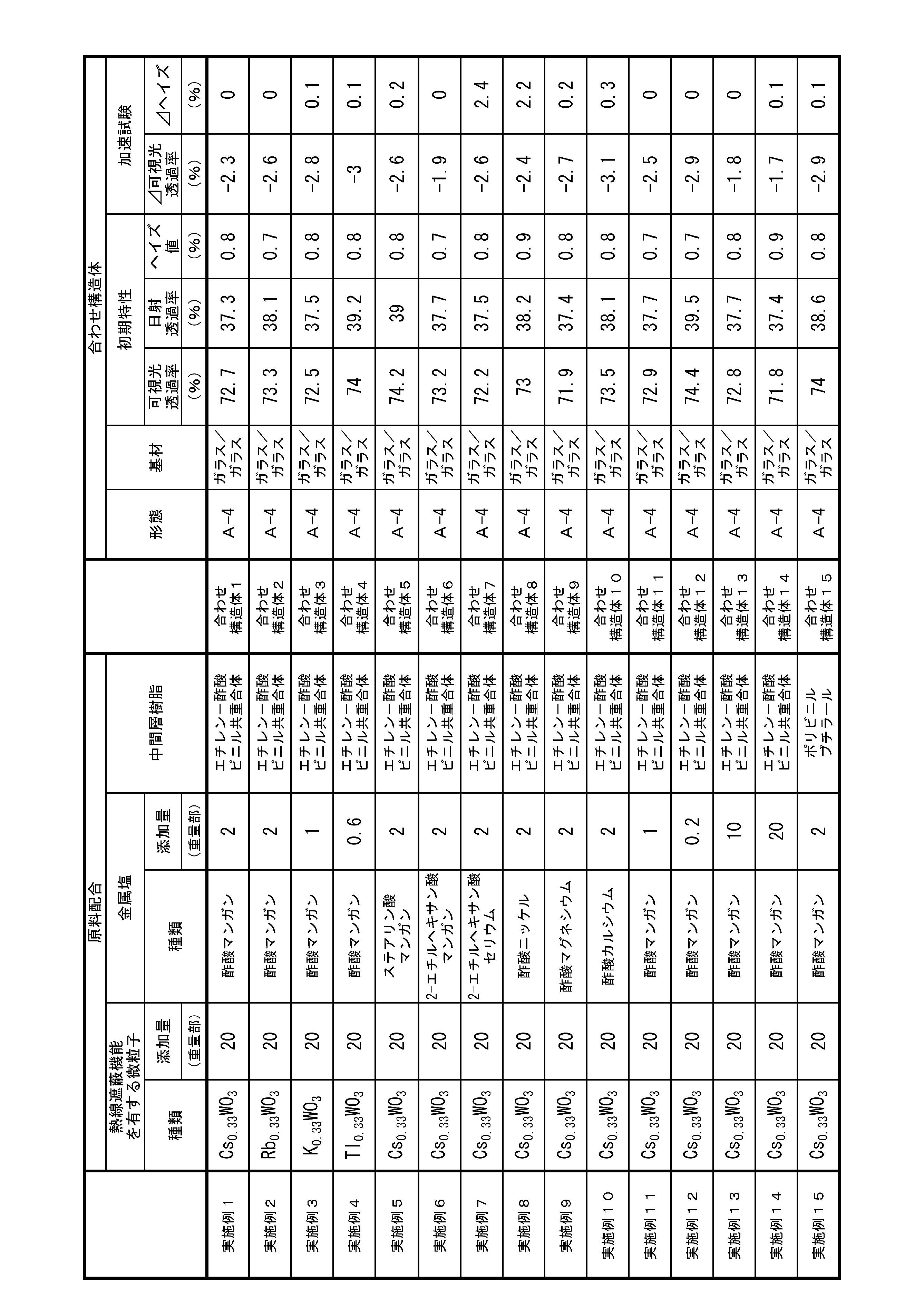


表1~3の結果より、実施例1~38においては、複合タングステン酸化物微粒子へ、カルボン酸の金属塩を適正量添加したことで、高い可視光透過性と、高い熱線遮蔽特性とを有し、ヘイズ値が低く透明にも優れた熱線遮蔽用合わせ構造体1~38が得られた。
なかでも、ナトリウム、カリウム、マグネシウム、カルシウム、マンガン、亜鉛、セシウム、リチウム、ルビジウムのカルボン酸塩を適正量添加した熱線遮蔽用合わせ構造体は、紫外線を2時間照射した加速試験において、初期の可視光透過率に対して、その変化率が半分以下に抑制されるという顕著な効果を知見した。また、紫外線を2時間照射した加速試験において、ヘイズ値の増加が0.3%以下に留まるという効果を知見した。
一方、比較例1、2、4は、カルボン酸の金属塩を添加しなかった、または、添加量が少なすぎたため、加速試験において可視光透過率の変化が増大した。また、比較例3は、カルボン酸の金属塩の添加量が多すぎたため、合わせ構造体として重要な物性である無機ガラスとの密着性が損なわれてしまった。
Cs0.33WO3微粒子(比表面積20m2/g)を20重量部、炭酸ナトリウムを2重量部、4-メチル-2-ペンタノンを58重量部、微粒子分散用分散剤20重量部を混合し、媒体攪拌ミルで分散処理を行ない、平均分散粒子径80nmのCs0.33WO3微粒子と炭酸ナトリウムの分散液を作製した(A2液)。
このA2液と熱硬化樹脂(固形分100%)と4-メチル-2-ペンタノンを十分混合し塗布液とした。この塗布液を、バーコーターを用いてポリエチレンテレフタレートフィルム(PET)上に塗布、成膜し、この膜を130℃/30分間加熱硬化させ、熱線遮蔽膜が形成された熱線遮蔽フィルム基板を得た。
当該熱線遮蔽膜が形成された熱線遮蔽フィルム基板を、2枚の熱線遮蔽機能を有する微粒子を含まない中間膜用エチレン-酢酸ビニル共重合体シート間に配置し、これを2枚の対向する無機ガラスで挟み込み、公知の方法で張り合わせ一体化して(形態A-4)、実施例39に係る熱線遮蔽用合わせ構造体43を得た。作製された構造体43の光学特性を表4に示す。
作製された構造体43を試験サンプルとし、紫外線照射装置を使用し、紫外線を2時間照射した後の可視光透過率の変化とヘイズ値の変化とを測定した。この結果を表4に示す。
Rb0.33WO3微粒子(比表面積20m2/g)を20重量部、炭酸ナトリウムを2重量部、4-メチル-2-ペンタノンを58重量部、微粒子分散用分散剤20重量部を混合し、媒体攪拌ミルで分散処理を行ない、平均分散粒子径80nmのRb0.33WO3微粒子と炭酸ナトリウムの分散液を作製した(B2液)。
このB2液と熱硬化樹脂(固形分100%)と4-メチル-2-ペンタノンを十分混合し塗布液とした。この塗布液を、バーコーターを用いてポリエチレンテレフタレートフィルム(PET)上に塗布、成膜し、130℃/30分間加熱硬化させ、熱線遮蔽膜が形成された熱線遮蔽フィルム基板を得た。
当該熱線遮蔽膜が形成された熱線遮蔽フィルム基板を、2枚の熱線遮蔽機能を有する微粒子を含まない中間膜用エチレン-酢酸ビニル共重合体シート間に配置し、これを2枚の対向する無機ガラスで挟み込み、公知の方法で張り合わせ一体化して(形態A-4)、実施例40に係る熱線遮蔽用合わせ構造体44を得た。作製された構造体44の光学特性を表4に示す。
作製された構造体44を試験サンプルとし、紫外線照射装置を使用し、紫外線を2時間照射した後の可視光透過率の変化とヘイズ値の変化とを測定した。この結果を表4に示す。
K0.33WO3微粒子(比表面積20m2/g)を20重量部、炭酸ナトリウムを4重量部、4-メチル-2-ペンタノンを56重量部、微粒子分散用分散剤20重量部を混合し、媒体攪拌ミルで分散処理を行ない、平均分散粒子径80nmのK0.33WO3微粒子と炭酸ナトリウムの分散液を作製した(C2液)。
このC2液と熱可塑性樹脂(固形分100%)と4-メチル-2-ペンタノンを十分混合し塗布液とした。この塗布液を、バーコーターを用いてポリエチレンテレフタレートフィルム(PET)上に塗布、成膜し、120℃/30分間焼成し、熱線遮蔽膜が形成された熱線遮蔽フィルム基板を得た。
当該熱線遮蔽膜が形成された熱線遮蔽フィルム基板を、2熱線遮蔽機能を有する微粒子を含まない枚の中間膜用エチレン-酢酸ビニル共重合体シート間に配置し、これを2枚の対向する無機ガラスで挟み込み、公知の方法で張り合わせ一体化して(形態A-4)、実施例41に係る熱線遮蔽用合わせ3構造体45を得た。作製された構造体45の光学特性を表4に示す。
作製された構造体45を試験サンプルとし、紫外線照射装置を使用し、紫外線を2時間照射した後の可視光透過率の変化とヘイズ値の変化とを測定した。この結果を表4に示す。
Tl0.33WO3微粒子(比表面積20m2/g)を20重量部、炭酸ナトリウムを0.6重量部、4-メチル-2-ペンタノンを59.4重量部、微粒子分散用分散剤20重量部を混合し、媒体攪拌ミルで分散処理を行ない、平均分散粒子径80nmのTl0.33WO3微粒子と炭酸ナトリウムの分散液を作製した(D2液)。
このD2液とハードコート用紫外線硬化樹脂(固形分100%)と4-メチル-2-ペンタノンを十分間混合し塗布液とした。この塗布液を、バーコーターを用いてポリエチレンテレフタレートフィルム(PET)上に塗布、成膜し、この膜を70℃で2分間乾燥し溶媒を蒸発させた後、高圧水銀ランプで硬化させ、熱線遮蔽膜が形成された熱線遮蔽フィルム基板を得た。
当該熱線遮蔽膜が形成された熱線遮蔽フィルム基板を、2枚の前記熱線遮蔽機能を有する微粒子を含まない中間膜用エチレン-酢酸ビニル共重合体シート間に配置し、これを2枚の対向する無機ガラスで挟み込み、公知の方法で張り合わせ一体化して(形態A-4)、実施例42に係る熱線遮蔽用合わせ構造体46を得た。作製された構造体46の光学特性を表4に示す。
作製された構造体46を試験サンプルとし、紫外線照射装置を使用し、紫外線を2時間照射した後の可視光透過率の変化とヘイズ値の変化とを測定した。この結果を表4に示す。
金属の炭酸塩として、炭酸ナトリウムを炭酸マンガンへ代替した以外は実施例39と同様にして、実施例43に係る熱線遮蔽用合わせ構造体47を得た。作製された構造体47の光学特性を表4に示す。
作製された構造体47を試験サンプルとし、紫外線照射装置を使用し、紫外線を2時間照射した後の可視光透過率の変化とヘイズ値の変化とを測定した。この結果を表4に示す。
金属の炭酸塩として、炭酸ナトリウムを炭酸リチウムへ代替した以外は実施例39と同様にして、実施例44に係る熱線遮蔽用合わせ構造体48を得た。作製された構造体48の光学特性を表4に示す。
作製された構造体48を試験サンプルとし、紫外線照射装置を使用し、紫外線を2時間照射した後の可視光透過率の変化とヘイズ値の変化とを測定した。この結果を表4に示す。
金属の炭酸塩として、炭酸ナトリウムを炭酸ルビジウムへ代替した以外は実施例39と同様にして、実施例45に係る熱線遮蔽用合わせ構造体49を得た。作製された構造体49の光学特性を表4に示す。
作製された構造体49を試験サンプルとし、紫外線照射装置を使用し、紫外線を2時間照射した後の可視光透過率の変化とヘイズ値の変化とを測定した。この結果を表4に示す。
金属の炭酸水酸化物として、炭酸ナトリウムを炭酸水酸化マグネシウムへ代替した以外は実施例39と同様にして、実施例46に係る熱線遮蔽用合わせ構造体50を得た。作製された構造体50の光学特性を表4に示す。
作製された構造体50を試験サンプルとし、紫外線照射装置を使用し、紫外線を2時間照射した後の可視光透過率の変化とヘイズ値の変化とを測定した。この結果を表4に示す。
Cs0.33WO3微粒子(比表面積20m2/g)20重量部に対して、炭酸ナトリウムを1重量部添加した以外は実施例39と同様にして、実施例47に係る熱線遮蔽用合わせ構造体51を得た。作製された構造体51の光学特性を表4に示す。
作製された構造体51を試験サンプルとし、紫外線照射装置を使用し、紫外線を2時間照射した後の可視光透過率の変化とヘイズ値の変化とを測定した。この結果を表4に示す。
Cs0.33WO3微粒子(比表面積20m2/g)20重量部に対して、炭酸ナトリウムを0.2重量部添加した以外は実施例39と同様にして、実施例48に係る熱線遮蔽用合わせ構造体52を得た。作製された構造体52の光学特性を表4に示す。
作製された構造体52を試験サンプルとし、紫外線照射装置を使用し、紫外線を2時間照射した後の可視光透過率の変化とヘイズ値の変化とを測定した。この結果を表4に示す。
Cs0.33WO3微粒子(比表面積20m2/g)20重量部に対して、炭酸ナトリウムを10重量部添加した以外は実施例39と同様にして、実施例49に係る熱線遮蔽用合わせ構造体53を得た。作製された構造体53の光学特性を表4に示す。
作製された構造体53を試験サンプルとし、紫外線照射装置を使用し、紫外線を2時間照射した後の可視光透過率の変化とヘイズ値の変化とを測定した。この結果を表4に示す。
Cs0.33WO3微粒子(比表面積20m2/g)20重量部に対して、炭酸ナトリウムを20重量部添加した以外は実施例39と同様にして、実施例50に係る熱線遮蔽用合わせ構造体54を得た。作製された構造体54の光学特性を表4に示す。
作製された構造体54を試験サンプルとし、紫外線照射装置を使用し、紫外線を2時間照射した後の可視光透過率の変化とヘイズ値の変化とを測定した。この結果を表4に示す。
ビニル系樹脂として、中間膜用エチレン-酢酸ビニル共重合体シートを中間膜用ポリビニルブチラールシートへ代替した以外は実施例39と同様にして、実施例51に係る熱線遮蔽用合わせ構造体55を得た。作製された構造体55の光学特性を表4に示す。
作製された構造体55を試験サンプルとし、紫外線照射装置を使用し、紫外線を2時間照射した後の可視光透過率の変化とヘイズ値の変化とを測定した。この結果を表4に示す。
Cs0.33WO3微粒子(比表面積20m2/g)を20重量部、炭酸ナトリウムを2重量部、トリエチレングリコールジ-2-エチルヘキサノエート(以下、可塑剤aと略称する)を58重量部、微粒子分散用分散剤20重量部を混合し、媒体攪拌ミルで分散処理を行ない、平均分散粒子径80nmのCs0.33WO3微粒子と炭酸ナトリウムの分散液を作製した(E2液)。
可塑剤aを30重量部と、ポリビニルブチラール樹脂を70重量部を混合した組成物へ、所定量のE2液を添加し、当該組成物中におけるCs0.33WO3微粒子の濃度を0.15重量%とした。この組成物を二軸押出機を用いて200℃で混練、Tダイより押出しカレンダーロール法により0.7mm厚のシートとして熱線遮蔽微粒子を含む中間膜を得た。
得られた熱線遮蔽微粒子を含む中間膜を2枚の対向する無機ガラスで挟み込み、公知の方法で張り合わせ一体化して(形態A-1)、実施例52に係る熱線遮蔽用合わせ構造体56を得た。作製された構造体56の光学特性を表5に示す。
作製された構造体56を試験サンプルとし、紫外線照射装置を使用し、紫外線を2時間照射した後の可視光透過率の変化とヘイズ値の変化とを測定した。この結果を表5に示す。
ビニル系樹脂として、ポリビニルブチラール樹脂をエチレン-酢酸ビニル共重合体へ代替した以外は実施例52と同様にして、実施例53に係る熱線遮蔽用合わせ構造体57を得た。作製された構造体57の光学特性を表5に示す。
作製された構造体57を試験サンプルとし、紫外線照射装置を使用し、紫外線を2時間照射した後の可視光透過率の変化とヘイズ値の変化とを測定した。この結果を表5に示す。
2枚の無機ガラスの内1枚をポリカーボネート板に代替した以外は実施例53と同様にして、実施例54に係る熱線遮蔽用合わせ構造体58を得た。作製された構造体58の光学特性を表5に示す。
作製された構造体58を試験サンプルとし、紫外線照射装置を使用し、紫外線を2時間照射した後の可視光透過率の変化とヘイズ値の変化とを測定した。この結果を表5に示す。
実施例39で作製したA2液と熱硬化樹脂(固形分100%)と4-メチル-2-ペンタノンを十分混合し塗布液とした。この塗布液を、バーコーターを用いて無機ガラス上に塗布、成膜し、この膜を130℃/30分間加熱硬化させ、熱線遮蔽膜を得た。
次に、熱線遮蔽膜が形成されていない無機ガラスと熱線遮蔽膜が形成された前記無機ガラスとを上記熱線遮蔽膜が内側になるように対向させ、これら無機ガラス間に熱線遮蔽機能を有する微粒子を含まない中間膜用ポリビニルブチラールシートを配置し、公知の方法で張り合わせ一体化して(形態A-3)、実施例55に係る熱線遮蔽用合わせ構造体59を得た。作製された構造体59の光学特性を表5に示す。
作製された構造体59を試験サンプルとし、紫外線照射装置を使用し、紫外線を2時間照射した後の可視光透過率の変化とヘイズ値の変化とを測定した。この結果を表5に示す。
熱線遮蔽機能を有する微粒子を含まない中間膜用エチレン-酢酸ビニル共重合体シートを、実施例55で作製した熱線遮蔽膜が形成された無機ガラスの熱線遮蔽膜側とポリエチレンテレフタレートフィルム(PET)との間に挟み込み、公知の方法で張り合わせ一体化して、実施例56に係る熱線遮蔽用合わせ構造体60を得た。作製された構造体60の光学特性を表5に示す。
作製された構造体60を試験サンプルとし、紫外線照射装置を使用し、紫外線を2時間照射した後の可視光透過率の変化とヘイズ値の変化とを測定した。この結果を表5に示す。
実施例53で作製した熱線遮蔽微粒子を含む中間膜を、熱線遮蔽微粒子を含まない2枚の中間膜用ポリビニルブチラールシートの間に挟み込み、さらに2枚の対向する無機ガラスで挟み込み、公知の方法で張り合わせ一体化して(形態A-2)、実施例57に係る熱線遮蔽用合わせ構造体61を得た。作製された構造体61の光学特性を表5に示す。
作製された構造体61を試験サンプルとし、紫外線照射装置を使用し、紫外線を2時間照射した後の可視光透過率の変化とヘイズ値の変化とを測定した。この結果を表5に示す。
実施例39で作製したA2液を、Cs0.33WO3微粒子の濃度が0.07重量%となるようにポリカーボネート樹脂へ添加混合し、当該混合物を二軸押出機で混練、Tダイより押出し2mm厚のシートとして熱線遮蔽膜が形成された熱線遮蔽フィルム基板を得た。
当該熱線遮蔽膜が形成された熱線遮蔽フィルム基板を一方の合わせ板とし、もう一方の合わせ板である無機ガラスとの間に、熱線遮蔽機能を有する微粒子を含まない中間膜としてポリビニルブチラールシートを挟み込み、公知の方法で張り合わせ一体化して(形態B-7)、実施例58に係る熱線遮蔽用合わせ構造体62を得た。作製された構造体62の光学特性を表5に示す。
作製された構造体62を試験サンプルとし、紫外線照射装置を使用し、紫外線を2時間照射した後の可視光透過率の変化とヘイズ値の変化とを測定した。この結果を表5に示す。
実施例39で作製したA2液を、Cs0.33WO3微粒子の濃度が0.07重量%となるようにポリエチレンテレフタレート樹脂へ添加混合し、当該混合物を二軸押出機で混練し、Tダイより押出し2mm厚のシートとして熱線遮蔽膜が形成された熱線遮蔽フィルム基板を得た。
当該熱線遮蔽膜が形成された熱線遮蔽フィルム基板を一方の合わせ板とし、もう一方の合わせ板である無機ガラスとの間に、熱線遮蔽機能を有する微粒子を含まない中間膜としてエチレン-酢酸ビニル共重合体シートを挟み込み、公知の方法で張り合わせ一体化して(形態B-7)、実施例59に係る熱線遮蔽用合わせ構造体63を得た。作製された構造体63の光学特性を表5に示す。
作製された構造体63を試験サンプルとし、紫外線照射装置を使用し、紫外線を2時間照射した後の可視光透過率の変化とヘイズ値の変化とを測定した。この結果を表5に示す。
実施例53で作製した熱線遮蔽微粒子を含む中間膜を、合わせ板として実施例58で作製した熱線遮蔽膜が形成された熱線遮蔽フィルム基板と、もう一方の合わせ板である無機ガラスとで挟み込み、公知の方法で張り合わせ一体化して(形態B-1)、実施例60に係る熱線遮蔽用合わせ構造体64を得た。作製された構造体64の光学特性を表5に示す。
作製された構造体64を試験サンプルとし、紫外線照射装置を使用し、紫外線を2時間照射した後の可視光透過率の変化とヘイズ値の変化とを測定した。この結果を表5に示す。
実施例39で作製したA2液と熱硬化樹脂(固形分100%)と4-メチル-2-ペンタノンを十分混合し塗布液とした。この塗布液を、バーコーターを用いて、熱線遮蔽微粒子を含有しない中間膜用エチレン-酢酸ビニル共重合体シート上に塗布、成膜した。この膜を130℃/30分間加熱硬化させ、熱線遮蔽膜が形成された熱線遮蔽機能を有する微粒子を含まない中間膜を得た。この熱線遮蔽膜が形成された中間膜の塗布膜側に熱線遮蔽微粒子を含有しない中間膜用エチレン-酢酸ビニル共重合体シートを配置し、さらに2枚の対向する無機ガラスで挟み込み、公知の方法で張り合わせ一体化して(形態A-5)、実施例61に係る熱線遮蔽用合わせ構造体65を得た。作製された構造体65の光学特性を表5に示す。
作製された構造体65を試験サンプルとし、紫外線照射装置を使用し、紫外線を2時間照射した後の可視光透過率の変化とヘイズ値の変化とを測定した。この結果を表5に示す。
実施例39で作製したA2液と熱硬化樹脂(固形分100%)と4-メチル-2-ペンタノンを十分混合し塗布液とした。ポリエステルフィルムシートの一方の面に剥離層としてポリビニルブチラールシートを形成し、塗布液を、バーコーターを用いてこの剥離層上に塗布、成膜した。この膜を130℃/30分間加熱硬化させ、熱線遮蔽膜を得た。この熱線遮蔽膜上に接着剤層として熱線遮蔽機能を有する微粒子を含まない中間膜用ポリビニルブチラールシートを形成して積層体とし転写フィルム24を得た。
当該転写フィルム24の接着剤層を一方の無機ガラスの合わせ板の内側の面に公知の方法で接着し、前記転写フィルムからポリエステルフィルムシートを剥がす。シートを剥がした剥離層面に熱線遮蔽微粒子を含まない中間膜用ポリビニルブチラールシートを配置し、もう一方の無機ガラスの合わせ板の内側の面と公知の方法で張り合わせ一体化して(形態A-6)、実施例62に係る熱線遮蔽用合わせ構造体66を得た。作製された構造体66の光学特性を表5に示す。
作製された構造体66を試験サンプルとし、紫外線照射装置を使用し、紫外線を2時間照射した後の可視光透過率の変化とヘイズ値の変化とを測定した。この結果を表5に示す。
金属の炭酸塩として、炭酸ナトリウムを炭酸セシウムへ代替した以外は実施例39と同様にして、実施例63に係る熱線遮蔽用合わせ構造体67を得た。作製された構造体67の光学特性を表5に示す。
作製された構造体67を試験サンプルとし、紫外線照射装置を使用し、紫外線を2時間照射した後の可視光透過率の変化とヘイズ値の変化とを測定した。この結果を表5に示す。
金属の炭酸塩として、炭酸ナトリウムを炭酸カリウムへ代替した以外は実施例39と同様にして、実施例64に係る熱線遮蔽用合わせ構造体68を得た。作製された構造体68の光学特性を表6に示す。
作製された構造体68を試験サンプルとし、紫外線照射装置を使用し、紫外線を2時間照射した後の可視光透過率の変化とヘイズ値の変化とを測定した。この結果を表6に示す。
金属の炭酸塩として、炭酸ナトリウムを炭酸カルシウムへ代替した以外は実施例39と同様にして、実施例65に係る熱線遮蔽用合わせ構造体69を得た。作製された構造体69の光学特性を表6に示す。
作製された構造体69を試験サンプルとし、紫外線照射装置を使用し、紫外線を2時間照射した後の可視光透過率の変化とヘイズ値の変化とを測定した。この結果を表6に示す。
金属の炭酸塩として、炭酸ナトリウムを炭酸ストロンチウムへ代替した以外は実施例39と同様にして、実施例66に係る熱線遮蔽用合わせ構造体70を得た。作製された構造体70の光学特性を表6に示す。
作製された構造体70を試験サンプルとし、紫外線照射装置を使用し、紫外線を2時間照射した後の可視光透過率の変化とヘイズ値の変化とを測定した。この結果を表6に示す。
金属の炭酸塩として、炭酸ナトリウムを炭酸ニッケルへ代替した以外は実施例39と同様にして、実施例67に係る熱線遮蔽用合わせ構造体71を得た。作製された構造体71の光学特性を表6に示す。
作製された構造体71を試験サンプルとし、紫外線照射装置を使用し、紫外線を2時間照射した後の可視光透過率の変化とヘイズ値の変化とを測定した。この結果を表6に示す。
金属の炭酸塩として、炭酸ナトリウムを炭酸コバルトへ代替した以外は実施例39と同様にして、実施例68に係る熱線遮蔽用合わせ構造体72を得た。作製された構造体72の光学特性を表6に示す。
作製された構造体72を試験サンプルとし、紫外線照射装置を使用し、紫外線を2時間照射した後の可視光透過率の変化とヘイズ値の変化とを測定した。この結果を表6に示す。
金属の炭酸塩として、炭酸ナトリウムを炭酸銅(II)へ代替した以外は実施例39と同様にして、実施例69に係る熱線遮蔽用合わせ構造体73を得た。作製された構造体73の光学特性を表6に示す。
作製された構造体73を試験サンプルとし、紫外線照射装置を使用し、紫外線を2時間照射した後の可視光透過率の変化とヘイズ値の変化とを測定した。この結果を表6に示す。
金属の炭酸塩として、炭酸ナトリウムを炭酸亜鉛へ代替した以外は実施例39と同様にして、実施例70に係る熱線遮蔽用合わせ構造体74を得た。作製された構造体74の光学特性を表6に示す。
作製された構造体74を試験サンプルとし、紫外線照射装置を使用し、紫外線を2時間照射した後の可視光透過率の変化とヘイズ値の変化とを測定した。この結果を表6に示す。
炭酸ナトリウムを添加しなかった以外は実施例39と同様にして、比較例5に係る熱線遮蔽分散液(以下、K2液と略称する)を作製した。
A2液をK2液に代替した以外は実施例39と同様にして、比較例5に係る熱線遮蔽用合わせ構造体75を得た。作製された構造体75の光学特性を表6に示す。
作製された構造体75を試験サンプルとし、紫外線照射装置を使用し、紫外線を2時間照射した後の可視光透過率の変化とヘイズ値の変化とを測定した。この結果を表6に示す。
Cs0.33WO3微粒子(比表面積20m2/g)20重量部に対して、炭酸ナトリウムを0.1重量部添加した以外は実施例39と同様にして、比較例6に係る熱線遮蔽用合わせ構造体76を得た。作製された構造体76の光学特性を表6に示す。
作製された構造体76を試験サンプルとし、紫外線照射装置を使用し、紫外線を2時間照射した後の可視光透過率の変化とヘイズ値の変化とを測定した。この結果を表6に示す。
Cs0.33WO3微粒子(比表面積20m2/g)20重量部に対して、炭酸ナトリウムを40重量部添加した以外は実施例53と同様にして、比較例7に係る熱線遮蔽分散液(以下、L2液と略称する)を作製した。
実施例53で用いた分散液をL2液に代替した以外は実施例53と同様にして、比較例7に係る熱線遮蔽用合わせ構造体77を得た。作製された構造体77の光学特性を表6に示す。
しかし、金属の炭酸塩の添加量が多すぎたため、構造体77は、無機ガラスと熱線遮蔽微粒子を含む中間膜との密着性が不十分であり、無機ガラスと熱線遮蔽微粒子を含む中間膜が簡単に剥がれてしまう問題が生じた。
よって、加速試験は実施しなかった。
炭酸ナトリウムを添加しなかった以外は実施例52と同様にして、比較例8に係る熱線遮蔽分散液(以下、M2液と略称する)を作製した。
E2液をM2液に代替した以外は実施例52と同様にして、比較例8に係る熱線遮蔽用合わせ構造体78を得た。作製された構造体78の光学特性を表6に示す。
作製された構造体78を試験サンプルとし、紫外線照射装置を使用し、紫外線を2時間照射した後の可視光透過率の変化とヘイズ値の変化とを測定した。この結果を表6に示す。

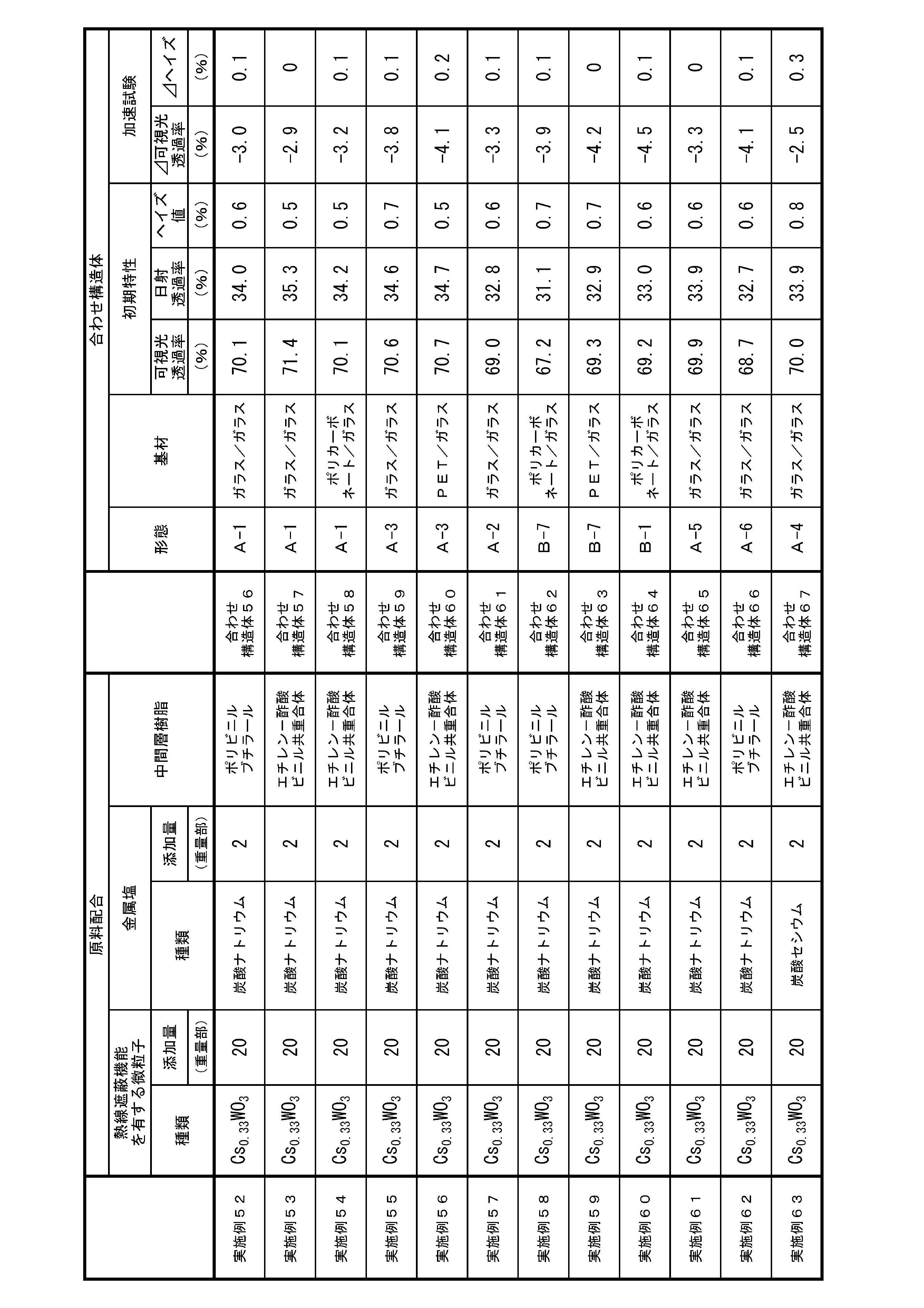
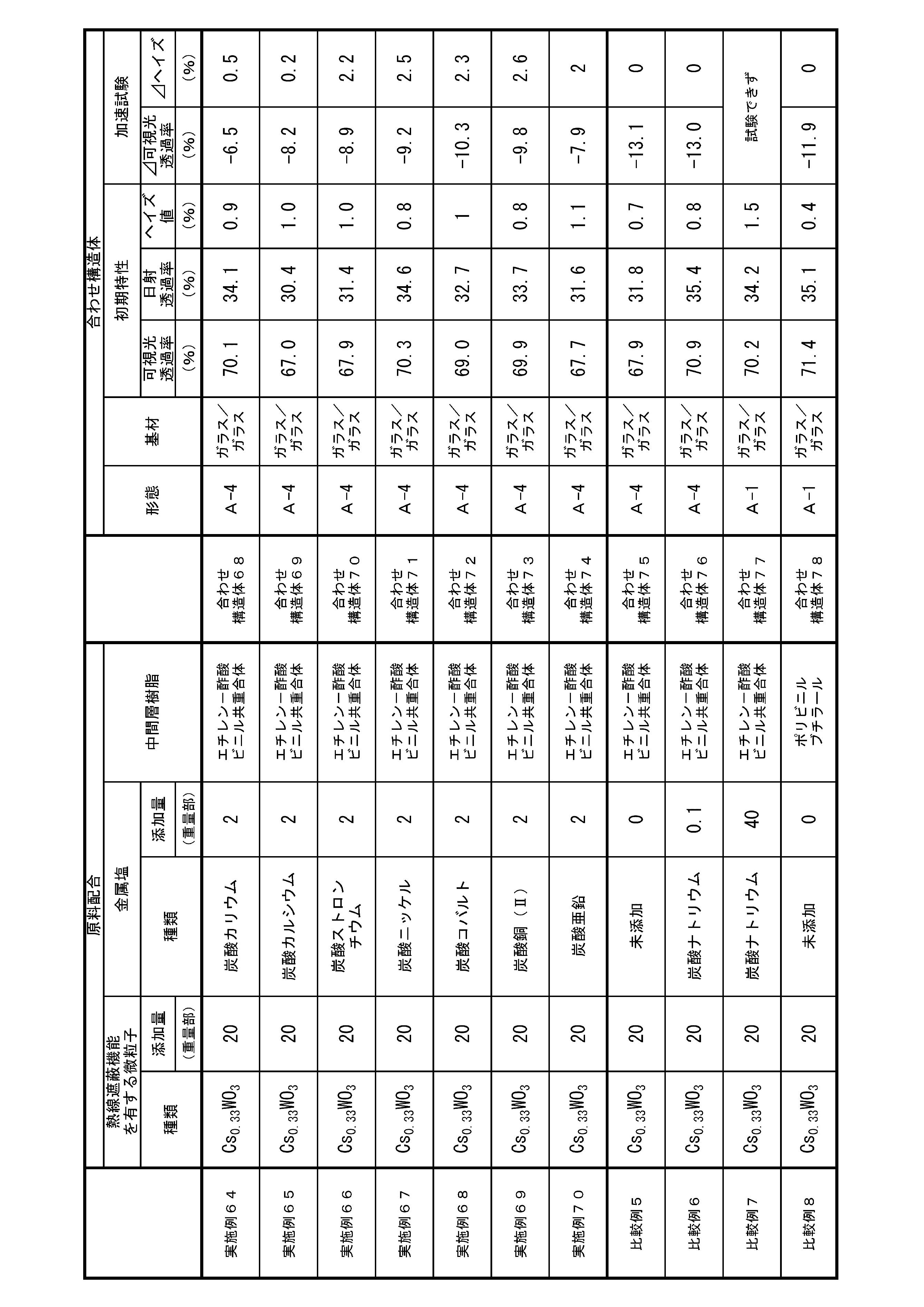
表4~6の結果より、実施例39~70においては、複合タングステン酸化物微粒子へ、金属の炭酸塩または炭酸水酸化物を適正量添加したことで、高い可視光透過性と、高い熱線遮蔽特性とを有し、ヘイズ値が低く透明性にも優れた熱線遮蔽用合わせ構造体43~74が得られた。
なかでも、ナトリウム、カリウム、マグネシウム、マンガン、セシウム、リチウム、ルビジウムの炭酸塩または炭酸水酸化物を適正量添加した実施例39~64に係る熱線遮蔽用合わせ構造体43~68においては、紫外線を2時間照射した加速試験において、初期の可視光透過率に対して、その変化率が半分以下に抑制されるという顕著な効果を知見した。
また、実施例39~64に係る熱線遮蔽用合わせ構造体43~68では、紫外線を2時間照射した加速試験において、ヘイズ値の増加が0.5%以下に留まるという効果を知見した。
一方、比較例5、6、8は、金属炭酸塩または炭酸水酸化物を添加しなかった、または、添加量が少なすぎたため、加速試験において可視光透過率の変化が増大した。また、比較例7は、炭酸塩の添加量が多すぎたため、合わせ構造体として重要な物性である無機ガラスとの密着性が損なわれてしまった。
Cs0.33WO3微粒子(比表面積20m2/g)を20重量部、水酸化ルビジウムn水和物を2重量部、4-メチル-2-ペンタノンを58重量部、微粒子分散用分散剤20重量部を混合し、媒体攪拌ミルで分散処理を行ない、平均分散粒子径80nmのCs0.33WO3微粒子と水酸化ルビジウムn水和物の分散液を作製した(A3液)。
但し、当該水酸化ルビジウムn水和物は、水酸化ルビジウムを70質量%含有している。以下の実施例、比較例においても同様である。
このA3液と熱硬化樹脂(固形分100%)と4-メチル-2-ペンタノンを十分混合し塗布液とした。この塗布液を、バーコーターを用いてポリエチレンテレフタレートフィルム(PET)上に塗布、成膜し、この膜を130℃/30分間加熱硬化させ、熱線遮蔽膜が形成された熱線遮蔽フィルム基板を得た。
当該熱線遮蔽膜が形成された熱線遮蔽フィルム基板を、2枚の熱線遮蔽機能を有する微粒子を含まない中間膜用エチレン-酢酸ビニル共重合体シート間に配置し、これを2枚の対向する無機ガラスで挟み込み、公知の方法で張り合わせ一体化して(形態A-4)、実施例71に係る熱線遮蔽用合わせ構造体79を得た。作製された構造体79の光学特性を表7に示す。
作製された構造体79を試験サンプルとし、紫外線照射装置を使用し、紫外線を2時間照射した後の可視光透過率の変化とヘイズ値の変化とを測定した。この結果を表7に示す。
Rb0.33WO3微粒子(比表面積20m2/g)を20重量部、水酸化ルビジウムn水和物を2重量部、4-メチル-2-ペンタノンを58重量部、微粒子分散用分散剤20重量部を混合し、媒体攪拌ミルで分散処理を行ない、平均分散粒子径80nmのRb0.33WO3微粒子と水酸化ルビジウムn水和物の分散液を作製した(B3液)。
このB3液と熱硬化樹脂(固形分100%)と4-メチル-2-ペンタノンを十分混合し塗布液とした。この塗布液を、バーコーターを用いてポリエチレンテレフタレートフィルム(PET)上に塗布、成膜し、130℃/30分間加熱硬化させ、熱線遮蔽膜が形成された熱線遮蔽フィルム基板を得た。
当該熱線遮蔽膜が形成された熱線遮蔽フィルム基板を、2枚の熱線遮蔽機能を有する微粒子を含まない中間膜用エチレン-酢酸ビニル共重合体シート間に配置し、これを2枚の対向する無機ガラスで挟み込み、公知の方法で張り合わせ一体化して(形態A-4)、実施例72に係る熱線遮蔽用合わせ構造体80を得た。作製された構造体80の光学特性を表7に示す。
作製された構造体80を試験サンプルとし、紫外線照射装置を使用し、紫外線を2時間照射した後の可視光透過率の変化とヘイズ値の変化とを測定した。この結果を表7に示す。
K0.33WO3微粒子(比表面積20m2/g)を20重量部、水酸化ルビジウムn水和物を4重量部、4-メチル-2-ペンタノンを56重量部、微粒子分散用分散剤20重量部を混合し、媒体攪拌ミルで分散処理を行ない、平均分散粒子径80nmのK0.33WO3微粒子と水酸化ルビジウムn水和物の分散液を作製した(C3液)。
このC3液と熱可塑性樹脂(固形分100%)と4-メチル-2-ペンタノンを十分混合し塗布液とした。この塗布液を、バーコーターを用いてポリエチレンテレフタレートフィルム(PET)上に塗布、成膜し、120℃/30分間焼成し、熱線遮蔽膜が形成された熱線遮蔽フィルム基板を得た。
当該熱線遮蔽膜が形成された熱線遮蔽フィルム基板を、2熱線遮蔽機能を有する微粒子を含まない枚の中間膜用エチレン-酢酸ビニル共重合体シート間に配置し、これを2枚の対向する無機ガラスで挟み込み、公知の方法で張り合わせ一体化して(形態A-4)、実施例73に係る熱線遮蔽用合わせ構造体81を得た。作製された構造体81の光学特性を表7に示す。
作製された構造体81を試験サンプルとし、紫外線照射装置を使用し、紫外線を2時間照射した後の可視光透過率の変化とヘイズ値の変化とを測定した。この結果を表7に示す。
Tl0.33WO3微粒子(比表面積20m2/g)を20重量部、水酸化ルビジウムn水和物を0.6重量部、4-メチル-2-ペンタノンを59.4重量部、微粒子分散用分散剤20重量部を混合し、媒体攪拌ミルで分散処理を行ない、平均分散粒子径80nmのTl0.33WO3微粒子と水酸化ルビジウムn水和物の分散液を作製した(D3液)。
このD3液とハードコート用紫外線硬化樹脂(固形分100%)と4-メチル-2-ペンタノンを十分混合し塗布液とした。この塗布液を、バーコーターを用いてポリエチレンテレフタレートフィルム(PET)上に塗布、成膜し、この膜を70℃で2分間乾燥し溶媒を蒸発させた後、高圧水銀ランプで硬化させ、熱線遮蔽膜が形成された熱線遮蔽フィルム基板を得た。
当該熱線遮蔽膜が形成された熱線遮蔽フィルム基板を、2枚の前記熱線遮蔽機能を有する微粒子を含まない中間膜用エチレン-酢酸ビニル共重合体シート間に配置し、これを2枚の対向する無機ガラスで挟み込み、公知の方法で張り合わせ一体化して(形態A-4)、実施例74に係る熱線遮蔽用合わせ構造体82を得た。作製された構造体82の光学特性を表7に示す。
作製された構造体82を試験サンプルとし、紫外線照射装置を使用し、紫外線を2時間照射した後の可視光透過率の変化とヘイズ値の変化とを測定した。この結果を表7に示す。
金属の水酸化物として、水酸化ルビジウムn水和物を水酸化マグネシウムへ代替した以外は実施例71と同様にして、実施例75に係る熱線遮蔽用合わせ構造体83を得た。作製された構造体83の光学特性を表7に示す。
作製された構造体83を試験サンプルとし、紫外線照射装置を使用し、紫外線を2時間照射した後の可視光透過率の変化とヘイズ値の変化とを測定した。この結果を表7に示す。
金属の水酸化物として、水酸化ルビジウムn水和物を水酸化セシウム一水和物へ代替した以外は実施例71と同様にして、実施例76に係る熱線遮蔽用合わせ構造体84を得た。作製された構造体84の光学特性を表7に示す。
作製された構造体84を試験サンプルとし、紫外線照射装置を使用し、紫外線を2時間照射した後の可視光透過率の変化とヘイズ値の変化とを測定した。この結果を表7に示す。
金属の水酸化物として、水酸化ルビジウムn水和物を水酸化ナトリウム一水和物へ代替した以外は実施例71と同様にして、実施例77に係る熱線遮蔽用合わせ構造体85を得た。作製された構造体85の光学特性を表7に示す。
作製された構造体85を試験サンプルとし、紫外線照射装置を使用し、紫外線を2時間照射した後の可視光透過率の変化とヘイズ値の変化とを測定した。この結果を表7に示す。
金属の水酸化物として、水酸化ルビジウムn水和物を水酸化リチウム二水和物へ代替した以外は実施例71と同様にして、実施例78に係る熱線遮蔽用合わせ構造体86を得た。作製された構造体86の光学特性を表7に示す。
作製された構造体86を試験サンプルとし、紫外線照射装置を使用し、紫外線を2時間照射した後の可視光透過率の変化とヘイズ値の変化とを測定した。この結果を表7に示す。
金属の水酸化物として、水酸化ルビジウムn水和物を水酸化マンガン(II)へ代替した以外は実施例71と同様にして、実施例79に係る熱線遮蔽用合わせ構造体87を得た。作製された構造体87の光学特性を表7に示す。
作製された構造体87を試験サンプルとし、紫外線照射装置を使用し、紫外線を2時間照射した後の可視光透過率の変化とヘイズ値の変化とを測定した。この結果を表7に示す。
Cs0.33WO3微粒子(比表面積20m2/g)20重量部に対して、水酸化ルビジウムn水和物を1重量部添加した以外は実施例71と同様にして、実施例80に係る熱線遮蔽用合わせ構造体88を得た。作製された構造体88の光学特性を表8に示す。
作製された構造体88を試験サンプルとし、紫外線照射装置を使用し、紫外線を2時間照射した後の可視光透過率の変化とヘイズ値の変化とを測定した。この結果を表8に示す。
Cs0.33WO3微粒子(比表面積20m2/g)20重量部に対して、水酸化ルビジウムn水和物を0.2重量部添加した以外は実施例71と同様にして、実施例81に係る熱線遮蔽用合わせ構造体89を得た。作製された構造体89の光学特性を表8に示す。
作製された構造体89を試験サンプルとし、紫外線照射装置を使用し、紫外線を2時間照射した後の可視光透過率の変化とヘイズ値の変化とを測定した。この結果を表8に示す。
Cs0.33WO3微粒子(比表面積20m2/g)20重量部に対して、水酸化ルビジウムn水和物を10重量部添加した以外は実施例71と同様にして、実施例82に係る熱線遮蔽用合わせ構造体90を得た。作製された構造体90の光学特性を表8に示す。
作製された構造体90を試験サンプルとし、紫外線照射装置を使用し、紫外線を2時間照射した後の可視光透過率の変化とヘイズ値の変化とを測定した。この結果を表8に示す。
Cs0.33WO3微粒子(比表面積20m2/g)20重量部に対して、水酸化ルビジウムn水和物を20重量部添加した以外は実施例71と同様にして、実施例83に係る熱線遮蔽用合わせ構造体91を得た。作製された構造体91の光学特性を表8に示す。
作製された構造体91を試験サンプルとし、紫外線照射装置を使用し、紫外線を2時間照射した後の可視光透過率の変化とヘイズ値の変化とを測定した。この結果を表8に示す。
ビニル系樹脂として、中間膜用エチレン-酢酸ビニル共重合体シートを中間膜用ポリビニルブチラールシートへ代替した以外は実施例71と同様にして、実施例84に係る熱線遮蔽用合わせ構造体92を得た。作製された構造体92の光学特性を表8に示す。
作製された構造体92を試験サンプルとし、紫外線照射装置を使用し、紫外線を2時間照射した後の可視光透過率の変化とヘイズ値の変化とを測定した。この結果を表8に示す。
Cs0.33WO3微粒子(比表面積20m2/g)を20重量部、水酸化ルビジウムn水和物を2重量部、トリエチレングリコールジ-2-エチルヘキサノエート(以下、可塑剤aと略称する)を58重量部、微粒子分散用分散剤20重量部を混合し、媒体攪拌ミルで分散処理を行ない、平均分散粒子径80nmのCs0.33WO3微粒子と水酸化ルビジウムn水和物の分散液を作製した(E3液)。
可塑剤aを30重量部と、ポリビニルブチラール樹脂を70重量部を混合した組成物へ、所定量のE3液を添加し、当該組成物中におけるCs0.33WO3微粒子の濃度を0.15重量%とした。この組成物を、二軸押出機を用いて200℃で混練、Tダイより押出しカレンダーロール法により0.7mm厚のシートとして熱線遮蔽微粒子を含む中間膜を得た。
得られた熱線遮蔽微粒子を含む中間膜を2枚の対向する無機ガラスで挟み込み、公知の方法で張り合わせ一体化して(形態A-1)、実施例85に係る熱線遮蔽用合わせ構造体93を得た。作製された構造体93の光学特性を表8に示す。
作製された構造体93を試験サンプルとし、紫外線照射装置を使用し、紫外線を2時間照射した後の可視光透過率の変化とヘイズ値の変化とを測定した。この結果を表8に示す。
ビニル系樹脂として、ポリビニルブチラール樹脂をエチレン-酢酸ビニル共重合体へ代替した以外は実施例85と同様にして、実施例86に係る熱線遮蔽用合わせ構造体94を得た。作製された構造体94の光学特性を表8に示す。
作製された構造体94を試験サンプルとし、紫外線照射装置を使用し、紫外線を2時間照射した後の可視光透過率の変化とヘイズ値の変化とを測定した。この結果を表8に示す。
2枚の無機ガラスの内1枚をポリカーボネート板に代替した以外は実施例86と同様にして、実施例87に係る熱線遮蔽用合わせ構造体95を得た。作製された構造体95の光学特性を表8に示す。
作製された構造体95を試験サンプルとし、紫外線照射装置を使用し、紫外線を2時間照射した後の可視光透過率の変化とヘイズ値の変化とを測定した。この結果を表8に示す。
実施例71で作製したA3液と熱硬化樹脂(固形分100%)と4-メチル-2-ペンタノンを十分混合し塗布液とした。この塗布液を、バーコーターを用いて無機ガラス上に塗布、成膜し、この膜を130℃/30分間加熱硬化させ、熱線遮蔽膜を得た。
次に、熱線遮蔽膜が形成されていない無機ガラスと熱線遮蔽膜が形成された前記無機ガラスとを上記熱線遮蔽膜が内側になるように対向させ、これら無機ガラス間に熱線遮蔽機能を有する微粒子を含まない中間膜用ポリビニルブチラールシートを配置し、公知の方法で張り合わせ一体化して(形態A-3)、実施例88に係る熱線遮蔽用合わせ構造体96を得た。作製された構造体96の光学特性を表8に示す。
作製された構造体96を試験サンプルとし、紫外線照射装置を使用し、紫外線を2時間照射した後の可視光透過率の変化とヘイズ値の変化とを測定した。この結果を表8に示す。
熱線遮蔽機能を有する微粒子を含まない中間膜用エチレン-酢酸ビニル共重合体シートを、実施例88で作製した熱線遮蔽膜が形成された無機ガラスの熱線遮蔽膜側とポリエチレンテレフタレートフィルム(PET)との間に挟み込み、公知の方法で張り合わせ一体化して(形態A-3)、実施例89に係る熱線遮蔽用合わせ構造体97を得た。作製された構造体97の光学特性を表8に示す。
作製された構造体97を試験サンプルとし、紫外線照射装置を使用し、紫外線を2時間照射した後の可視光透過率の変化とヘイズ値の変化とを測定した。この結果を表8に示す。
実施例85で作製した熱線遮蔽微粒子を含む中間膜を、熱線遮蔽微粒子を含まない2枚の中間膜用ポリビニルブチラールシートの間に挟み込み、さらに2枚の対向する無機ガラスで挟み込み、公知の方法で張り合わせ一体化して(形態A-2)、実施例90に係る熱線遮蔽用合わせ構造体98を得た。作製された構造体98の光学特性を表8に示す。
作製された構造体98を試験サンプルとし、紫外線照射装置を使用し、紫外線を2時間照射した後の可視光透過率の変化とヘイズ値の変化とを測定した。この結果を表8に示す。
実施例71で作製したA3液を、Cs0.33WO3微粒子の濃度が0.07重量%となるようにポリカーボネート樹脂へ添加混合し、当該混合物を二軸押出機で混練、Tダイより押出し2mm厚のシートとして熱線遮蔽膜が形成された熱線遮蔽フィルム基板を得た。
当該熱線遮蔽膜が形成された熱線遮蔽フィルム基板を一方の合わせ板とし、もう一方の合わせ板である無機ガラスとの間に、熱線遮蔽機能を有する微粒子を含まない中間膜としてポリビニルブチラールシートを挟み込み、公知の方法で張り合わせ一体化して(形態B-7)、実施例91に係る熱線遮蔽用合わせ構造体99を得た。作製された構造体99の光学特性を表9に示す。
作製された構造体99を試験サンプルとし、紫外線照射装置を使用し、紫外線を2時間照射した後の可視光透過率の変化とヘイズ値の変化とを測定した。この結果を表9に示す。
実施例71で作製したA3液を、Cs0.33WO3微粒子の濃度が0.07重量%となるようにポリエチレンテレフタレート樹脂へ添加混合し、当該混合物を二軸押出機で混練し、Tダイより押出し2mm厚のシートとして熱線遮蔽膜が形成された熱線遮蔽フィルム基板を得た。
当該熱線遮蔽膜が形成された熱線遮蔽フィルム基板を一方の合わせ板とし、もう一方の合わせ板である無機ガラスとの間に、熱線遮蔽機能を有する微粒子を含まない中間膜としてエチレン-酢酸ビニル共重合体シートを挟み込み、公知の方法で張り合わせ一体化して(形態B-7)、実施例92に係る熱線遮蔽用合わせ構造体100を得た。作製された構造体100の光学特性を表9に示す。
作製された構造体100を試験サンプルとし、紫外線照射装置を使用し、紫外線を2時間照射した後の可視光透過率の変化とヘイズ値の変化とを測定した。この結果を表9に示す。
実施例86で作製した熱線遮蔽微粒子を含む中間膜を、合わせ板として実施例91で作製した熱線遮蔽膜が形成された熱線遮蔽フィルム基板と、もう一方の合わせ板である無機ガラスとで挟み込み、公知の方法で張り合わせ一体化して(形態B-1)、実施例93に係る熱線遮蔽用合わせ構造体101を得た。作製された構造体101の光学特性を表9に示す。
作製された構造体101を試験サンプルとし、紫外線照射装置を使用し、紫外線を2時間照射した後の可視光透過率の変化とヘイズ値の変化とを測定した。この結果を表9に示す。
実施例71で作製したA3液と熱硬化樹脂(固形分100%)と4-メチル-2-ペンタノンを十分混合し塗布液とした。この塗布液を、バーコーターを用いて、熱線遮蔽微粒子を含有しない中間膜用エチレン-酢酸ビニル共重合体シート上に塗布、成膜した。この膜を130℃/30分間加熱硬化させ、熱線遮蔽膜が形成された熱線遮蔽機能を有する微粒子を含まない中間膜を得た。この熱線遮蔽膜が形成された中間膜の塗布膜側に熱線遮蔽微粒子を含有しない中間膜用エチレン-酢酸ビニル共重合体シートを配置し、さらに2枚の対向する無機ガラスで挟み込み、公知の方法で張り合わせ一体化して(形態A-5)、実施例94に係る熱線遮蔽用合わせ構造体102を得た。作製された構造体102の光学特性を表9に示す。
作製された構造体102を試験サンプルとし、紫外線照射装置を使用し、紫外線を2時間照射した後の可視光透過率の変化とヘイズ値の変化とを測定した。この結果を表9に示す。
実施例71で作製したA3液と熱硬化樹脂(固形分100%)と4-メチル-2-ペンタノンを十分混合し塗布液とした。ポリエステルフィルムシートの一方の面に剥離層としてポリビニルブチラールシートを形成し、塗布液を、バーコーターを用いてこの剥離層上に塗布、成膜した。この膜を130℃/30分間加熱硬化させ、熱線遮蔽膜を得た。この熱線遮蔽膜上に接着剤層として熱線遮蔽機能を有する微粒子を含まない中間膜用ポリビニルブチラールシートを形成して積層体とし転写フィルム25を得た。
当該転写フィルム25の接着剤層を一方の無機ガラスの合わせ板の内側の面に公知の方法で接着し、前記転写フィルムからポリエステルフィルムシートを剥がす。シートを剥がした剥離層面に熱線遮蔽微粒子を含まない中間膜用ポリビニルブチラールシートを配置し、もう一方の無機ガラスの合わせ板の内側の面と公知の方法で張り合わせ一体化して(形態A-6)、実施例95に係る熱線遮蔽用合わせ構造体103を得た。作製された構造体103の光学特性を表9に示す。
作製された構造体103を試験サンプルとし、紫外線照射装置を使用し、紫外線を2時間照射した後の可視光透過率の変化とヘイズ値の変化とを測定した。この結果を表9に示す。
金属の水酸化物として、水酸化ルビジウムn水和物を水酸化カリウムへ代替した以外は実施例71と同様にして、実施例96に係る熱線遮蔽用合わせ構造体104を得た。作製された構造体104の光学特性を表9に示す。
作製された構造体104を試験サンプルとし、紫外線照射装置を使用し、紫外線を2時間照射した後の可視光透過率の変化とヘイズ値の変化とを測定した。この結果を表9に示す。
金属の水酸化物として、水酸化ルビジウムn水和物を水酸化カルシウムへ代替した以外は実施例71と同様にして、実施例97に係る熱線遮蔽用合わせ構造体105を得た。作製された構造体105光学特性を表9に示す。
作製された構造体105を試験サンプルとし、紫外線照射装置を使用し、紫外線を2時間照射した後の可視光透過率の変化とヘイズ値の変化とを測定した。この結果を表9に示す。
金属の水酸化物として、水酸化ルビジウムn水和物を水酸化ストロンチウム八水和物へ代替した以外は実施例71と同様にして、実施例98に係る熱線遮蔽用合わせ構造体106を得た。作製された構造体106の光学特性を表9に示す。
作製された構造体106を試験サンプルとし、紫外線照射装置を使用し、紫外線を2時間照射した後の可視光透過率の変化とヘイズ値の変化とを測定した。この結果を表9に示す。
金属の水酸化物として、水酸化ルビジウムn水和物を水酸化銅(II)へ代替した以外は実施例71と同様にして、実施例99に係る熱線遮蔽用合わせ構造体107を得た。作製された構造体107の光学特性を表9に示す。
作製された構造体107を試験サンプルとし、紫外線照射装置を使用し、紫外線を2時間照射した後の可視光透過率の変化とヘイズ値の変化とを測定した。この結果を表9に示す。
金属の水酸化物として、水酸化ルビジウムn水和物を水酸化ニッケル(II)へ代替した以外は実施例71と同様にして、実施例100に係る熱線遮蔽用合わせ構造体108を得た。作製された構造体108の光学特性を表9に示す。
作製された構造体108を試験サンプルとし、紫外線照射装置を使用し、紫外線を2時間照射した後の可視光透過率の変化とヘイズ値の変化とを測定した。この結果を表9に示す。
金属の水酸化物として、水酸化ルビジウムn水和物を水酸化バリウム八水和物へ代替した以外は実施例71と同様にして、実施例101に係る熱線遮蔽用合わせ構造体109を得た。作製された構造体109の光学特性を表9に示す。
作製された構造体109を試験サンプルとし、紫外線照射装置を使用し、紫外線を2時間照射した後の可視光透過率の変化とヘイズ値の変化とを測定した。この結果を表9に示す。
金属の水酸化物として、水酸化ルビジウムn水和物を水酸化亜鉛へ代替した以外は実施例71と同様にして、実施例102に係る熱線遮蔽用合わせ構造体110を得た。作製された構造体110の光学特性を表9に示す。
作製された構造体110を試験サンプルとし、紫外線照射装置を使用し、紫外線を2時間照射した後の可視光透過率の変化とヘイズ値の変化とを測定した。この結果を表9に示す。
金属の水酸化物として、水酸化ルビジウムn水和物を水酸化コバルトへ代替した以外は実施例71と同様にして、実施例103に係る熱線遮蔽用合わせ構造体111を得た。作製された構造体111の光学特性を表9に示す。
作製された構造体111を試験サンプルとし、紫外線照射装置を使用し、紫外線を2時間照射した後の可視光透過率の変化とヘイズ値の変化とを測定した。この結果を表9に示す。
金属の水酸化物として、水酸化ルビジウムn水和物を水酸化セリウム(IV)へ代替した以外は実施例71と同様にして、実施例104に係る熱線遮蔽用合わせ構造体112を得た。作製された構造体112の光学特性を表9に示す。
作製された構造体112を試験サンプルとし、紫外線照射装置を使用し、紫外線を2時間照射した後の可視光透過率の変化とヘイズ値の変化とを測定した。この結果を表9に示す。
金属の水酸化物として、水酸化ルビジウムn水和物を酸化水酸化鉄(III)へ代替した以外は実施例71と同様にして、実施例105に係る熱線遮蔽用合わせ構造体113を得た。作製された構造体113の光学特性を表9に示す。
作製された構造体113を試験サンプルとし、紫外線照射装置を使用し、紫外線を2時間照射した後の可視光透過率の変化とヘイズ値の変化とを測定した。この結果を表9に示す。
水酸化ルビジウムn水和物を添加しなかった以外は実施例71と同様にして、比較例9に係る熱線遮蔽分散液(以下、K3液と略称する)を作製した。
A3液をK3液に代替した以外は実施例71と同様にして、比較例9に係る熱線遮蔽用合わせ構造体114を得た。作製された構造体114の光学特性を表9に示す。
作製された構造体114を試験サンプルとし、紫外線照射装置を使用し、紫外線を2時間照射した後の可視光透過率の変化とヘイズ値の変化とを測定した。この結果を表9に示す。
Cs0.33WO3微粒子(比表面積20m2/g)20重量部に対して、水酸化ルビジウムn水和物を0.1重量部添加した以外は実施例71と同様にして、比較例10に係る熱線遮蔽用合わせ構造体115を得た。作製された構造体115の光学特性を表9に示す。
作製された構造体115を試験サンプルとし、紫外線照射装置を使用し、紫外線を2時間照射した後の可視光透過率の変化とヘイズ値の変化とを測定した。この結果を表9に示す。
Cs0.33WO3微粒子(比表面積20m2/g)20重量部に対して、水酸化ルビジウムn水和物を40重量部添加した以外は実施例86と同様にして、比較例11に係る熱線遮蔽分散液(以下、L3液と略称する)を作製した。
実施例86で用いた分散液をL3液に代替した以外は実施例86と同様にして、比較例11に係る熱線遮蔽用合わせ構造体116を得た。作製された構造体116の光学特性を表9に示す。
しかし、金属の水酸化物の添加量が多すぎたため、構造体116は、無機ガラスと熱線遮蔽微粒子を含む中間膜との密着性が不十分であり、無機ガラスと熱線遮蔽微粒子を含む中間膜が簡単に剥がれてしまう問題が生じた。
よって、加速試験は実施しなかった。
水酸化ルビジウムn水和物を添加しなかった以外は実施例85と同様にして、比較例12に係る熱線遮蔽分散液(以下、M3液と略称する)を作製した。
E3液をM3液に代替した以外は実施例85と同様にして、比較例12に係る熱線遮蔽用合わせ構造体117を得た。作製された構造体117の光学特性を表9に示す。
作製された構造体117を試験サンプルとし、紫外線照射装置を使用し、紫外線を2時間照射した後の可視光透過率の変化とヘイズ値の変化とを測定した。この結果を表9に示す。


表7~9の結果より、実施例71~105においては、複合タングステン酸化物微粒子へ、金属の水酸化物を適正量添加したことで、高い可視光透過性と、高い熱線遮蔽特性とを有し、ヘイズ値が低く透明性にも優れた熱線遮蔽用合わせ構造体79~113が得られた。
なかでも、ナトリウム、マグネシウム、マンガン、セシウム、リチウム、ルビジウムの水酸化物を適正量添加した実施例71~95に係る熱線遮蔽用合わせ構造体79~103においては、紫外線を2時間照射した加速試験において、初期の可視光透過率に対して、その変化率が半分以下に抑制されるという顕著な効果を知見した。
また、当該実施例71~95に係る熱線遮蔽用合わせ構造体79~103では、紫外線を2時間照射した加速試験において、ヘイズ値の増加が0.3%以下に留まるという効果を知見した。
一方、比較例9、10、12は、金属の水酸化物を添加しなかった、または、添加量が少なすぎたため、加速試験において可視光透過率の変化が増大した。また、比較例11は、金属の水酸化物の添加量が多すぎたため、合わせ構造体として重要な物性である無機ガラスとの密着性が損なわれてしまった。
2.中間層
11.熱線遮蔽機能を有する微粒子
12.中間膜
13.熱線遮蔽膜
14.樹脂フィルム
15.熱線遮蔽機能を有する微粒子を含む樹脂フィルム
16.剥離層
17.フィルムシート
18.接着剤層
20.熱線遮蔽機能を有する微粒子を含有する合わせ板
Claims (16)
- 板ガラス、
プラスチック、
熱線遮蔽機能を有する微粒子と、カルボン酸の金属塩、金属の炭酸塩、金属の炭酸水酸化物、金属の水酸化物から選択される1種以上とを含むプラスチック、から選ばれた2枚の合わせ板間に、
熱線遮蔽機能を有する微粒子と、カルボン酸の金属塩、金属の炭酸塩、金属の炭酸水酸化物、金属の水酸化物から選択される1種以上とを含む中間層を、介在させてなる熱線遮蔽用合わせ構造体であって、
前記熱線遮蔽機能を有する微粒子が、一般式MYWOZ(0.001≦Y≦1.0、2.2≦Z≦3.0)で示され、M元素がCs、Rb、K、Tlのうちの1種類以上であり、且つ六方晶の結晶構造を持ち、粒子直径が1nm以上、800nm以下である複合タングステン酸化物微粒子であり、
さらに、前記カルボン酸の金属塩、金属の炭酸塩、金属の炭酸水酸化物、金属の水酸化物から選択される1種以上を、前記複合タングステン酸化物微粒子100重量部に対して1重量部以上、100重量部以下、含有することを特徴とする熱線遮蔽用合わせ構造体。 - 板ガラス、
プラスチック、
熱線遮蔽機能を有する微粒子と、カルボン酸の金属塩、金属の炭酸塩、金属の炭酸水酸化物、金属の水酸化物から選択される1種以上とを含むプラスチック、から選ばれた合わせ板と、
熱線遮蔽機能を有する微粒子と、カルボン酸の金属塩、金属の炭酸塩、金属の炭酸水酸化物、金属の水酸化物から選択される1種以上とを含むプラスチックの合わせ板と、の間に中間層を介在させてなる熱線遮蔽用合わせ構造体であって、
前記熱線遮蔽機能を有する微粒子が、一般式MYWOZ(0.001≦Y≦1.0、2.2≦Z≦3.0)で示され、M元素がCs、Rb、K、Tlのうちの1種類以上であり、且つ六方晶の結晶構造を持ち、粒子直径が1nm以上、800nm以下である複合タングステン酸化物微粒子であり、
さらに、前記カルボン酸の金属塩、金属の炭酸塩、金属の炭酸水酸化物、金属の水酸化物から選択される1種以上を、前記複合タングステン酸化物微粒子100重量部に対して1重量部以上、100重量部以下、含有することを特徴とする熱線遮蔽用合わせ構造体。 - 前記カルボン酸の金属塩を構成する金属が、ナトリウム、カリウム、マグネシウム、カルシウム、マンガン、セシウム、リチウム、ルビジウム、から選択される少なくとも1種であることを特徴とする請求項1または2のいずれか記載の熱線遮蔽用合わせ構造体。
- 前記カルボン酸の金属塩を構成するカルボン酸が、酢酸、酪酸、プロピオン酸、ヘキサン酸、ステアリン酸、2-エチルヘキサン酸から選択される少なくとも1種であることを特徴とする請求項1から3のいずれか記載の熱線遮蔽用合わせ構造体。
- 前記金属の炭酸塩、または、金属の炭酸水酸化物を構成する金属が、ナトリウム、カリウム、マグネシウム、マンガン、セシウム、リチウム、ルビジウムから選択される少なくとも1種であることを特徴とする請求項1または2のいずれか記載の熱線遮蔽用合わせ構造体。
- 前記金属の水酸化物を構成する金属が、ナトリウム、マグネシウム、マンガン、セシウム、リチウム、ルビジウム、から選択される少なくとも1種であることを特徴とする請求項1または2のいずれか記載の熱線遮蔽用合わせ構造体。
- 前記プラスチックが、ポリカーボネート樹脂またはアクリル樹脂またはポリエチレンテレフタレート樹脂の、シートまたはフィルムであることを特徴とする請求項1から6のいずれか記載の熱線遮蔽用合わせ構造体。
- 前記中間層は、中間膜を有し、
当該中間膜中に、前記熱線遮蔽機能を有する微粒子と、カルボン酸の金属塩、金属の炭酸塩、金属の炭酸水酸化物、金属の水酸化物から選択される1種以上とを含むことを特徴とする請求項1から7のいずれか記載の熱線遮蔽用合わせ構造体。 - 前記中間層は、2層以上の積層した中間膜を有し、
当該中間膜の少なくとも1層中に、前記熱線遮蔽機能を有する微粒子と、カルボン酸の金属塩、金属の炭酸塩、金属の炭酸水酸化物、金属の水酸化物から選択される1種以上とを含むことを特徴とする請求項1から7のいずれか記載の熱線遮蔽用合わせ構造体。 - 前記中間層は、
前記板ガラス、プラスチックから選ばれた2枚の合わせ板の少なくとも一方の内側面に形成された、前記熱線遮蔽機能を有する微粒子と、カルボン酸の金属塩、金属の炭酸塩、金属の炭酸水酸化物、金属の水酸化物から選択される1種以上とを含む熱線遮蔽膜と、
当該熱線遮蔽膜と重なり合う前記中間膜と、を有することを特徴とする請求項1から7のいずれか記載の熱線遮蔽用合わせ構造体。 - 前記中間層は、
前記熱線遮蔽機能を有する微粒子と、カルボン酸の金属塩、金属の炭酸塩、金属の炭酸水酸化物、金属の水酸化物から選択される1種以上とを含む熱線遮蔽膜が、樹脂フィルム基板の片面または両面上に形成された熱線遮蔽フィルム基板、
または、前記熱線遮蔽機能を有する微粒子と、カルボン酸の金属塩、金属の炭酸塩、金属の炭酸水酸化物、金属の水酸化物から選択される1種以上とを含む熱線遮蔽フィルム基板が、
2層以上の積層した前記中間膜の間に積層されていることを特徴とする請求項1から7いずれか記載の熱線遮蔽用合わせ構造体。 - 前記中間層は、前記中間膜の少なくとも一方の面に熱線遮蔽機能を有する微粒子と、カルボン酸の金属塩、金属の炭酸塩、金属の炭酸水酸化物、金属の水酸化物から選択される1種以上とを含む熱線遮蔽膜が、形成されていることを特徴とする請求項1から7のいずれか記載の熱線遮蔽用合わせ構造体。
- 前記中間層は、
前記中間膜または2層以上の積層した前記中間膜と、
接着剤層と、
前記熱線遮蔽機能を有する微粒子と、カルボン酸の金属塩、金属の炭酸塩、金属の炭酸水酸化物、金属の水酸化物から選択される1種以上とが含まれる熱線遮蔽膜と、
剥離層と、の順に積層された積層体を有し、
前記積層体の接着剤層は、前記板ガラス、プラスチックから選ばれた一方の合わせ板の内側面に接着し、
前記積層体の剥離層は、前記中間膜または2層以上の積層した中間膜と接着していることを特徴とする請求項1から7のいずれか記載の熱線遮蔽用合わせ構造体。 - 前記中間層は、中間膜、または、2層以上の積層した中間膜を、有していることを特徴とする請求項2から7のいずれか記載の熱線遮蔽用合わせ構造体。
- 前記中間膜を構成する樹脂は、ビニル系樹脂であることを特徴とする請求項8から14のいずれか記載の熱線遮蔽用合わせ構造体。
- 前記中間膜を構成するビニル系樹脂は、ポリビニルブチラールまたはエチレン-酢酸ビニル共重合体であることを特徴とする請求項15に記載の熱線遮蔽用合わせ構造体。
Priority Applications (4)
| Application Number | Priority Date | Filing Date | Title |
|---|---|---|---|
| EP13803907.8A EP2860163B1 (en) | 2012-06-11 | 2013-06-10 | Heat-shielding ply structure |
| CN201380030834.0A CN104487397B (zh) | 2012-06-11 | 2013-06-10 | 热线遮蔽用夹层结构体 |
| US14/407,328 US10384423B2 (en) | 2012-06-11 | 2013-06-10 | Heat shielding lamination structure |
| KR1020147036816A KR102109705B1 (ko) | 2012-06-11 | 2013-06-10 | 열선 차폐용 적층 구조체 |
Applications Claiming Priority (10)
| Application Number | Priority Date | Filing Date | Title |
|---|---|---|---|
| JP2012131559 | 2012-06-11 | ||
| JP2012-131559 | 2012-06-11 | ||
| JP2012252591 | 2012-11-16 | ||
| JP2012-252591 | 2012-11-16 | ||
| JP2013-070667 | 2013-03-28 | ||
| JP2013-070668 | 2013-03-28 | ||
| JP2013070667A JP5939188B2 (ja) | 2013-03-28 | 2013-03-28 | 熱線遮蔽用合わせ構造体 |
| JP2013070668A JP5939402B2 (ja) | 2013-03-28 | 2013-03-28 | 熱線遮蔽用合わせ構造体 |
| JP2013-094673 | 2013-04-26 | ||
| JP2013094673A JP5939403B2 (ja) | 2012-06-11 | 2013-04-26 | 熱線遮蔽用合わせ構造体 |
Publications (1)
| Publication Number | Publication Date |
|---|---|
| WO2013187350A1 true WO2013187350A1 (ja) | 2013-12-19 |
Family
ID=52629333
Family Applications (1)
| Application Number | Title | Priority Date | Filing Date |
|---|---|---|---|
| PCT/JP2013/065932 Ceased WO2013187350A1 (ja) | 2012-06-11 | 2013-06-10 | 熱線遮蔽用合わせ構造体 |
Country Status (6)
| Country | Link |
|---|---|
| US (1) | US10384423B2 (ja) |
| EP (1) | EP2860163B1 (ja) |
| KR (1) | KR102109705B1 (ja) |
| CN (1) | CN104487397B (ja) |
| TW (1) | TWI576238B (ja) |
| WO (1) | WO2013187350A1 (ja) |
Cited By (2)
| Publication number | Priority date | Publication date | Assignee | Title |
|---|---|---|---|---|
| US10759916B2 (en) | 2017-02-23 | 2020-09-01 | Sumitomo Chemical Company, Limited | Lamp cover |
| US11912878B2 (en) | 2018-12-18 | 2024-02-27 | Sumitomo Metal Mining Co., Ltd. | Method of producing organic-inorganic hybrid infrared absorbing particles and organic-inorganic hybrid infrared absorbing particles |
Families Citing this family (12)
| Publication number | Priority date | Publication date | Assignee | Title |
|---|---|---|---|---|
| EP2953164A1 (en) * | 2013-02-01 | 2015-12-09 | Sumitomo Bakelite Company Limited | Heat conducting sheet and structure |
| EP3192785B1 (en) * | 2014-09-11 | 2021-03-31 | Sekisui Chemical Co., Ltd. | Interlayer for laminated glass, laminated glass, and method for installing laminated glass |
| US10730272B2 (en) * | 2015-06-30 | 2020-08-04 | Sumitomo Metal Mining Co., Ltd. | Heat-ray shielding film, heat-ray shielding laminated transparent substrate, automobile, building, dispersoid, mixed composition, method for manufacturing dispersoid, dispersion liquid, and method for manufacturing dispersion liquid |
| CN109153232B (zh) * | 2015-11-19 | 2021-06-08 | 科勒克斯有限责任公司 | 用于太阳天空模拟照明系统的分层面板结构 |
| CN108884375B (zh) * | 2016-04-01 | 2021-05-11 | 住友金属矿山株式会社 | 红外线吸收材料、红外线吸收材料分散液、红外线吸收材料分散体、红外线吸收材料分散体夹层透明基材、红外线吸收透明基材 |
| WO2018025834A1 (ja) * | 2016-08-05 | 2018-02-08 | 旭硝子株式会社 | 合わせガラス |
| JP6820400B2 (ja) | 2016-10-25 | 2021-01-27 | ヒューレット−パッカード デベロップメント カンパニー エル.ピー.Hewlett‐Packard Development Company, L.P. | 酸化セシウムタングステンナノ粒子および両性イオン性安定剤を含有する分散物および噴射可能な組成物 |
| US11305486B2 (en) | 2016-10-25 | 2022-04-19 | Hewlett-Packard Development Company, L.P. | Dispersion and jettable composition containing metal oxide nanoparticles |
| FR3064546B1 (fr) * | 2017-03-30 | 2019-04-05 | Saint-Gobain Glass France | Vitrage comprenant un seul cordon profile pour la liaison entre deux vitres. |
| FR3064545B1 (fr) * | 2017-03-30 | 2019-04-05 | Saint-Gobain Glass France | Vitrage comprenant au moins un cordon profile pour la liaison entre deux vitres. |
| TWI657932B (zh) * | 2018-04-13 | 2019-05-01 | 億高應用材料股份有限公司 | 複合式隔熱結構 |
| CN113540277B (zh) * | 2021-08-04 | 2022-08-12 | 周丽 | 一种可智能调节的节能玻璃及其制备方法 |
Citations (10)
| Publication number | Priority date | Publication date | Assignee | Title |
|---|---|---|---|---|
| JPH04160041A (ja) | 1990-10-24 | 1992-06-03 | Hitachi Ltd | 自動車用窓ガラス |
| JPH08217500A (ja) | 1995-02-14 | 1996-08-27 | Sumitomo Osaka Cement Co Ltd | 合わせガラス |
| JPH08259279A (ja) | 1995-01-23 | 1996-10-08 | Central Glass Co Ltd | 合せガラス及びその製造方法 |
| JPH10297945A (ja) | 1997-04-28 | 1998-11-10 | Central Glass Co Ltd | 合わせガラス及びその製造方法 |
| JP2001089202A (ja) | 1999-05-17 | 2001-04-03 | Sumitomo Metal Mining Co Ltd | 日射遮蔽合わせガラス |
| JP2009035459A (ja) * | 2007-08-03 | 2009-02-19 | Bridgestone Corp | 積層体 |
| JP2009062411A (ja) * | 2007-09-04 | 2009-03-26 | Bridgestone Corp | 近赤外線遮蔽体、これを用いた積層体及びディスプレイ用光学フィルタ、並びにディスプレイ |
| JP2010202495A (ja) | 2009-02-09 | 2010-09-16 | Sumitomo Metal Mining Co Ltd | 熱線遮蔽合わせガラスおよびその製造方法 |
| JP2011063493A (ja) * | 2009-09-18 | 2011-03-31 | Sumitomo Metal Mining Co Ltd | 近赤外線遮蔽材料微粒子分散体および近赤外線遮蔽体および近赤外線遮蔽材料分散体の製造方法 |
| JP2012224478A (ja) * | 2011-04-14 | 2012-11-15 | Sumitomo Metal Mining Co Ltd | 熱線遮蔽膜とその製造方法、および熱線遮蔽合わせ透明基材 |
Family Cites Families (11)
| Publication number | Priority date | Publication date | Assignee | Title |
|---|---|---|---|---|
| US2456366A (en) * | 1946-07-26 | 1948-12-14 | Du Pont | Plasticized polyvinyl acetal compositions |
| US3434915A (en) * | 1965-11-17 | 1969-03-25 | Du Pont | Glass laminate |
| US5480587A (en) * | 1988-12-21 | 1996-01-02 | Aluminum Company Of America | Materials for use as fire retardant additives |
| DE19916506C1 (de) * | 1999-04-13 | 2000-07-13 | Flachglas Ag | Brandschutzglas |
| CN1649726A (zh) * | 2002-05-03 | 2005-08-03 | 纳幕尔杜邦公司 | 在高透射率下具有控制漫射性能的层压玻璃的夹层复合结构及其制造方法 |
| BRPI0406534B1 (pt) * | 2004-03-16 | 2016-04-05 | Sumitomo Metal Mining Co | estrutura laminada para proteção contra radiação solar |
| EP1977885A1 (en) * | 2007-04-05 | 2008-10-08 | Kuraray Europe GmbH | Interlayer films for laminated glazing containing silica with specific refractive index |
| WO2008149974A1 (ja) * | 2007-06-08 | 2008-12-11 | Bridgestone Corporation | 近赤外線遮蔽体、これを用いた積層体及びディスプレイ用光学フィルタ |
| US8216683B2 (en) * | 2007-08-03 | 2012-07-10 | Solutia Inc. | Interlayers comprising stabilized tungsten oxide agents |
| US8481066B2 (en) * | 2009-07-16 | 2013-07-09 | The Curators Of The University Of Missouri | Scaffold for tissue regeneration in mammals |
| JP5615610B2 (ja) * | 2010-07-12 | 2014-10-29 | 富士フイルム株式会社 | 放射線画像検出装置 |
-
2013
- 2013-06-10 WO PCT/JP2013/065932 patent/WO2013187350A1/ja not_active Ceased
- 2013-06-10 EP EP13803907.8A patent/EP2860163B1/en active Active
- 2013-06-10 TW TW102120639A patent/TWI576238B/zh active
- 2013-06-10 KR KR1020147036816A patent/KR102109705B1/ko active Active
- 2013-06-10 US US14/407,328 patent/US10384423B2/en active Active
- 2013-06-10 CN CN201380030834.0A patent/CN104487397B/zh active Active
Patent Citations (10)
| Publication number | Priority date | Publication date | Assignee | Title |
|---|---|---|---|---|
| JPH04160041A (ja) | 1990-10-24 | 1992-06-03 | Hitachi Ltd | 自動車用窓ガラス |
| JPH08259279A (ja) | 1995-01-23 | 1996-10-08 | Central Glass Co Ltd | 合せガラス及びその製造方法 |
| JPH08217500A (ja) | 1995-02-14 | 1996-08-27 | Sumitomo Osaka Cement Co Ltd | 合わせガラス |
| JPH10297945A (ja) | 1997-04-28 | 1998-11-10 | Central Glass Co Ltd | 合わせガラス及びその製造方法 |
| JP2001089202A (ja) | 1999-05-17 | 2001-04-03 | Sumitomo Metal Mining Co Ltd | 日射遮蔽合わせガラス |
| JP2009035459A (ja) * | 2007-08-03 | 2009-02-19 | Bridgestone Corp | 積層体 |
| JP2009062411A (ja) * | 2007-09-04 | 2009-03-26 | Bridgestone Corp | 近赤外線遮蔽体、これを用いた積層体及びディスプレイ用光学フィルタ、並びにディスプレイ |
| JP2010202495A (ja) | 2009-02-09 | 2010-09-16 | Sumitomo Metal Mining Co Ltd | 熱線遮蔽合わせガラスおよびその製造方法 |
| JP2011063493A (ja) * | 2009-09-18 | 2011-03-31 | Sumitomo Metal Mining Co Ltd | 近赤外線遮蔽材料微粒子分散体および近赤外線遮蔽体および近赤外線遮蔽材料分散体の製造方法 |
| JP2012224478A (ja) * | 2011-04-14 | 2012-11-15 | Sumitomo Metal Mining Co Ltd | 熱線遮蔽膜とその製造方法、および熱線遮蔽合わせ透明基材 |
Non-Patent Citations (1)
| Title |
|---|
| See also references of EP2860163A4 |
Cited By (2)
| Publication number | Priority date | Publication date | Assignee | Title |
|---|---|---|---|---|
| US10759916B2 (en) | 2017-02-23 | 2020-09-01 | Sumitomo Chemical Company, Limited | Lamp cover |
| US11912878B2 (en) | 2018-12-18 | 2024-02-27 | Sumitomo Metal Mining Co., Ltd. | Method of producing organic-inorganic hybrid infrared absorbing particles and organic-inorganic hybrid infrared absorbing particles |
Also Published As
| Publication number | Publication date |
|---|---|
| TWI576238B (zh) | 2017-04-01 |
| KR20150022930A (ko) | 2015-03-04 |
| EP2860163A4 (en) | 2016-01-27 |
| EP2860163A1 (en) | 2015-04-15 |
| US10384423B2 (en) | 2019-08-20 |
| TW201402316A (zh) | 2014-01-16 |
| CN104487397A (zh) | 2015-04-01 |
| KR102109705B1 (ko) | 2020-05-12 |
| US20150158274A1 (en) | 2015-06-11 |
| CN104487397B (zh) | 2018-10-09 |
| EP2860163B1 (en) | 2022-01-19 |
Similar Documents
| Publication | Publication Date | Title |
|---|---|---|
| CN104487397B (zh) | 热线遮蔽用夹层结构体 | |
| JP3985193B2 (ja) | 日射遮蔽用合わせ構造体 | |
| JP5305050B2 (ja) | 熱線遮蔽微粒子含有組成物の製造方法および熱線遮蔽微粒子含有組成物、当該熱線遮蔽微粒子含有組成物を用いた熱線遮蔽膜および当該熱線遮蔽膜を用いた熱線遮蔽合わせ透明基材 | |
| CN105307996B (zh) | 热线屏蔽膜、热线屏蔽夹层透明基材、热线屏蔽树脂片材、汽车及建筑物 | |
| KR101877086B1 (ko) | 열-선 차폐 필름 및 이의 제조방법, 및 열-선 차폐 적층 투명 기재 | |
| TWI698468B (zh) | 熱射線屏蔽膜、熱射線屏蔽層合透明基材、汽車、建物、分散體、混合組成物、及分散體之製造方法、分散液、分散液之製造方法 | |
| JP2010228959A (ja) | 合わせ構造体 | |
| JP2021147295A (ja) | 熱線遮蔽合わせ透明基材 | |
| JP2008290460A (ja) | 日射遮蔽用合わせ構造体 | |
| JP6136819B2 (ja) | 熱線遮蔽用合わせ構造体 | |
| JP6123991B2 (ja) | 熱線遮蔽用合わせ構造体 | |
| JP6187634B2 (ja) | 耐候性を備えた熱線遮蔽膜、耐候性を備えた熱線遮蔽シートまたはフィルム、それらを製造する為の熱線遮蔽微粒子分散液、熱線遮蔽微粒子分散粉 | |
| JP6142945B2 (ja) | 中間層を構成する熱線遮蔽膜、および、中間層を構成する熱線遮蔽膜の製造に用いる熱線遮蔽微粒子分散液および熱線遮蔽微粒子分散粉 | |
| JP5939188B2 (ja) | 熱線遮蔽用合わせ構造体 | |
| JP5939402B2 (ja) | 熱線遮蔽用合わせ構造体 | |
| JP6201127B2 (ja) | 耐候性を備えた熱線遮蔽膜、耐候性を備えた熱線遮蔽シートまたはフィルム、熱線遮蔽微粒子分散液、および熱線遮蔽微粒子分散粉 |
Legal Events
| Date | Code | Title | Description |
|---|---|---|---|
| 121 | Ep: the epo has been informed by wipo that ep was designated in this application |
Ref document number: 13803907 Country of ref document: EP Kind code of ref document: A1 |
|
| NENP | Non-entry into the national phase |
Ref country code: DE |
|
| WWE | Wipo information: entry into national phase |
Ref document number: 14407328 Country of ref document: US |
|
| WWE | Wipo information: entry into national phase |
Ref document number: 2013803907 Country of ref document: EP |
|
| ENP | Entry into the national phase |
Ref document number: 20147036816 Country of ref document: KR Kind code of ref document: A |