WO2013187572A1 - 피부용 자가 주입기구 - Google Patents
피부용 자가 주입기구 Download PDFInfo
- Publication number
- WO2013187572A1 WO2013187572A1 PCT/KR2013/000561 KR2013000561W WO2013187572A1 WO 2013187572 A1 WO2013187572 A1 WO 2013187572A1 KR 2013000561 W KR2013000561 W KR 2013000561W WO 2013187572 A1 WO2013187572 A1 WO 2013187572A1
- Authority
- WO
- WIPO (PCT)
- Prior art keywords
- skin
- needle
- solution
- housing
- self
- Prior art date
- Legal status (The legal status is an assumption and is not a legal conclusion. Google has not performed a legal analysis and makes no representation as to the accuracy of the status listed.)
- Ceased
Links
Images



Classifications
-
- A—HUMAN NECESSITIES
- A61—MEDICAL OR VETERINARY SCIENCE; HYGIENE
- A61M—DEVICES FOR INTRODUCING MEDIA INTO, OR ONTO, THE BODY; DEVICES FOR TRANSDUCING BODY MEDIA OR FOR TAKING MEDIA FROM THE BODY; DEVICES FOR PRODUCING OR ENDING SLEEP OR STUPOR
- A61M5/00—Devices for bringing media into the body in a subcutaneous, intra-vascular or intramuscular way; Accessories therefor, e.g. filling or cleaning devices, arm-rests
- A61M5/178—Syringes
- A61M5/31—Details
- A61M5/3129—Syringe barrels
- A61M5/3137—Specially designed finger grip means, e.g. for easy manipulation of the syringe rod
-
- A—HUMAN NECESSITIES
- A61—MEDICAL OR VETERINARY SCIENCE; HYGIENE
- A61M—DEVICES FOR INTRODUCING MEDIA INTO, OR ONTO, THE BODY; DEVICES FOR TRANSDUCING BODY MEDIA OR FOR TAKING MEDIA FROM THE BODY; DEVICES FOR PRODUCING OR ENDING SLEEP OR STUPOR
- A61M5/00—Devices for bringing media into the body in a subcutaneous, intra-vascular or intramuscular way; Accessories therefor, e.g. filling or cleaning devices, arm-rests
- A61M5/14—Infusion devices, e.g. infusing by gravity; Blood infusion; Accessories therefor
- A61M5/158—Needles for infusions; Accessories therefor, e.g. for inserting infusion needles, or for holding them on the body
-
- A—HUMAN NECESSITIES
- A61—MEDICAL OR VETERINARY SCIENCE; HYGIENE
- A61M—DEVICES FOR INTRODUCING MEDIA INTO, OR ONTO, THE BODY; DEVICES FOR TRANSDUCING BODY MEDIA OR FOR TAKING MEDIA FROM THE BODY; DEVICES FOR PRODUCING OR ENDING SLEEP OR STUPOR
- A61M5/00—Devices for bringing media into the body in a subcutaneous, intra-vascular or intramuscular way; Accessories therefor, e.g. filling or cleaning devices, arm-rests
- A61M5/178—Syringes
- A61M5/30—Syringes for injection by jet action, without needle, e.g. for use with replaceable ampoules or carpules
-
- A—HUMAN NECESSITIES
- A61—MEDICAL OR VETERINARY SCIENCE; HYGIENE
- A61M—DEVICES FOR INTRODUCING MEDIA INTO, OR ONTO, THE BODY; DEVICES FOR TRANSDUCING BODY MEDIA OR FOR TAKING MEDIA FROM THE BODY; DEVICES FOR PRODUCING OR ENDING SLEEP OR STUPOR
- A61M37/00—Other apparatus for introducing media into the body; Percutany, i.e. introducing medicines into the body by diffusion through the skin
-
- A—HUMAN NECESSITIES
- A61—MEDICAL OR VETERINARY SCIENCE; HYGIENE
- A61M—DEVICES FOR INTRODUCING MEDIA INTO, OR ONTO, THE BODY; DEVICES FOR TRANSDUCING BODY MEDIA OR FOR TAKING MEDIA FROM THE BODY; DEVICES FOR PRODUCING OR ENDING SLEEP OR STUPOR
- A61M37/00—Other apparatus for introducing media into the body; Percutany, i.e. introducing medicines into the body by diffusion through the skin
- A61M37/0015—Other apparatus for introducing media into the body; Percutany, i.e. introducing medicines into the body by diffusion through the skin by using microneedles
-
- A—HUMAN NECESSITIES
- A61—MEDICAL OR VETERINARY SCIENCE; HYGIENE
- A61M—DEVICES FOR INTRODUCING MEDIA INTO, OR ONTO, THE BODY; DEVICES FOR TRANSDUCING BODY MEDIA OR FOR TAKING MEDIA FROM THE BODY; DEVICES FOR PRODUCING OR ENDING SLEEP OR STUPOR
- A61M5/00—Devices for bringing media into the body in a subcutaneous, intra-vascular or intramuscular way; Accessories therefor, e.g. filling or cleaning devices, arm-rests
- A61M5/178—Syringes
- A61M5/31—Details
- A61M5/32—Needles; Details of needles pertaining to their connection with syringe or hub; Accessories for bringing the needle into, or holding the needle on, the body; Devices for protection of needles
- A61M5/3295—Multiple needle devices, e.g. a plurality of needles arranged coaxially or in parallel
- A61M5/3297—Needles arranged coaxially
-
- A—HUMAN NECESSITIES
- A61—MEDICAL OR VETERINARY SCIENCE; HYGIENE
- A61M—DEVICES FOR INTRODUCING MEDIA INTO, OR ONTO, THE BODY; DEVICES FOR TRANSDUCING BODY MEDIA OR FOR TAKING MEDIA FROM THE BODY; DEVICES FOR PRODUCING OR ENDING SLEEP OR STUPOR
- A61M5/00—Devices for bringing media into the body in a subcutaneous, intra-vascular or intramuscular way; Accessories therefor, e.g. filling or cleaning devices, arm-rests
- A61M5/14—Infusion devices, e.g. infusing by gravity; Blood infusion; Accessories therefor
- A61M5/142—Pressure infusion, e.g. using pumps
- A61M5/14244—Pressure infusion, e.g. using pumps adapted to be carried by the patient, e.g. portable on the body
- A61M2005/14264—Pressure infusion, e.g. using pumps adapted to be carried by the patient, e.g. portable on the body with means for compensating influence from the environment
-
- A—HUMAN NECESSITIES
- A61—MEDICAL OR VETERINARY SCIENCE; HYGIENE
- A61M—DEVICES FOR INTRODUCING MEDIA INTO, OR ONTO, THE BODY; DEVICES FOR TRANSDUCING BODY MEDIA OR FOR TAKING MEDIA FROM THE BODY; DEVICES FOR PRODUCING OR ENDING SLEEP OR STUPOR
- A61M5/00—Devices for bringing media into the body in a subcutaneous, intra-vascular or intramuscular way; Accessories therefor, e.g. filling or cleaning devices, arm-rests
- A61M5/14—Infusion devices, e.g. infusing by gravity; Blood infusion; Accessories therefor
- A61M5/158—Needles for infusions; Accessories therefor, e.g. for inserting infusion needles, or for holding them on the body
- A61M2005/1585—Needle inserters
-
- A—HUMAN NECESSITIES
- A61—MEDICAL OR VETERINARY SCIENCE; HYGIENE
- A61M—DEVICES FOR INTRODUCING MEDIA INTO, OR ONTO, THE BODY; DEVICES FOR TRANSDUCING BODY MEDIA OR FOR TAKING MEDIA FROM THE BODY; DEVICES FOR PRODUCING OR ENDING SLEEP OR STUPOR
- A61M5/00—Devices for bringing media into the body in a subcutaneous, intra-vascular or intramuscular way; Accessories therefor, e.g. filling or cleaning devices, arm-rests
- A61M5/14—Infusion devices, e.g. infusing by gravity; Blood infusion; Accessories therefor
- A61M5/162—Needle sets, i.e. connections by puncture between reservoir and tube ; Connections between reservoir and tube
- A61M2005/1623—Details of air intake
-
- A—HUMAN NECESSITIES
- A61—MEDICAL OR VETERINARY SCIENCE; HYGIENE
- A61M—DEVICES FOR INTRODUCING MEDIA INTO, OR ONTO, THE BODY; DEVICES FOR TRANSDUCING BODY MEDIA OR FOR TAKING MEDIA FROM THE BODY; DEVICES FOR PRODUCING OR ENDING SLEEP OR STUPOR
- A61M5/00—Devices for bringing media into the body in a subcutaneous, intra-vascular or intramuscular way; Accessories therefor, e.g. filling or cleaning devices, arm-rests
- A61M5/178—Syringes
- A61M5/31—Details
- A61M2005/3117—Means preventing contamination of the medicament compartment of a syringe
- A61M2005/3118—Means preventing contamination of the medicament compartment of a syringe via the distal end of a syringe, i.e. syringe end for mounting a needle cannula
- A61M2005/312—Means preventing contamination of the medicament compartment of a syringe via the distal end of a syringe, i.e. syringe end for mounting a needle cannula comprising sealing means, e.g. severable caps, to be removed prior to injection by, e.g. tearing or twisting
-
- A—HUMAN NECESSITIES
- A61—MEDICAL OR VETERINARY SCIENCE; HYGIENE
- A61M—DEVICES FOR INTRODUCING MEDIA INTO, OR ONTO, THE BODY; DEVICES FOR TRANSDUCING BODY MEDIA OR FOR TAKING MEDIA FROM THE BODY; DEVICES FOR PRODUCING OR ENDING SLEEP OR STUPOR
- A61M37/00—Other apparatus for introducing media into the body; Percutany, i.e. introducing medicines into the body by diffusion through the skin
- A61M37/0015—Other apparatus for introducing media into the body; Percutany, i.e. introducing medicines into the body by diffusion through the skin by using microneedles
- A61M2037/0023—Drug applicators using microneedles
Definitions
- the present invention relates to a self-injection device for skin improvement or beauty by penetrating a solution having a predetermined effect in the skin, and more specifically, it is possible to lower the manufacturing cost by forming a light, thin and simple structure of a stamp type. It can be used easily and conveniently at home at low price, and it is a self-injection device for skin that can maximize the efficacy while minimizing solution loss by directly injecting the solution evenly while the needle penetrates into the epidermal and dermal layers of the skin. It is about.
- human skin is divided into epidermal (dermal) layer, dermis (endodermal) layer and subcutaneous tissue layer.
- Healthy young skin is filled with collagen, elastin and the like about 80% of the dermal layer.
- the dermal layer significantly reduces the amount of collagen and elastin (constriction), resulting in thinning of the dermal layer, resulting in dry skin or wrinkles, thereby reducing the elasticity of the skin. Therefore, in order to maintain the elastic skin, various nutritional substances, such as vitamin C and peptides (functional cosmetics), which help to produce or help collagen and elastin, have been applied to the skin to prevent them.
- the roller is made by laminating at least one disc disk, at least one of the microneedle is built into the disc disk or one surface It is proposed a microneedle roller, characterized in that the predetermined length of one end of the microneedle is exposed to the outer surface of the roller.
- the handle bar consisting of a rectangular parallelepiped-shaped housing having an open upper surface, and a rod extending downward from the bottom of the housing; A flat cover coupled to an upper surface of the housing and having a plurality of needle holes arranged at equal intervals; A stamp-type skin stimulator has been proposed, each of which is mounted to the needle hole and has an end portion exposed to the needle hole.
- the mechanism mentioned in the above prior art has needles protruding to a predetermined length on the outer circumferential surface of the roller and one surface of the stamp to contact the roller and the stamp with the skin to artificially form the holes through the epidermal and dermal layers of the skin.
- the nutritional substance has the advantage of increasing penetration into the dermal layer to some extent, but in the case of rollers, the needle does not come into vertical contact with the skin, causing damage to the epidermal and dermal layers, which aggravates the pain of the user, especially the scalp or hair. If you have a lot of hair, there is a problem that the hair is tangled between the needles.
- the needle improves the user's pain and tangled hair through the vertical contact with the skin, but after forming artificial holes in the epidermal and dermal layers like a roller, the nutrients are applied to the surface of the epidermal layer.
- the amount reached (absorbed) into the dermis is only a very low level of total content. That is, even though the needle artificially forms a hole passing through the epidermal and dermal layers of the skin, the skin of the human body basically has a barrier function to protect it from the outside, so that the hole is immediately closed. For example, when the skin is burned, the damaged skin is not killed, but since the damaged skin loses its barrier function, various bacteria penetrate into the skin and die from infection due to this. By simply forming a hole through the epidermal and dermal layers of the skin, there is a limit to more effectively penetrating nutrients to the dermis without loss.
- the stamp head 106a is attached to the body 103a and the length adjusting groove 103b.
- the height can be adjusted (determining the length of the saliva exposure), and the spring 105a is placed in the body so that the microneedle (107a) can quickly exit the skin and exit the saliva.
- an automatic skin micro-channel stamp that can be adjusted between 0.20mm ⁇ 2.3mm the depth that is inserted into the skin off the stamp head 106a in contact with the.
- the mechanism mentioned in the prior art allows the needle to be hidden inside the stamp and to control the penetration depth of the needle. Then, the stamp is in close contact with the skin, the user presses the operating tool by hand and protrudes to artificially form a hole through the epidermal and dermal layers of the skin, it is made of a structure that is undone by the spring.
- a mechanism is only a part of an improvement in the stamp mechanism mentioned in the former, there is no fundamental improvement to improve the penetration of nutrients, so the same problem occurs as before. That is, even though the needle artificially forms a hole passing through the epidermal and dermal layers of the skin, the skin of the human body basically has a barrier function to protect it from the outside, so that the hole is immediately closed. Therefore, simply forming a hole through the epidermal and dermal layers of the skin is limited to more effectively penetrate the nutrients without loss to the dermis.
- auxiliary devices such as a meso-gun using a needle along with a cellar using a laser.
- Cellars evenly drills 2,000 to 10,000 holes in the skin at intervals of 0.3 mm to 1.0 mm to the depth of 0.1 mm to 1.5 mm so that the laser beam Meso-gun is a GUN-type medical device with microneedles that injects dead cells into perforated dead cells.
- the laser beam Meso-gun is a GUN-type medical device with microneedles that injects dead cells into perforated dead cells. It is a medical device that enhances.
- These medical devices are effective in helping dermal therapy and reaching functional cosmetics and actives to the dermis layer, but have the disadvantage of being quite bulky and very expensive. Above all, there is a problem that can not be used without a precise diagnosis and treatment of a doctor by visiting a dermatologist.
- the present invention is to fundamentally solve the conventional problems as described above, the manufacturing cost can be lowered by forming a stamp-type light and simple structure, can be used more easily and conveniently at home at a low price, the skin
- the purpose of the present invention is to provide a self-injection device for skin that can maximize the efficacy while minimizing the loss of solution by directly injecting the solution uniformly while the needle penetrates into the epidermal and dermal layers.
- one aspect of the present invention provides a self-injection apparatus for skin improvement or beauty by infiltrating a solution having a predetermined effect in the skin: having a space to accommodate the solution therein, and An accommodation part having an intake port for sucking only air and an outlet port open to discharge the solution at the other end; A pumping unit coupled to the discharge port of the receiving unit and having an airless pump discharging the solution in a vertical motion in the center thereof; And an injection unit coupled to communicate with the airless pump of the pumping unit and penetrating the solution discharged in the vertical motion into the skin.
- the receiving portion according to the present invention is characterized in that it comprises a cover through the suction hole with the packing flowing in the space while sealing the solution of the inlet.
- the injection unit according to the present invention includes a housing having a fixture and an inclined sphere coupled to the airless pump, a needle portion having a needle groove and a needle in the lower portion of the housing, and a fixed groove fixed to the housing and the needle portion; Characterized in that it consists of a fixing part having a fixing protrusion.
- the housing according to the present invention is characterized in that the outer peripheral surface further comprises a rubber grip or concave-convex to prevent the slip while improving the grip feeling from the user.
- the housing according to the invention is characterized in that it further comprises at least one fixing protrusion and the slide groove on the upper inner peripheral surface to prevent rotation from the pumping portion.
- Another aspect of the present invention is a self-injection device for skin improvement or beauty by penetrating a solution having a predetermined effect in the skin: provided with a protrusion so that the user can grip, having one or more steps below Handle portion having a coupling projection; A packing part detachably provided at a lower portion of the handle part and having a coupling groove fixedly engaged with the coupling protrusion; And an injection part coupled to the packing part to be hermetically coupled and discharging the solution by pressurizing the handle part to penetrate into the skin.
- the handle portion according to the present invention is provided with a rubber grip or irregularities on the outer peripheral surface to prevent the slip while improving the grip feeling from the user.
- the injection unit according to the present invention is coupled to the packing portion and the housing having a fixture and a slope and a space for receiving a solution, a needle portion having a needle groove and needle in the lower portion of the housing, the housing and needle Characterized in that it consists of a fixing portion having a fixing groove and a fixing protrusion to be fixed.
- the needle groove of the needle portion according to one side or the other side of the present invention is characterized in that it comprises a fixing groove for inserting and fixing the needle, the guide groove to guide the needle safely to the center of the top of the fixing groove.
- the needle portion by one side or the other side of the present invention includes a plurality of needles protruding to a predetermined length so as to penetrate into the skin, any one or more of them further comprises a non-projected needle to contact the surface of the skin Characterized in that.
- the fixing part by one side or the other side of the present invention is characterized in that it further fills the curing agent to minimize the waste of the solution by blocking the space while fixing the needle on the inclined sphere of the housing.
- the housing according to one side or the other side of the present invention is characterized in that it further comprises a safety cap via a locking projection coupled to block the inflow of bacteria or foreign substances while protecting the needle portion.
- the present invention can reduce the manufacturing cost by forming a stamp-type light and simple structure, can be easily and conveniently used at home at a low price, the needle penetrates into the epidermal and dermal layers of the skin In this case, the solution is injected directly and uniformly to minimize the loss of the solution while providing the effect of maximizing efficacy.
- FIG. 1 is a perspective view showing an injection device according to one aspect of the invention as a whole.
- Figure 2 is an exploded view showing a separate injection device according to one aspect of the present invention.
- Figure 3 is an exploded view showing the main portion of the injection device in accordance with one aspect of the present invention.
- Figure 4 is a cross-sectional view showing the injecting device according to one aspect of the present invention.
- FIG. 5 is a block diagram showing an embodiment according to an aspect of the present invention.
- FIG. 6 is a configuration diagram showing a modification according to one aspect of the present invention.
- Figure 7 is a cross-sectional view showing the incision as a whole the injection mechanism according to another aspect of the present invention.
- Figure 8 is an exploded view showing the main portion of the injection device according to another aspect of the present invention.
- FIG. 9 is a block diagram showing an embodiment according to another aspect of the present invention.
- 10 to 12 is an injection state showing the state of use of the injection mechanism in the present invention.
- Figure 13 is a schematic diagram showing a brief use state of the injection device according to the present invention.
- the present invention relates to a self-injection device for skin improvement or cosmetic by penetrating the solution (2) having a predetermined effect in the skin (1), one side is the receiving portion 10 and the pumping portion 20 and Main part of the injection unit 30, the other side is related to the self-injection device for the skin having the handle portion 10 and the packing portion 20 and the injection portion 30 as the main configuration. That is, one side and the other side of the present invention is to use the same injection portion 30, selectively between the receiving portion 10 and the pumping portion 20 or the handle portion 10 and the packing portion 20 to interlock therewith Since it can use, it demonstrates based on an Example below.
- the self-injection device is a new concept drug delivery device that injects the solution 2 in a state where a new passage is made directly through the epidermal layer 1a and the dermal layer 1b of the skin 1. That is, by providing a solution (2) having excellent efficacy for improving skin and beauty of skin, which has been verified by KFDA on the apparatus of the present invention in a pre-accepted state, natural wound healing action is performed by injecting itself by applying cosmetics at home. It is an anti-aging solution (solution) device that can achieve the same or more effect as laser peeling or peeling procedure without causing damage to the epidermal layer 1a of the skin 1.
- the solution (2) mentioned in the present invention is hyaluronic acid, vitamin C, collagen, elastin, arbutin, kojic acid, peptide series, etc., having excellent efficacy on whitening or anti-linking and hair (scalp) related to skin improvement or skin beauty.
- Use the ingredients of are available, and new ingredients to be developed in the future.
- it is not recommended to use a solution classified as a medicine such as a skin disease that requires a doctor's consultation or prescription.
- the present invention may be provided to the user in various ways and components without departing from medical law.
- Receiving portion 10 has a space 11 to accommodate the solution (2) therein, the inlet opening 12 for sucking only air at one end and the outlet opening so that the solution (2) is discharged at the other end (15) is provided.
- Receptacle 10 is a container for discharging while receiving the solution (2) having excellent efficacy for skin improvement and skin beauty, as shown in Figs. 1 and 2, the inside having a predetermined volume that can safely contain the solution (2)
- a space 11 is provided, and one end and the other end have a structure having an inlet 12 and an outlet 15.
- the accommodating part 10 covers the solution 14 through the suction hole 14a together with the packing 13 flowing in the space 11 while sealing the solution 2 of the inlet 12. It is provided.
- the inlet 12 is formed such that the solution 2 contained in the space 11 is sealed from the outside as shown in FIG. 10 so that only the air is sucked so that the solution 2 is discharged to the outlet 15 by the pumping unit 20 described later.
- the cover 14 is provided with the packing 13.
- the packing 13 is a soft rubber material that completely seals the inlet 12 of the accommodating part 10 to prevent the solution 2 from being discharged to the outside
- the cover 14 is the inlet of the accommodating part 10. It is coupled to the fixed state 12 and provided with at least one suction hole (14a) to suck the air in the center. That is, as shown in FIG. 10, when the solution 2 is discharged to the outlet 15 by the pumping part 20, the packing 13 flows downward by the volume of the solution 2 discharged by the pressure difference, and flows. The air is sucked into the suction hole 14a of the cover 14 by the sealed packing 13. As such, the solution 13 may be discharged while the inside of the space 11 is sealed by the packing 13 and the cover 14 provided at the suction port 12 from the outside.
- the outlet 15 is protruded to a predetermined length so that the pumping unit 20 can be coupled, the outer peripheral surface is provided with a spiral so that the pumping unit 20 is detachable from the receiving unit 10.
- the spiral is omitted.
- the pumping unit 20 is coupled to communicate with the outlet 15 of the receiving portion 10, and has an airless pump 21 for discharging the solution (2) in the vertical movement in the center.
- the pumping unit 20 is coupled to the outlet 15 of the receiving unit 10 as shown in FIGS. 1 and 2 to discharge the solution 2 contained in the space 11 to the outside, and the solution ( 2) has a structure provided with an airless pump 21 for discharging.
- the pumping unit 20 includes a casing to be coupled to the outlet 15 of the accommodation unit 10, and an airless pump 21 is provided therein.
- the airless pump 21 is composed of a cylinder on which the spring is strongly held together with the one-way valve, and a nozzle that flows up and down while receiving the elastic force of the spring inside the cylinder. That is, the solution 2 is introduced into the cylinder through a valve provided at one end of the cylinder as shown in FIG. 10, and the introduced solution 2 is not discharged again by the valve. In this state, when the nozzle flows upward, the volume of the introduced solution 2 decreases and moves to the inside of the nozzle to completely discharge the outside. Then, the nozzle is retracted by the spring to allow the solution 2 to flow back into the cylinder.
- the inner circumferential surface of the casing is provided with a spiral groove so as to be coupled to the spiral of the discharge port 15, and one end is provided with a seal for engaging in communication with one surface of the discharge port 15 to be in communication.
- the spiral groove is omitted when the receiving portion 10 and the pumping portion 20 are integrated as in the outlet 15 described above.
- the casing is banded to the outer circumferential surface of the outlet port 15 to integrally couple them.
- the receiving unit 10 and the pumping unit 20 is formed in a separate type, the user can separate the receiving unit 10 and the pumping unit 20, and then refill the solution 2, but are formed integrally.
- the solution (2) Once the solution (2) has been used, it must be disposed of (recycled). That is, it is preferable to form it integrally based on stability, such as bacterial infection, but there are many cases where it may be refilled and used according to the component of the solution 2 and the range of use.
- the separate type can easily detach (separate) the receiving part 10 and the pumping part 20 in the process of recycling them, thereby greatly shortening the process. In any case, it will be apparent to those skilled in the art that based on the fairness and ease of use of manufacturing and recycling can be selectively adopted and provided based on the most efficient way.
- the injection unit 30 is coupled in communication with the airless pump 21 of the pumping unit 20, and infiltrate the solution 2 discharged in the vertical movement into the skin (1).
- the injection part 30 penetrates the solution 2 discharged by the pumping part 20 into the skin 1 as shown in FIGS. 1 and 2, and is provided to be coupled to communicate with the airless pump 21.
- the injection portion 30 is a housing 31 having a fixture (31a) and the inclined sphere (31b) coupled to the airless pump 21, and a needle groove in the lower portion of the housing 31 Needle portion 33 having a portion 33a and needle 33b, and a fixing portion 35 having a fixing groove 35a and a fixing protrusion 35b to fix the housing 31 and the needle portion 33 to each other. Is done.
- the housing 31 induces the solution 2 contained in the accommodating part 10 to be discharged to the skin 1, and communicates with one end of the pumping part 20 while maintaining airtightness. It is equipped to be combined with. That is, the housing 31 is integrally provided with a fastener 31a having a jaw of two stages so that one end of the airless pump 21 and an interference fit (detachable) are integrally formed as shown in FIG. 3, and the fastener 31a is a user. By transferring the pressing force by the airless pump 21 to move up and down to induce the solution (2) to be discharged.
- the housing 31 is integrally provided with an inclined sphere (31b) extending at a predetermined angle to the lower portion of the fixture (31a), this inclined sphere (31b) in conjunction with the needle portion 33 to guide the needle (33b) Provide space to accommodate.
- the reason why the inclined port 31b is formed to be inclined at a predetermined angle is to induce the solution 2 discharged from the airless pump 21 to induce a plurality of needles 33b to be dispersed at the same discharge amount. This will be described later in detail. Of course, it does not exclude that it may be formed as a straight sphere instead of the inclined sphere (31b) in some cases.
- the housing 31 further includes a rubber grip 32a or unevenness 32b on the outer circumferential surface to prevent slippage while improving the grip feeling from the user.
- the housing 31 guides the solution 2 contained in the accommodating part 10 to be discharged to the skin 1, and the rubber grip 32a or the concave-convex surface on the outer circumferential surface to enable stable injection in a state in which the user grips by hand. 32b is provided.
- the rubber grip 32a is a soft rubber material further attached to the outer circumferential surface as shown in FIG. 5A, and guides the user to grip smoothly with a predetermined cushion and prevents slippage.
- the rubber grip 32a may form a vertical, horizontal, or lattice-shaped emboss, and may be formed in an overall curved surface.
- Concave-convex (32b) is formed integrally with the user's finger engaging protrusions on the outer circumferential surface as shown in Figure 5b, to guide the user to grip safely without burden to the user's hand when gripping and to prevent slipping.
- the irregularities 32b may be formed in the form of a fine V-groove in the form of X in addition to those shown in the figure, and may be formed in an overall curved surface.
- the rubber grip 32a and the concave-convex 32b may be formed independently of each other, but may be formed in parallel to prevent more improved grip and slip.
- those skilled in the art can form and further attach in various shapes and shapes within the range to prevent grip and slipping.
- the housing 31 is characterized in that it further comprises at least one fixing protrusion (32c) and the slide groove (32d) on the upper inner peripheral surface to prevent rotation from the pumping portion (20).
- the housing 31 is coupled to the pumping unit 20 to perform a vertical movement as shown in FIG. 5A, and includes a fixing protrusion 32c and a slide groove 32d to prevent rotation from the pumping unit 20, respectively.
- the fixing protrusion 32c is formed on the inner circumferential surface of the housing 31, and the slide groove 32d is formed on the outer circumferential surface of the airless pump 21. That is, when the housing 31 and the airless pump 21 are coupled to each other, the fixing protrusion 32c is engaged with the slide groove 32d, so the vertical movement is possible, but the rotation is impossible. Therefore, as the user is prevented from rotating while the needle 33b penetrates into the skin 1, damage to the skin 1 from the needle 33b can be suppressed.
- the needle part 33 injects the solution 2 discharged from the airless pump 21 into the skin 1 as shown in FIGS. 3 and 4, and is tightly coupled to the lower part of the housing 31. That is, the needle part 33 has a plurality of needle grooves 33a radially inside as shown in FIG. 3, the needle grooves 33a tightly fix the needles 33b and the needles 33b are discharged solutions.
- (2) is injected into the skin (1).
- the needle part 33 is fixed in a state where the needle 33b passes through the needle groove 33a from the top and protrudes about 0.25 to 0.6 mm in length to the bottom surface, thereby forming the epidermal layer 1a or the dermal layer ( Infiltrate into 1b).
- one end of the needle 33b protruding to the lower surface of the needle part 33 is preferably formed to be relatively sharp to easily penetrate into the skin 1.
- the needle 33b is formed of a hollow body having a conduit in the center, such as a needle, to directly inject the solution 2 discharged from the airless pump 21 into the skin 1.
- the needle groove (33a) of the needle portion 33 is a fixing groove (34a) for inserting and fixing the needle 33b, the needle 33b to the top of the fixing groove 34a to the center It has a guide groove (34b) to guide safely.
- the needle groove 33a is provided to be divided into the fixing groove 34a and the guide groove 34b as shown in FIG. 3, and the fixing groove 34a is vertical so that the needle 33b injects the solution 2 into the skin 1. It is provided to be fixed in the direction, the guide groove 34b is provided to be inclined at a predetermined angle so that the needle 33b is safely bent to the center so as to correspond to the inclined sphere (31b).
- the inclined sphere 31b is to induce the solution 2 discharged from the airless pump 21 to cause the plurality of needles 33b to be dispersed at the same discharge amount.
- the plurality of needles 33b are fixed fixtures ( Most preferably, all are collected directly below 31a). Above all, since the plurality of needles 33b are positioned closest to each other on the fixture 31a, the needles 2b can be transferred directly onto the needles 33b at the same time as the discharge of the solution 2 from the airless pump 21 and the solution 2 Waste can be minimized.
- the needle portion 33 is to be coupled to the housing 31, the needle 33b as shown in Figure 4 should be bent to assemble to the center, so the guide groove 34b is the needle 33b is fixed groove 34a To bend more safely and naturally. If the needle 33b is bent to correspond to the inclined hole 31b in a state in which the needle 33b is fixed only by the fixing groove 34a without having a separate guide groove 34b, the needle 33b may be abruptly bent. ), The pipeline is blocked. Therefore, the needle groove 33a is provided to be divided into the fixing groove 34a and the guide groove 34b to fix the needle 33b in a bent state.
- the needle part 33 according to the present invention is provided with a plurality of needles 33b protruding to a predetermined length so as to penetrate into the skin 1, any one or more of them in contact with the surface of the skin 1
- the non-projected needle 33c is further provided.
- the needle 33b is fixed to protrude in a state of about 0.25 to 0.6 mm in length through the needle groove 33a from the top as shown in FIG. 3 to penetrate into the epidermal layer 1a or the dermis layer 1b of the skin 1.
- One or more needles 33c are provided to contact only the surface of the epidermal layer 1a of the skin 1 as shown in FIG. 5C. Since the needle 33b penetrates into the skin 1, the user may be unpleasant or cause a problem depending on personality (various disorders) or skin condition (allergy and disease). On the other hand, since the needle 33c is only in contact with the surface of the skin 1, it can be used safely even if there are various problems.
- the needle 22b and the needle 33 are shown in parallel at the same time, in some cases, only one may be provided independently.
- the fixing part 35 serves to closely fix the needle part 33 to the inner center of the housing 31 so as to communicate with the fixing tool 31a and the inclining hole 31b as shown in FIGS. 3 and 4. That is, as shown in FIG. 3, one end of the inclined sphere 31b of the housing 31 has a step for accommodating the needle part 33, and the housing 31 and the needle part 33 are interlocked with each other at a position engaged with the needle part 33.
- One or more fixing grooves 35a and fixing protrusions 35b are respectively provided to be coupled.
- the fixing groove 35a is provided as a step of the housing 31 and the fixing protrusion 35b is provided in the needle part 33
- the fixing protrusion 35b is used as a step of the housing 31 in some cases.
- the fixing groove (35a) and the fixing protrusion (35b) is preferably formed with a predetermined error so as to be able to fit the mutually coupled portions.
- the fixing part 35 fills the curing agent 36 to fix the needle 33b on the inclined hole 31b of the housing 31 and block the space to minimize waste of the solution.
- the fixing part 35 moves the needle part 33 to the inner center of the housing 31 through the fixing groove 35a and the fixing protrusion 35b, and the fixing tool 31a and the inclined hole 31b.
- the hardening agent may be fixed so that the needle 33b is completely fixed in the state in which the needle part 33 is coupled to the housing 31 and the waste of the solution 2 is minimized. Fill 36).
- the inclined sphere 31b is formed from the outer circumferential surface of the housing 31.
- An injection hole (not shown) is formed to communicate with each other, and the injection hole is filled with the curing agent 36 to completely block the space of the inclined hole 31b.
- the curing agent 36 is a liquid state when the heat is applied to a predetermined temperature is used to change the solid state when the temperature is gradually lowered, it is possible to use as a variety of materials without being limited to a specific material.
- the needle 33b may be completely fixed, and airtightness may be maintained from the outside.
- the solution 2 discharged from the airless pump 21 can be directly transferred only to the needle 33b, thereby preventing waste of the solution 2. .
- the housing 31 according to the present invention further includes a safety cap 37 through the locking projection (37a) coupled to block the inflow of bacteria or foreign substances while protecting the needle portion (33).
- the safety cap 37 is coupled to the outer circumferential surface of the housing 31 as shown in FIGS. 1 to 3 to conceal the needle 33b protruding from the needle portion 33 from the outside. That is, since the needle 33b penetrates into the epidermal layer 1a and the dermal layer 1b of the skin 1, it is a very important element to be protected (blocked) from bacteria or foreign substances. Therefore, the safety cap 37 is coupled to the outer circumferential surface of the housing 31 before and after use to prevent various infections on the skin 1.
- the safety cap 37 is provided with engaging projections 31c and 37a on the inner and outer circumferential surfaces that are engaged with each other to increase the bonding force with the housing 31. That is, when the safety cap 37 is inserted into the outer circumferential surface to protect the needle 33b exposed from the housing 31, the locking projection 37a of the safety cap 37 is the locking projection 31c of the housing 31. ) Can prevent departure.
- the safety cap 37 and the housing 31 may also be formed as a locking protrusion and a locking groove on the inner and outer peripheral surfaces which are engaged with each other, and the locking protrusion 31c of the housing 31 and the safety cap 37 ( 37a) without providing a predetermined error between the inner and outer circumferential surface is not excluded that can be combined even by interference fit.
- the injection device is a device that infiltrates the solution 2 having a predetermined effect into the epidermal layer 1a or the dermis layer 1b of the skin 1, 10) is provided in combination with the pumping unit 20 in the solution (2) is contained.
- the injection unit 30 is provided in a state in which the safety cap 37 is coupled in a state separated from the pumping unit 20. That is, while the pumping unit 20 coupled with the receiving unit 10 is stored in a case (packing box), the injection unit 30 is vacuum-packed with an individual vinyl material or the like and the receiving unit 10 and the pumping unit 20 ) In the enclosed case.
- the pumping portion 20 and the injection portion 30 together with the solution 2 are manufactured in a state of being combined, it may be provided by storing in a case.
- the user purchases the apparatus of the present invention in which a solution (2) having an effect required for skin improvement desired in a cosmetics retailer, a dermatology or a beauty related establishment, or the like is accommodated.
- the user removes the packaging of the individually enclosed injecting unit 30 together with the receiving unit 10 and the pumping unit 20, and couples the pumping unit 20 and the injecting unit 30 to each other.
- the receiving portion 10 the pumping portion 20 and the injection portion 30 are all combined, this process is omitted.
- the user grasps the receiving part 10 with one hand, and then presses the injection part 30 downward in contact with the desired skin 1 to operate the pumping part 20.
- the pumping part 20 is vertically moved about one to three times in a state where the skin 1 is not in contact with the skin 1 so that the solution 2 is filled in the needle 33b.
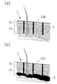
- the needle 33b penetrates into the epidermal layer 1a and the dermal layer 1b of the skin 1 as shown in FIG. 12A.
- the skin 1 of the human body is largely divided into the epidermal layer 1a and the dermal layer 1b, but slightly different for each position.
- the epidermal layer 1a is about 0.25 mm thick and the dermal layer 1b is about 0.35 mm thick. . That is, even if the needle 33b penetrates to the dermal layer 1b of the skin 1, no pain can be felt at all, and only a feeling of contacting causes no burden on use. Since the skin 1 is generally affected by the material present in the dermal layer 1b, it is preferable that the needle 33b penetrates through the epidermal layer 1a to the place where the dermal layer 1b is located.
- the solution 2 of the receiving unit 10 is discharged from the needle 33b and injected into the dermal layer 1b secondaryly as shown in FIG. 12B. That is, the solution 2 is injected into the desired skin 1 as shown in FIG. 10, but depending on the volume of the accommodating part 10, the use is completed in about 20 to 50 times.
- the solution 2 having a predetermined effect in the skin 1 is injected in the state in which the needle 33b is directly infiltrated, and thus has a water absorption of 90 to 99%, thereby achieving a more reliable and excellent effect.
- the excellent absorption rate the effect is excellent even with a small solution (2), thereby minimizing the consumer's cost burden.
- the device of the present invention is used, but may be separated and discharged (disposal) by recycling, but after dividing both the receiving portion 10, the pumping portion 20 and the injection portion 30 soaked in alcohol or disinfected with ultraviolet rays and If dried, the solution 2 may be replenished in the container 10 and reused.
- Handle portion 10 is provided to protrude so that the user can hold, and has a coupling protrusion 11 having one or more stepped on the bottom.
- Handle portion 10 is to discharge the solution (2) having excellent efficacy for skin improvement and skin beauty as shown in Figure 7 to induce the injection into the skin (1), protrudes to a predetermined length so that the user can grip by hand And it is provided with a coupling projection (11) at the bottom.
- Coupling projection 11 is engaged to engage with the packing portion 20 to be described later as shown in FIG.
- the coupling protrusion 11 is preferably formed to have at least one step because the coupling protrusion 11 should be able to be detached as necessary while being engaged with the packing part 20. That is, the coupling protrusion 11 may be formed in various structures within the range not to be separated in the state in which the packing part 20 is coupled in addition to the illustrated.
- the handle portion 10 is provided with a rubber grip 15 or concave-convex 16 on the outer peripheral surface to prevent the slip while improving the grip feeling from the user.
- the handle part 10 injects the solution 2 into the skin 1 in conjunction with the packing part 20 and the injection part 30 which will be described later.
- the rubber grip 15 or the concave-convex 16 is provided on the outer circumferential surface to facilitate the pressure movement on the c).
- the rubber grip 15 further includes a soft rubber material attached to the outer circumferential surface as shown in FIG. 9A, and guides the user to grip smoothly with a predetermined cushion and prevents slippage.
- the rubber grip 15 may form an emboss of a vertical, horizontal, or lattice type in addition to the illustrated one, and may be formed of an overall curved surface.
- Concave-convex 16 is formed integrally with the user's finger engaging protrusions on the outer circumferential surface, as shown in Figure 9b, to guide the user to safely grip without burden to the user when gripping and prevent slipping.
- These unevenness 16 may be formed in the form of a fine V groove in the form of X in addition to the overall curved surface.
- the rubber grip 15 and the concave-convex 16 can be formed independently, but can be formed in parallel to prevent more improved grip and slip.
- those skilled in the art can form and further attach in various shapes and shapes within the range to prevent grip and slipping.
- the packing portion 20 is provided detachably at the lower portion of the handle portion 10, and has a coupling groove 21 which is engaged with the coupling projection 11 is fixed.
- the packing part 20 generates a predetermined pressure to inject the solution 2 into the skin 1 by interlocking with the handle part 10 as shown in FIG. 7. It is possible to provide. That is, the packing part 20 is formed of a rubber material as a whole, and sealed so that the solution 2 is accommodated in the injection part 30 to be described later, while receiving a pressurization movement of the handle part 10 to pressurize the solution 2. To be discharged (injected) to the outside.
- the packing part 20 is formed of a material having excellent sealing force, and is preferably formed of a material that is harmless to the human body and is not affected by the components of the solution 2.
- the injection portion 30 according to the present invention is coupled to the sealing portion in engagement with the packing portion 20, and discharges the solution (2) by the pressure movement of the handle portion 10 to penetrate into the skin (1).
- the injection part 30 discharges the solution 2 by the pressure movement of the handle part 10 and penetrates it into the skin 1 as shown in FIGS. 7 and 8, and accommodates the packing part 20 while accommodating the solution 2. It is provided to interlock.
- the injection portion 30 is coupled to the packing portion 20, the housing 31 having a fixture (31a) and the inclined sphere (31b) and the space (31d) for accommodating the solution (2) And a needle portion 33 having a needle groove 33a and a needle 33b at the lower portion of the housing 31, and a fixing groove 35a to fix the housing 31 and the needle portion 33. It consists of a fixing part 35 provided with a fixing protrusion 35b.
- Injection portion 30 is the same as the injection portion 30 according to the first embodiment described above as shown in FIG. 8 operation and detailed description thereof will be omitted.
- the space (not shown) of the housing 31 according to the first embodiment is for vertical movement in conjunction with the pumping unit 20, and the space 31d of the housing 31 according to the second embodiment.
- the handle part 10 coupled to the packing part 20 is inserted as shown in FIG. 11, and the user grips the handle part 10.
- the needle 23b penetrates into the skin 1 and the solution 2 is discharged and injected at a predetermined pressure.
- the present invention can reduce the manufacturing cost by forming a stamp-type light and simple structure, and can be easily and conveniently used at home at a low price, and the solution directly in the state where the needle penetrates into the epidermal and dermal layers of the skin.
- uniformly injecting has the effect of maximizing efficacy while minimizing loss of solution.
Landscapes
- Health & Medical Sciences (AREA)
- Engineering & Computer Science (AREA)
- Animal Behavior & Ethology (AREA)
- General Health & Medical Sciences (AREA)
- Biomedical Technology (AREA)
- Heart & Thoracic Surgery (AREA)
- Hematology (AREA)
- Life Sciences & Earth Sciences (AREA)
- Veterinary Medicine (AREA)
- Anesthesiology (AREA)
- Public Health (AREA)
- Vascular Medicine (AREA)
- Dermatology (AREA)
- Medical Informatics (AREA)
- Infusion, Injection, And Reservoir Apparatuses (AREA)
- Massaging Devices (AREA)
Description
Claims (12)
- 피부(1)내에 소정의 효능을 지닌 용액(2)을 침투시켜 피부개선 또는 미용을 위한 자가(self) 주입기구에 있어서:내부에 용액(2)을 수용하도록 공간(11)을 구비하고, 일단에 공기만을 흡입하는 흡입구(12)와 타단에 용액(2)이 배출되게 개방된 배출구(15)를 구비하는 수용부(10);상기 수용부(10)의 배출구(15)와 연통되게 결합되고, 중앙에 상하운동으로 용액(2)을 토출하는 에어리스펌프(21)를 구비하는 펌핑부(20); 및상기 펌핑부(20)의 에어리스펌프(21)와 연통되게 결합되고, 상하운동으로 토출된 용액(2)을 피부(1)내에 침투시키는 주입부(30);를 포함하여 이루어지는 것을 특징으로 하는 피부용 자가 주입기구.
- 제1항에 있어서,상기 수용부(10)는 흡입구(12)의 용액(2)을 밀폐하면서 공간(11)상에서 유동하는 패킹(13)과 함께 흡입공(14a)을 개재한 커버(14)를 구비하는 것을 특징으로 하는 피부용 자가 주입기구.
- 제1항에 있어서,상기 주입부(30)는 에어리스펌프(21)와 결합되는 고정구(31a)와 경사구(31b)를 구비하는 하우징(31)과, 상기 하우징(31)의 하부에 니들홈(33a)과 니들(33b)을 구비하는 니들부(33)와, 상기 하우징(31)과 니들부(33)를 고정되게 고정홈(35a)과 고정돌부(35b)를 구비하는 고정부(35)로 이루어진 것을 특징으로 하는 피부용 자가 주입기구.
- 제1항에 있어서,상기 하우징(31)은 외주면에 사용자로부터 그립감을 향상하면서 미끄러짐을 방지하도록 고무그립(32a) 또는 요철(32b)을 더 구비하는 것을 특징으로 하는 피부용 자가 주입기구.
- 제1항에 있어서,상기 하우징(31)은 상부 내주면에 펌핑부(20)로부터 회전을 방지하도록 하나 이상의 고정돌부(32c)와 슬라이드홈(32d)을 더 구비하는 것을 특징으로 하는 피부용 자가 주입기구.
- 피부(1)내에 소정의 효능을 지닌 용액(2)을 침투시켜 피부개선 또는 미용을 위한 자가(self) 주입기구에 있어서:사용자가 파지할 수 있도록 돌출되게 구비하고, 하부에 하나 이상의 단턱을 지닌 결합돌기(11)를 구비하는 손잡이부(10);상기 손잡이부(10)의 하부에 탈부착 가능하게 구비하고, 상기 결합돌기(11)와 맞물려 고정되는 결합홈(21)을 구비하는 패킹부(20); 및상기 패킹부(20)와 맞물려 밀폐되게 결합되고, 상기 손잡이부(10)의 가압운동으로 용액(2)을 토출시켜 피부(1)내에 침투시키는 주입부(30);를 포함하여 이루어지는 것을 특징으로 하는 피부용 자가 주입기구.
- 제6항에 있어서,상기 손잡이부(10)는 외주면에 사용자로부터 그립감을 향상하면서 미끄러짐을 방지하도록 고무그립(15) 또는 요철(16)을 구비하는 것을 특징으로 하는 피부용 자가 주입기구.
- 제6항에 있어서,상기 주입부(30)는 패킹부(20)와 결합되면서 용액(2)을 수용하는 고정구(31a)와 경사구(31b) 및 공간(31d)을 구비하는 하우징(31)과, 상기 하우징(31)의 하부에 니들홈(33a)과 니들(33b)을 구비하는 니들부(33)와, 상기 하우징(31)과 니들부(33)를 고정되게 고정홈(35a)과 고정돌부(35b)를 구비하는 고정부(35)로 이루어진 것을 특징으로 하는 피부용 자가 주입기구.
- 제3항 또는 청구항 6항의 어느 한 항에 있어서,상기 니들부(33)의 니들홈(33a)은 니들(33b)을 삽입 고정하는 고정홈(34a)과, 상기 고정홈(34a)의 상부로 니들(33b)이 중앙으로 안전하게 유도하는 유도홈(34b)을 구비하는 것을 특징으로 하는 피부용 자가 주입기구.
- 제3항 또는 청구항 6항의 어느 한 항에 있어서,상기 니들부(33)는 피부(1)내에 침투되도록 소정의 길이로 돌출된 다수의 니들(33b)을 구비하되, 이들 중에서 어느 하나 이상을 피부(1)의 표면에 접촉되도록 비돌출된 니들(33c)을 더 구비하는 것을 특징으로 하는 피부용 자가 주입기구.
- 제3항 또는 청구항 6항의 어느 한 항에 있어서,상기 고정부(35)는 하우징(31)의 경사구(31b)상에 니들(33b)을 고정함과 함께 공간을 차단시켜 용액의 낭비를 최소화도록 경화제(36)를 더 충진하는 것을 특징으로 하는 피부용 자가 주입기구.
- 제3항 또는 청구항 6항의 어느 한 항에 있어서,상기 하우징(31)은 니들부(33)를 보호하면서 세균이나 이물질의 유입을 차단하도록 결합되는 걸림돌기(37a)를 개재한 안전캡(37)을 더 구비하는 것을 특징으로 하는 피부용 자가 주입기구.
Priority Applications (6)
| Application Number | Priority Date | Filing Date | Title |
|---|---|---|---|
| JP2015517163A JP2015519968A (ja) | 2012-06-12 | 2013-01-24 | 肌用自己注入器具 |
| CA2886670A CA2886670A1 (en) | 2012-06-12 | 2013-01-24 | Self-injection mechanism for use on skin |
| BR112014031242A BR112014031242A2 (pt) | 2012-06-12 | 2013-01-24 | mecanismo de auto-injeção para uso na pele que é configurado para injetar uma solução tendo uma eficácia predeterminada na pele para melhorias na pele ou tratamento de beleza |
| EP13803520.9A EP2859909A4 (en) | 2012-06-12 | 2013-01-24 | SELF-INJECTION MECHANISM FOR USE ON THE SKIN |
| US14/407,239 US20150126937A1 (en) | 2012-06-12 | 2013-01-24 | Self-injection mechanism for use on skin |
| CN201380031092.3A CN104470577B (zh) | 2012-06-12 | 2013-01-24 | 皮肤用自助注入仪器 |
Applications Claiming Priority (4)
| Application Number | Priority Date | Filing Date | Title |
|---|---|---|---|
| KR20120062714 | 2012-06-12 | ||
| KR10-2012-0062714 | 2012-06-12 | ||
| KR10-2012-0132763 | 2012-11-22 | ||
| KR1020120132763A KR101494616B1 (ko) | 2012-06-12 | 2012-11-22 | 피부용 자가 주입기구 |
Publications (1)
| Publication Number | Publication Date |
|---|---|
| WO2013187572A1 true WO2013187572A1 (ko) | 2013-12-19 |
Family
ID=49984551
Family Applications (1)
| Application Number | Title | Priority Date | Filing Date |
|---|---|---|---|
| PCT/KR2013/000561 Ceased WO2013187572A1 (ko) | 2012-06-12 | 2013-01-24 | 피부용 자가 주입기구 |
Country Status (8)
| Country | Link |
|---|---|
| US (1) | US20150126937A1 (ko) |
| EP (1) | EP2859909A4 (ko) |
| JP (1) | JP2015519968A (ko) |
| KR (1) | KR101494616B1 (ko) |
| CN (1) | CN104470577B (ko) |
| BR (1) | BR112014031242A2 (ko) |
| CA (1) | CA2886670A1 (ko) |
| WO (1) | WO2013187572A1 (ko) |
Families Citing this family (11)
| Publication number | Priority date | Publication date | Assignee | Title |
|---|---|---|---|---|
| US11116302B2 (en) * | 2015-06-11 | 2021-09-14 | The Procter & Gamble Company | Apparatus and methods for modifying keratinous surfaces |
| CN105413024A (zh) * | 2016-01-07 | 2016-03-23 | 深圳市赫拉铂氢时代科技有限公司 | 纳米/微米氢水无针注射仪及其注射方法 |
| WO2017142379A2 (ko) * | 2016-02-18 | 2017-08-24 | 주식회사 다오닉 | 피부미용장치의 핸드피스 |
| KR101695603B1 (ko) * | 2016-11-08 | 2017-01-12 | 이창우 | 병목 하단 밀착 구조의 점탄성 연결캡을 포함하는 니들 디스크 롤러 장치 |
| KR101897958B1 (ko) * | 2016-11-18 | 2018-09-13 | 주식회사 피코바이오 | 피부 자극을 위한 미용기 |
| KR101758041B1 (ko) * | 2017-03-24 | 2017-07-14 | 이창우 | 니들플레이트 스탬프 |
| FR3070013B1 (fr) * | 2017-08-08 | 2019-11-15 | Isabelle Grozelier | Dispositif d'incision superficielle, notamment pour diagnostic allergique |
| KR101906336B1 (ko) * | 2018-03-22 | 2018-10-10 | 한국바이오기술공사(주) | 펌프 내장형 니들 디스크 롤러 장치 |
| KR20210136748A (ko) | 2020-05-08 | 2021-11-17 | 주식회사 솔텍엔지니어링 | 피부용 자가 주입기구 |
| KR102501483B1 (ko) * | 2020-05-28 | 2023-02-21 | 장건주 | 멀티니들이 구비된 자동충진 주사 장치 |
| US20250295215A1 (en) * | 2024-03-22 | 2025-09-25 | Elc Management Llc. | Manual Applicator For Cosmetic Product |
Citations (8)
| Publication number | Priority date | Publication date | Assignee | Title |
|---|---|---|---|---|
| US20020076256A1 (en) * | 1999-04-16 | 2002-06-20 | L'oreal Of Paris, France | Applicator and applicator assembly equipped with such an applicator |
| KR200395359Y1 (ko) | 2005-06-27 | 2005-09-08 | (주)클리니칼레졸루션아시아 | 마이크로니들 롤러 |
| KR200423963Y1 (ko) | 2006-03-27 | 2006-08-14 | 주식회사 토아스 | 스탬프형 피부 자극기 |
| JP2007532245A (ja) * | 2004-04-12 | 2007-11-15 | アラーガン、インコーポレイテッド | マルチサイト注射システム |
| KR20100064669A (ko) * | 2008-12-05 | 2010-06-15 | 폴 곽 | 마이크로 니들 피부 미용기 |
| KR20110098398A (ko) * | 2010-02-26 | 2011-09-01 | 주식회사 유니온 메디칼 | 주입식 마이크로니들 스탬프 |
| KR20110108445A (ko) | 2010-03-29 | 2011-10-06 | 이충열 | 여드름, 각종 흉터 및 주름치료를 돕는 자동 피부 마이크로-채널 스탬프 |
| KR101200669B1 (ko) * | 2012-03-29 | 2012-11-12 | 장지영 | 피부용 자가 주입기구 |
Family Cites Families (9)
| Publication number | Priority date | Publication date | Assignee | Title |
|---|---|---|---|---|
| JPH0592037A (ja) * | 1990-09-14 | 1993-04-16 | Mentor Corp | 医療用パスタ注射器及び充填方法 |
| US5527288A (en) * | 1990-12-13 | 1996-06-18 | Elan Medical Technologies Limited | Intradermal drug delivery device and method for intradermal delivery of drugs |
| DE9107574U1 (de) * | 1991-06-20 | 1991-08-01 | Heraeus Kulzer GmbH & Co. KG, 63450 Hanau | Spritzenartige Vorrichtung zum Dosieren von Flüssigkeiten oder Pasten |
| FR2788501B1 (fr) * | 1999-01-15 | 2001-03-02 | Oreal | Ensemble de conditionnement et d'application avec applicateur a chargement automatique |
| JP2003290350A (ja) * | 2002-04-05 | 2003-10-14 | Asahi Kasei Corp | 薬液封入方法 |
| KR100902133B1 (ko) * | 2008-01-14 | 2009-06-10 | 최종수 | 멀티 니들 |
| US8409147B2 (en) * | 2009-08-22 | 2013-04-02 | Joseph Wayne Kraft | Rapid local anesthesia linear injection device |
| KR200458000Y1 (ko) * | 2010-01-07 | 2012-01-16 | (주)아모레퍼시픽 | 잔량확인이 가능한 에어리스펌프를 갖는 화장품용기 |
| KR20120044612A (ko) * | 2010-10-28 | 2012-05-08 | (주)엠툴즈 | 피부 시술용 모듈 |
-
2012
- 2012-11-22 KR KR1020120132763A patent/KR101494616B1/ko active Active
-
2013
- 2013-01-24 US US14/407,239 patent/US20150126937A1/en not_active Abandoned
- 2013-01-24 CA CA2886670A patent/CA2886670A1/en not_active Abandoned
- 2013-01-24 WO PCT/KR2013/000561 patent/WO2013187572A1/ko not_active Ceased
- 2013-01-24 EP EP13803520.9A patent/EP2859909A4/en not_active Withdrawn
- 2013-01-24 BR BR112014031242A patent/BR112014031242A2/pt not_active IP Right Cessation
- 2013-01-24 CN CN201380031092.3A patent/CN104470577B/zh not_active Expired - Fee Related
- 2013-01-24 JP JP2015517163A patent/JP2015519968A/ja active Pending
Patent Citations (8)
| Publication number | Priority date | Publication date | Assignee | Title |
|---|---|---|---|---|
| US20020076256A1 (en) * | 1999-04-16 | 2002-06-20 | L'oreal Of Paris, France | Applicator and applicator assembly equipped with such an applicator |
| JP2007532245A (ja) * | 2004-04-12 | 2007-11-15 | アラーガン、インコーポレイテッド | マルチサイト注射システム |
| KR200395359Y1 (ko) | 2005-06-27 | 2005-09-08 | (주)클리니칼레졸루션아시아 | 마이크로니들 롤러 |
| KR200423963Y1 (ko) | 2006-03-27 | 2006-08-14 | 주식회사 토아스 | 스탬프형 피부 자극기 |
| KR20100064669A (ko) * | 2008-12-05 | 2010-06-15 | 폴 곽 | 마이크로 니들 피부 미용기 |
| KR20110098398A (ko) * | 2010-02-26 | 2011-09-01 | 주식회사 유니온 메디칼 | 주입식 마이크로니들 스탬프 |
| KR20110108445A (ko) | 2010-03-29 | 2011-10-06 | 이충열 | 여드름, 각종 흉터 및 주름치료를 돕는 자동 피부 마이크로-채널 스탬프 |
| KR101200669B1 (ko) * | 2012-03-29 | 2012-11-12 | 장지영 | 피부용 자가 주입기구 |
Non-Patent Citations (1)
| Title |
|---|
| See also references of EP2859909A4 * |
Also Published As
| Publication number | Publication date |
|---|---|
| BR112014031242A2 (pt) | 2017-06-27 |
| CN104470577A (zh) | 2015-03-25 |
| JP2015519968A (ja) | 2015-07-16 |
| EP2859909A4 (en) | 2016-07-06 |
| EP2859909A1 (en) | 2015-04-15 |
| KR101494616B1 (ko) | 2015-03-04 |
| CA2886670A1 (en) | 2013-12-19 |
| US20150126937A1 (en) | 2015-05-07 |
| CN104470577B (zh) | 2017-03-15 |
| KR20130139149A (ko) | 2013-12-20 |
Similar Documents
| Publication | Publication Date | Title |
|---|---|---|
| WO2013187572A1 (ko) | 피부용 자가 주입기구 | |
| KR101200669B1 (ko) | 피부용 자가 주입기구 | |
| US11806495B2 (en) | Devices and methods for treating the skin | |
| US11744999B2 (en) | Devices and methods for treating the skin | |
| WO2019182281A1 (ko) | 펌프 내장형 디스크 롤러장치 | |
| EP3154623A1 (en) | Applicator and cartridge for such applicator | |
| WO2018101599A1 (ko) | 피부용 수동식 인젝터기 | |
| KR101782267B1 (ko) | 분무기 기능이 구비된 두피 치료용 머리빗 | |
| KR101670271B1 (ko) | 약액 주입이 향상된 미용 마스크 | |
| KR101596419B1 (ko) | 약물분배체가 구비된 피부시술용 멀티 니들장치 | |
| KR20200125230A (ko) | 약물 펌핑수단을 갖는 피부 관리장치 | |
| KR101922242B1 (ko) | 부스형 전신 스프레이 장치 | |
| KR20200100264A (ko) | 약물 펌핑수단을 갖는 피부 관리장치 | |
| KR20210051126A (ko) | 승하강 동력전달수단을 갖는 피부 관리용 약물도포장치 | |
| US20090092438A1 (en) | Applicator, use of the applicator and method for topically administering a liquid by means of the applicator | |
| KR102605068B1 (ko) | 피부 마사지기 | |
| KR20210051128A (ko) | 약물 펌핑수단을 갖는 피부 관리장치 | |
| KR20210008279A (ko) | 피부 관리용 약물도포장치 | |
| RU2188617C2 (ru) | Лечебно-массажная расческа | |
| IT202400000960A1 (it) | Pettine per erogare una sostanza liquida sul cuoio capelluto o sui capelli | |
| CA2971728C (en) | Devices for treating the skin using a rollerball | |
| CN104922792A (zh) | 一种涂药按摩仪 | |
| CN2383514Y (zh) | 白癜风愈油治疗器 |
Legal Events
| Date | Code | Title | Description |
|---|---|---|---|
| 121 | Ep: the epo has been informed by wipo that ep was designated in this application |
Ref document number: 13803520 Country of ref document: EP Kind code of ref document: A1 |
|
| ENP | Entry into the national phase |
Ref document number: 2886670 Country of ref document: CA |
|
| WWE | Wipo information: entry into national phase |
Ref document number: 14407239 Country of ref document: US |
|
| ENP | Entry into the national phase |
Ref document number: 2015517163 Country of ref document: JP Kind code of ref document: A |
|
| NENP | Non-entry into the national phase |
Ref country code: DE |
|
| WWE | Wipo information: entry into national phase |
Ref document number: 2013803520 Country of ref document: EP |
|
| REG | Reference to national code |
Ref country code: BR Ref legal event code: B01A Ref document number: 112014031242 Country of ref document: BR |
|
| ENP | Entry into the national phase |
Ref document number: 112014031242 Country of ref document: BR Kind code of ref document: A2 Effective date: 20141212 |