WO2013190746A1 - アーク溶接方法およびアーク溶接装置 - Google Patents
アーク溶接方法およびアーク溶接装置 Download PDFInfo
- Publication number
- WO2013190746A1 WO2013190746A1 PCT/JP2013/001550 JP2013001550W WO2013190746A1 WO 2013190746 A1 WO2013190746 A1 WO 2013190746A1 JP 2013001550 W JP2013001550 W JP 2013001550W WO 2013190746 A1 WO2013190746 A1 WO 2013190746A1
- Authority
- WO
- WIPO (PCT)
- Prior art keywords
- arc
- welding
- short
- current
- state
- Prior art date
- Legal status (The legal status is an assumption and is not a legal conclusion. Google has not performed a legal analysis and makes no representation as to the accuracy of the status listed.)
- Ceased
Links
Images




Classifications
-
- B—PERFORMING OPERATIONS; TRANSPORTING
- B23—MACHINE TOOLS; METAL-WORKING NOT OTHERWISE PROVIDED FOR
- B23K—SOLDERING OR UNSOLDERING; WELDING; CLADDING OR PLATING BY SOLDERING OR WELDING; CUTTING BY APPLYING HEAT LOCALLY, e.g. FLAME CUTTING; WORKING BY LASER BEAM
- B23K9/00—Arc welding or cutting
- B23K9/06—Arrangements or circuits for starting the arc, e.g. by generating ignition voltage, or for stabilising the arc
- B23K9/073—Stabilising the arc
- B23K9/0732—Stabilising of the arc current
-
- B—PERFORMING OPERATIONS; TRANSPORTING
- B23—MACHINE TOOLS; METAL-WORKING NOT OTHERWISE PROVIDED FOR
- B23K—SOLDERING OR UNSOLDERING; WELDING; CLADDING OR PLATING BY SOLDERING OR WELDING; CUTTING BY APPLYING HEAT LOCALLY, e.g. FLAME CUTTING; WORKING BY LASER BEAM
- B23K9/00—Arc welding or cutting
- B23K9/095—Monitoring or automatic control of welding parameters
-
- B—PERFORMING OPERATIONS; TRANSPORTING
- B23—MACHINE TOOLS; METAL-WORKING NOT OTHERWISE PROVIDED FOR
- B23K—SOLDERING OR UNSOLDERING; WELDING; CLADDING OR PLATING BY SOLDERING OR WELDING; CUTTING BY APPLYING HEAT LOCALLY, e.g. FLAME CUTTING; WORKING BY LASER BEAM
- B23K9/00—Arc welding or cutting
- B23K9/06—Arrangements or circuits for starting the arc, e.g. by generating ignition voltage, or for stabilising the arc
- B23K9/073—Stabilising the arc
-
- B—PERFORMING OPERATIONS; TRANSPORTING
- B23—MACHINE TOOLS; METAL-WORKING NOT OTHERWISE PROVIDED FOR
- B23K—SOLDERING OR UNSOLDERING; WELDING; CLADDING OR PLATING BY SOLDERING OR WELDING; CUTTING BY APPLYING HEAT LOCALLY, e.g. FLAME CUTTING; WORKING BY LASER BEAM
- B23K9/00—Arc welding or cutting
- B23K9/09—Arrangements or circuits for arc welding with pulsed current or voltage
-
- B—PERFORMING OPERATIONS; TRANSPORTING
- B23—MACHINE TOOLS; METAL-WORKING NOT OTHERWISE PROVIDED FOR
- B23K—SOLDERING OR UNSOLDERING; WELDING; CLADDING OR PLATING BY SOLDERING OR WELDING; CUTTING BY APPLYING HEAT LOCALLY, e.g. FLAME CUTTING; WORKING BY LASER BEAM
- B23K9/00—Arc welding or cutting
- B23K9/09—Arrangements or circuits for arc welding with pulsed current or voltage
- B23K9/091—Arrangements or circuits for arc welding with pulsed current or voltage characterised by the circuits
- B23K9/092—Arrangements or circuits for arc welding with pulsed current or voltage characterised by the circuits characterised by the shape of the pulses produced
-
- B—PERFORMING OPERATIONS; TRANSPORTING
- B23—MACHINE TOOLS; METAL-WORKING NOT OTHERWISE PROVIDED FOR
- B23K—SOLDERING OR UNSOLDERING; WELDING; CLADDING OR PLATING BY SOLDERING OR WELDING; CUTTING BY APPLYING HEAT LOCALLY, e.g. FLAME CUTTING; WORKING BY LASER BEAM
- B23K9/00—Arc welding or cutting
- B23K9/12—Automatic feeding or moving of electrodes or work for spot or seam welding or cutting
- B23K9/124—Circuits or methods for feeding welding wire
Definitions
- the present invention relates to an arc welding method and an arc welding apparatus for performing welding by alternately generating a short circuit state and an arc state while repeating normal feeding and reverse feeding as feeding of a welding wire as a consumable electrode.
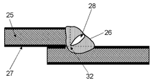
- FIG. 8 shows a bead cross section when a galvanized steel sheet is constructed by a general consumable electrode arc welding method as a welding method.
- the zinc boiling point of the zinc plating 27 plated on the surface of the workpiece 25 shown in FIG. 8 is 907 degrees, which is lower than the melting point of iron, 1536 degrees.
- arc welding is performed on a galvanized steel sheet, zinc is vaporized, and this vapor zinc attempts to diffuse through the molten pool to the outside.
- the solidification rate of the molten metal that is the workpiece 25 is high, the vapor zinc cannot be sufficiently released to the outside of the molten pool, and remains as pores 28 in the weld bead 26 or on the surface of the weld bead 26.
- the pore 28 stays inside the weld bead 26, it becomes a blow hole.
- FIGS. 11A and 11B show the welding current and wire feed when pulse welding is performed using Ar or a gas in which carbon dioxide is mixed in Ar at a ratio of 25% or less.
- the waveform of the feeding speed is shown.
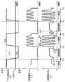
- FIG. 11A shows the waveform of the welding current
- FIG. 11B shows the waveform of the wire feed speed.
- the waveform of the welding current has a first period TL and a second period TH.
- the sum of the first period TL and the second period TH is the swell frequency divider TW.
- the undulation cycle TW is a cycle of the number of cycles repeated per second.
- An arc welding method is known in which the current waveform pattern or the wire feed speed is varied at a frequency of 10 to 50 Hz in the undulation cycle TW (see, for example, Patent Document 1).
- the first period TL is a period having a current waveform in which the first average arc force FL acts on the molten pool.
- the second period TH is a period having a current waveform in which the second average arc force FH, which is an arc force larger than the first average arc force FL, acts on the molten pool.
- the arc force acts as a force that pushes down the molten pool. Therefore, when the arc force fluctuates between the first average arc force FL and the second average arc force FH, the molten pool becomes in a wavy state. Even if pores 28 are generated from the galvanized layer in the molten pool due to this undulating state, the pores 28 reach the surface of the molten pool due to the flow of the molten pool and the buoyancy of the pores 28 and are released to the outside of the molten pool. .
- the molten metal ejected when the vapor zinc is released is directly scattered outside as spatter.
- An arc welding method of the present invention is an arc welding method in welding in which a short circuit and an arc are repeated.
- a sign of opening of a short circuit is detected, a second current value lower than the first current value at the time of detecting the sign is detected.
- the welding current is reduced so that When the opening of the short circuit is detected, a pulse current having a peak value larger than the first current value is supplied a plurality of times during the arc period.
- the lower limit value of the pulse current supplied a plurality of times during the arc period is lower than the first current value.
- the lower limit value of the pulse current supplied a plurality of times during the arc period is lower than the second current value.
- the arc welding method of the present invention is an arc welding method in welding that repeats short-circuiting and arcing, and when a short-circuit opening is detected, a plurality of pulse currents having a peak value larger than the current value at the time of short-circuit opening are detected during the arc period. Supply once.
- the lower limit value of the pulse current supplied a plurality of times during the arc period is lower than the current value when the short circuit is opened.
- the arc welding method of the present invention feeds the wire at a wire feeding speed that repeats forward feeding and reverse feeding.
- the arc welding method of the present invention periodically repeats forward and reverse feeding of the wire feed speed with a predetermined cycle and a predetermined amplitude.
- the arc welding method of the present invention in addition to the above, repeats the forward feed and reverse feed of the wire feed speed is not periodic, and performs reverse feed when detecting that the welding state is a short-circuited state, When it is detected that the welding state is an arc state, forward feeding is performed.
- the arc welding apparatus of the present invention is an arc welding apparatus that performs welding by repeating short-circuiting and arcing, and includes a primary rectification unit, a switching unit, a transformer, a secondary rectification unit, a drive unit, and welding.
- the primary rectification unit rectifies the input power
- the switching unit converts the output of the primary rectification unit into alternating current.
- the transformer transforms the output of the switching unit, and the secondary rectification unit rectifies the output of the transformer.
- the drive unit controls the switching unit, and the welding voltage detection unit detects the welding voltage.
- the short circuit / arc detection unit determines whether the welding state is a short circuit state or an arc state based on the output of the welding voltage detection unit, and changes from the short circuit state to the arc state based on the output of the welding voltage detection unit. And a function of detecting a predictor.
- the short-circuit control unit controls the welding output in the short-circuit state, and the arc control unit controls the welding output in the arc state.
- the welding current is reduced so that the second current value is lower than the first current value when the sign is detected.
- a pulse current having a peak value larger than the first current value is supplied a plurality of times during the arc period.
- the arc welding apparatus of the present invention is an arc welding apparatus that performs welding by repeating short-circuiting and arcing, and includes a primary rectification unit, a switching unit, a transformer, a secondary rectification unit, a drive unit, and welding.
- the primary rectification unit rectifies the input power
- the switching unit converts the output of the primary rectification unit into alternating current.
- the transformer transforms the output of the switching unit, and the secondary rectifier rectifies the output of the transformer.
- the drive unit controls the switching unit, and the welding voltage detection unit detects the welding voltage.
- the short circuit / arc detection unit determines whether the welding state is a short circuit state or an arc state based on the output of the welding voltage detection unit.
- the short-circuit control unit controls the welding output in the short-circuit state, and the arc control unit controls the welding output in the arc state.
- a pulse current having a peak value larger than the current value when the short-circuit is opened is supplied a plurality of times during the arc period.
- the arc welding apparatus of the present invention further includes a wire feeding speed control unit that controls feeding of the welding wire, and feeds the welding wire at a wire feeding speed that repeats forward feeding and reverse feeding. Make a salary.
- the molten pool is pushed so that the overlapping portion of the member is exposed.
- the gas generated from the member escapes from the exposed root portion, generation of pores such as blow holes and generation of spatter can be suppressed.
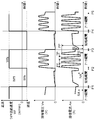
- FIG. 1 is a diagram showing waveforms of wire feed speed (sinusoidal), welding voltage, and welding current in the embodiment of the present invention.
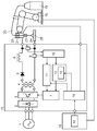
- FIG. 2 is a diagram showing a schematic configuration of the arc welding apparatus in the embodiment of the present invention.
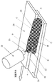
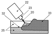
- FIG. 3 is a diagram showing a state in which welding is performed by the arc welding method according to the embodiment of the present invention.
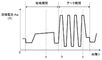
- FIG. 4 is a diagram showing a welding current waveform in the embodiment of the present invention.
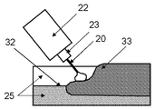
- FIG. 5A is a cross-sectional view of a short circuit state according to the embodiment of the present invention.
- FIG. 5B is a cross-sectional view showing a state in which the first pulse after the short circuit is opened in the embodiment of the present invention.
- FIG. 5C is a cross-sectional view showing a state in which the fourth pulse after the short-circuit opening in the embodiment of the present invention is applied.
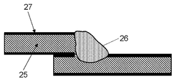
- FIG. 6 is a diagram showing a cross section of the welded portion in the embodiment of the present invention.
- FIG. 7 is a diagram showing a cross section of the welded portion in the embodiment of the present invention.
- FIG. 8 is a view showing a cross section of a welded portion when a galvanized steel sheet is welded by a conventional arc welding control method.
- FIG. 9 is a diagram showing waveforms of the wire feed speed (trapezoidal wave shape), the welding voltage, and the welding current in the embodiment of the present invention.
- FIG. 10 is a diagram showing waveforms of the wire feed speed, the welding voltage, and the welding current in the embodiment of the present invention.
- FIG. 11A is a diagram showing a waveform of a welding current in a conventional arc welding method.
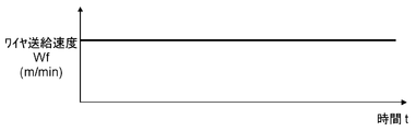
- FIG. 11B is a diagram showing a waveform of the wire feed speed in the conventional arc welding control method.
- FIG. 1 is a diagram showing a waveform of a change over time in wire feed speed, welding voltage, and welding current in consumable electrode type arc welding in which a short circuit state and an arc state are alternately repeated.
- wire feed control having a predetermined frequency and a predetermined speed amplitude is performed with a predetermined wire feed speed Wf1 as a reference.
- wire feed control is performed in which forward feed and reverse feed are periodically repeated. That is, regardless of whether the welding state is a short-circuit state or an arc state, the forward feed and the reverse feed are periodically repeated with a sine wave basic waveform.
- a short circuit occurs around the time point P1
- an arc occurs around the time point P2.
- the next short circuit occurs in the vicinity of the time point P3, which is the peak of forward feeding after the time point P2.
- Short circuiting is promoted when the wire feed speed Wf is forward feeding, and opening is promoted when the wire feeding speed Wf is reverse feeding.
- the occurrence of the short circuit state or the arc state basically depends on the wire feed control in which the forward feed and the reverse feed of the wire feed speed are periodically repeated.
- the time P1 indicates the time when the short circuit is started, and the short-circuit initial current SA is output for a predetermined time from the time P1. Thereafter, the short-circuit current is increased as an increase slope di / dt (increase in current per unit time) of the first stage of the short-circuit current. Subsequently, the second stage increase slope di / dt (increase in current per unit time) of the short-circuit current whose slope is gentler than the first stage increase slope di / dt (increase in current per unit time). Increase the short circuit current as quantity).
- the constriction of the droplet formed between the molten pool formed in the welding object and the tip of the welding wire as the short circuit opens is detected.
- the welding current is lower than the current IA (first current value) when the constriction is detected in order to suppress spattering when the short circuit is opened.
- the current NA (second current value) is instantaneously reduced.
- Time P2 indicates a point in time when the constriction of the droplets is released, the short circuit is opened, the short circuit state is finished, and the arc state is generated.
- the welding current of the peak current PP is output during the peak current period TP immediately after the short circuit is opened, that is, immediately after the occurrence of the arc. Thereafter, the welding current shifts from the peak current PP to the base current PB, and the base current PB is output during the base current period TB.
- the change between the peak current PP and the base current PB is controlled by a predetermined slope di / dt (current change amount per unit time), or a rise time and a fall time, and a predetermined pulse frequency.
- a predetermined number of pulses is output at (pulse period PF). Then, the next short circuit is waited in a state where the welding current is controlled to the short circuit waiting current IB.
- FIG. 1 shows an example in which the number of pulses is four.
- the peak current PP is larger than the current IA and the constriction current NA when the constriction is detected.
- the base current PB is smaller than the current IA and the constriction current NA at the time when the constriction is detected.
- the time point P3 indicates the time point when the next short circuit occurs after the time point P1, and is in the same state as the time point P1.
- FIG. 2 is a diagram showing a schematic configuration of the arc welding apparatus in the present embodiment.
- the arc welding apparatus mainly includes a welding power supply device 15, a manipulator 18, a robot control device 16, and a torch 21.
- the robot control device 16 controls the manipulator 18, and the torch 21 is attached to the manipulator 18 and has a feed roller 22 and a welding tip 23.
- the welding power source device 15 includes a primary rectification unit 2, a switching unit 3, a transformer 4, a secondary rectification unit 5, a DCL 6, a drive unit 7, a welding voltage detection unit 8, a welding current. It has a detection unit 9, a short circuit / arc detection unit 10, a short circuit control unit 11, an arc control unit 12, a pulse waveform control unit 13, and a wire feed speed control unit 14.
- the primary rectifier 2 rectifies the power input from the input power supply 1.
- the switching unit 3 converts the output of the primary rectification unit 2 into alternating current.
- the transformer 4 steps down the output of the switching unit 3.
- the secondary rectification unit 5 and the DCL 6 that is an inductance rectify the output of the transformer 4.
- the drive unit 7 controls the switching unit 3.
- the welding voltage detector 8 is connected between the output terminals of the welding power source device 15 and detects the welding voltage.
- the welding current detection unit 9 detects a welding output current.
- the short-circuit / arc detection unit 10 is in a short-circuit state in which the welding wire 20 and the workpiece 25 are short-circuited based on the signal from the welding voltage detection unit 8, or the welding wire 20 and the workpiece 25 are It is determined whether or not an arc is generated between the two.
- the short-circuit controller 11 receives a signal indicating a short-circuit state from the short-circuit / arc detector 10 and controls the short-circuit current during the short-circuit period.
- the arc control unit 12 receives a signal indicating the arc state from the short circuit / arc detection unit 10 and controls the arc voltage during the arc period.
- the pulse waveform control unit 13 is provided in the arc control unit 12.
- the wire feeding speed control unit 14 controls feeding of the welding wire 20.
- the short-circuit / arc detection unit 10 also has a function of detecting a constriction that is a sign that the short-circuit state becomes an arc state based on the output of the welding voltage detection unit 8.
- the output of the welding power supply device 15 is applied between the welding wire 25 drawn from the wire storage unit 19 and passing through the welding tip 23 and the workpiece 25. Thereby, the arc 24 is generated between the welding wire 20 and the workpiece 25.
- the robot control device 16 has a set current setting unit 17 for setting a set current, that is, an average welding current. Then, the output of the set current setting unit 17 is input to the wire feed speed control unit 14.
- the short circuit / arc detection unit 10 determines whether the short circuit state or the arc state is based on the signal from the welding current detection unit 9. The short circuit / arc detection unit 10 may determine whether it is in the short circuit state or the arc state based on both the signal from the welding voltage detection unit 8 and the signal from the welding current detection unit 9. good.
- the short-circuit control unit 11 controls the driving unit 7 to control the welding output during the short-circuit period when a signal indicating that the short-circuit period is input from the short-circuit / arc detection unit 10.
- the arc control unit 12 controls the driving unit 7 to perform welding output control during the arc period when a signal indicating that the arc period is input from the short circuit / arc detection unit 10.
- the pulse waveform control unit 13 provided in the arc control unit 12 determines a suitable pulse waveform for each set current set by the set current setting unit 17.
- the pulse waveform control unit 13 determines a pulse waveform, a pulse frequency, and a pulse number suitable for each set current set by the set current setting unit 17.
- the pulse waveform control unit 13 is provided with a table or a relational expression relating the set current, the pulse waveform, the pulse frequency, and the number of pulses.
- the pulse waveform controller 13 determines to output a predetermined number of pulse waveforms at a predetermined frequency based on the set current.
- FIG. 3 is a schematic diagram showing a welding state in the present embodiment.
- FIG. 4 is a diagram showing a waveform of the welding current in the present embodiment.
- FIG. 5A is a cross-sectional view of a short circuit state in the present embodiment.
- FIG. 5B is a cross-sectional view showing a state in which the first pulse after the short circuit is opened in the present embodiment.
- FIG. 5C is a cross-sectional view in a state where a fourth pulse is applied in the present exemplary embodiment.
- FIG. 6 is a view showing a cross section of the welded portion in the present embodiment.
- FIG. 7 is a view showing a cross section of the welded portion in the present embodiment. 6 is a BB cross section in the welding state shown in FIG. 3, and
- FIG. 7 is a CC cross section in the welding state shown in FIG.
- FIG. 5A to 5C are AA cross sections of the welding state shown in FIG. 3, and correspond to the respective times a to c in the welding current waveform shown in FIG.
- FIG. 5A is a cross-sectional view at time point a shown in FIG. That is, it is a cross-sectional view in a short circuit state.
- FIG. 5B is a cross-sectional view at time point b shown in FIG. That is, it is a cross-sectional view when the first pulse current is applied in the arc period after the short circuit is released.
- FIG. 5C is a cross-sectional view at the time point c shown in FIG. That is, it is a cross-sectional view when a fourth pulse current is applied in the arc period after the short circuit is released.
- the root portion 32 of the workpiece 25 is covered with the molten metal 33 in the molten pool.
- the molten metal 33 in the molten pool covering the root portion 32 of the workpiece 25 is started to be pushed.
- the fourth pulse current after release of the short circuit shown in FIG. 5C it represents that the molten metal 33 in the molten pool covering the root portion 32 of the workpiece 25 could be completely extruded. Yes.
- the mechanism is that the zinc vapor 30 is easily released to the outside from the galvanized vaporization portion 31, which is an overlapping portion of the upper plate and the lower plate that are the workpieces 25.
- the appropriate number of pulse currents varies depending on the basis weight of the galvanizing 27. As the basis weight increases, it is necessary to increase the exposure time of the root portion 32 of the workpiece 25 and to release the zinc vapor 30 more easily. Therefore, it is desirable to increase the number of pulse currents in an appropriate period. However, if the number of pulse currents is too large, the number of short circuits will decrease too much. Therefore, it is desirable that the upper limit is about 7 shots in which the number of short circuits is 30 times.
- the effect of releasing the zinc vapor 30 can be further exhibited.
- the thickness of the molten metal 33 covering is 0. If it is a thin state of about 5 mm or less, the release of the zinc vapor 30 is not hindered. In this state, the root portion 32 of the workpiece 25 is easily exposed by the release of zinc by volume expansion, and the zinc vapor 30 is easily released to the outside.
- the zinc vapor 30 generated from the upper plate and the lower plate which are the workpieces 25 breaks through the molten portion 29 covering the root portion 32 of the workpiece 25 and the molten metal 33 of the molten pool by volume expansion.
- the molten metal 33 in the molten pool may be pushed by the arc force of the arc 24 so that the thickness can be reduced.
- the zinc vapor 30 generated during welding can be released regularly, the occurrence of spatter can be significantly suppressed.
- the zinc vapor 30 stays in the molten metal 33 to generate pores 28 (blow holes and pits) as shown in FIG.
- the occurrence of spatter is increased by short-circuiting the tip of the welding wire 20.
- the pores 28 can be suppressed as shown in FIG.
- the short-circuit state and the arc state can be regularly generated, and the above mechanism can be effectively realized by instantaneously securing the arc length immediately after the short-circuit is released. Then, the root portion 32 can be exposed by pushing the molten metal 33 in the molten pool in a state where the arc length immediately after opening the short circuit is short (about 1 mm to 2 mm). In simple pulse welding, even if the arc length is short, it is about 4 mm to 5 mm. When the arc length is long as described above, it is not possible to give an arc force sufficient to push the molten metal 33 in the molten pool.
- the proper parameters of the pulse waveform will be described.
- the peak current PP, the base current PB, and the pulse frequency (pulse period PF) of the pulse waveform shown in FIG. 1 it is possible to expose the root portion 32 of the workpiece 25 by using the following parameters. Become.
- the peak current PP is preferably 400A to 600A as the arc force that simply presses the molten metal 33 in the molten pool
- the base current PB is preferably 100A to 250A in order to apply the strength of the arc force to some extent.
- the peak current period TP and the base current period TB are preferably 100 ⁇ S to 500 ⁇ S, respectively, as the time required to press the molten metal 33 in the molten pool. Based on the above parameters, a pulse frequency of 300 Hz to 1500 Hz, that is, a pulse period PF of about 3333 ⁇ S to about 666 ⁇ S is suitable.
- the peak current period TP and the base current period TB do not have to be the same time.
- the rising slope di / dt from the base current PB to the peak current PP and the falling slope di / dt from the peak current PP to the base current PB are determined based on the above parameters.
- the droplet Even if a plurality of such pulse waveforms are output, the droplet only grows large at the tip of the welding wire 20, and the droplet does not detach. Therefore, even if a large droplet is formed with a small number of short circuits, irregular short circuits are unlikely to occur during the arc period. Therefore, the occurrence of spatter can be suppressed even when the number of short circuits is suitable for welding of galvanized steel sheets.
- the generation of pores 28 can be suppressed by performing the control of the present embodiment.
- CO 2 welding it is not necessary in the steady welding period, but it is effective to output a plurality of pulses not only in MAG welding but also in CO 2 welding at the arc start portion.
- the peak current PP of the pulse waveform, the base current PB, the pulse frequency (pulse period PF), the number of pulse waveforms, and the like are determined based on the set current.
- the set current is proportional to the wire feed speed and the wire feed amount. Therefore, the same effect can be obtained by determining parameters related to the pulse waveform based on the wire feed speed and the wire feed amount instead of the set current.
- the feeding control is periodic as a result, but it is not necessarily periodic.
- the effect of reducing the influence of galvanization on spatter and blowholes is supplied by supplying a pulse current having a peak value larger than the current value at the time of opening the short circuit several times during the arc period.
- the lower limit value of the pulse current supplied a plurality of times during the arc period is lower than the current value when the short circuit is opened. The reason for this is that the greater the difference between the upper limit value of the pulse current and the lower limit value of the pulse current, the greater the strength of the arc force, and the more effective the pushing of the molten metal 33 in the molten pool.
- the energy given to the welding wire 20 can be lowered as the lower limit value of the pulse current is smaller, detachment of the droplets can be suppressed.
- a surface-treated member such as a galvanized steel sheet
- a welding wire it is generated from the member by pushing the molten pool so that the overlapping portion of the member is exposed. Gas escapes from the exposed area. Therefore, it is possible to remarkably suppress the generation of pores such as blow holes and the occurrence of spatter, and an arc welding method that is performed on a base material that generates gas during welding such as a surface-treated member such as a galvanized steel sheet Industrially useful as an arc welding device.
Landscapes
- Engineering & Computer Science (AREA)
- Physics & Mathematics (AREA)
- Plasma & Fusion (AREA)
- Mechanical Engineering (AREA)
- Arc Welding Control (AREA)
Abstract
Description
2 1次整流部
3 スイッチング部
4 トランス
5 2次整流部
6 DCL
7 駆動部
8 溶接電圧検出部
9 溶接電流検出部
10 短絡/アーク検出部
11 短絡制御部
12 アーク制御部
13 パルス波形制御部
14 ワイヤ送給速度制御部
15 溶接電源装置
16 ロボット制御装置
17 設定電流設定部
18 マニピュレータ
19 ワイヤ保存部
20 溶接ワイヤ
21 トーチ
22 フィードローラ
23 溶接チップ
24 アーク
25 被溶接物
26 溶接ビード
27 亜鉛メッキ
28 気孔
29 溶融部
30 亜鉛蒸気
31 亜鉛メッキ気化部
32 ルート部
33 溶融金属
Claims (11)
- 短絡とアークを繰り返す溶接におけるアーク溶接方法であって、
短絡の開放の予兆を検出すると、予兆を検出した時点の第1の電流値よりも低い第2の電流値となるように溶接電流を低減し、
短絡の開放を検出すると、アーク期間中に、前記第1の電流値よりもピーク値が大きいパルス電流を複数回供給するアーク溶接方法。 - 前記アーク期間中に複数回供給される前記パルス電流の下限値は、前記第1の電流値よりも低い請求項1記載のアーク溶接方法。
- 前記アーク期間中に複数回供給される前記パルス電流の下限値は、前記第2の電流値よりも低い請求項1記載のアーク溶接方法。
- 短絡とアークを繰り返す溶接におけるアーク溶接方法であって、
短絡の開放を検出すると、アーク期間中に、短絡開放時の電流値よりもピーク値が大きいパルス電流を複数回供給するアーク溶接方法。 - 前記アーク期間中に複数回供給される前記パルス電流の下限値は、前記電流値よりも低い請求項4記載のアーク溶接方法。
- 正送と逆送を繰り返すワイヤ送給速度でワイヤの送給を行う請求項1から5のいずれか1項に記載のアーク溶接方法。
- ワイヤ送給速度の正送と逆送の繰り返しを、所定の周期と所定の振幅で周期的に行う請求項6記載のアーク溶接方法。
- ワイヤ送給速度の正送と逆送の繰り返しは、周期的ではなく、溶接状態が短絡状態であることを検出すると逆送を行い、溶接状態がアーク状態であることを検出すると正送を行う請求項6記載のアーク溶接方法。
- 短絡とアークを繰り返して溶接を行うアーク溶接装置であって、
入力した電力を整流する1次整流部と、
前記1次整流部の出力を交流に変換するスイッチング部と、
前記スイッチング部の出力を変圧するトランスと、
前記トランスの出力を整流する2次整流部と、
前記スイッチング部を制御するための駆動部と、
溶接電圧を検出する溶接電圧検出部と、
前記溶接電圧検出部の出力に基づいて溶接状態が短絡状態であるのかアーク状態であるのかを判定する機能と前記溶接電圧検出部の出力に基づいて前記短絡状態からアーク状態になる予兆を検出する機能とを有する短絡/アーク検出部と、
前記短絡状態の際に溶接出力の制御を行うための短絡制御部と、
前記アーク状態の際に溶接出力の制御を行うためのアーク制御部を備え、
短絡の開放の予兆を検出すると、予兆を検出した時点の第1の電流値よりも低い第2の電流値となるように溶接電流を低減し、
短絡の開放を検出すると、アーク期間中に、前記第1の電流値よりもピーク値が大きいパルス電流を複数回供給するアーク溶接装置。 - 短絡とアークを繰り返して溶接を行うアーク溶接装置であって、
入力した電力を整流する1次整流部と、
前記1次整流部の出力を交流に変換するスイッチング部と、
前記スイッチング部の出力を変圧するトランスと、
前記トランスの出力を整流する2次整流部と、
前記スイッチング部を制御するための駆動部と、
溶接電圧を検出する溶接電圧検出部と、
前記溶接電圧検出部の出力に基づいて溶接状態が短絡状態であるのかアーク状態であるのかを判定する短絡/アーク検出部と、
前記短絡状態の際に溶接出力の制御を行うための短絡制御部と、
前記アーク状態の際に溶接出力の制御を行うためのアーク制御部を備え、
前記短絡状態からアーク状態になったことを検出すると、アーク期間中に、短絡開放時の電流値よりもピーク値が大きいパルス電流を複数回供給するアーク溶接装置。 - 溶接ワイヤの送給を制御するワイヤ送給速度制御部をさらに備え、
正送と逆送を繰り返すワイヤ送給速度で前記溶接ワイヤの送給を行う請求項9または10記載のアーク溶接装置。
Priority Applications (6)
| Application Number | Priority Date | Filing Date | Title |
|---|---|---|---|
| EP13806261.7A EP2862661B1 (en) | 2012-06-18 | 2013-03-11 | Arc-welding method and arc-welding apparatus |
| CN201380032007.5A CN104364043B (zh) | 2012-06-18 | 2013-03-11 | 电弧焊接方法以及电弧焊接装置 |
| JP2014520866A JP6089231B2 (ja) | 2012-06-18 | 2013-03-11 | アーク溶接方法およびアーク溶接装置 |
| KR1020147032574A KR102056043B1 (ko) | 2012-06-18 | 2013-03-11 | 아크 용접 방법 및 아크 용접 장치 |
| US14/522,909 US9776273B2 (en) | 2012-06-18 | 2014-10-24 | Arc-welding method and arc-welding apparatus |
| US15/687,850 US10654121B2 (en) | 2012-06-18 | 2017-08-28 | Arc-welding method and arc-welding apparatus |
Applications Claiming Priority (2)
| Application Number | Priority Date | Filing Date | Title |
|---|---|---|---|
| JP2012-136604 | 2012-06-18 | ||
| JP2012136604 | 2012-06-18 |
Related Child Applications (1)
| Application Number | Title | Priority Date | Filing Date |
|---|---|---|---|
| US14/522,909 Continuation US9776273B2 (en) | 2012-06-18 | 2014-10-24 | Arc-welding method and arc-welding apparatus |
Publications (1)
| Publication Number | Publication Date |
|---|---|
| WO2013190746A1 true WO2013190746A1 (ja) | 2013-12-27 |
Family
ID=49768361
Family Applications (1)
| Application Number | Title | Priority Date | Filing Date |
|---|---|---|---|
| PCT/JP2013/001550 Ceased WO2013190746A1 (ja) | 2012-06-18 | 2013-03-11 | アーク溶接方法およびアーク溶接装置 |
Country Status (6)
| Country | Link |
|---|---|
| US (2) | US9776273B2 (ja) |
| EP (1) | EP2862661B1 (ja) |
| JP (1) | JP6089231B2 (ja) |
| KR (1) | KR102056043B1 (ja) |
| CN (1) | CN104364043B (ja) |
| WO (1) | WO2013190746A1 (ja) |
Cited By (9)
| Publication number | Priority date | Publication date | Assignee | Title |
|---|---|---|---|---|
| WO2016075871A1 (ja) * | 2014-11-11 | 2016-05-19 | パナソニックIpマネジメント株式会社 | アーク溶接の制御方法 |
| WO2017057683A1 (ja) * | 2015-09-30 | 2017-04-06 | 株式会社ダイヘン | アーク溶接装置およびアーク溶接方法 |
| JPWO2015178170A1 (ja) * | 2014-05-19 | 2017-04-20 | 株式会社ダイヘン | アーク溶接制御方法 |
| WO2018070364A1 (ja) * | 2016-10-11 | 2018-04-19 | パナソニックIpマネジメント株式会社 | アーク溶接方法およびアーク溶接装置 |
| JP2020151747A (ja) * | 2019-03-20 | 2020-09-24 | 株式会社ダイヘン | アーク溶接方法 |
| US20200406385A1 (en) * | 2015-09-03 | 2020-12-31 | Panasonic Intellectual Property Management Co., Ltd. | Arc welding method and arc welding device |
| US20210031290A1 (en) * | 2018-04-18 | 2021-02-04 | Panasonic Intellectual Property Management Co., Ltd. | Arc-welding control method |
| WO2023095623A1 (ja) * | 2021-11-29 | 2023-06-01 | パナソニックIpマネジメント株式会社 | アーク溶接方法及びアーク溶接装置 |
| CN117177832A (zh) * | 2021-04-13 | 2023-12-05 | 依赛彼公司 | 电流制动开关的过电压保护 |
Families Citing this family (25)
| Publication number | Priority date | Publication date | Assignee | Title |
|---|---|---|---|---|
| JP6472436B2 (ja) * | 2014-03-10 | 2019-02-20 | 株式会社ダイヘン | アーク溶接制御方法 |
| CN105992666B (zh) * | 2014-04-22 | 2019-09-06 | 株式会社达谊恒 | 电弧焊接控制方法 |
| JP6114785B2 (ja) * | 2015-05-29 | 2017-04-12 | 日新製鋼株式会社 | 溶接部外観と溶接強度に優れた溶融Zn系めっき鋼板のアーク溶接方法、および溶接部材の製造方法 |
| JP6518160B2 (ja) * | 2015-07-27 | 2019-05-22 | 株式会社神戸製鋼所 | 亜鉛めっき鋼板の溶接方法 |
| CN105710504B (zh) * | 2016-03-14 | 2017-10-31 | 唐山松下产业机器有限公司 | 一种脉冲焊接装置及其主焊接过程控制方法 |
| WO2017169899A1 (ja) | 2016-03-29 | 2017-10-05 | パナソニックIpマネジメント株式会社 | アーク溶接制御方法 |
| US11161191B2 (en) | 2016-07-19 | 2021-11-02 | Siemens Energy, Inc. | Process and apparatus for welding workpiece having heat sensitive material |
| DE102017208924A1 (de) * | 2016-07-19 | 2018-01-25 | Siemens Energy, Inc. | Prozess und Vorrichtung zum Schweissen eines Werkstücks mit wärmeempfindlichem Material |
| JP6385411B2 (ja) * | 2016-10-28 | 2018-09-05 | 日新製鋼株式会社 | 溶接部材およびその製造方法 |
| US11815127B2 (en) | 2016-12-23 | 2023-11-14 | Posco Co., Ltd | Welded member for plated steel plate excellent in weld zone porosity resistance and fatigue properties and method for manufacturing the same |
| EP3569340B1 (en) * | 2017-01-16 | 2024-03-13 | Daihen Corporation | Arc start control method for forward and reverse feeding arc welding |
| US10500671B2 (en) * | 2017-04-06 | 2019-12-10 | Lincoln Global, Inc. | System and method for arc welding and wire manipulation control |
| CN110839341A (zh) * | 2018-06-18 | 2020-02-25 | 株式会社Posco | 焊接区抗气孔性和疲劳特性优异的镀覆钢板的焊接构件及其制造方法 |
| CN111315520B (zh) * | 2018-10-12 | 2021-11-12 | 松下知识产权经营株式会社 | 电弧焊接控制方法 |
| JP2020131200A (ja) * | 2019-02-13 | 2020-08-31 | 株式会社ダイヘン | アーク溶接方法 |
| KR102135663B1 (ko) * | 2019-02-15 | 2020-07-21 | 현대종합금속 주식회사 | Co2 100% 가스를 이용한 플럭스-코어-와이어 용 펄스용접 파형제어방법 |
| JP7267770B2 (ja) * | 2019-02-25 | 2023-05-02 | 株式会社神戸製鋼所 | めっき鋼板の接合方法及び接合構造体 |
| US11958141B2 (en) * | 2019-10-31 | 2024-04-16 | Illinois Tool Works Inc. | Systems and methods to provide welding-type arc starting and stabilization with reduced open circuit voltage |
| US12390873B2 (en) | 2019-11-01 | 2025-08-19 | Illinois Tool Works Inc. | Systems and methods to control welding-type power supplies using AC waveforms and/or DC pulse waveforms |
| US20210129252A1 (en) * | 2019-11-01 | 2021-05-06 | Illinois Tool Works Inc. | Systems and methods to control welding-type power supplies using ac waveforms and/or dc pulse waveforms |
| CN111014888A (zh) * | 2019-12-27 | 2020-04-17 | 浙江威帕科智能装备有限公司 | 一种电弧焊接方法及电弧焊接装置 |
| US12521811B2 (en) * | 2021-11-10 | 2026-01-13 | Lincoln Global, Inc. | Welding or additive manufacturing system with discontinuous electrode feeding |
| CN114367721A (zh) * | 2021-12-27 | 2022-04-19 | 唐山松下产业机器有限公司 | 运用于脉冲电弧焊机的脉冲控制方法及装置、存储介质 |
| CN114289830B (zh) * | 2021-12-30 | 2023-10-20 | 唐山松下产业机器有限公司 | 焊缝成型补偿方法及装置、存储介质及电子设备 |
| CN117102630B (zh) * | 2023-10-24 | 2024-02-27 | 广东美的制冷设备有限公司 | 电弧焊焊接质量监测方法、装置、电子设备和存储介质 |
Citations (7)
| Publication number | Priority date | Publication date | Assignee | Title |
|---|---|---|---|---|
| WO1991001842A1 (fr) * | 1989-08-02 | 1991-02-21 | Mitsubishi Denki Kabushiki Kaisha | Appareil de soudage par impulsions |
| JPH06285643A (ja) | 1993-04-06 | 1994-10-11 | Toyota Motor Corp | 鋼材のアーク溶接方法 |
| JPH08309533A (ja) * | 1995-05-15 | 1996-11-26 | Kobe Steel Ltd | 亜鉛めっき鋼板のマグパルスアーク溶接方法 |
| WO2006092896A1 (ja) * | 2005-02-28 | 2006-09-08 | Matsushita Electric Industrial Co., Ltd. | アーク溶接装置の制御方法およびアーク溶接装置 |
| JP2012040594A (ja) * | 2010-08-20 | 2012-03-01 | Daihen Corp | アーク溶接方法およびアーク溶接システム |
| WO2012046411A1 (ja) * | 2010-10-07 | 2012-04-12 | パナソニック株式会社 | アーク溶接方法およびアーク溶接装置 |
| JP2012081501A (ja) * | 2010-10-13 | 2012-04-26 | Panasonic Corp | アーク溶接制御方法およびアーク溶接装置 |
Family Cites Families (20)
| Publication number | Priority date | Publication date | Assignee | Title |
|---|---|---|---|---|
| JPS60223661A (ja) * | 1984-04-20 | 1985-11-08 | Hitachi Seiko Ltd | ア−ク溶接法 |
| JPS60223662A (ja) * | 1984-04-20 | 1985-11-08 | Hitachi Seiko Ltd | ア−ク溶接法 |
| US4665299A (en) * | 1984-09-28 | 1987-05-12 | Mitsubishi Denki Kabushiki Kaisha | Arc welding power source with response delay compensating control |
| JPH01299769A (ja) * | 1988-05-24 | 1989-12-04 | Sansha Electric Mfg Co Ltd | ガスシールドアーク溶接用電源の出力制御方法 |
| WO1990009857A1 (fr) * | 1989-02-28 | 1990-09-07 | Mitsubishi Denki Kabushiki Kaisha | Appareil de soudage a impulsions |
| JPH038579A (ja) | 1989-06-05 | 1991-01-16 | Mitsubishi Electric Corp | パルス溶接装置 |
| US5508493A (en) * | 1990-04-17 | 1996-04-16 | Daihen Corporation | Method of MAG arc welding and welding apparatus |
| US5473139A (en) | 1993-01-18 | 1995-12-05 | Toyota Jidosha Kabushiki Kaisha | Pulsed arc welding apparatus having a consumable electrode wire |
| JP3284930B2 (ja) * | 1997-07-09 | 2002-05-27 | 株式会社日立製作所 | 高周波パルスアーク溶接法とその装置及び用途 |
| JP3003673B2 (ja) * | 1998-06-17 | 2000-01-31 | 松下電器産業株式会社 | 消耗電極式パルスアーク溶接方法 |
| US6501049B2 (en) * | 2001-01-23 | 2002-12-31 | Lincoln Global, Inc. | Short circuit arc welder and method of controlling same |
| JP3951931B2 (ja) * | 2003-02-10 | 2007-08-01 | 松下電器産業株式会社 | 溶接制御方法及び消耗電極式パルスアーク溶接装置 |
| CN1871093B (zh) * | 2003-10-23 | 2010-09-22 | 弗罗纽斯国际有限公司 | 控制焊接工艺的方法以及实施焊接工艺的焊接设备 |
| JP4459768B2 (ja) * | 2004-09-22 | 2010-04-28 | 株式会社ダイヘン | 交流パルスアーク溶接の溶接電流制御方法 |
| JP3844004B1 (ja) | 2005-05-31 | 2006-11-08 | 松下電器産業株式会社 | パルスアーク溶接制御方法及びパルスアーク溶接装置 |
| JP4498263B2 (ja) * | 2005-11-08 | 2010-07-07 | 株式会社神戸製鋼所 | パルスアーク溶接方法 |
| JP4877235B2 (ja) * | 2007-02-28 | 2012-02-15 | パナソニック株式会社 | 溶接出力制御方法およびアーク溶接装置 |
| US8373093B2 (en) * | 2008-06-27 | 2013-02-12 | Lincoln Global, Inc. | Method and system to increase heat input to a weld during a short-circuit arc welding process |
| CN102264500B (zh) | 2009-07-10 | 2013-07-10 | 松下电器产业株式会社 | 电弧焊接控制方法以及电弧焊接装置 |
| WO2011146844A1 (en) | 2010-05-21 | 2011-11-24 | Interop Technologies | Apparatus and method for reducing the traffic volume associated with hlr queries for determining routing information when delivering short messages (sms) |
-
2013
- 2013-03-11 JP JP2014520866A patent/JP6089231B2/ja active Active
- 2013-03-11 KR KR1020147032574A patent/KR102056043B1/ko active Active
- 2013-03-11 EP EP13806261.7A patent/EP2862661B1/en active Active
- 2013-03-11 WO PCT/JP2013/001550 patent/WO2013190746A1/ja not_active Ceased
- 2013-03-11 CN CN201380032007.5A patent/CN104364043B/zh active Active
-
2014
- 2014-10-24 US US14/522,909 patent/US9776273B2/en active Active
-
2017
- 2017-08-28 US US15/687,850 patent/US10654121B2/en active Active
Patent Citations (7)
| Publication number | Priority date | Publication date | Assignee | Title |
|---|---|---|---|---|
| WO1991001842A1 (fr) * | 1989-08-02 | 1991-02-21 | Mitsubishi Denki Kabushiki Kaisha | Appareil de soudage par impulsions |
| JPH06285643A (ja) | 1993-04-06 | 1994-10-11 | Toyota Motor Corp | 鋼材のアーク溶接方法 |
| JPH08309533A (ja) * | 1995-05-15 | 1996-11-26 | Kobe Steel Ltd | 亜鉛めっき鋼板のマグパルスアーク溶接方法 |
| WO2006092896A1 (ja) * | 2005-02-28 | 2006-09-08 | Matsushita Electric Industrial Co., Ltd. | アーク溶接装置の制御方法およびアーク溶接装置 |
| JP2012040594A (ja) * | 2010-08-20 | 2012-03-01 | Daihen Corp | アーク溶接方法およびアーク溶接システム |
| WO2012046411A1 (ja) * | 2010-10-07 | 2012-04-12 | パナソニック株式会社 | アーク溶接方法およびアーク溶接装置 |
| JP2012081501A (ja) * | 2010-10-13 | 2012-04-26 | Panasonic Corp | アーク溶接制御方法およびアーク溶接装置 |
Non-Patent Citations (1)
| Title |
|---|
| See also references of EP2862661A4 * |
Cited By (21)
| Publication number | Priority date | Publication date | Assignee | Title |
|---|---|---|---|---|
| JPWO2015178170A1 (ja) * | 2014-05-19 | 2017-04-20 | 株式会社ダイヘン | アーク溶接制御方法 |
| CN107073623A (zh) * | 2014-11-11 | 2017-08-18 | 松下知识产权经营株式会社 | 电弧焊接的控制方法 |
| JPWO2016075871A1 (ja) * | 2014-11-11 | 2017-09-14 | パナソニックIpマネジメント株式会社 | アーク溶接の制御方法 |
| CN107073623B (zh) * | 2014-11-11 | 2019-01-08 | 松下知识产权经营株式会社 | 电弧焊接的控制方法 |
| WO2016075871A1 (ja) * | 2014-11-11 | 2016-05-19 | パナソニックIpマネジメント株式会社 | アーク溶接の制御方法 |
| US20200406385A1 (en) * | 2015-09-03 | 2020-12-31 | Panasonic Intellectual Property Management Co., Ltd. | Arc welding method and arc welding device |
| US12036629B2 (en) * | 2015-09-03 | 2024-07-16 | Panasonic Intellectual Property Management Co., Ltd. | Arc welding method and arc welding device |
| WO2017057683A1 (ja) * | 2015-09-30 | 2017-04-06 | 株式会社ダイヘン | アーク溶接装置およびアーク溶接方法 |
| KR20180055827A (ko) * | 2015-09-30 | 2018-05-25 | 가부시키가이샤 다이헨 | 아크 용접 장치 및 아크 용접 방법 |
| US11691212B2 (en) | 2015-09-30 | 2023-07-04 | Daihen Corporation | Arc welding apparatus and arc welding method |
| KR102459753B1 (ko) | 2015-09-30 | 2022-10-28 | 가부시키가이샤 다이헨 | 아크 용접 장치 및 아크 용접 방법 |
| CN109922915A (zh) * | 2016-10-11 | 2019-06-21 | 松下知识产权经营株式会社 | 电弧焊接方法以及电弧焊接装置 |
| US11298770B2 (en) | 2016-10-11 | 2022-04-12 | Panasonic Intellectual Property Management Co., Ltd. | Arc welding method and arc welding device |
| JPWO2018070364A1 (ja) * | 2016-10-11 | 2019-08-08 | パナソニックIpマネジメント株式会社 | アーク溶接方法およびアーク溶接装置 |
| WO2018070364A1 (ja) * | 2016-10-11 | 2018-04-19 | パナソニックIpマネジメント株式会社 | アーク溶接方法およびアーク溶接装置 |
| US20210031290A1 (en) * | 2018-04-18 | 2021-02-04 | Panasonic Intellectual Property Management Co., Ltd. | Arc-welding control method |
| US12121999B2 (en) * | 2018-04-18 | 2024-10-22 | Panasonic Intellectual Property Management Co., Ltd. | Arc-welding control method |
| JP2020151747A (ja) * | 2019-03-20 | 2020-09-24 | 株式会社ダイヘン | アーク溶接方法 |
| JP7198557B2 (ja) | 2019-03-20 | 2023-01-04 | 株式会社ダイヘン | アーク溶接方法 |
| CN117177832A (zh) * | 2021-04-13 | 2023-12-05 | 依赛彼公司 | 电流制动开关的过电压保护 |
| WO2023095623A1 (ja) * | 2021-11-29 | 2023-06-01 | パナソニックIpマネジメント株式会社 | アーク溶接方法及びアーク溶接装置 |
Also Published As
| Publication number | Publication date |
|---|---|
| EP2862661A1 (en) | 2015-04-22 |
| EP2862661B1 (en) | 2017-05-03 |
| US9776273B2 (en) | 2017-10-03 |
| US20150041449A1 (en) | 2015-02-12 |
| KR20150024312A (ko) | 2015-03-06 |
| CN104364043B (zh) | 2017-06-16 |
| EP2862661A4 (en) | 2016-01-27 |
| JPWO2013190746A1 (ja) | 2016-02-08 |
| US20170355035A1 (en) | 2017-12-14 |
| KR102056043B1 (ko) | 2019-12-16 |
| US10654121B2 (en) | 2020-05-19 |
| CN104364043A (zh) | 2015-02-18 |
| JP6089231B2 (ja) | 2017-03-08 |
Similar Documents
| Publication | Publication Date | Title |
|---|---|---|
| JP6089231B2 (ja) | アーク溶接方法およびアーク溶接装置 | |
| JP5934891B2 (ja) | アーク溶接装置およびアーク溶接制御方法 | |
| JP7090227B2 (ja) | アーク溶接装置およびアーク溶接制御方法 | |
| JP4807479B2 (ja) | アーク溶接制御方法およびアーク溶接装置 | |
| US12214452B2 (en) | Welding power source, welding system, welding power source control method, and program | |
| JP6778857B2 (ja) | アーク溶接制御方法 | |
| US8536487B2 (en) | Arc welding method | |
| JPWO2014054261A1 (ja) | アーク溶接制御方法 | |
| JP7582923B2 (ja) | 溶接制御方法、溶接制御装置、溶接電源、溶接システム、プログラム、溶接方法及び付加製造方法 | |
| JP2012006020A (ja) | アーク溶接制御方法 | |
| CN1958208B (zh) | 增效焊接系统 | |
| JP2014226709A (ja) | アーク溶接制御方法およびアーク溶接装置 | |
| JP2014140869A (ja) | アーク溶接制御方法およびアーク溶接装置 | |
| JP6268360B2 (ja) | アーク溶接制御方法およびアーク溶接装置 | |
| EP3345710B1 (en) | Arc welding method and arc welding device | |
| JP2016026880A (ja) | パルスアーク溶接の出力制御方法 |
Legal Events
| Date | Code | Title | Description |
|---|---|---|---|
| 121 | Ep: the epo has been informed by wipo that ep was designated in this application |
Ref document number: 13806261 Country of ref document: EP Kind code of ref document: A1 |
|
| ENP | Entry into the national phase |
Ref document number: 2014520866 Country of ref document: JP Kind code of ref document: A |
|
| REEP | Request for entry into the european phase |
Ref document number: 2013806261 Country of ref document: EP |
|
| WWE | Wipo information: entry into national phase |
Ref document number: 2013806261 Country of ref document: EP |
|
| ENP | Entry into the national phase |
Ref document number: 20147032574 Country of ref document: KR Kind code of ref document: A |
|
| NENP | Non-entry into the national phase |
Ref country code: DE |