WO2013191025A1 - 針状体及び針状体製造方法 - Google Patents
針状体及び針状体製造方法 Download PDFInfo
- Publication number
- WO2013191025A1 WO2013191025A1 PCT/JP2013/065984 JP2013065984W WO2013191025A1 WO 2013191025 A1 WO2013191025 A1 WO 2013191025A1 JP 2013065984 W JP2013065984 W JP 2013065984W WO 2013191025 A1 WO2013191025 A1 WO 2013191025A1
- Authority
- WO
- WIPO (PCT)
- Prior art keywords
- side layer
- needle
- protrusion
- aqueous solution
- support substrate
- Prior art date
- Legal status (The legal status is an assumption and is not a legal conclusion. Google has not performed a legal analysis and makes no representation as to the accuracy of the status listed.)
- Ceased
Links
Images


Classifications
-
- A—HUMAN NECESSITIES
- A61—MEDICAL OR VETERINARY SCIENCE; HYGIENE
- A61M—DEVICES FOR INTRODUCING MEDIA INTO, OR ONTO, THE BODY; DEVICES FOR TRANSDUCING BODY MEDIA OR FOR TAKING MEDIA FROM THE BODY; DEVICES FOR PRODUCING OR ENDING SLEEP OR STUPOR
- A61M37/00—Other apparatus for introducing media into the body; Percutany, i.e. introducing medicines into the body by diffusion through the skin
- A61M37/0015—Other apparatus for introducing media into the body; Percutany, i.e. introducing medicines into the body by diffusion through the skin by using microneedles
-
- A—HUMAN NECESSITIES
- A61—MEDICAL OR VETERINARY SCIENCE; HYGIENE
- A61K—PREPARATIONS FOR MEDICAL, DENTAL OR TOILETRY PURPOSES
- A61K9/00—Medicinal preparations characterised by special physical form
- A61K9/0012—Galenical forms characterised by the site of application
- A61K9/0014—Skin, i.e. galenical aspects of topical compositions
-
- A—HUMAN NECESSITIES
- A61—MEDICAL OR VETERINARY SCIENCE; HYGIENE
- A61K—PREPARATIONS FOR MEDICAL, DENTAL OR TOILETRY PURPOSES
- A61K9/00—Medicinal preparations characterised by special physical form
- A61K9/0012—Galenical forms characterised by the site of application
- A61K9/0019—Injectable compositions; Intramuscular, intravenous, arterial, subcutaneous administration; Compositions to be administered through the skin in an invasive manner
- A61K9/0021—Intradermal administration, e.g. through microneedle arrays or needleless injectors
-
- B—PERFORMING OPERATIONS; TRANSPORTING
- B29—WORKING OF PLASTICS; WORKING OF SUBSTANCES IN A PLASTIC STATE IN GENERAL
- B29C—SHAPING OR JOINING OF PLASTICS; SHAPING OF MATERIAL IN A PLASTIC STATE, NOT OTHERWISE PROVIDED FOR; AFTER-TREATMENT OF THE SHAPED PRODUCTS, e.g. REPAIRING
- B29C39/00—Shaping by casting, i.e. introducing the moulding material into a mould or between confining surfaces without significant moulding pressure; Apparatus therefor
- B29C39/02—Shaping by casting, i.e. introducing the moulding material into a mould or between confining surfaces without significant moulding pressure; Apparatus therefor for making articles of definite length, i.e. discrete articles
- B29C39/026—Shaping by casting, i.e. introducing the moulding material into a mould or between confining surfaces without significant moulding pressure; Apparatus therefor for making articles of definite length, i.e. discrete articles characterised by the shape of the surface
-
- A—HUMAN NECESSITIES
- A61—MEDICAL OR VETERINARY SCIENCE; HYGIENE
- A61M—DEVICES FOR INTRODUCING MEDIA INTO, OR ONTO, THE BODY; DEVICES FOR TRANSDUCING BODY MEDIA OR FOR TAKING MEDIA FROM THE BODY; DEVICES FOR PRODUCING OR ENDING SLEEP OR STUPOR
- A61M37/00—Other apparatus for introducing media into the body; Percutany, i.e. introducing medicines into the body by diffusion through the skin
- A61M37/0015—Other apparatus for introducing media into the body; Percutany, i.e. introducing medicines into the body by diffusion through the skin by using microneedles
- A61M2037/0023—Drug applicators using microneedles
-
- A—HUMAN NECESSITIES
- A61—MEDICAL OR VETERINARY SCIENCE; HYGIENE
- A61M—DEVICES FOR INTRODUCING MEDIA INTO, OR ONTO, THE BODY; DEVICES FOR TRANSDUCING BODY MEDIA OR FOR TAKING MEDIA FROM THE BODY; DEVICES FOR PRODUCING OR ENDING SLEEP OR STUPOR
- A61M37/00—Other apparatus for introducing media into the body; Percutany, i.e. introducing medicines into the body by diffusion through the skin
- A61M37/0015—Other apparatus for introducing media into the body; Percutany, i.e. introducing medicines into the body by diffusion through the skin by using microneedles
- A61M2037/0046—Solid microneedles
-
- A—HUMAN NECESSITIES
- A61—MEDICAL OR VETERINARY SCIENCE; HYGIENE
- A61M—DEVICES FOR INTRODUCING MEDIA INTO, OR ONTO, THE BODY; DEVICES FOR TRANSDUCING BODY MEDIA OR FOR TAKING MEDIA FROM THE BODY; DEVICES FOR PRODUCING OR ENDING SLEEP OR STUPOR
- A61M37/00—Other apparatus for introducing media into the body; Percutany, i.e. introducing medicines into the body by diffusion through the skin
- A61M37/0015—Other apparatus for introducing media into the body; Percutany, i.e. introducing medicines into the body by diffusion through the skin by using microneedles
- A61M2037/0053—Methods for producing microneedles
-
- B—PERFORMING OPERATIONS; TRANSPORTING
- B29—WORKING OF PLASTICS; WORKING OF SUBSTANCES IN A PLASTIC STATE IN GENERAL
- B29K—INDEXING SCHEME ASSOCIATED WITH SUBCLASSES B29B, B29C OR B29D, RELATING TO MOULDING MATERIALS OR TO MATERIALS FOR MOULDS, REINFORCEMENTS, FILLERS OR PREFORMED PARTS, e.g. INSERTS
- B29K2001/00—Use of cellulose, modified cellulose or cellulose derivatives, e.g. viscose, as moulding material
- B29K2001/08—Cellulose derivatives
-
- B—PERFORMING OPERATIONS; TRANSPORTING
- B29—WORKING OF PLASTICS; WORKING OF SUBSTANCES IN A PLASTIC STATE IN GENERAL
- B29L—INDEXING SCHEME ASSOCIATED WITH SUBCLASS B29C, RELATING TO PARTICULAR ARTICLES
- B29L2031/00—Other particular articles
- B29L2031/759—Needles
Definitions
- the present invention relates to a method for manufacturing an acicular body and an acicular body.
- the percutaneous absorption method which is a method of injecting a delivery product such as a drug from the skin and administering the delivery product into the body, is used as a method capable of easily administering the delivery product without causing pain to the human body. .
- Patent Document 2 As a method for producing a needle-like body, it has been proposed to prepare an original plate using machining, form a transfer plate from the original plate, and perform transfer processing molding using the transfer plate (Patent Document 2). reference).
- Patent Document 3 As a method for producing a needle-like body, it has been proposed to prepare an original plate using an etching method, form a transfer plate from the original plate, and perform transfer processing molding using the transfer plate (Patent Document 3). reference).
- the material constituting the acicular body is desirably a material that does not adversely affect the human body even if the damaged acicular body remains in the body, such as chitin, chitosan, etc. Biocompatible materials have been proposed (see Patent Document 4).
- An object of the present invention is to provide a needle-shaped body manufacturing method and a needle-shaped body for solving the problem.
- the invention according to claim 1 is a method for manufacturing a needle-like body comprising a protrusion having a needle-like shape and a support substrate for supporting the protrusion, wherein the protrusion
- a step of peeling the needle-like body from the intaglio, and the aqueous solution of the protrusion side layer forming material and the aqueous solution of the support substrate side layer forming material are a liquid-liquid dispersion system.
- the invention according to claim 2 is characterized in that the peel strength of the protrusion side layer and the support substrate side layer is 8 N / 15 mm width or less, did.
- the intaglio plate After the step of supplying the aqueous solution of the protrusion side layer forming material to the intaglio plate, before the step of supplying the aqueous solution of the support substrate side layer forming material to the intaglio plate, the intaglio plate.
- the specific gravity of the aqueous solution of the protrusion side layer forming material is greater than the specific gravity of the aqueous solution of the support substrate side layer forming material. It was set as the manufacturing method of the body.
- the protrusion side layer forming material includes a material selected from pullulan and dextran, and the support substrate side layer forming material is hydroxypropylcellulose, hydroxyethylcellulose, methylcellulose, hydroxypropylmethylcellulose.
- a needle-like body including a protrusion having a needle shape and a support substrate that supports the protrusion, wherein at least one of the protrusion side layer and the support substrate side layer.
- a needle-like body comprising two layers, wherein the protrusion side layer and the support substrate side layer have a peel strength of 8 N / 15 mm width or less.
- a needle-like body including a protrusion having a needle shape and a support substrate that supports the protrusion, wherein at least one of the protrusion side layer and the support substrate side layer.
- a material including two layers wherein the protrusion side layer forming material includes a material selected from pullulan and dextran, and the support substrate side layer forming material is selected from hydroxypropylcellulose, hydroxyethylcellulose, methylcellulose, and hydroxypropylmethylcellulose. It was set as the acicular body characterized by including.
- the protrusion-side layer and the support substrate-side layer can be easily peeled off, whereby the needle-like body is punctured into the skin and then the protrusion-side layer. It was possible to peel only the support substrate side layer from the skin in a state where it was in contact with the skin, and to make the needle-like body puncturing the skin inconspicuous.
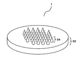
- FIG. 1 is a perspective view of a needle-shaped body of the present invention.
- FIG. 2 is a schematic cross-sectional view of the acicular body of the present invention.
- FIG. 3 is a schematic cross-sectional view of the acicular body of the present invention.
- FIG. 4 is an explanatory view of the method for manufacturing the needle-shaped body of the present invention, and is an explanatory view of the manufacturing method in the case of manufacturing the needle-shaped body shown in FIG.
- FIG. 5 is an explanatory view of the method for manufacturing the needle-shaped body of the present invention, and is an explanatory view of the manufacturing method in the case of manufacturing the needle-shaped body shown in FIG.
- FIG. 4 is an explanatory view of the method for manufacturing the needle-shaped body of the present invention, and is an explanatory view of the manufacturing method in the case of manufacturing the needle-shaped body shown in FIG.
- FIG. 5 is an explanatory view of the method for manufacturing the needle-shaped body of the present invention, and is an explan
- FIG. 6 is an explanatory view of the method for manufacturing the needle-shaped body of the present invention, and is an explanatory view of the manufacturing method in the case of manufacturing the needle-shaped body shown in FIG.
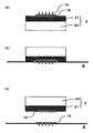
- FIG. 7 is an explanatory view of the method of puncturing the skin of the needle-shaped body of the present invention.
- FIG. 8 is an explanatory view of a method of puncturing the needle-like body of the present invention (another aspect).
- the method for manufacturing a needle-shaped body according to the present invention is a method for manufacturing a needle-shaped body including a protrusion having a needle-like shape and a support substrate that supports the protrusion, and has a recess corresponding to the protrusion.
- the peel strength between the protrusion side layer and the support substrate side layer of the obtained needle-like body can be reduced, and the needle-like body is projected after puncturing the skin. Only the support substrate side layer can be peeled from the skin while the partial side layer is in contact with the skin.
- the peel strength of the protrusion side layer and the support substrate side layer is 8 N / 15 mm width or less.
- the step of supplying the aqueous solution of the protrusion side layer forming material to the intaglio plate the step of supplying the aqueous solution of the supporting substrate side layer forming material to the intaglio plate, It is preferable to provide the process of drying the aqueous solution of the protrusion side layer forming material.
- a drying step is once provided, so that the needle-shaped body manufacturing method performs drying after the step of supplying the aqueous solution of the protruding portion side layer forming material to the intaglio.
- the specific gravity of the aqueous solution of the protrusion side layer forming material is larger than the specific gravity of the aqueous solution of the support substrate side layer forming material.
- the peeling strength of the protrusion part side layer and support substrate side layer of the acicular body obtained can be made small.
- a needle-shaped body is manufactured by performing a step of supplying an aqueous solution of the supporting substrate side layer forming material to the intaglio without drying after a step of supplying the aqueous solution of the protruding portion side layer forming material to the intaglio.
- the specific gravity relationship of the two aqueous solutions be the above-described magnitude relationship.
- the drying step is once provided after the step of supplying the aqueous solution of the protrusion side layer forming material, the protrusion side layer of the needle-like body obtained even if the specific gravity of the two aqueous solutions does not satisfy the above magnitude relationship And the peeling strength of the support substrate side layer can be made small.
- the method for producing the needle-shaped body of the present invention includes a material in which the protrusion side layer forming material is selected from pullulan and dextran, and the supporting substrate side layer forming material is hydroxypropylcellulose, hydroxyethylcellulose, methylcellulose, hydroxypropyl. Preferably it comprises a material selected from methylcellulose.
- the aqueous solution of the protrusion side layer forming material and the aqueous solution of the support substrate side layer forming material can be made into a liquid-liquid dispersion system. The peel strength between the side layer and the support substrate side layer can be reduced.
- the needle-like body of the present invention is a needle-like body including a protrusion having a needle-like shape and a support substrate that supports the protrusion, and at least two of the protrusion-side layer and the support substrate-side layer.
- a peeling strength of the protrusion side layer and the support substrate side layer is 8 N / 15 mm width or less.
- the needle-like body of the present invention is a needle-like body including a protrusion having a needle-like shape and a support substrate that supports the protrusion, and at least two of the protrusion-side layer and the support substrate-side layer.
- the protrusion side layer forming material includes a material selected from pullulan and dextran
- the support substrate side layer forming material includes a material selected from hydroxypropylcellulose, hydroxyethylcellulose, methylcellulose, and hydroxypropylmethylcellulose. It is characterized by that.
- the needle-like body selected and formed from these materials can have a small peel strength between the protrusion side layer and the support substrate side layer of the obtained needle-like body, and the needle-like body is projected after puncturing the skin. Only the support substrate side layer can be peeled from the skin while the partial side layer is in contact with the skin.
- FIG. 1 shows a perspective view of the needle-shaped body of the present invention.
- FIG. 2 shows a schematic diagram of the needle-shaped body of the present invention.
- the needle-like body of the present invention is characterized by comprising at least two layers of the protrusion side layer and the support substrate side layer. However, the needle-like body shown in FIGS. The part side layer and the support substrate side layer are not shown.
- the needle-like body of the present invention refers to a molded body composed of the support substrate 32 and the protrusion 34.
- the shape of the protrusion may be any shape that is suitable for puncturing the skin, and may be designed as appropriate. Specifically, the shape of the protrusion may be a cone, a pyramid, a cylinder, a prism, a pencil shape (a body portion is a columnar shape, and a tip portion is a cone shape), or the like. Moreover, either (1) the shape of one protrusion on the support substrate or (2) the shape of a plurality of protrusions standing on the support substrate may be used.
- array shape indicates a state in which the unit needle-like bodies are arranged, and includes, for example, patterns such as a lattice arrangement, a close-packed arrangement, a concentric arrangement, and a random arrangement. Shall be.
- FIG. 2A is a top view from the protrusion side of the needle-like body
- FIG. 2B is a cross-sectional view taken along the II ′ plane of the needle-like body in FIG. 2A.
- the size of the needle-like protrusion 34 has a thickness and length suitable for forming a puncture hole in the skin.
- the height H of the protrusion 34 shown in FIG. 2 is preferably in the range of 10 ⁇ m to 1000 ⁇ m.
- the height H of the protrusion is a distance from the support substrate 32 to the tip of the protrusion 34.
- the height H of the protrusion is preferably determined in consideration of how deep the puncture hole formed when the needle-like body is punctured within the above range is formed in the skin.
- the height H of the protrusion of the needle-like body is, for example, 10 ⁇ m or more and 300 ⁇ m or less, more preferably 30 ⁇ m or more and 200 ⁇ m or less, It is desirable to be within the range.
- the height H of the protrusion of the needle-like body is 200 ⁇ m or more and 700 ⁇ m. In the following, it is more preferable that the thickness be in the range of 200 ⁇ m to 500 ⁇ m, more preferably 200 ⁇ m to 300 ⁇ m. Furthermore, when the puncture hole formed when the needle-like body is punctured is “the length that the puncture hole reaches the dermis”, the height H of the protrusion of the needle-like body is in the range of 200 ⁇ m or more and 500 ⁇ m or less. It is preferable to do.
- the height H of the projection of the needle-like body is in the range of 200 ⁇ m or more and 300 ⁇ m or less. It is preferable.
- the width D of the protrusion is preferably in the range of 1 ⁇ m to 300 ⁇ m.
- the width D of the protrusion is preferably determined in consideration of the depth of the puncture hole formed when the needle-like body is punctured within the above range.
- the width D of the protrusion is the maximum length of the protrusions in contact with the support substrate when the protrusion is projected in parallel with the substrate surface. For example, when the projection is conical, the diameter of the circle on the surface in contact with the projection and the support substrate is the width D.
- the protrusion is a regular quadrangular pyramid, the square diagonal of the surface in contact with the protrusion and the support substrate is the width D.
- the protrusion is a cylinder
- the diameter of the circle on the surface in contact with the protrusion and the support substrate is the width D.
- the protrusion is a regular quadrangular prism
- the square diagonal of the surface in contact with the protrusion and the support substrate is the width D.
- the aspect ratio is preferably in the range of 1 to 10.
- the tip angle ⁇ of the projection is 5 ° or more and 30 ° or less, more preferably 10 ° or more. It is desirable to be within the range of 20 ° or less.
- the tip angle ⁇ indicates the largest angle (vertical angle) when the protrusion is projected in parallel with the support substrate surface.
- FIG. 3 shows a schematic cross-sectional view of the needle-shaped body of the present invention.
- the needle-shaped body of the present invention is characterized by comprising at least two layers of a protrusion side layer and a support substrate side layer, and the protrusion side layer and the support substrate side layer are composed of different components.
- the protrusion side layer 16 and the support substrate side layer 18 are separated in the support substrate 32.
- the protruding portion side layer 16 and the supporting substrate side layer 18 are separated in the support substrate 32, and the protruding portion in the support substrate 32 is further separated.
- the side layer 16 is formed with an area smaller than the outer shape of the support substrate.
- the protruding portion side layer 16 and the supporting substrate side layer 18 are separated at the joining position of the supporting substrate 32 and the protruding portion 34.
- the protrusion side layer 16 and the support substrate side layer 18 are separated in the protrusion 34.
- the protrusion side layer 16 and the support substrate side layer 18 are Japanese Industrial Standard JIS K6854-1 (1999) “Adhesive—Peeling Adhesive Strength Test Method—Part 1: 90 degrees.
- the peel strength measured by the “peeling test” is 8 N / 15 mm width or less.
- the peel strength between the protrusion side layer and the support substrate side layer is 8 N / 15 mm width or less, and both layers are easily peeled off, so that the protrusion side layer is brought into contact with the skin after puncturing the needle-like body into the skin.
- the support substrate side layer can be peeled off from the skin, and the needle-like body piercing the skin can be made inconspicuous. Therefore, it is possible to improve the appearance problem during use.
- the effect of the present invention can be increased.
- the peel strength between the protruding portion side layer 16 and the support substrate side layer 18 is 0.5 N / 15 mm width or more and 8 N / 15 mm width or less.
- the peel strength between the protrusion side layer 16 and the support substrate side layer 18 is preferably 1 N / 15 mm width or more and 3 N / 15 mm width or less.
- the material constituting the protrusion side layer 16 is preferably a biodegradable polysaccharide, such as dextran, dextrin, pectin, pullulan, chondroitin sulfate, alginate, chitosan, carboxymethylcellulose, hydroxy Examples include methyl cellulose, hydroxyethyl cellulose, hydroxypropyl cellulose, methyl cellulose, and ethyl cellulose. Moreover, the mixture of these biodegradable polysaccharides may be sufficient.
- a biodegradable polysaccharide as the protrusion side layer 16 can be dissolved in the skin after the needle-like body is punctured into the skin. Therefore, when a medicinal component is contained in the protrusion side layer, the delivery product can be rapidly introduced into the skin.
- the material constituting the support substrate side layer 18 is preferably a polysaccharide and a flexible material, such as dextran, dextrin, pectin, pullulan, chondroitin sulfate, alginate, chitosan, carboxymethylcellulose, hydroxymethylcellulose, hydroxyethylcellulose, Examples include hydroxypropyl cellulose, methyl cellulose, and ethyl cellulose. Moreover, the mixture of these biodegradable polysaccharides may be sufficient.
- pullulan or dextran as the material constituting the protruding portion side layer 16 and to use a material selected from hydroxypropylcellulose, hydroxyethylcellulose, methylcellulose, and hydroxypropylmethylcellulose as the material constituting the support substrate side layer 18. .
- a material selected from hydroxypropylcellulose, hydroxyethylcellulose, methylcellulose, and hydroxypropylmethylcellulose as the material constituting the support substrate side layer 18.
- the peel strength between the protrusion side layer and the support substrate side layer can be easily reduced to 8 N / 15 mm width or less.
- the combination of the aqueous solution of this material becomes a liquid-liquid dispersion system, and the specific gravity of the aqueous solution of the material constituting the protruding portion side layer 16 is higher than that of the aqueous solution of the material constituting the supporting substrate side layer 18. Because it ’s big.
- the needle-shaped body of the present invention can include a delivery product for delivery into the skin.
- Delivery products can include pharmacologically active substances and cosmetic delivery products.
- a material having a fragrance is used as a delivery product, an odor can be imparted during use, which is preferable for use as a cosmetic product.
- the pharmacologically active substance may be appropriately selected depending on the application.
- it may be a vaccine such as influenza, an anti-pain drug for cancer patients, insulin, a biologic, a gene therapy drug, an injection, an oral preparation, a preparation for skin application, and the like.
- the needle-shaped body of the present invention punctures the skin, it can be applied to pharmacologically active substances that require subcutaneous injection in addition to pharmacologically active substances that are conventionally used for transdermal administration.
- vaccines that are injections are suitable for application to children because there is no pain in administration when needles are used.
- the delivery product is contained in the needle-like body.
- the drug that does not elute into the skin and remains on the support substrate of the needle-like body is wasted.
- the waste of the drug can be solved.
- the cosmetic composition is a composition used as a cosmetic and a beauty product.
- moisturizers, colorants, fragrances, and physiologically active substances that exhibit cosmetic effects (improvement effect on wrinkles, acne, pregnancy lines, improvement effect on hair loss, etc.), and the like.
- the delivered substance when the depth of the puncture hole is kept “in the stratum corneum”, the delivered substance can be retained in the stratum corneum. Since the stratum corneum is constantly generated by metabolism, the deliverables in the stratum corneum are discharged out of the body with time. For this reason, a delivery thing can be excluded by washing
- the delivery product when the puncture hole is kept at a length that does not penetrate the stratum corneum and does not reach the nerve layer, the delivery product can be delivered to a position deeper than the stratum corneum. Since the puncture hole formed in the stratum corneum is closed over time, the delivery delivered under the stratum corneum is held in the living body while being blocked by the stratum corneum from the outside. For this reason, the delivered product can be reduced for exfoliation due to metabolism of the stratum corneum and washing such as skin care, and can be held for a long time.
- the needle-like body of the present invention is characterized in that the protrusion side layer and the support substrate side layer are composed of different components.
- Consisting of different components means that the polysaccharides used in the protrusion side layer and the support substrate side layer may be different materials, and the polysaccharides used in the protrusion side layer and the support substrate side layer are the same and delivered. Other components such as objects may be different materials.
- the protruding portion side layer and the supporting substrate side layer are not clearly separated, and the protruding portion side layer and the supporting substrate side layer are interposed between the protruding portion side layer and the supporting substrate side layer. Do not exclude needles with mixed layers of layers. In the needle-like body having a mixed layer of the protruding portion side layer and the supporting substrate side layer, the peeling strength between the protruding portion side layer and the supporting substrate side layer, which will be described later, can be increased.
- the delivery product can be contained only in the protrusion side layer and not contained in the support substrate side layer. By containing the delivery product only in the protrusion side layer, the delivery product can be used efficiently.
- the delivery product when the delivery product is administered with a needle-like body, the delivery product may be applied onto the target skin before or after the needle-like body is punctured into the skin. At this time, the delivery material may be placed on the needle-like body, and the delivery material may be applied to the target skin surface.
- the needle-shaped body of the present invention may include a delivery product on the surface of the protrusion.
- the support substrate may have flexibility.
- a flexible support substrate it is possible to puncture a flexible object such as a curved surface or biological skin.
- the roller which the protrusion part stood can be formed by making it roll shape.
- an applicator for fixing the insertion position and direction may be used.
- FIG. 4 shows an explanatory diagram of the method for producing the needle-shaped body of the present invention.
- FIG. 4 shows an explanatory view of a manufacturing method in the case of manufacturing the needle-shaped body shown in FIG.
- aqueous solution of a material for forming the protruding portion side layer 16 and the support substrate side layer 18 is prepared.
- an intaglio 10 having a needle-like pattern is prepared (FIG. 4A).
- a manufacturing method of the original plate for determining the shape of the needle-shaped body a known manufacturing method may be appropriately used according to the shape of the needle-shaped body.
- the original plate may be formed using a fine processing technique. For example, a lithography method, a wet etching method, a dry etching method, a sand blasting method, a laser processing method, or a precision machining method may be used as the fine processing technology. good.
- a known shape transfer method may be used as appropriate. For example, (1) Ni intaglio is formed by Ni electroforming, and (2) transfer molding using a molten resin.
- an aqueous solution 16 ′ of a material for forming the protrusion side layer is supplied to the intaglio 10.
- the solvent of the aqueous solution 16 ′ of the material forming the protrusion side layer may be any solvent that dissolves the needle-shaped body material, and water is used. In addition to water, other solvent components such as alcohol may be added.
- heat drying may be performed.
- mixing in the vicinity of the interface with the aqueous solution 18 ′ of the material forming the support substrate side layer to be filled next can be suppressed.
- the specific gravity of the aqueous solution 18 ′ of the material forming the support substrate side layer is larger than that of the aqueous solution 16 ′ of the material forming the protrusion side layer, it is better to perform heat drying.
- an aqueous solution 18 ′ of a material for forming the support substrate side layer is supplied on the protrusion side layer 16.
- the solvent of the aqueous solution 18 ′ of the material forming the support substrate side layer may be any solvent that dissolves the acicular material, and water is used. In addition to water, other solvent components such as alcohol may be added.
- the aqueous solution 16 ′ of the material forming the protrusion side layer and the aqueous solution 18 ′ of the material forming the support substrate side layer be a liquid-liquid dispersion system that does not mix with each other.
- the specific gravity of the aqueous solution 16 ′ of the material forming the protrusion side layer is larger than that of the aqueous solution 18 ′ of the material forming the support substrate side layer.
- the aqueous solution 16 ′ of the material forming the protrusion side layer and the aqueous solution 18 ′ of the material forming the support substrate side layer are liquid-liquid dispersion systems that do not mix with each other, and the material of the material forming the protrusion side layer
- the aqueous solution 16 ′ of the material forming the protrusion side layer can be a pullulan aqueous solution, a dextran aqueous solution, a support substrate side
- a combination of a hydroxypropylcellulose aqueous solution, a hydroxycellulose aqueous solution, a methylcellulose aqueous solution, and a hydroxypropylmethylcellulose aqueous solution can be selected.
- a known method may be appropriately selected according to the shape and dimensions of the intaglio.
- a spin coating method for example, a spin coating method, an inkjet method, a method using a dispenser, a casting method, or the like may be used.
- the environment around the intaglio may be under reduced pressure or under vacuum.
- the aqueous solution 18 ′ of the material forming the support substrate side layer is dried and solidified.
- the drying method may be appropriately selected according to the environment such as natural drying, bottom surface heating using a hot plate, and drying by hot air drying.
- the drying temperature must be such that the aqueous solution does not boil.
- the drying temperature is preferably at least 110 ° C. or lower.
- the acicular body 1 can be obtained by peeling from the intaglio 10 after the drying. Since the aqueous solution 16 ′ of the material forming the protrusion side layer and the aqueous solution 18 ′ of the material forming the support substrate side layer form a liquid-liquid dispersion system that does not mix with each other, the aqueous solution of the material forming the protrusion side layer 16 'and the aqueous solution 18' of the material forming the support substrate side layer are dried while maintaining a two-layer state, and a needle-like body having a two-layer structure can be obtained.
- FIG. 5 shows an explanatory diagram of the method for producing the needle-shaped body of the present invention.
- FIG. 5 shows an explanatory diagram of a manufacturing method in the case of manufacturing the needle-shaped body shown in FIG.
- FIG. 5 when the intaglio 10 having a needle-like pattern is prepared (FIG. 5 (a)), it is possible to remove the intaglio 10 and surround the outer edge portion of the portion corresponding to the support substrate of the intaglio. Two editions 11 are prepared.
- an aqueous solution 16 ′ of a material for forming the protrusion side layer is supplied to the intaglio 10.
- the aqueous solution in the intaglio is dried.
- heat drying is preferable, and by performing drying, mixing in the vicinity of the interface with the aqueous solution 18 ′ of the material forming the support substrate side layer to be filled next can be suppressed.
- the second plate 11 is removed from the intaglio plate. After removing the second plate from the intaglio plate, as shown in FIG. 5C, an aqueous solution 18 ′ of a material for forming the support substrate side layer is supplied on the protrusion side layer 16.
- the aqueous solution 18 ′ of the material forming the support substrate side layer is dried and solidified. If it peels from the intaglio 10 after completion
- FIG. 6 shows an explanatory diagram of the method for producing the needle-shaped body of the present invention.
- FIG. 6 shows an explanatory diagram of a manufacturing method in the case of manufacturing the needle-shaped body shown in FIG.
- an intaglio 10 having a needle-like pattern is prepared (FIG. 6 (a)).
- an aqueous solution 16 ′ of a material for forming the protrusion side layer is supplied to the intaglio 10.
- an aqueous solution 16 ′ of a material for forming the protrusion side layer is supplied to the protrusion corresponding part of the intaglio by the ink jet method.
- an aqueous solution 16 ′ of a material for forming the protruding portion side layer is discharged from the inkjet nozzle 14.
- the aqueous solution in the intaglio is dried.
- drying heat drying is preferable, and by performing drying, mixing in the vicinity of the interface with the aqueous solution 18 ′ of the material forming the support substrate side layer to be filled next can be suppressed.
- an aqueous solution 18 ′ of a material for forming the support substrate side layer is supplied on the protrusion side layer 16.
- the aqueous solution 18 ′ of the material forming the support substrate side layer is dried and solidified. After drying, the film is peeled from the intaglio 10 to obtain a needle-like body shown in FIG.
- an aqueous solution 16 ′ of a material for forming the projection-side layer on the intaglio 10 is used.
- an inkjet method can be suitably used. By using the inkjet method, the amount of expensive delivery materials used can be greatly reduced.
- FIG. 7 shows an explanatory view of the method of puncturing the skin of the needle-shaped body of the present invention.
- the acicular body provided with the protrusion side layer 16 and the support substrate side layer 18 of the present invention is prepared (FIG. 7A).
- the needle-like body of the present invention is punctured into the skin S (FIG. 7 (b)).
- the needle-shaped body of the present invention is peeled off at the interface between the protruding portion side layer 16 and the support substrate side layer 18 (FIG. 7C).
- the protrusion-side layer and the support substrate-side layer are easily peeled off, so that the needle-like body is in contact with the skin after the needle-like body is punctured into the skin. Only the support substrate side layer can be peeled off from the skin, and the needle-like body piercing the skin can be made inconspicuous.
- FIG. 8 shows an explanatory view (another aspect) of the method of puncturing the needle-like body of the present invention into the skin.
- the pressure-sensitive adhesive tape 2 is attached to the support substrate side of the needle-like body including the protrusion side layer 16 and the support substrate side layer 18 of the present invention.
- the pressure-sensitive adhesive tape 2 includes a pressure-sensitive adhesive layer 21 on the base material 22.
- FIG. 8 (a) the needle-like body fixed to the adhesive tape 2 is punctured into the skin S
- FIG. 8C the needle-shaped body of the present invention is peeled off at the interface between the protrusion side layer 16 and the support substrate side layer 18
- the needle-shaped body of the present invention In the method of puncturing the skin using the needle-shaped body of the present invention, after the needle-shaped body is punctured into the skin S (FIG. 8B), the needle-shaped body is punctured into the skin. After sticking on the skin with the adhesive layer of the adhesive tape and holding it, the needle-shaped body of the present invention can be peeled off at the interface between the protrusion side layer 16 and the support substrate side layer 18 (FIG. 8C).
- Example 1 The needle-shaped body shown in FIG. 3A was produced by the following method. (1) First, acicular body original plates were formed on a silicon substrate by using precision machining, with 36 square pyramids (bottom surface 38 ⁇ m ⁇ 38 ⁇ m, height 120 ⁇ m) arranged in a grid of 6 rows and 6 rows at 1 mm intervals. . Next, a nickel film having a thickness of 500 ⁇ m is formed on the acicular body original plate formed of the silicon substrate by plating, and the silicon substrate is heated with a 30% by weight potassium hydroxide aqueous solution heated to 90 ° C. The intaglio plate made of nickel was prepared by wet etching.
- a 10% by weight aqueous solution of pullulan (Tokyo Chemical Industry Co., Ltd.) and a 10% by weight hydroxypropyl cellulose (Tokyo Chemical Industry Co., Ltd.) aqueous solution were prepared.
- the prepared intaglio was filled with an aqueous pullulan solution by using a spin coating method.
- An intaglio plate filled with an aqueous pullulan solution was placed on a hot plate set at 90 ° C. and dried for 30 minutes to evaporate water.
- a hydroxypropyl cellulose aqueous solution was applied to the intaglio plate on which a layer made of pullulan was formed by using a spin coating method.
- the acicular body was peeled from the intaglio.
- Example 2 The needle-shaped body shown in FIG. 3A was produced by the following method. (1) First, the same intaglio plate made of nickel as in Example 1 was prepared. (2) A 10% by weight aqueous solution of pullulan (Tokyo Chemical Industry Co., Ltd.) and a 1% by weight aqueous solution of methylcellulose (Tokyo Chemical Industry Co., Ltd.) were prepared. (3) The prepared intaglio was filled with an aqueous pullulan solution by using a spin coating method. (4) An intaglio plate filled with an aqueous pullulan solution was placed on a hot plate set at 90 ° C. and dried for 30 minutes to evaporate water.
- Example 3 The needle-shaped body shown in FIG. 3A was produced by the following method. (1) First, the same intaglio plate made of nickel as in Example 1 was prepared. (2) A 10% by weight aqueous solution of pullulan (Tokyo Chemical Industry Co., Ltd.) and a 10% by weight hydroxyethyl cellulose (Tokyo Chemical Industry Co., Ltd.) aqueous solution were prepared. (3) The intaglio plate produced was filled with an aqueous pullulan solution using an inkjet method. (4) An intaglio plate filled with an aqueous pullulan solution was placed on a hot plate set at 90 ° C. and dried for 30 minutes to evaporate water.
- pullulan Tokyo Chemical Industry Co., Ltd.
- hydroxyethyl cellulose Tokyo Chemical Industry Co., Ltd.
- Example 4 The needle-shaped body shown in FIG. 3A was produced by the following method. (1) First, the same intaglio plate made of nickel as in Example 1 was prepared. (2) A 10% by weight aqueous solution of pullulan (Tokyo Chemical Industry Co., Ltd.) and a 10% by weight hydroxypropyl cellulose (Tokyo Chemical Industry Co., Ltd.) aqueous solution were prepared. (3) The prepared intaglio was filled with an aqueous pullulan solution by using a spin coating method.
- Example 5 The needle-shaped body shown in FIG. 3A was produced by the following method. (1) First, the same intaglio plate made of nickel as in Example 1 was prepared. (2) A 10% by weight dextran (Tokyo Chemical Industry Co., Ltd.) aqueous solution and a 10% by weight hydroxypropyl cellulose (Tokyo Chemical Industry Co., Ltd.) aqueous solution were prepared. (3) The prepared intaglio was filled with a dextran aqueous solution using a spin coating method.
- a needle-like body was produced by the following method. (1) First, the same intaglio plate made of nickel as in Example 1 was prepared. (2) A 10% by weight aqueous solution of hydroxypropylcellulose (Tokyo Chemical Industry Co., Ltd.) was prepared. (3) The prepared intaglio was filled with an aqueous hydroxypropylcellulose solution using a spin coating method. (4) An intaglio plate filled with an aqueous hydroxypropylcellulose solution was placed on a hot plate set at 90 ° C., and dried for 30 minutes to evaporate water.
- hydroxypropylcellulose Tokyo Chemical Industry Co., Ltd.
- a needle-like body was produced by the following method.
- An intaglio plate filled with an aqueous pullulan solution was placed on a hot plate set at 90 ° C. and dried for 30 minutes to evaporate water.
- a pullulan aqueous solution was applied to the intaglio plate on which a layer made of pullulan was formed by using a spin coating method.
- (7) The acicular body was peeled from the intaglio.
- a needle-like body was produced by the following method.
- An intaglio plate filled with an aqueous pullulan solution was placed on a hot plate set at 90 ° C. and dried for 30 minutes to evaporate water.
- a sodium alginate aqueous solution was applied to the intaglio in which the layer made of pullulan was formed by using a spin coating method.
- the acicular body was peeled from the intaglio.
- a pullulan aqueous solution or a dextran aqueous solution was present at the bottom of the beaker, and a hydroxypropylcellulose aqueous solution, a methylcellulose aqueous solution, or a hydroxyethylcellulose aqueous solution was present at the top of the beaker. It was confirmed that the pullulan aqueous solution or dextran aqueous solution had a higher specific gravity than the hydroxypropyl cellulose aqueous solution, methyl cellulose aqueous solution or hydroxyethyl cellulose aqueous solution.
- Examples 1 to 5 had two layers. Had a structure.
- Comparative Example 3 it was observed that sodium alginate and pullulan were mixed at the interface between the protrusion side layer and the support substrate side layer.
- Example 4 although a two-layer structure was confirmed, it was observed that hydroxypropylcellulose and pullulan were partially mixed at the interface between the protrusion side layer and the support substrate side layer.
- Comparative Example 1 and Comparative Example 2 have a single layer structure, and no interface was confirmed.
- Example 5 since the protrusion side layer aqueous solution filled in the intaglio was once dried, the formed needle-like body had a two-layer structure in which the interface was clearly confirmed.
- Example 4 in which the drying after filling the protrusion side layer solution was not performed, it was confirmed that the material was partially mixed at the interface between the protrusion side layer and the support substrate side layer although it had a two-layer structure. The peel strength of the two layers was slightly stronger than that of Example 1, and a force of 1.5 N / 15 mm width was required.
- Comparative Example 3 since the sodium alginate and pullulan were mixed at the interface between the protrusion side layer and the support substrate side layer, the adhesive strength of the two layers was strong, and a force of 9.5 N / 15 mm width was required. there were.
- the acicular body of the present invention can be used in various fields that require fine acicular bodies. For example, it can be expected to be applied as a needle-like body used for MEMS devices, optical members, sample jigs, drug discovery, medical use, cosmetics, cosmetic use, and the like.
Landscapes
- Health & Medical Sciences (AREA)
- Dermatology (AREA)
- General Health & Medical Sciences (AREA)
- Veterinary Medicine (AREA)
- Public Health (AREA)
- Life Sciences & Earth Sciences (AREA)
- Animal Behavior & Ethology (AREA)
- Engineering & Computer Science (AREA)
- Epidemiology (AREA)
- Pharmacology & Pharmacy (AREA)
- Medicinal Chemistry (AREA)
- Chemical & Material Sciences (AREA)
- Medical Informatics (AREA)
- Anesthesiology (AREA)
- Biomedical Technology (AREA)
- Heart & Thoracic Surgery (AREA)
- Hematology (AREA)
- Media Introduction/Drainage Providing Device (AREA)
- Materials For Medical Uses (AREA)
- Medicinal Preparation (AREA)
Abstract
Description
また、請求項2に係る発明としては、前記突起部側層及び前記支持基板側層の剥離強度が8N/15mm巾以下であることを特徴とする請求項1記載の針状体の製造方法とした。
また、請求項3に係る発明としては、前記凹版に突起部側層形成材料の水溶液を供給する工程の後、前記凹版に支持基板側層形成材料の水溶液を供給する工程の前に、前記凹版内の突起部側層形成材料の水溶液を乾燥する工程を備えることを特徴とする請求項1記載の針状体の製造方法とした。
また、請求項4に係る発明としては、前記突起部側層形成材料の水溶液の比重が、前記支持基板側層形成材料の水溶液の比重よりも大きいことを特徴とする請求項1記載の針状体の製造方法とした。
また、請求項5に係る発明としては、前記突起部側層形成材料がプルラン、デキストランから選択される材料を含み、前記支持基板側層形成材料がヒドロキシプロピルセルロース、ヒドロキシエチルセルロース、メチルセルロース、ヒドロキシプロピルメチルセルロースから選択される材料を含むことを特徴とする請求項1記載の針状体の製造方法とした。
また、請求項6に係る発明としては、針状形状を有する突起部と、前記突起部を支持する支持基板とを備えた針状体であって、突起部側層と支持基板側層の少なくとも2層を備え、前記突起部側層及び前記支持基板側層の剥離強度が8N/15mm巾以下であることを特徴とする針状体とした。
また、請求項7に係る発明としては、針状形状を有する突起部と、前記突起部を支持する支持基板とを備えた針状体であって、突起部側層と支持基板側層の少なくとも2層を備え、前記突起部側層形成材料がプルラン、デキストランから選択される材料を含み、前記支持基板側層形成材料がヒドロキシプロピルセルロース、ヒドロキシエチルセルロース、メチルセルロース、ヒドロキシプロピルメチルセルロースから選択される材料を含むことを特徴とする針状体とした。
本構成の針状体の製造方法とすることにより、得られる針状体の突起部側層と支持基板側層の剥離強度を小さなものとすることができ、針状体を皮膚に穿刺後に突起部側層を皮膚に接触させた状態で支持基板側層のみを皮膚から剥離することができる。
突起部側層形成材料の水溶液を供給する工程の後、一旦乾燥工程を設けることにより、針状体の製造方法は、凹版に突起部側層形成材料の水溶液を供給する工程の後に乾燥をおこなうことなく凹版に支持基板側層形成材料の水溶液を供給する工程をおこなった針状体の製造方法と比較して、得られる針状体の突起部側層と支持基板側層の剥離強度を小さなものとすることができる。
本発明の針状体1において、針状の突起部34の寸法は皮膚に穿刺孔を形成するのに適した細さと長さを有することが好ましい。具体的には、図2に示す突起部34の高さHは10μm以上1000μm以下の範囲内であることが好ましい。突起部の高さHは、支持基板32から突起部34の先端までの距離である。
突起部の高さHは、前記範囲内で針状体を穿刺した際に形成される穿刺孔を皮膚内のどのくらいの深さまで形成するかを考慮して決定することが好ましい。
特に、針状体を穿刺した際に形成される穿刺孔を「角質層内」に留める場合、針状体の突起部の高さHは例えば10μm以上300μm以下、より好ましくは30μm以上200μm以下、の範囲内にすることが望ましい。
また、針状体を穿刺した際に形成される穿刺孔を「角質層を貫通し、かつ神経層へ到達しない長さ」に留める場合、針状体の突起部の高さHは200μm以上700μm以下、より好ましくは200μm以上500μm以下、さらに好ましくは200μm以上300μm以下、の範囲内にすることが望ましい。
さらに、針状体を穿刺した際に形成される穿刺孔を「穿刺孔が真皮に到達する長さ」とする場合、針状体の突起部の高さHは200μm以上500μm以下の範囲内とすることが好ましい。また、針状体を穿刺した際に形成される穿刺孔を「穿刺孔が表皮に到達する長さ」の場合、針状体の突起部の高さHは200μm以上300μm以下の範囲内とすることが好ましい。
突起部の幅Dは、突起部を基板面と平行に投影した際の支持基板と接している突起部の長さのうち最大の長さである。例えば、突起部が円錐状である場合、突起部と支持基板と接している面の円の直径が幅Dとなる。突起部が正四角錐である場合、突起部と支持基板と接している面の正方形の対角線が幅Dとなる。また、突起部が円柱である場合、突起部と支持基板と接している面の円の直径が幅Dとなる。突起部が正四角柱である場合、突起部と支持基板と接している面の正方形の対角線が幅Dとなる。
実施形態に係る針状体において、突起部が錐形状のように先端角を有し、角質層を貫通させる場合、突起部の先端角θは5°以上30°以下、より好ましくは10°以上20°以下、の範囲内であることが望ましい。なお、先端角θは突起部を支持基板面と平行に投影した際の角度(頂角)のうち最大のものを指す。
図3(a)に記載の本発明の針状体にあっては、支持基板32内で突起部側層16と支持基板側層18が分離している。
図3(b)に記載の本発明の針状体にあっては、支持基板32内で突起部側層16と支持基板側層18が分離しており、さらに、支持基板32内における突起部側層16が支持基板の外形よりも小さい面積で形成されている。
図3(c)に記載の本発明の針状体にあっては、支持基板32と突起部34の接合位置で、突起部側層16と支持基板側層18が分離している。
図3(d)に記載の本発明の針状体にあっては、突起部34内で、突起部側層16と支持基板側層18が分離している。
突起部側層16と支持基板側層18を形成する材料の水溶液をそれぞれ調製する。
次に、針状パターンを有する凹版10を用意する(図4(a))。針状体の形状を決定する原版の製造方法としては、針状体の形状に応じて適宜公知の製造方法を用いてよい。このとき、微細加工技術を用いて原版を形成してよく、微細加工技術として、例えば、リソグラフィ法、ウェットエッチング法、ドライエッチング法、サンドブラスト法、レーザー加工法、精密機械加工法などを用いても良い。原版から凹版を形成する方法としては、適宜公知の形状転写法を用いてよい。例えば、(1)Ni電鋳法により、Niの凹版を形成、(2)溶融した樹脂を用いた転写成形、など、が挙げられる。
次に、図4(b)に示すように、前記凹版10に突起部側層を形成する材料の水溶液16´を供給する。突起部側層を形成する材料の水溶液16´の溶媒は針状体材料を溶解する溶媒であればよく、水を用いる。なお、水とあわせアルコール等の他の溶媒成分を添加しても良い。
次に、支持基板側層を形成する材料の水溶液18´を乾燥し、固化する。乾燥方法は、自然乾燥、ホットプレートを用いた底面加熱、熱風乾燥による乾燥など環境に応じて適宜選択してよい。ただし、乾燥温度は、水溶液が沸騰しない温度でおこなう必要がある。乾燥温度は、少なくとも110℃以下の温度でおこなうことが好ましい。
乾燥終了後に凹版10から剥離すると針状体1を得ることができる。突起部側層を形成する材料の水溶液16´と支持基板側層を形成する材料の水溶液18´が互いに混ざり合わない液液分散系を形成することから、突起部側層を形成する材料の水溶液16´と支持基板側層を形成する材料の水溶液18´が2層状態を保ちながら乾燥し、2層構造を有する針状体を得ることができる。
まず、本発明の突起部側層16と支持基板側層18を備える針状体を用意する(図7(a))。次に、本発明の針状体を皮膚Sに穿刺する(図7(b))。最後に、本発明の針状体を突起部側層16と支持基板側層18界面で剥離する(図7(c))。以上のように、本発明の針状体では、突起部側層と支持基板側層を剥離容易にすることにより、針状体を皮膚に穿刺後に突起部側層を皮膚に接触させた状態で支持基板側層のみを皮膚から剥離することができ、皮膚に穿刺している針状体を目立たなくすることができる。
まず、本発明の突起部側層16と支持基板側層18を備える針状体の支持基板側に粘着テープ2を貼着させる。粘着テープ2は、基材22上に粘着層21を備える。図8(a))。次に、粘着テープ2に固定された針状体を皮膚Sに穿刺する(図8(b))。最後に、本発明の針状体を突起部側層16と支持基板側層18界面で剥離する(図8(c))。
以下の方法により図3(a)に示す針状体を作製した。
(1)まず、シリコン基板に精密機械加工を用いて正四角錐(底面38μm×38μm、高さ120μm)が1mm間隔で、6列6行の格子状に36本配列した針状体原版を形成した。次に、前記シリコン基板で形成された針状体原版に、メッキ法によりニッケル膜を500μmの厚さに形成し、90℃に加熱した重量パーセント濃度30%の水酸化カリウム水溶液によって前記シリコン基板をウェットエッチングして除去し、ニッケルから成る凹版を作製した。
(2)10重量%のプルラン(東京化成工業株式会社)水溶液、及び10重量%のヒドロキシプロピルセルロース(東京化成工業株式会社)水溶液を調製した。
(3)スピンコート法を用いて、作製した凹版にプルラン水溶液を充填した。
(4)90℃に設定したホットプレート上にプルラン水溶液が充填された凹版を置き、30分乾燥させて水分を蒸発させた。
(5)スピンコート法を用いて、プルランからなる層が形成された凹版に、ヒドロキシプロピルセルロース水溶液を塗布した。
(6)室温で乾燥させ、針状体とした。
(7)凹版から針状体を剥離した。
以下の方法により図3(a)に示す針状体を作製した。
(1)まず、実施例1と同じニッケルから成る凹版を作製した。
(2)10重量%のプルラン(東京化成工業株式会社)水溶液、及び1重量%のメチルセルロース(東京化成工業株式会社)水溶液を調製した。
(3)スピンコート法を用いて、作製した凹版にプルラン水溶液を充填した。
(4)90℃に設定したホットプレート上にプルラン水溶液が充填された凹版を置き、30分乾燥させて水分を蒸発させた。
(5)スピンコート法を用いて、プルランからなる層が形成された凹版に、メチルセルロース水溶液を塗布した。
(6)室温で乾燥させ、針状体とした。
(7)凹版から針状体を剥離した。
以下の方法により図3(a)に示す針状体を作製した。
(1)まず、実施例1と同じニッケルから成る凹版を作製した。
(2)10重量%のプルラン(東京化成工業株式会社)水溶液、及び10重量%のヒドロキシエチルセルロース(東京化成工業株式会社)水溶液を調製した。
(3)インクジェット法を用いて、作製した凹版にプルラン水溶液を充填した。
(4)90℃に設定したホットプレート上にプルラン水溶液が充填された凹版を置き、30分乾燥させて水分を蒸発させた。
(5)スピンコート法を用いて、プルランからなる層が形成された凹版に、ヒドロキシエチルセルロース水溶液を塗布した。
(6)室温で乾燥させ、針状体とした。
(7)凹版から針状体を剥離した。
以下の方法により図3(a)に示す針状体を作製した。
(1)まず、実施例1と同じニッケルから成る凹版を作製した。
(2)10重量%のプルラン(東京化成工業株式会社)水溶液、及び10重量%のヒドロキシプロピルセルロース(東京化成工業株式会社)水溶液を調製した。
(3)スピンコート法を用いて、作製した凹版にプルラン水溶液を充填した。
(4)凹版に充填されたプルラン水溶液を乾燥することなく、スピンコート法を用いてプルラン水溶液が充填された凹版に対し、ヒドロキシプロピルセルロース水溶液を塗布した。
(6)室温で乾燥させた。
(7)(6)の凹版から針状体を剥離した。
以下の方法により図3(a)に示す針状体を作製した。
(1)まず、実施例1と同じニッケルから成る凹版を作製した。
(2)10重量%のデキストラン(東京化成工業株式会社)水溶液、及び10重量%のヒドロキシプロピルセルロース(東京化成工業株式会社)水溶液を調製した。
(3)スピンコート法を用いて、作製した凹版にデキストラン水溶液を充填した。
(4)凹版に充填されたデキストラン水溶液を乾燥することなく、スピンコート法を用いてデキストラン水溶液が充填された凹版に対し、ヒドロキシプロピルセルロース水溶液を塗布した。
(6)室温で乾燥させた。
(7)(6)の凹版から針状体を剥離した。
以下の方法により針状体を作製した。
(1)まず、実施例1と同じニッケルから成る凹版を作製した。
(2)10重量%のヒドロキシプロピルセルロース(東京化成工業株式会社)水溶液を調製した。
(3)スピンコート法を用いて、作製した凹版にヒドロキシプロピルセルロース水溶液を充填した。
(4)90℃に設定したホットプレート上にヒドロキシプロピルセルロース水溶液が充填された凹版を置き、30分乾燥させて水分を蒸発させた。
(5)スピンコート法を用いて、ヒドロキシプロピルセルロースからなる層が形成された凹版に、ヒドロキシプロピルセルロース水溶液を塗布した。
(6)室温で乾燥させ、針状体とした。
(7)凹版から針状体を剥離した。
以下の方法により針状体を作製した。
(1)まず、実施例1と同じニッケルから成る凹版を作製した。
(2)10重量%のプルラン(東京化成工業株式会社)水溶液を調製した。
(3)スピンコート法を用いて、作製した凹版にプルラン水溶液を充填した。
(4)90℃に設定したホットプレート上にプルラン水溶液が充填された凹版を置き、30分乾燥させて水分を蒸発させた。
(5)スピンコート法を用いて、プルランからなる層が形成された凹版に、プルラン水溶液を塗布した。
(6)室温で乾燥させ、針状体とした。
(7)凹版から針状体を剥離した。
以下の方法により針状体を作製した。
(1)まず、実施例1と同じニッケルから成る凹版を作製した。
(2)10重量%のプルラン(東京化成工業株式会社)水溶液、及び10重量%のアルギン酸ナトリウム(東京化成工業株式会社)水溶液を調製した。
(3)スピンコート法を用いて、作製した凹版にプルラン水溶液を充填した。
(4)90℃に設定したホットプレート上にプルラン水溶液が充填された凹版を置き、30分乾燥させて水分を蒸発させた。
(5)スピンコート法を用いて、プルランからなる層が形成された凹版に、アルギン酸ナトリウム水溶液を塗布した。
(6)室温で乾燥させ、針状体とした。
(7)凹版から針状体を剥離した。
<液液分散系及び比重の確認>
実施例1~実施例5及び比較例1~比較例3の針状体の製造方法に用いた2つの水溶液をビーカーに入れ5分放置した後、ビーカ内の水溶液の状態を確認した。実施例1~5の水溶液にあっては、各水溶液がビーカー内の上部と下部に分離している様子(界面)が確認され、液液分散系であることが確認された。一方、比較例1~3の水溶液にあっては、ビーカー内の上部と下部に分離している様子(界面)は確認されなかった。
また、実施例1~5の水溶液にあっては、ビーカー下部にプルラン水溶液あるいはデキストラン水溶液が存在し、ビーカーの上部にヒドロキシプロピルセルロース水溶液、メチルセルロース水溶液あるいはヒドロキシエチルセルロース水溶液が存在している様子が確認され、プルラン水溶液あるいはデキストラン水溶液のほうが、ヒドロキシプロピルセルロース水溶液、メチルセルロース水溶液あるいはヒドロキシエチルセルロース水溶液と比較して比重が大きいことが確認された。
<針状体の構造比較>
実施例1~実施例5及び比較例1~比較例3の針状体を支持基板に対して垂直に切断し、その断面を走査型電子顕微鏡により観察したところ、実施例1~5は2層構造を有していた。比較例3は、突起部側層と支持基板側層との界面において、アルギン酸ナトリウムとプルランが混ざり合っている様子が観察された。実施例4は2層構造が確認されたものの、突起部側層と支持基板側層との界面においてヒドロキシプロピルセルロースとプルランが一部混ざり合っている様子が観察された。比較例1及び比較例2は、単層構成であり界面は確認されなかった。
<針状体の90度剥離強度測定>
日本工業規格 JIS K6854-1(1999)「接着剤―はく離接着強さ試験方法―第1部:90度はく離試験」を参考に、突起部側層と支持基板側層の密着強度を測定した。凹版から剥離した針状体を、巾15mmの短冊状に切り出した。短冊状に切り出した針状体の一部を突起部側層と支持基板側層に剥離し、端部を引っ張り試験機のつかみ部分に固定した。このとき、90度剥離となるように端部を固定した。上記状態からつかみ移動速度50mm/minで引張試験をおこない、最大力を剥離強度とした。針状体の強度測定結果を表1に示す。なお、比較例1及び比較例2では、突起部側層と支持基板側層の接着強度が高く、突起部側層と支持基板側層の界面で剥離させることができなかった。

34・・・突起部
32・・・支持基板
16・・・突起部側層
18・・・支持基板側層
10・・・凹版
11・・・第2の版
16´・・突起部側層を形成する材料の水溶液
18´・・支持基板側層を形成する材料の水溶液
14・・・インクジェットノズル
2・・・粘着テープ
21・・・粘着層
22・・・基材
Claims (7)
- 針状形状を有する突起部と、前記突起部を支持する支持基板とを備えた針状体の製造方法であって、
前記突起部に対応した凹部を有する凹版に突起部側層形成材料の水溶液を供給する工程と、
前記凹版に支持基板側層形成材料の水溶液を供給する工程と、
前記凹版内の水溶液を乾燥し、針状体とする工程と、
前記凹版から針状体を剥離する工程とを備え、かつ、
前記突起部側層形成材料の水溶液と、支持基板側層形成材料の水溶液が液液分散系であることを特徴とする針状体の製造方法。 - 前記突起部側層及び前記支持基板側層の剥離強度が8N/15mm巾以下であることを特徴とする請求項1記載の針状体の製造方法。
- 前記凹版に突起部側層形成材料の水溶液を供給する工程の後、前記凹版に支持基板側層形成材料の水溶液を供給する工程の前に、前記凹版内の突起部側層形成材料の水溶液を乾燥する工程を備えることを特徴とする請求項1記載の針状体の製造方法。
- 前記突起部側層形成材料の水溶液の比重が、前記支持基板側層形成材料の水溶液の比重よりも大きいことを特徴とする請求項1記載の針状体の製造方法。
- 前記突起部側層形成材料がプルラン、デキストランから選択される材料を含み、前記支持基板側層形成材料がヒドロキシプロピルセルロース、ヒドロキシエチルセルロース、メチルセルロース、ヒドロキシプロピルメチルセルロースから選択される材料を含むことを特徴とする請求項1記載の針状体の製造方法。
- 針状形状を有する突起部と、前記突起部を支持する支持基板とを備えた針状体であって、
突起部側層と支持基板側層の少なくとも2層を備え、
前記突起部側層及び前記支持基板側層の剥離強度が8N/15mm巾以下であることを特徴とする針状体。 - 針状形状を有する突起部と、前記突起部を支持する支持基板とを備えた針状体であって、
突起部側層と支持基板側層の少なくとも2層を備え、
前記突起部側層形成材料がプルラン、デキストランから選択される材料を含み、前記支持基板側層形成材料がヒドロキシプロピルセルロース、ヒドロキシエチルセルロース、メチルセルロース、ヒドロキシプロピルメチルセルロースから選択される材料を含むことを特徴とする針状体。
Priority Applications (5)
| Application Number | Priority Date | Filing Date | Title |
|---|---|---|---|
| KR1020147031491A KR102140553B1 (ko) | 2012-06-22 | 2013-06-10 | 바늘 형상체 및 바늘 형상체 제조 방법 |
| JP2014521324A JP6237621B2 (ja) | 2012-06-22 | 2013-06-10 | 針状体及び針状体製造方法 |
| EP13807449.7A EP2865409B1 (en) | 2012-06-22 | 2013-06-10 | Needle-shaped body and manufacturing method for needle-shaped body |
| CN201380025013.8A CN104321106B (zh) | 2012-06-22 | 2013-06-10 | 针状体及针状体制造方法 |
| US14/579,490 US9919141B2 (en) | 2012-06-22 | 2014-12-22 | Needle-shaped body and method for manufacturing needle-shaped body |
Applications Claiming Priority (2)
| Application Number | Priority Date | Filing Date | Title |
|---|---|---|---|
| JP2012140736 | 2012-06-22 | ||
| JP2012-140736 | 2012-06-22 |
Related Child Applications (1)
| Application Number | Title | Priority Date | Filing Date |
|---|---|---|---|
| US14/579,490 Continuation US9919141B2 (en) | 2012-06-22 | 2014-12-22 | Needle-shaped body and method for manufacturing needle-shaped body |
Publications (1)
| Publication Number | Publication Date |
|---|---|
| WO2013191025A1 true WO2013191025A1 (ja) | 2013-12-27 |
Family
ID=49768625
Family Applications (1)
| Application Number | Title | Priority Date | Filing Date |
|---|---|---|---|
| PCT/JP2013/065984 Ceased WO2013191025A1 (ja) | 2012-06-22 | 2013-06-10 | 針状体及び針状体製造方法 |
Country Status (6)
| Country | Link |
|---|---|
| US (1) | US9919141B2 (ja) |
| EP (1) | EP2865409B1 (ja) |
| JP (1) | JP6237621B2 (ja) |
| KR (1) | KR102140553B1 (ja) |
| CN (1) | CN104321106B (ja) |
| WO (1) | WO2013191025A1 (ja) |
Cited By (3)
| Publication number | Priority date | Publication date | Assignee | Title |
|---|---|---|---|---|
| JP2015136422A (ja) * | 2014-01-21 | 2015-07-30 | 凸版印刷株式会社 | マイクロニードル、および、マイクロニードルの製造方法 |
| WO2015129545A1 (ja) * | 2014-02-27 | 2015-09-03 | 久光製薬株式会社 | マイクロニードル・シート |
| JPWO2017208962A1 (ja) * | 2016-05-31 | 2018-11-29 | Nissha株式会社 | マイクロニードルアレイ及びその製造方法 |
Families Citing this family (19)
| Publication number | Priority date | Publication date | Assignee | Title |
|---|---|---|---|---|
| CN105308338B (zh) | 2013-06-28 | 2017-06-20 | 费斯托股份有限两合公司 | 线性驱动器和用于生产其的方法 |
| EP3315165A4 (en) * | 2015-06-23 | 2019-11-20 | Toppan Printing Co., Ltd. | NEEDLE ELEMENT AND METHOD FOR PRODUCING A NEEDLE ELEMENT |
| KR102486502B1 (ko) * | 2015-09-15 | 2023-01-09 | 주식회사 엘지생활건강 | 여드름 치료제 전달을 위한 용해성 미세바늘 패치 |
| USD801523S1 (en) * | 2016-01-21 | 2017-10-31 | Roger Khouri | Needle cartridge |
| JP2018015322A (ja) * | 2016-07-28 | 2018-02-01 | 富士フイルム株式会社 | 経皮吸収シートの製造方法 |
| JP6751035B2 (ja) * | 2017-02-28 | 2020-09-02 | 富士フイルム株式会社 | 針状凸部を有するシートの製造方法 |
| CN108714273B (zh) * | 2018-06-08 | 2021-02-05 | 广州蔻原生物科技有限责任公司 | 一种高分子微针制备系统及高分子微针制备方法 |
| USD920506S1 (en) * | 2020-05-14 | 2021-05-25 | Gravity Holdings, LLC | Rectangular hypodermic needle array |
| USD910842S1 (en) * | 2020-05-14 | 2021-02-16 | Gravity Holdings, LLC | Square shaped hypodermic needle array with evenly spaced needles |
| USD910844S1 (en) * | 2020-05-14 | 2021-02-16 | Gravity Holdings, LLC | Rectangular hypodermic needle array with evenly spaced needles |
| USD910843S1 (en) * | 2020-05-14 | 2021-02-16 | Gravity Holdings, LLC | Triangular hypodermic needle array with evenly spaced needles |
| USD921194S1 (en) * | 2020-05-14 | 2021-06-01 | Gravity Holdings, LLC | Triangular hypodermic needle array |
| USD920505S1 (en) * | 2020-05-14 | 2021-05-25 | Gravity Holdings, LLC | Square shaped hypodermic needle array |
| USD921193S1 (en) * | 2020-05-14 | 2021-06-01 | Gravity Holdings, LLC | Circular hypodermic needle array |
| USD910841S1 (en) * | 2020-05-14 | 2021-02-16 | Gravity Holdings, LLC | Circular hypodermic needle array with evenly spaced needles |
| WO2022005071A1 (ko) * | 2020-06-30 | 2022-01-06 | 주식회사 엘지생활건강 | 미세섬유 네트워크 구조체를 함유한 마이크로니들 |
| JP1687031S (ja) * | 2020-06-30 | 2021-06-07 | ||
| KR102788775B1 (ko) * | 2021-07-21 | 2025-04-01 | 한국기계연구원 | 피부 부착 박막의 제조를 위한 성형몰드 및 이를 이용한 피부 부착 박막 제조 방법 |
| USD1114251S1 (en) * | 2022-11-16 | 2026-02-17 | Klinikk Førde AS | Injection cannula array device |
Citations (7)
| Publication number | Priority date | Publication date | Assignee | Title |
|---|---|---|---|---|
| JPS4893192A (ja) | 1972-02-14 | 1973-12-03 | ||
| WO2008004597A1 (en) | 2006-07-04 | 2008-01-10 | Toppan Printing Co., Ltd. | Method for manufacturing microneedle |
| WO2008013282A1 (fr) | 2006-07-27 | 2008-01-31 | Toppan Printing Co., Ltd. | Procédé de production d'une micro-aiguille |
| WO2008020632A1 (en) | 2006-08-18 | 2008-02-21 | Toppan Printing Co., Ltd. | Microneedle and microneedle patch |
| JP2010233674A (ja) * | 2009-03-30 | 2010-10-21 | Fujifilm Corp | マイクロニードルシート及びその使用方法並びに製造方法 |
| WO2011105508A1 (ja) * | 2010-02-24 | 2011-09-01 | 久光製薬株式会社 | マイクロニードルデバイス及びその製造方法 |
| WO2011140274A2 (en) * | 2010-05-04 | 2011-11-10 | Corium International, Inc. | Method and device for transdermal delivery of parathyroid hormone using a microprojection array |
Family Cites Families (5)
| Publication number | Priority date | Publication date | Assignee | Title |
|---|---|---|---|---|
| US6440096B1 (en) * | 2000-07-14 | 2002-08-27 | Becton, Dickinson And Co. | Microdevice and method of manufacturing a microdevice |
| US8911749B2 (en) * | 2007-04-16 | 2014-12-16 | Corium International, Inc. | Vaccine delivery via microneedle arrays |
| US8579862B2 (en) * | 2009-02-23 | 2013-11-12 | Medrx Co., Ltd. | Applicator for microneedle array |
| US8747362B2 (en) * | 2009-06-10 | 2014-06-10 | Hisamitsu Pharmaceutical Co., Inc | Microneedle device |
| WO2011135531A2 (en) * | 2010-04-28 | 2011-11-03 | Kimberly-Clark Worldwide, Inc. | MEDICAL DEVICES FOR DELIVERY OF siRNA |
-
2013
- 2013-06-10 EP EP13807449.7A patent/EP2865409B1/en not_active Not-in-force
- 2013-06-10 WO PCT/JP2013/065984 patent/WO2013191025A1/ja not_active Ceased
- 2013-06-10 JP JP2014521324A patent/JP6237621B2/ja not_active Expired - Fee Related
- 2013-06-10 CN CN201380025013.8A patent/CN104321106B/zh not_active Expired - Fee Related
- 2013-06-10 KR KR1020147031491A patent/KR102140553B1/ko not_active Expired - Fee Related
-
2014
- 2014-12-22 US US14/579,490 patent/US9919141B2/en not_active Expired - Fee Related
Patent Citations (7)
| Publication number | Priority date | Publication date | Assignee | Title |
|---|---|---|---|---|
| JPS4893192A (ja) | 1972-02-14 | 1973-12-03 | ||
| WO2008004597A1 (en) | 2006-07-04 | 2008-01-10 | Toppan Printing Co., Ltd. | Method for manufacturing microneedle |
| WO2008013282A1 (fr) | 2006-07-27 | 2008-01-31 | Toppan Printing Co., Ltd. | Procédé de production d'une micro-aiguille |
| WO2008020632A1 (en) | 2006-08-18 | 2008-02-21 | Toppan Printing Co., Ltd. | Microneedle and microneedle patch |
| JP2010233674A (ja) * | 2009-03-30 | 2010-10-21 | Fujifilm Corp | マイクロニードルシート及びその使用方法並びに製造方法 |
| WO2011105508A1 (ja) * | 2010-02-24 | 2011-09-01 | 久光製薬株式会社 | マイクロニードルデバイス及びその製造方法 |
| WO2011140274A2 (en) * | 2010-05-04 | 2011-11-10 | Corium International, Inc. | Method and device for transdermal delivery of parathyroid hormone using a microprojection array |
Cited By (7)
| Publication number | Priority date | Publication date | Assignee | Title |
|---|---|---|---|---|
| JP2015136422A (ja) * | 2014-01-21 | 2015-07-30 | 凸版印刷株式会社 | マイクロニードル、および、マイクロニードルの製造方法 |
| WO2015129545A1 (ja) * | 2014-02-27 | 2015-09-03 | 久光製薬株式会社 | マイクロニードル・シート |
| CN106061544A (zh) * | 2014-02-27 | 2016-10-26 | 久光制药株式会社 | 微型针薄片 |
| JPWO2015129545A1 (ja) * | 2014-02-27 | 2017-03-30 | 久光製薬株式会社 | マイクロニードル・シート |
| EP3111987A4 (en) * | 2014-02-27 | 2017-10-11 | Hisamitsu Pharmaceutical Co., Inc. | Microneedle sheet |
| TWI630006B (zh) * | 2014-02-27 | 2018-07-21 | 久光製藥股份有限公司 | 微型針貼布 |
| JPWO2017208962A1 (ja) * | 2016-05-31 | 2018-11-29 | Nissha株式会社 | マイクロニードルアレイ及びその製造方法 |
Also Published As
| Publication number | Publication date |
|---|---|
| KR20150020535A (ko) | 2015-02-26 |
| US9919141B2 (en) | 2018-03-20 |
| CN104321106B (zh) | 2017-05-24 |
| US20150112283A1 (en) | 2015-04-23 |
| EP2865409B1 (en) | 2020-06-24 |
| EP2865409A1 (en) | 2015-04-29 |
| JP6237621B2 (ja) | 2017-11-29 |
| CN104321106A (zh) | 2015-01-28 |
| EP2865409A4 (en) | 2016-03-16 |
| JPWO2013191025A1 (ja) | 2016-05-26 |
| KR102140553B1 (ko) | 2020-08-03 |
Similar Documents
| Publication | Publication Date | Title |
|---|---|---|
| JP6237621B2 (ja) | 針状体及び針状体製造方法 | |
| JP6481613B2 (ja) | マイクロニードル、および、マイクロニードルの製造方法 | |
| KR101811513B1 (ko) | 마이크로 스피큘과 이의 제조용 몰드 및 이의 제조방법 | |
| EP2990072B1 (en) | Production method for acicular body | |
| JP6323975B2 (ja) | 針状体の製造方法 | |
| CN105025976A (zh) | 微型针、微型针的制造模具和制造方法 | |
| EP3025754B1 (en) | Needle-shaped body | |
| WO2011002034A1 (ja) | 針状体 | |
| WO2016114213A1 (ja) | 経皮投与デバイス | |
| JP2015136422A (ja) | マイクロニードル、および、マイクロニードルの製造方法 | |
| JP6255759B2 (ja) | マイクロニードル | |
| JP2015062518A (ja) | 針状体の製造方法 | |
| JP2019006798A (ja) | 針状体 | |
| JP6714319B2 (ja) | 針状体の製造方法 | |
| JP6003326B2 (ja) | 針状体および針状体の製造方法 | |
| JP2017023511A (ja) | 針状体 | |
| JP5990913B2 (ja) | 針状体の製造方法 | |
| JP2018121842A (ja) | 針状体の製造方法 | |
| JP2017121315A (ja) | 針状体の製造方法及び製造装置 | |
| JP2020110344A (ja) | 薬剤投与措置 | |
| JP2017158937A (ja) | 経皮吸収デバイスの製造方法 |
Legal Events
| Date | Code | Title | Description |
|---|---|---|---|
| 121 | Ep: the epo has been informed by wipo that ep was designated in this application |
Ref document number: 13807449 Country of ref document: EP Kind code of ref document: A1 |
|
| ENP | Entry into the national phase |
Ref document number: 20147031491 Country of ref document: KR Kind code of ref document: A |
|
| WWE | Wipo information: entry into national phase |
Ref document number: 2013807449 Country of ref document: EP |
|
| ENP | Entry into the national phase |
Ref document number: 2014521324 Country of ref document: JP Kind code of ref document: A |
|
| NENP | Non-entry into the national phase |
Ref country code: DE |