WO2013191195A1 - 翼の連結部構造及びこれを用いたジェットエンジン - Google Patents
翼の連結部構造及びこれを用いたジェットエンジン Download PDFInfo
- Publication number
- WO2013191195A1 WO2013191195A1 PCT/JP2013/066786 JP2013066786W WO2013191195A1 WO 2013191195 A1 WO2013191195 A1 WO 2013191195A1 JP 2013066786 W JP2013066786 W JP 2013066786W WO 2013191195 A1 WO2013191195 A1 WO 2013191195A1
- Authority
- WO
- WIPO (PCT)
- Prior art keywords
- blade
- pair
- jet engine
- support body
- wing
- Prior art date
- Legal status (The legal status is an assumption and is not a legal conclusion. Google has not performed a legal analysis and makes no representation as to the accuracy of the status listed.)
- Ceased
Links
Images


Classifications
-
- F—MECHANICAL ENGINEERING; LIGHTING; HEATING; WEAPONS; BLASTING
- F02—COMBUSTION ENGINES; HOT-GAS OR COMBUSTION-PRODUCT ENGINE PLANTS
- F02K—JET-PROPULSION PLANTS
- F02K3/00—Plants including a gas turbine driving a compressor or a ducted fan
- F02K3/02—Plants including a gas turbine driving a compressor or a ducted fan in which part of the working fluid by-passes the turbine and combustion chamber
- F02K3/04—Plants including a gas turbine driving a compressor or a ducted fan in which part of the working fluid by-passes the turbine and combustion chamber the plant including ducted fans, i.e. fans with high volume, low pressure outputs, for augmenting the jet thrust, e.g. of double-flow type
- F02K3/06—Plants including a gas turbine driving a compressor or a ducted fan in which part of the working fluid by-passes the turbine and combustion chamber the plant including ducted fans, i.e. fans with high volume, low pressure outputs, for augmenting the jet thrust, e.g. of double-flow type with front fan
-
- F—MECHANICAL ENGINEERING; LIGHTING; HEATING; WEAPONS; BLASTING
- F01—MACHINES OR ENGINES IN GENERAL; ENGINE PLANTS IN GENERAL; STEAM ENGINES
- F01D—NON-POSITIVE DISPLACEMENT MACHINES OR ENGINES, e.g. STEAM TURBINES
- F01D25/00—Component parts, details, or accessories, not provided for in, or of interest apart from, other groups
- F01D25/005—Selecting particular materials
-
- F—MECHANICAL ENGINEERING; LIGHTING; HEATING; WEAPONS; BLASTING
- F01—MACHINES OR ENGINES IN GENERAL; ENGINE PLANTS IN GENERAL; STEAM ENGINES
- F01D—NON-POSITIVE DISPLACEMENT MACHINES OR ENGINES, e.g. STEAM TURBINES
- F01D25/00—Component parts, details, or accessories, not provided for in, or of interest apart from, other groups
- F01D25/24—Casings; Casing parts, e.g. diaphragms, casing fastenings
-
- F—MECHANICAL ENGINEERING; LIGHTING; HEATING; WEAPONS; BLASTING
- F01—MACHINES OR ENGINES IN GENERAL; ENGINE PLANTS IN GENERAL; STEAM ENGINES
- F01D—NON-POSITIVE DISPLACEMENT MACHINES OR ENGINES, e.g. STEAM TURBINES
- F01D5/00—Blades; Blade-carrying members; Heating, heat-insulating, cooling or antivibration means on the blades or the members
- F01D5/12—Blades
- F01D5/28—Selecting particular materials; Particular measures relating thereto; Measures against erosion or corrosion
- F01D5/282—Selecting composite materials, e.g. blades with reinforcing filaments
-
- F—MECHANICAL ENGINEERING; LIGHTING; HEATING; WEAPONS; BLASTING
- F01—MACHINES OR ENGINES IN GENERAL; ENGINE PLANTS IN GENERAL; STEAM ENGINES
- F01D—NON-POSITIVE DISPLACEMENT MACHINES OR ENGINES, e.g. STEAM TURBINES
- F01D9/00—Stators
- F01D9/02—Nozzles; Nozzle boxes; Stator blades; Guide conduits, e.g. individual nozzles
-
- F—MECHANICAL ENGINEERING; LIGHTING; HEATING; WEAPONS; BLASTING
- F02—COMBUSTION ENGINES; HOT-GAS OR COMBUSTION-PRODUCT ENGINE PLANTS
- F02C—GAS-TURBINE PLANTS; AIR INTAKES FOR JET-PROPULSION PLANTS; CONTROLLING FUEL SUPPLY IN AIR-BREATHING JET-PROPULSION PLANTS
- F02C7/00—Features, components parts, details or accessories, not provided for in, or of interest apart form groups F02C1/00 - F02C6/00; Air intakes for jet-propulsion plants
- F02C7/20—Mounting or supporting of plant; Accommodating heat expansion or creep
-
- F—MECHANICAL ENGINEERING; LIGHTING; HEATING; WEAPONS; BLASTING
- F05—INDEXING SCHEMES RELATING TO ENGINES OR PUMPS IN VARIOUS SUBCLASSES OF CLASSES F01-F04
- F05D—INDEXING SCHEME FOR ASPECTS RELATING TO NON-POSITIVE-DISPLACEMENT MACHINES OR ENGINES, GAS-TURBINES OR JET-PROPULSION PLANTS
- F05D2230/00—Manufacture
- F05D2230/60—Assembly methods
- F05D2230/64—Assembly methods using positioning or alignment devices for aligning or centring, e.g. pins
- F05D2230/644—Assembly methods using positioning or alignment devices for aligning or centring, e.g. pins for adjusting the position or the alignment, e.g. wedges or eccenters
-
- F—MECHANICAL ENGINEERING; LIGHTING; HEATING; WEAPONS; BLASTING
- F05—INDEXING SCHEMES RELATING TO ENGINES OR PUMPS IN VARIOUS SUBCLASSES OF CLASSES F01-F04
- F05D—INDEXING SCHEME FOR ASPECTS RELATING TO NON-POSITIVE-DISPLACEMENT MACHINES OR ENGINES, GAS-TURBINES OR JET-PROPULSION PLANTS
- F05D2240/00—Components
- F05D2240/10—Stators
- F05D2240/12—Fluid guiding means, e.g. vanes
-
- F—MECHANICAL ENGINEERING; LIGHTING; HEATING; WEAPONS; BLASTING
- F05—INDEXING SCHEMES RELATING TO ENGINES OR PUMPS IN VARIOUS SUBCLASSES OF CLASSES F01-F04
- F05D—INDEXING SCHEME FOR ASPECTS RELATING TO NON-POSITIVE-DISPLACEMENT MACHINES OR ENGINES, GAS-TURBINES OR JET-PROPULSION PLANTS
- F05D2260/00—Function
- F05D2260/30—Retaining components in desired mutual position
- F05D2260/31—Retaining bolts or nuts
-
- F—MECHANICAL ENGINEERING; LIGHTING; HEATING; WEAPONS; BLASTING
- F05—INDEXING SCHEMES RELATING TO ENGINES OR PUMPS IN VARIOUS SUBCLASSES OF CLASSES F01-F04
- F05D—INDEXING SCHEME FOR ASPECTS RELATING TO NON-POSITIVE-DISPLACEMENT MACHINES OR ENGINES, GAS-TURBINES OR JET-PROPULSION PLANTS
- F05D2300/00—Materials; Properties thereof
- F05D2300/40—Organic materials
- F05D2300/44—Resins
-
- F—MECHANICAL ENGINEERING; LIGHTING; HEATING; WEAPONS; BLASTING
- F05—INDEXING SCHEMES RELATING TO ENGINES OR PUMPS IN VARIOUS SUBCLASSES OF CLASSES F01-F04
- F05D—INDEXING SCHEME FOR ASPECTS RELATING TO NON-POSITIVE-DISPLACEMENT MACHINES OR ENGINES, GAS-TURBINES OR JET-PROPULSION PLANTS
- F05D2300/00—Materials; Properties thereof
- F05D2300/60—Properties or characteristics given to material by treatment or manufacturing
- F05D2300/603—Composites; e.g. fibre-reinforced
-
- Y—GENERAL TAGGING OF NEW TECHNOLOGICAL DEVELOPMENTS; GENERAL TAGGING OF CROSS-SECTIONAL TECHNOLOGIES SPANNING OVER SEVERAL SECTIONS OF THE IPC; TECHNICAL SUBJECTS COVERED BY FORMER USPC CROSS-REFERENCE ART COLLECTIONS [XRACs] AND DIGESTS
- Y02—TECHNOLOGIES OR APPLICATIONS FOR MITIGATION OR ADAPTATION AGAINST CLIMATE CHANGE
- Y02T—CLIMATE CHANGE MITIGATION TECHNOLOGIES RELATED TO TRANSPORTATION
- Y02T50/00—Aeronautics or air transport
- Y02T50/60—Efficient propulsion technologies, e.g. for aircraft
Definitions
- the present invention relates to, for example, a wing connecting portion structure used for a connecting portion of a guide vane, which is a wing constituting an aircraft jet engine, to the engine body side, and a jet engine using the same.
- a jet engine as described above is usually provided with a moving blade that introduces air into the engine body and a guide vane that is a stationary blade that rectifies the flow of air introduced by the moving blade.
- This guide vane may require only a rectification function, or may require a structure function that connects a fan frame and a fan case constituting the engine body in addition to the rectification function.
- a metal material such as an aluminum alloy or a composite material of a thermosetting resin such as an epoxy resin and a reinforcing fiber such as carbon fiber is usually adopted as a constituent material.
- a strut having a metal material such as an aluminum alloy disposed on the downstream side of the guide vane as a constituent material is provided with a structure function.
- a metal material such as an aluminum alloy is adopted as a constituent material.
- Patent Documents 1 to 3 A guide vane as described above and a jet engine having this guide vane are described in Patent Documents 1 to 3, for example.
- the weight of the guide vane itself can be reduced by using a composite material as a constituent material, but a strut that uses a metal material such as an aluminum alloy as a constituent material. This impedes the weight reduction of the aircraft jet engine by the burden of the structural function.
- the guide vane has a structure function in addition to the rectifying function, the weight of the aircraft jet engine can be reduced in the same manner as when the strut is used for the convenience of using a metal material such as an aluminum alloy for the guide vane. There is a problem of obstructing, and solving this has been a conventional problem.
- the present invention has been made paying attention to the above-described conventional problems, and contributes to weight reduction of the jet engine, while being able to obtain high structural strength, and a jet engine using the same.
- the purpose is to provide.
- the present invention is a wing connecting portion structure made of a composite material of a thermosetting resin or a thermoplastic resin and a reinforcing fiber constituting a jet engine
- the wing connecting portion includes: A connection support body made of a metal having a pair of divided pieces that are joined to each other from both sides of the blade thickness direction with respect to the blade end is disposed, and each end joint surface in the pair of divided pieces of the connection support body A protrusion is formed in the axial direction of the jet engine on one of the end joint surfaces, and a groove is formed in the axial center of the jet engine on the other end joint surface.
- the wing end is formed in a concavo-convex shape with a constant wing thickness in the radial direction of the jet engine, and the wing end includes the pair of split pieces. Any one of the joint surfaces
- the joint surface has a groove that engages with the protrusion formed on the end joint surface of either one of the pair of split pieces, and the other joint surface and either one of the joints.
- a ridge that engages with the groove formed on the other end joint surface of the pair of split pieces at a position on the back side of the groove on the surface, and an end of the wing is a pair of the connection support bodies It is set as the structure hold
- an adhesive is interposed between the pair of split pieces of the connection support body and the end portions of the blades held between the pair of split pieces.
- the blade is a stationary blade of the jet engine.
- the present invention is a jet engine, in which the above-described wing connecting portion structure is used as a wing connecting portion structure constituting the jet engine.
- the connecting portion between the blade tip portion of the guide vane and the engine main body which is a stationary blade in a jet engine, or the blade base end portion of the guide vane is also used.
- the connection part between the rotor blade tip (tip part) and the tip shroud in the jet engine, and the connection part between the rotor blade hub (base end part) and the shaft is done.
- the tip shroud is provided on the tip of the rotor blade for preventing vibration and improving aerodynamic performance, and rotates together with the rotor blade.
- the protrusions and grooves formed on the end joint surface of the connection support body (grooves and protrusions formed on the connection surface with the connection support body at the end portion of the blade)
- a cross-section having a trapezoidal shape, a semicircular shape, a triangular shape, or a rectangular shape can be adopted, but the invention is not limited to any of them.
- an epoxy resin, a phenol resin, a polyimide resin can be used for the thermosetting resin which comprises a wing
- blade similarly
- polyetherimide, polyetheretherketone, and polyphenylene sulfide can be used.
- carbon fiber, aramid fiber, or glass fiber can be used.
- a composite material composed of these materials is laminated in the blade thickness direction, for example, or three-dimensionally. It is formed by weaving.
- a metal such as an aluminum alloy or a titanium alloy can be used for the connection support body.
- the end portion of the blade made of the composite material is positioned between the pair of divided pieces in the connecting support body made of metal.
- the groove formed on either joint surface with the connection support body at the end of the blade engages with the protrusion formed on either end joint surface of the connection support body, and the end of the blade
- the protrusions formed on the other joint surface with the connection support body are engaged with the grooves formed on the other end joint surface of the connection support body.
- a fastening force obtained by, for example, a bolt and a nut is applied to the pair of split pieces of the connection support body from both sides in the blade thickness direction so that the end portions of the blades are held between the pair of split pieces of the connection support body. I have to.
- connection strength becomes a mechanical connection strength. Compared with the connection strength using only the agent, the process management at the connection part becomes easier.
- the end of the wing is sandwiched by a pair of divided pieces from both sides in the blade thickness direction, the end of the wing is compared with, for example, a case where the end of the wing is supported by only one divided piece. Can be avoided, and as a result, a strong connected state can be maintained.
- the grooves and the ridges on the blade end side engage with the ridges and grooves on the connection support body side, respectively, so that the mutual positioning of the two is achieved. Therefore, the assembling work can be facilitated.
- the blade end is formed in a concavo-convex shape while keeping the blade thickness constant in the radial direction of the jet engine, that is, the blade is formed of continuous fibers and grooves on the blade end side. Therefore, the strength can be maintained or improved without increasing the number of man-hours.
- an adhesive may be interposed between the pair of split pieces of the connection support body and the end portions of the blades held between the pair of split pieces.
- higher structural strength can be obtained, and when the wing is a stationary vane of a jet engine, for example, a guide vane, a rectifying function as required is exhibited.
- a groove and a ridge are continuously formed on any one of the joint surfaces with the pair of split pieces, and among the joint surfaces with the pair of split pieces.
- the protrusions and grooves can be continuously formed at either one of the other joint surfaces and at the back side positions of the grooves and protrusions on either one of the joint surfaces.
- two grooves are formed on either one of the joint surfaces at an interval, for example, and each of the two grooves on the other joint surface and one of the joint surfaces is formed.
- Two ridges can also be formed at the back side position. If these structures are adopted, the structural strength is increased by the increase in the bonding area.
- both the weight reduction and the high strength are realized by adopting the wing connecting portion structure according to the present invention.
- the wing connecting portion structure according to the present invention brings about a very excellent effect that it is possible to obtain high structural strength while contributing to weight reduction of the jet engine.
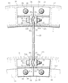
- FIG. 1 is a partial cross-sectional explanatory view of a front upper portion of a jet engine that employs a blade connecting portion structure according to an embodiment of the present invention. It is sectional explanatory drawing in the connection part of the wing
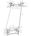
- FIG. 3 is an enlarged cross-sectional explanatory diagram of a blade base end portion of a connecting portion of the blade shown in FIG. It is side surface explanatory drawing of the connection part of the wing
- FIG. 1 to 4 show an embodiment of a blade connecting portion structure according to the present invention.
- a guide vane connecting portion as a stationary blade constituting a jet engine will be described as an example. .
- annular core channel 4 is formed on the axial center side of the engine inner cylinder 3 in the engine body 2, and an inner peripheral surface of a fan case 5 that is an outer portion of the engine body 2.
- bypass flow path 6 is formed between the outer peripheral surfaces of the engine inner cylinder 3.
- a fan disk 7 is installed at the front portion on the left side of the jet engine 1 in the drawing so as to be rotatable around an engine axis (not shown) via a bearing 8.
- the fan disk 7 is integrally connected to a turbine rotor in a low-pressure turbine (not shown) disposed at the rear right side of the jet engine 1 in the drawing.
- a plurality of moving blades 10 are arranged on the outer peripheral surface of the fan disk 7 at equal intervals in the circumferential direction via the fitting grooves 7a, before and after the moving blades 10 and the fitting grooves 7a.
- annular retainers 12 and 13 for supporting the moving blade 10 are integrally installed in the circumferential direction, and the front retainer 12 is integrally connected to the nose cone 14,
- the retainer 13 is coaxially and integrally connected to the rotor 16 in the low-pressure compressor 15 adjacent to the downstream side of the fan disk 7.
- a tip shroud for preventing vibration and improving aerodynamic performance is connected between the tips of the plurality of rotor blades 10, but this tip shroud is not shown in FIG.
- air can be introduced into the core flow path 4 and the bypass flow path 6 by rotating the plurality of moving blades 10 together with the fan disk 7.
- the jet engine 1 includes a plurality of guide vanes (static blades) 20 on the bypass flow path 6.
- the plurality of guide vanes 20 are arranged at equal intervals around the engine inner cylinder 3 so as to rectify the swirling air flow flowing through the bypass flow path 6.
- This guide vane 20 is made of a thermosetting resin such as an epoxy resin, a phenol resin, or a polyimide resin, or a thermoplastic resin such as polyetherimide, polyether ether ketone, or polyphenylene sulfide, and carbon fiber, aramid fiber, glass fiber, or the like.
- a composite material with reinforcing fibers is used as a constituent material, for example, laminated in the blade thickness direction or three-dimensionally woven.
- a blade base end portion (blade end portion) 21 on the axial center side of the guide vane 20 is connected to a mounting flange 31f of the fan frame 31 disposed in the engine inner cylinder 3, and is a side away from the axial center of the guide vane 20.
- the blade tip (blade tip) 22 is connected to a mounting flange 5 f arranged in the fan case 5.
- connection support body 33 comprising a pair of divided pieces 34 and 34 joined from both sides in the blade thickness direction (left and right direction in FIG. 2) is disposed.
- the split pieces 34, 34 of the connection support body 33 are both made of a metal such as an aluminum alloy or a titanium alloy, and are attached to the attachment flange 31f by bolts 38 and nuts 39.
- Opposite walls 35 facing each other are formed on the pair of divided pieces 34, 34 of the connection support body 33, and the opposing walls 35, 35 are formed on the blade base end portion 21 of the guide vane 20. It joins from both directions.
- the divided piece 34 on the left side in FIG. 2 that is, the end joint surface 35 a of the facing wall 35 in the divided piece 34 on the left side in FIG.
- a groove 35b having a trapezoidal cross section is formed in the direction of the engine axis.
- the right divided piece 34 in FIG. A protrusion 35c having a trapezoidal cross section is formed on the end joint surface 35a of the opposing wall 35 of the piece 34 so as to face the groove 35b.
- the blade base end portion 21 of the guide vane 20 is formed in a concavo-convex shape with a constant blade thickness in the engine radial direction, and the joint surface at the blade base end portion 21 of the guide vane 20.
- 21a and 21a are provided with a protrusion 21b that engages with a groove 35b formed on an end joint surface 35a of the split piece 34 on the left side of FIG. 2 on the joint surface 21a on the left side of FIG. , 21a on the right side of the joint surface 21a in FIG. 2 and on the back side of the projection 21b on the joint surface 21a on the left side of FIG. 2, the ridge formed on the end joint surface 35a of the split piece 34 on the right side of FIG.
- a groove 21c that engages with 35c is formed.
- the blade base end portion 21 of the guide vane 20 is paired by a fastening force by a bolt 36 and a nut 37 applied to the pair of split pieces 34, 34 of the connection support body 33 from both sides in the blade thickness direction. It is held between the opposing walls 35 and 35 of the divided pieces 34 and 34.
- connection support body 53 which consists of a pair of division
- Both of the divided pieces 54 and 54 of the connection support body 53 are made of a metal such as an aluminum alloy or a titanium alloy, and are attached to the attachment flange 5f by bolts 38 and nuts 39.
- the pair of divided pieces 54 and 54 of the connection support body 53 are also formed with opposing walls 55 that face each other, and these opposing walls 55 and 55 are formed in the blade thickness direction at the blade tip portion 22 of the guide vane 20. It is designed to be joined from both sides.
- the two divided pieces 54, 54 constituting the connection support body 53 are divided into the divided pieces 54 on the left side in FIG. 2, that is, the ends of the opposing walls 55 in the divided pieces 54 on the left side in FIG.
- One groove 55b having a trapezoidal cross section is formed on the joint surface 55a in the engine axial direction.
- the right divided piece 54 in FIG. 2 A protrusion 55c having a trapezoidal cross section is formed on the end joint surface 55a of the opposing wall 55 of the right split piece 54 so as to face the groove 55b.
- the blade tip 22 of the guide vane 20 is also formed in a concavo-convex shape with a constant blade thickness in the radial direction of the engine.
- the joining surface 22a is formed with a protrusion 22b that engages with the groove 55b formed in the end joining surface 55a of the split piece 54 on the left side of FIG. 2, and the joining surface 22a on the right side of FIG.
- a groove 22c that engages with the protrusion 55c formed on the end joining surface 55a of the split piece 54 on the right side of FIG. 2 is formed on the back surface of the protrusion 22b on the joining surface 22a on the left side of FIG. Has been.
- the blade tip 22 of the guide vane 20 has a pair of split pieces 54, 54 that are applied to the pair of split pieces 54, 54 of the connection support body 53 from both sides of the blade thickness direction by fastening force of bolts 56 and nuts 57. It is held between the opposing walls 55 and 55.
- the opposing walls 55 and 55 of the pair of split pieces 54 and 54 of the connection support body 53 and the blade tip portion 22 of the guide vane 20 held between the opposing walls 55 and 55 are also provided.
- An adhesive is interposed between the two.
- the blade base end portion 21 of the guide vane 20 made of the composite material is paired with the connection support body 33 made of metal. Between the opposing walls 35 and 35 of the divided pieces 34 and 34.
- the ridge 21b formed on the joint surface 21a on the left side in FIG. 2 of the blade base end portion 21 is engaged with the groove 35b formed on the joint surface 35a on the left side in FIG.
- the groove 21c formed on the joint surface 21a on the right side of FIG. 2 is engaged with the protrusion 35c formed on the joint surface 35a on the right side of FIG.
- the blade tip 22 of the guide vane 20 is positioned between the opposing walls 55 and 55 of the pair of split pieces 54 and 54 in the connection support body 53 made of metal. Further, the protrusion 22b formed on the joint surface 22a on the left side in FIG. 2 of the blade tip 22 is engaged with the groove 55b formed on the joint surface 55a on the left side in FIG. 2 A groove 22c formed on the right joint surface 22a is engaged with a protrusion 55c formed on the joint surface 55a on the right side of FIG.
- the connecting strength becomes a mechanical connecting strength. For example, process management at the connecting portion is facilitated as compared to the connecting strength using only the adhesive.
- the blade base end portion 21 (blade tip portion 22) is sandwiched between the opposing walls 35, 35 (55, 55) of the pair of split pieces 34, 34 (54, 54) from both sides in the blade thickness direction. Therefore, compared with the case where the blade base end portion 21 (blade tip portion 22) is cantilevered by one wall, for example, the bending of the blade base end portion 21 (blade tip portion 22) can be avoided. As a result, a strong connected state can be maintained.
- the groove 21c (22c) and the protrusion 21b (22b) on the blade base end portion 21 (blade tip portion 22) side are provided.
- ) Are respectively engaged with the protrusions 35c (55c) and the grooves 35b (55b) on the connection support body 33 (53) side, whereby the mutual positioning of the two is achieved. Will be illustrated.
- the blade base end portion 21 (blade tip portion 22) is formed in an uneven shape while keeping the blade thickness constant in the radial direction of the engine, that is, the blade base end portion 21 (blade tip portion 22). Since the groove 21c (22c) and the ridge 21b (22b) on the side are formed of continuous fibers, the strength can be maintained or improved without increasing the number of man-hours.
- the blade since the blade is the guide vane 20 as the stationary blade of the jet engine 1, the original rectifying function of the guide vane 20 is exhibited.
- jet engine 1 since the jet engine 1 according to this embodiment employs the above-described wing connection structure, both weight reduction and high strength can be realized.
- the blade connecting portion structure according to the present invention is adopted as the blade connecting portion of a guide vane as a stationary blade of a jet engine has been described as an example, but the present invention is not limited thereto.
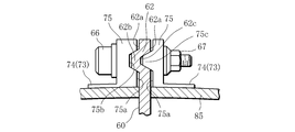
- a tip (blade tip) 62 of a moving blade 60 in a jet engine and a tip shroud that is provided on the tip 62 to prevent vibration and improve aerodynamic performance and rotate together with the moving blade 60. It is also possible to employ the connecting portion with 85.
- a groove 75b having a trapezoidal cross section is formed on the joint surface 75a on the left side of FIG. 5 of the joint surfaces 75a and 75a of the pair of split pieces 74 and 74 of the connection support body 73.
- a protrusion 75c is formed on the joining surface 75a on the right side in FIG. 5 so as to face the groove 75b.
- the tip 62 of the rotor blade 60 is formed in an uneven shape, and of the joint surfaces 62a and 62a of the tip 62 of the rotor blade 60, the joint surface 62a on the left side in FIG. 5 is formed on the joining surface 62a on the right side in FIG. 5 of the joining surfaces 62a and 62a.
- a groove 62c that engages with the ridge 75c formed in 75a is formed.
- the ridges 21b, 22b, 62b and the grooves 21c, 22c, 62c on the blade tip side, and the grooves 35b, 55b, 75b and the ridges 35c, 55c, 75c on the connection support body side are not limited to this, and as the ridges and grooves, those having a semicircular cross section, those having a triangular shape, and those having a rectangular shape are adopted. can do.
- the ridges 21b, 22b, 62b and the grooves 21c, 22c, 62c on the blade tip side, and the grooves 35b, 55b, 75b and the ridges 35c, 55c, 75c on the connection support body side are provided.
- the structure of the wing connecting portion and the jet engine according to the present invention is not limited to the above-described embodiments.
Landscapes
- Engineering & Computer Science (AREA)
- Mechanical Engineering (AREA)
- General Engineering & Computer Science (AREA)
- Chemical & Material Sciences (AREA)
- Materials Engineering (AREA)
- Combustion & Propulsion (AREA)
- Composite Materials (AREA)
- Structures Of Non-Positive Displacement Pumps (AREA)
- Lining Or Joining Of Plastics Or The Like (AREA)
- Turbine Rotor Nozzle Sealing (AREA)
Description
一方、ガイドベーンに整流機能に加えて構造体機能も持たせる場合には、ガイドベーンにアルミ合金等の金属材料を構成材料として用いる都合上、ストラットを用いる場合と同じく航空機ジェットエンジンの軽量化の妨げになるという問題があり、これを解決することが従来の課題となっている。
好ましくは、前記翼が前記ジェットエンジンの静翼である構成とする。
図1~図4は本発明に係る翼の連結部構造の一実施例を示しており、この実施例では、ジェットエンジンを構成する静翼としてのガイドベーンの連結部を例に挙げて説明する。
なお、複数の動翼10の各チップ間には、振動防止及び空力性能改善のためのチップシュラウドが連結されているが、このチップシュラウドは図1において図示していない。
20 ガイドベーン(静翼)
21 翼基端部(翼端部)
21a,22a,62a 接合面
21b,22b,62b 突条
21c,22c,62c 溝
22 翼先端部(翼端部)
33,53,73 連結サポート体
34,54,74 一対の分割片
35a,55a,75a 端部接合面
35b,55b,75b 溝
35c,55c,75c 突条
36 ボルト
37 ナット
60 動翼
62 チップ(翼先端部)
Claims (4)
- ジェットエンジンを構成する熱硬化性樹脂又は熱可塑性樹脂と強化繊維との複合材料から成る翼の連結部構造であって、
前記翼連結部には、前記翼の端部に対して翼厚方向両側から接合する互いに分割された一対の分割片を有する金属から成る連結サポート体が配置され、
前記連結サポート体の一対の分割片における各端部接合面のうちのいずれか一方の端部接合面には、突条が前記ジェットエンジンの軸心方向に形成されていると共に、いずれか他方の端部接合面には、溝が前記ジェットエンジンの軸心方向に前記突条と対向して形成され、
前記翼の端部は前記ジェットエンジンの径方向に翼厚一定状態で凹凸状に形成されて、該翼の端部は、前記一対の分割片との接合面のうちのいずれか一方の接合面に前記一対の分割片のいずれか一方の端部接合面に形成された前記突条と係合する溝を有していると共に、いずれか他方の接合面で且つ前記いずれか一方の接合面における溝の裏側位置に前記一対の分割片のいずれか他方の端部接合面に形成された前記溝と係合する突条を有し、
前記翼の端部は、前記連結サポート体の一対の分割片に翼厚方向両側から付与される締結力により該連結サポート体の一対の分割片間に保持されている
ことを特徴とする翼の連結部構造。 - 前記連結サポート体の一対の分割片と、該一対の分割片間に保持される前記翼の端部との間に接着剤が介在されている請求項1に記載の翼の連結部構造。
- 前記翼が前記ジェットエンジンの静翼である請求項1又は2に記載の翼の連結部構造。
- ジェットエンジンを構成する翼の連結部構造として請求項1~3のいずれか一つの項に記載の翼の連結部構造が用いられている
ことを特徴とするジェットエンジン。
Priority Applications (5)
| Application Number | Priority Date | Filing Date | Title |
|---|---|---|---|
| EP13806092.6A EP2865879B1 (en) | 2012-06-20 | 2013-06-19 | Vane linking portion structure, and jet engine using same |
| CN201380023301.XA CN104334863B (zh) | 2012-06-20 | 2013-06-19 | 叶片的连结部结构及使用该连结部结构的喷气式发动机 |
| CA2871842A CA2871842C (en) | 2012-06-20 | 2013-06-19 | Coupling part structure for vane and jet engine including the same |
| RU2015101531/06A RU2601696C2 (ru) | 2012-06-20 | 2013-06-19 | Присоединяющая лопатку конструкция и реактивный двигатель, содержащий данную конструкцию |
| US14/398,360 US9896963B2 (en) | 2012-06-20 | 2014-10-31 | Coupling part structure for vane and jet engine including the same |
Applications Claiming Priority (2)
| Application Number | Priority Date | Filing Date | Title |
|---|---|---|---|
| JP2012138655A JP6082193B2 (ja) | 2012-06-20 | 2012-06-20 | 翼の連結部構造及びこれを用いたジェットエンジン |
| JP2012-138655 | 2012-06-20 |
Related Child Applications (1)
| Application Number | Title | Priority Date | Filing Date |
|---|---|---|---|
| US14/398,360 Continuation US9896963B2 (en) | 2012-06-20 | 2014-10-31 | Coupling part structure for vane and jet engine including the same |
Publications (1)
| Publication Number | Publication Date |
|---|---|
| WO2013191195A1 true WO2013191195A1 (ja) | 2013-12-27 |
Family
ID=49768789
Family Applications (1)
| Application Number | Title | Priority Date | Filing Date |
|---|---|---|---|
| PCT/JP2013/066786 Ceased WO2013191195A1 (ja) | 2012-06-20 | 2013-06-19 | 翼の連結部構造及びこれを用いたジェットエンジン |
Country Status (7)
| Country | Link |
|---|---|
| US (1) | US9896963B2 (ja) |
| EP (1) | EP2865879B1 (ja) |
| JP (1) | JP6082193B2 (ja) |
| CN (1) | CN104334863B (ja) |
| CA (1) | CA2871842C (ja) |
| RU (1) | RU2601696C2 (ja) |
| WO (1) | WO2013191195A1 (ja) |
Families Citing this family (4)
| Publication number | Priority date | Publication date | Assignee | Title |
|---|---|---|---|---|
| JP6612161B2 (ja) * | 2016-03-24 | 2019-11-27 | 川崎重工業株式会社 | タービンの支持構造 |
| FR3064671B1 (fr) * | 2017-03-29 | 2020-09-25 | Safran Aircraft Engines | Bras de liaison d'une turbomachine muni d'un element de retenue de cale |
| US11065825B2 (en) * | 2018-12-05 | 2021-07-20 | Raytheon Technologies Corporation | High temperature composite seal |
| JP7120913B2 (ja) * | 2018-12-25 | 2022-08-17 | 三菱重工業株式会社 | ガスタービン排気車室及びガスタービン |
Citations (7)
| Publication number | Priority date | Publication date | Assignee | Title |
|---|---|---|---|---|
| JPH0444404U (ja) * | 1990-08-14 | 1992-04-15 | ||
| JPH05149148A (ja) | 1991-05-28 | 1993-06-15 | General Electric Co <Ge> | コアフレームを静翼フレームに安定中央リングで着脱自在に取付ける装置 |
| US5320490A (en) | 1991-12-18 | 1994-06-14 | Societe Nationale D'etude Et De Construction De Moteurs D'aviation "S.N.E.C.M.A." | Structural arm of the casing of a turbo-engine |
| JPH08246804A (ja) * | 1995-03-06 | 1996-09-24 | Solar Turbines Inc | 改良されたノズル及びシュラウド組み立て体取付構造 |
| JP2766423B2 (ja) | 1991-05-28 | 1998-06-18 | ゼネラル・エレクトリック・カンパニイ | 取り外し可能なターボファン・エンジン組立体 |
| JP2008534837A (ja) * | 2005-03-24 | 2008-08-28 | アルストム テクノロジー リミテッド | ターボ機械のためのダイアフラム及び翼 |
| WO2008121047A1 (en) * | 2007-03-30 | 2008-10-09 | Volvo Aero Corporation | A gas turbine engine component, a turbojet engine provided therewith, and an aircraft provided therewith |
Family Cites Families (20)
| Publication number | Priority date | Publication date | Assignee | Title |
|---|---|---|---|---|
| US5272869A (en) * | 1992-12-10 | 1993-12-28 | General Electric Company | Turbine frame |
| CA2231986A1 (en) * | 1997-01-10 | 1999-09-12 | Masahito Kataoka | Stationary blade of integrated segment construction and manufacturing method therefor |
| JP4040922B2 (ja) * | 2001-07-19 | 2008-01-30 | 株式会社東芝 | 組立式ノズルダイアフラムおよびその組立方法 |
| US6761807B2 (en) * | 2002-03-09 | 2004-07-13 | United Technologies Corporation | Molded tooling for use in airfoil stripping processes |
| US6908279B2 (en) * | 2003-11-25 | 2005-06-21 | General Electric Company | Method of installing stationary blades of a turbine and turbine structure having a radial loading pin |
| EP1548233B1 (fr) * | 2003-12-18 | 2006-08-02 | Techspace Aero S.A. | Dispositif de fixation d'aubes à une virole et étage redresseur de compresseur comportant un tel dispositif |
| RU40655U1 (ru) * | 2004-04-05 | 2004-09-20 | Открытое акционерное общество "Научно-производственное объединение "Сатурн" | Стоечный узел двигателя |
| SE528948C2 (sv) * | 2004-12-23 | 2007-03-20 | Volvo Aero Corp | Ringformad vridstyv statisk komponent för en flygplansmotor |
| US8079773B2 (en) | 2005-10-18 | 2011-12-20 | General Electric Company | Methods and apparatus for assembling composite structures |
| US8061977B2 (en) * | 2007-07-03 | 2011-11-22 | Siemens Energy, Inc. | Ceramic matrix composite attachment apparatus and method |
| US7609465B2 (en) * | 2008-03-05 | 2009-10-27 | Tdk Taiwan Corporation | EMI-proof miniature lens focusing mechanism |
| EP2321499B1 (en) * | 2008-08-29 | 2017-12-13 | GKN Aerospace Sweden AB | A component and a gas turbine engine comprising the component |
| US8251651B2 (en) * | 2009-01-28 | 2012-08-28 | United Technologies Corporation | Segmented ceramic matrix composite turbine airfoil component |
| FR2941487B1 (fr) * | 2009-01-28 | 2011-03-04 | Snecma | Aube de turbomachine en materiau composite a pied renforce |
| US8070429B2 (en) * | 2009-03-11 | 2011-12-06 | General Electric Company | Turbine singlet nozzle assembly with mechanical and weld fabrication |
| US8226361B2 (en) * | 2009-07-08 | 2012-07-24 | General Electric Company | Composite article and support frame assembly |
| FR2958680B1 (fr) * | 2010-04-13 | 2015-08-14 | Snecma | Carter intermediaire de turboreacteur multi-flux |
| FR2961847B1 (fr) * | 2010-06-25 | 2012-08-17 | Snecma | Roue mobile a aubes en materiau composite pour moteur a turbine a gaz a liaison pied d'aube/disque par serrage |
| US8734101B2 (en) * | 2010-08-31 | 2014-05-27 | General Electric Co. | Composite vane mounting |
| FR3006368B1 (fr) * | 2013-05-28 | 2015-07-03 | Herakles | Aube de disque de rotor avec retenue du pied par frottement |
-
2012
- 2012-06-20 JP JP2012138655A patent/JP6082193B2/ja not_active Expired - Fee Related
-
2013
- 2013-06-19 WO PCT/JP2013/066786 patent/WO2013191195A1/ja not_active Ceased
- 2013-06-19 CA CA2871842A patent/CA2871842C/en active Active
- 2013-06-19 RU RU2015101531/06A patent/RU2601696C2/ru active
- 2013-06-19 CN CN201380023301.XA patent/CN104334863B/zh not_active Expired - Fee Related
- 2013-06-19 EP EP13806092.6A patent/EP2865879B1/en active Active
-
2014
- 2014-10-31 US US14/398,360 patent/US9896963B2/en active Active
Patent Citations (7)
| Publication number | Priority date | Publication date | Assignee | Title |
|---|---|---|---|---|
| JPH0444404U (ja) * | 1990-08-14 | 1992-04-15 | ||
| JPH05149148A (ja) | 1991-05-28 | 1993-06-15 | General Electric Co <Ge> | コアフレームを静翼フレームに安定中央リングで着脱自在に取付ける装置 |
| JP2766423B2 (ja) | 1991-05-28 | 1998-06-18 | ゼネラル・エレクトリック・カンパニイ | 取り外し可能なターボファン・エンジン組立体 |
| US5320490A (en) | 1991-12-18 | 1994-06-14 | Societe Nationale D'etude Et De Construction De Moteurs D'aviation "S.N.E.C.M.A." | Structural arm of the casing of a turbo-engine |
| JPH08246804A (ja) * | 1995-03-06 | 1996-09-24 | Solar Turbines Inc | 改良されたノズル及びシュラウド組み立て体取付構造 |
| JP2008534837A (ja) * | 2005-03-24 | 2008-08-28 | アルストム テクノロジー リミテッド | ターボ機械のためのダイアフラム及び翼 |
| WO2008121047A1 (en) * | 2007-03-30 | 2008-10-09 | Volvo Aero Corporation | A gas turbine engine component, a turbojet engine provided therewith, and an aircraft provided therewith |
Non-Patent Citations (1)
| Title |
|---|
| See also references of EP2865879A4 |
Also Published As
| Publication number | Publication date |
|---|---|
| CA2871842C (en) | 2018-03-06 |
| US9896963B2 (en) | 2018-02-20 |
| JP6082193B2 (ja) | 2017-02-15 |
| CN104334863B (zh) | 2016-09-07 |
| EP2865879B1 (en) | 2018-10-31 |
| CN104334863A (zh) | 2015-02-04 |
| CA2871842A1 (en) | 2013-12-27 |
| EP2865879A4 (en) | 2016-03-02 |
| RU2015101531A (ru) | 2016-08-10 |
| EP2865879A1 (en) | 2015-04-29 |
| RU2601696C2 (ru) | 2016-11-10 |
| JP2014001708A (ja) | 2014-01-09 |
| US20150132118A1 (en) | 2015-05-14 |
Similar Documents
| Publication | Publication Date | Title |
|---|---|---|
| JP5962887B2 (ja) | 翼の連結部構造及びこれを用いたジェットエンジン | |
| RU2554381C2 (ru) | Крепежная конструкция направляющих лопастей и вентилятор | |
| CA2725238C (en) | Architecture of a compressor rectifier | |
| EP2199544B1 (fr) | Architecture de redresseur | |
| JP6082193B2 (ja) | 翼の連結部構造及びこれを用いたジェットエンジン | |
| US9739163B2 (en) | Strip for abradable in a compressor turbine | |
| CN108868902A (zh) | 具有共同结合复合材料和金属环的部件及其组装方法 | |
| CN105874169B (zh) | 叶片的连结部构造以及使用该叶片的连结部构造的喷气式发动机 | |
| WO2016056463A1 (ja) | 静翼構造及びこれを用いたターボファンエンジン | |
| US10710317B2 (en) | Composite rotatable assembly for an axial-flow compressor | |
| JP2024017167A (ja) | 回転機械用ディスク、及び回転機械 | |
| JP2016035247A (ja) | 遠心圧縮機 |
Legal Events
| Date | Code | Title | Description |
|---|---|---|---|
| 121 | Ep: the epo has been informed by wipo that ep was designated in this application |
Ref document number: 13806092 Country of ref document: EP Kind code of ref document: A1 |
|
| ENP | Entry into the national phase |
Ref document number: 2871842 Country of ref document: CA |
|
| WWE | Wipo information: entry into national phase |
Ref document number: 2013806092 Country of ref document: EP |
|
| NENP | Non-entry into the national phase |
Ref country code: DE |
|
| ENP | Entry into the national phase |
Ref document number: 2015101531 Country of ref document: RU Kind code of ref document: A |