WO2013191327A1 - 쾌속 충전이 가능한 데이터 케이블 - Google Patents
쾌속 충전이 가능한 데이터 케이블 Download PDFInfo
- Publication number
- WO2013191327A1 WO2013191327A1 PCT/KR2012/007522 KR2012007522W WO2013191327A1 WO 2013191327 A1 WO2013191327 A1 WO 2013191327A1 KR 2012007522 W KR2012007522 W KR 2012007522W WO 2013191327 A1 WO2013191327 A1 WO 2013191327A1
- Authority
- WO
- WIPO (PCT)
- Prior art keywords
- terminal
- mode switching
- usb
- mode
- cable
- Prior art date
- Legal status (The legal status is an assumption and is not a legal conclusion. Google has not performed a legal analysis and makes no representation as to the accuracy of the status listed.)
- Ceased
Links
Images



Classifications
-
- H—ELECTRICITY
- H01—ELECTRIC ELEMENTS
- H01R—ELECTRICALLY-CONDUCTIVE CONNECTIONS; STRUCTURAL ASSOCIATIONS OF A PLURALITY OF MUTUALLY-INSULATED ELECTRICAL CONNECTING ELEMENTS; COUPLING DEVICES; CURRENT COLLECTORS
- H01R31/00—Coupling parts supported only by co-operation with counterpart
- H01R31/06—Intermediate parts for linking two coupling parts, e.g. adapter
-
- H—ELECTRICITY
- H01—ELECTRIC ELEMENTS
- H01R—ELECTRICALLY-CONDUCTIVE CONNECTIONS; STRUCTURAL ASSOCIATIONS OF A PLURALITY OF MUTUALLY-INSULATED ELECTRICAL CONNECTING ELEMENTS; COUPLING DEVICES; CURRENT COLLECTORS
- H01R13/00—Details of coupling devices of the kinds covered by groups H01R12/70 or H01R24/00 - H01R33/00
- H01R13/66—Structural association with built-in electrical component
- H01R13/70—Structural association with built-in electrical component with built-in switch
-
- H—ELECTRICITY
- H02—GENERATION; CONVERSION OR DISTRIBUTION OF ELECTRIC POWER
- H02J—ELECTRIC POWER NETWORKS; CIRCUIT ARRANGEMENTS OR SYSTEMS FOR SUPPLYING OR DISTRIBUTING ELECTRIC POWER; SYSTEMS FOR STORING ELECTRIC ENERGY
- H02J7/00—Circuit arrangements for charging or discharging batteries or for supplying loads from batteries
- H02J7/70—Circuit arrangements for charging or discharging batteries or for supplying loads from batteries characterised by the mechanical construction
- H02J7/731—Circuit arrangements for charging or discharging batteries or for supplying loads from batteries characterised by the mechanical construction specially adapted for holding portable devices containing batteries
-
- H—ELECTRICITY
- H01—ELECTRIC ELEMENTS
- H01R—ELECTRICALLY-CONDUCTIVE CONNECTIONS; STRUCTURAL ASSOCIATIONS OF A PLURALITY OF MUTUALLY-INSULATED ELECTRICAL CONNECTING ELEMENTS; COUPLING DEVICES; CURRENT COLLECTORS
- H01R29/00—Coupling parts for selective co-operation with a counterpart in different ways to establish different circuits, e.g. for voltage selection, for series-parallel selection, programmable connectors
-
- H—ELECTRICITY
- H01—ELECTRIC ELEMENTS
- H01R—ELECTRICALLY-CONDUCTIVE CONNECTIONS; STRUCTURAL ASSOCIATIONS OF A PLURALITY OF MUTUALLY-INSULATED ELECTRICAL CONNECTING ELEMENTS; COUPLING DEVICES; CURRENT COLLECTORS
- H01R31/00—Coupling parts supported only by co-operation with counterpart
- H01R31/06—Intermediate parts for linking two coupling parts, e.g. adapter
- H01R31/065—Intermediate parts for linking two coupling parts, e.g. adapter with built-in electric apparatus
-
- H—ELECTRICITY
- H02—GENERATION; CONVERSION OR DISTRIBUTION OF ELECTRIC POWER
- H02J—ELECTRIC POWER NETWORKS; CIRCUIT ARRANGEMENTS OR SYSTEMS FOR SUPPLYING OR DISTRIBUTING ELECTRIC POWER; SYSTEMS FOR STORING ELECTRIC ENERGY
- H02J7/00—Circuit arrangements for charging or discharging batteries or for supplying loads from batteries
Definitions
- the present invention relates to a data communication cable of a terminal, and more particularly to a USB data cable used for data transmission and / or charging between a terminal and a PC with a built-in secondary battery using a USB port.
- a type of communication port mainly used for data transmission includes a universal asynchronous receiver transmitter (UART) and a universal serial bus (USB).
- UART universal asynchronous receiver transmitter
- USB universal serial bus
- a UART is a device that handles asynchronous serial communications. Every computer has a UART to manage its serial port, and every internal modem has its own UART. In more detail, the UART provides a computer with an RS-232C interface that allows it to communicate with or send data to a modem or other serial device.
- USB is a peripheral interface specification jointly proposed by seven companies including IBM, and aims to jointly interface for connecting various peripheral devices to a personal computer.
- RS-232C Recommended Standard-232C
- USB port the charging time is longer compared with charging using a dedicated adapter which is a DC converter.
- USB data cable In the technology related to charging using a USB data cable, conventionally a USB data cable that automatically detects the type of power supply to prevent overcharging, and a USB data cable that can arbitrarily set a charging time to prevent overcharging, and DC conversion.
- a USB data cable connected to a dedicated adapter which is a device
- the charging time is very long for charging using a USB terminal of a PC, which is inconvenient in using a terminal.
- a dedicated adapter In the case of a USB data cable connected to the adapter, a dedicated adapter Inconvenient in terms of portability because it must carry.
- An object of the present invention is to connect a terminal to a USB terminal of a PC using a USB data cable, and in the case of data transmission and / or charging, providing a technology for enabling fast charging by switching to a charge-only mode after completing data transmission. It is.
- the data cable capable of fast charging according to the present invention for achieving the above object the cable for data transmission and charging, the first connection portion provided to be connected to the power supply at either end of the cable, the cable And a mode switch circuit for enabling a mode switch between a data transmission and quick charge mode, the second connector being provided to be connected to the mobile terminal at the other end of the mode switch, wherein the mode switch circuit comprises: an input voltage of the first connector; And a terminal switching logic for applying a switch, a distribution resistor, a switch for mode switching between the data transfer and quick charge mode, and an analog switching logic responsive to the switch for switching.
- the power supply of the first connection portion is a USB terminal of the PC
- the second connection portion is a USB connector
- the terminal for applying the input voltage is a USB VBUS terminal
- the distribution resistor is USB D +
- the distribution resistors associated with the terminal and the USB D- terminal are preferred.
- the mode switching circuit and the mode switching switch may be configured by distribution resistors differently set for each mobile terminal provider with respect to the USB D + terminal and the USB D- terminal recognition. It is preferable that the mode is a general mode switching circuit and a mode switching switch capable of selecting the fast charging mode for each terminal provider.
- the mode switching circuit and the mode switching switch are for mode switching by a specified distribution resistor of the mobile terminal provider with respect to the USB D + terminal and the USB D- terminal recognition. It is preferable that this is a mode switching circuit and a mode switching switch dedicated to the terminal provider.
- the position of the mode switching circuit and the mode switching switch is located at any one of the first connecting portion, the second connecting portion, or the cable.
- a data cable capable of fast charging has the following effects.
- the mode switching switch that can switch the mode between the data transfer mode and the fast charge mode enables data transfer in the data transfer mode while charging less than 500mAh, and fast charge mode can be faster than 500mAh Therefore, the charging time is shortened in the charging of a terminal having a large capacity battery.
- the mode switch can be integrated with the USB data cable to increase usability and mobility.
- FIG. 1 is a perspective view of a USB data cable according to an embodiment according to the present invention.
- FIG. 2 is a cross-sectional view of the terminal when the second connection unit according to an embodiment of the present invention is a 5-pin Micro-USB terminal.
- FIG 3 shows a mode switching switch on a first connection part and a mode switching circuit inside the first connection part according to an embodiment according to the present invention.
- Figure 4 shows the position of the mode switch for switching according to the embodiment of the present invention.
- the USB data cable includes a first connection unit 110, a cable 120 for data and charging purposes, a second connection unit 130, and a mode switching switch 140.
- the first connector 110 corresponds to a USB terminal when the USB terminal of the PC is used as a power source as a part connected to the power source.
- the mode switching switch 140 is located on the first connection part in a simplified manner, and a mode switching circuit (not shown) is also located inside the first connection part. Mode switching switch 140 dedicated to a specific terminal of the terminal provider is provided to select any one of charging and data transmission.
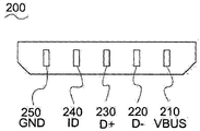
- FIG. 2 is a diagram illustrating a terminal cross section when the second connector is a 5-pin Micro-USB terminal as one embodiment according to the present invention.
- a reference voltage of 5V comes out as an output value from the first connection portion and is applied to the input of the terminal connected to the second connection portion through an intermediate cable.
- the second terminal, the D- terminal and the third terminal, the D + terminal correspond to the data transmission terminal of the USB data cable, and in the quick charge mode with respect to the distribution resistance of the terminal provider, the D + terminal and the D- terminal are open or shorted.
- the portable terminal connected to the second connector recognizes that the charging adapter is connected to the first connector.
- the fourth terminal corresponds to the ID terminal. In relation to the mechanism of the ID terminal, the ID terminal operates in accordance with Battery Charging Specification Revision 1.2.
- the last terminal, the GND terminal 250 corresponds to the ground terminal.
- FIG. 3 is an enlarged view of a perspective view of a USB data cable of the present invention and a mode switching circuit 300 between the first connection part and the cable as one embodiment according to the present invention.
- the USB connector part corresponds to an embodiment of the first connection part, and the USB terminal of the PC is preferably connected.
- the USB terminal of the PC is preferably connected.
- the end of the USB cable 320 will follow a second connection, although not shown in FIG. 3.
- all of the above switching circuits and mode switching switches are located in the first connector USB connector, according to an embodiment of the present invention. As described above, it may be located close to the power supply, and may be located on the data cable (Fig. 4) like the volume control lever of the earphone, and is located on the connector of the second connection part close to the terminal connected to the second connection part (Fig. 4) You can also.
- the VBUS terminal is shown at the top of the four terminals.
- 5 V power switching between the USB connector and the USB cable is performed.
- 5V switching logic is located to control the voltage.
- the GND terminal 324 is a ground terminal.
- the D- and D + terminals are for transferring data when the USB cable is in data transfer mode.
- the mode switching switch 140 of FIG. 1 is illustrated as a general purpose mode switching switch 360 in FIG. 3.
- the distribution resistors of each company are included in the mode switching circuit.
- the position of the selection point of the mode switching switch 360 may be any one of A, B, n, which means a mobile terminal provider, and data, which means data transmission. If it is in the position A, the D + terminal and the D- terminal of the A company's distribution resistor are shorted or opened to enter the fast charging mode of the portable terminal provided by the company A, which is connected to the second connection, and vice versa.
- n which means a provider of a portable terminal other than the above, it enters the fast charging mode of the portable terminal provided by the B company or the n company. If the selection point of the mode switch is in data, the USB data cable will be ready to transfer data.
- Figure 4 shows a case where the mode switch is located in the connector of the second connection (a) and in the middle of the cable (b).
- the data transfer mode and the quick charge mode can be automatically switched when a circuit for determining the transfer of data is built in place of all the switching switches.
Landscapes
- Engineering & Computer Science (AREA)
- Power Engineering (AREA)
- Charge And Discharge Circuits For Batteries Or The Like (AREA)
- Telephone Set Structure (AREA)
- Telephone Function (AREA)
Abstract
Description
Claims (5)
- 데이터 전송 및 충전 용도의 케이블;상기 케이블의 양단 중 한쪽 단에서 전원과 연결되기 위해서 마련되는 제 1 연결부;상기 케이블의 다른 쪽 단에서 휴대 단말기와 연결되기 위해서 마련되는 제 2 연결부; 및데이터 전송 및 쾌속 충전 모드 간의 모드 전환을 가능하게 하는 모드 전환 회로를 포함하되,상기 모드 전환 회로는,상기 제 1 연결부의 입력 전압을 인가하는 단자 스위칭 로직;분배 저항;상기 데이터 전송 및 쾌속 충전 모드 간의 모드 전환용 스위치; 및상기 전환용 스위치에 반응하는 아날로그 스위칭 로직을 포함하는 것을 특징으로 하는 쾌속 충전이 가능한 데이터 케이블.
- 제 1 항에 있어서,상기 제 1 연결부의 전원은 PC의 USB 단자, 상기 제 1 연결부는 USB 커넥터, 상기 입력 전압을 인가하는 단자는 USB VBUS 단자, 분배 저항은 USB D+ 단자 및 USB D- 단자 관련 분배저항인 것을 특징으로 하는 쾌속 충전이 가능한 데이터 케이블.
- 제 1항 또는 제 2 항에 있어서,상기 모드 전환 회로 및 모드 전환용 스위치는, 상기 USB D+ 단자 및 USB D- 단자 인식과 관련하여 상기 휴대 단말기 제공 업체별로 서로 다르게 설정된 분배 저항에 의한 쾌속 충전 모드 선택을 상기 단말기 제공 업체별로 할 수 있는 범용의 모드 전환 회로 및 모드 전환용 스위치인 것을 특징으로 하는 쾌속 충전이 가능한 데이터 케이블.
- 제 1 항 또는 제 2 항에 있어서,상기 모드 전환 회로 및 모드 전환용 스위치는, 상기 USB D+ 단자 및 USB D- 단자 인식과 관련하여 상기 휴대 단말기 제공 업체의 지정된 분배 저항에 의한 모드 전환이 가능한 상기 단말기 제공 업체 전용의 모드 전환 회로 및 모드 전환용 스위치인 것을 특징으로 하는 쾌속 충전이 가능한 데이터 케이블.
- 제 1 항 또는 제 2 항에 있어서,상기 모드 전환 회로 및 모드 전환용 스위치의 위치가 상기 제 1 연결부, 상기 제 2 연결부 또는 상기 케이블 중 어느 한 곳에 위치하는 것을 특징으로 하는 쾌속 충전이 가능한 데이터 케이블.
Priority Applications (4)
| Application Number | Priority Date | Filing Date | Title |
|---|---|---|---|
| US14/407,808 US9559534B2 (en) | 2012-06-21 | 2012-09-20 | Data cable for fast charging |
| CN201280074140.2A CN104508917B (zh) | 2012-06-21 | 2012-09-20 | 能够快速充电的数据电缆 |
| EP12879556.4A EP2866310A4 (en) | 2012-06-21 | 2012-09-20 | DATA CABLE FOR FAST LOADING |
| JP2015515922A JP5986304B2 (ja) | 2012-06-21 | 2012-09-20 | 急速充電可能なデータケーブル |
Applications Claiming Priority (2)
| Application Number | Priority Date | Filing Date | Title |
|---|---|---|---|
| KR20120066483A KR101278466B1 (ko) | 2012-06-21 | 2012-06-21 | 쾌속 충전이 가능한 데이터 케이블 |
| KR10-2012-0066483 | 2012-06-21 |
Publications (1)
| Publication Number | Publication Date |
|---|---|
| WO2013191327A1 true WO2013191327A1 (ko) | 2013-12-27 |
Family
ID=48996076
Family Applications (1)
| Application Number | Title | Priority Date | Filing Date |
|---|---|---|---|
| PCT/KR2012/007522 Ceased WO2013191327A1 (ko) | 2012-06-21 | 2012-09-20 | 쾌속 충전이 가능한 데이터 케이블 |
Country Status (6)
| Country | Link |
|---|---|
| US (1) | US9559534B2 (ko) |
| EP (1) | EP2866310A4 (ko) |
| JP (1) | JP5986304B2 (ko) |
| KR (1) | KR101278466B1 (ko) |
| CN (1) | CN104508917B (ko) |
| WO (1) | WO2013191327A1 (ko) |
Families Citing this family (19)
| Publication number | Priority date | Publication date | Assignee | Title |
|---|---|---|---|---|
| AU2013100194A4 (en) * | 2013-02-22 | 2013-04-04 | Global Shopping Network Pty Ltd | A Power Supply |
| KR101471452B1 (ko) * | 2014-02-05 | 2014-12-10 | (주)엠에이피테크 | 고속 충전이 가능한 듀얼 모드 충전 커넥터 |
| KR200479833Y1 (ko) * | 2014-02-20 | 2016-03-10 | 주식회사 코피아 | 접속 단말장치간 데이터 통신을 지원하는 지능형 충전장치 |
| CN104135057B (zh) * | 2014-08-13 | 2016-05-18 | 宇龙计算机通信科技(深圳)有限公司 | 终端、充电器和充电方法 |
| TWI616028B (zh) * | 2014-08-14 | 2018-02-21 | 新唐科技股份有限公司 | 晶片及具有晶片的傳輸裝置及其控制方法 |
| CN104836277A (zh) * | 2015-04-20 | 2015-08-12 | 江苏宏云技术有限公司 | 一种锂电池快充的通信方法 |
| CN106486851B (zh) * | 2015-08-28 | 2019-05-14 | 富士康(昆山)电脑接插件有限公司 | 线缆连接器组件 |
| CN105162213A (zh) * | 2015-10-15 | 2015-12-16 | 上海斐讯数据通信技术有限公司 | Usb控制装置及设备 |
| PL3214726T3 (pl) * | 2016-01-05 | 2019-04-30 | Guangdong Oppo Mobile Telecommunications Corp Ltd | Sposób szybkiego ładowania, terminal mobilny i zasilacz sieciowy |
| CN107085558B (zh) * | 2016-03-28 | 2020-12-04 | 曹巍 | 一种连接a型usb与c型usb设备的适配器 |
| CN105914547A (zh) * | 2016-05-25 | 2016-08-31 | 广东欧珀移动通信有限公司 | 一种数据线、充电装置及其智能识别切换otg的方法 |
| BR112019004054A2 (pt) | 2016-08-29 | 2019-05-21 | 3M Innovative Properties Company | protetor auditivo eletrônico com contatos elétricos chaveáveis |
| USD826866S1 (en) * | 2017-01-23 | 2018-08-28 | Fuse Chicken, Llc | Combined flexible docking cable and support for mobile device |
| CN109861038B (zh) * | 2018-12-11 | 2021-08-20 | 苏州佳世达电通有限公司 | 可自动切换连接模式的usb连接埠及其控制方法 |
| ES1232395Y (es) * | 2019-06-21 | 2019-10-07 | Bartosz Zygmunt Rogowiec | Interruptor de cable con cargador usb |
| CN111817384B (zh) * | 2020-07-14 | 2022-04-22 | 维沃移动通信有限公司 | 数据线和充电设备 |
| CN116131372A (zh) * | 2021-11-15 | 2023-05-16 | 广东小天才科技有限公司 | 充电电路及系统、可穿戴设备、可穿戴设备的充电方法 |
| CN118152315A (zh) * | 2022-12-06 | 2024-06-07 | 华为技术有限公司 | 一种电子设备及充电系统 |
| KR102774084B1 (ko) * | 2024-02-19 | 2025-03-04 | 주식회사 서울전기 | 다규격 연결 및 고속충전이 가능한 멀티탭장치 |
Citations (5)
| Publication number | Priority date | Publication date | Assignee | Title |
|---|---|---|---|---|
| JP3318554B2 (ja) * | 1999-03-25 | 2002-08-26 | ソースネクスト株式会社 | USB(UniversalSerialBus)ケーブル及びUSBケーブルによる外部装置への充電方法 |
| KR200352806Y1 (ko) * | 2004-03-26 | 2004-06-07 | 주식회사 유엠텍 | 다기능 유에스비 컨넥터 |
| KR200385821Y1 (ko) * | 2005-03-23 | 2005-06-02 | 아멘텍(주) | 양방향 유에스비 데이터 통신 케이블의 전원을 이용한충전장치 |
| KR20070056253A (ko) * | 2005-11-29 | 2007-06-04 | 엠텍비젼 주식회사 | Usb 케이블 장치 |
| JP2009163517A (ja) * | 2008-01-07 | 2009-07-23 | Ricoh Co Ltd | データ移行装置 |
Family Cites Families (12)
| Publication number | Priority date | Publication date | Assignee | Title |
|---|---|---|---|---|
| US6211649B1 (en) * | 1999-03-25 | 2001-04-03 | Sourcenext Corporation | USB cable and method for charging battery of external apparatus by using USB cable |
| JP2000284874A (ja) * | 1999-03-31 | 2000-10-13 | Mitsumi Electric Co Ltd | 変換コネクタ |
| US6465987B1 (en) * | 2000-10-17 | 2002-10-15 | Hewlett-Packard Company | Power source of peripheral devices |
| JP3079786U (ja) * | 2001-02-22 | 2001-08-31 | 株式会社レッツ・コーポレーション | 携帯電話機の接続ケーブル |
| JP3734448B2 (ja) * | 2002-01-18 | 2006-01-11 | パイオニア株式会社 | 充電ケーブル |
| JP2006262610A (ja) * | 2005-03-16 | 2006-09-28 | Mitsumi Electric Co Ltd | 電源回路 |
| JP2007103091A (ja) * | 2005-09-30 | 2007-04-19 | Ntt Docomo Inc | 接続ケーブル |
| KR101329307B1 (ko) * | 2007-01-25 | 2013-11-13 | 삼성전자주식회사 | Usb 동작을 제어하는 장치 및 방법 |
| US7501792B2 (en) * | 2007-03-14 | 2009-03-10 | Sony Ericsson Mobile Communications Ab | Charging cable with USB-like connector |
| US7581970B2 (en) * | 2007-11-16 | 2009-09-01 | Sony Ericsson Mobile Communications Ab | Multipurpose universal serial bus cable |
| TWM412534U (en) * | 2011-05-10 | 2011-09-21 | Forever Mount Technology Co Ltd | Wire module capable of simultaneously supporting rapid charging and data transmission for electronic device |
| CN202068063U (zh) * | 2011-05-18 | 2011-12-07 | 永山科技有限公司 | 同时支持电子装置快速充电及数据传输的线材模块 |
-
2012
- 2012-06-21 KR KR20120066483A patent/KR101278466B1/ko active Active
- 2012-09-20 WO PCT/KR2012/007522 patent/WO2013191327A1/ko not_active Ceased
- 2012-09-20 CN CN201280074140.2A patent/CN104508917B/zh active Active
- 2012-09-20 US US14/407,808 patent/US9559534B2/en active Active
- 2012-09-20 JP JP2015515922A patent/JP5986304B2/ja active Active
- 2012-09-20 EP EP12879556.4A patent/EP2866310A4/en not_active Withdrawn
Patent Citations (5)
| Publication number | Priority date | Publication date | Assignee | Title |
|---|---|---|---|---|
| JP3318554B2 (ja) * | 1999-03-25 | 2002-08-26 | ソースネクスト株式会社 | USB(UniversalSerialBus)ケーブル及びUSBケーブルによる外部装置への充電方法 |
| KR200352806Y1 (ko) * | 2004-03-26 | 2004-06-07 | 주식회사 유엠텍 | 다기능 유에스비 컨넥터 |
| KR200385821Y1 (ko) * | 2005-03-23 | 2005-06-02 | 아멘텍(주) | 양방향 유에스비 데이터 통신 케이블의 전원을 이용한충전장치 |
| KR20070056253A (ko) * | 2005-11-29 | 2007-06-04 | 엠텍비젼 주식회사 | Usb 케이블 장치 |
| JP2009163517A (ja) * | 2008-01-07 | 2009-07-23 | Ricoh Co Ltd | データ移行装置 |
Also Published As
| Publication number | Publication date |
|---|---|
| EP2866310A4 (en) | 2016-01-06 |
| US9559534B2 (en) | 2017-01-31 |
| JP5986304B2 (ja) | 2016-09-06 |
| KR101278466B1 (ko) | 2013-07-02 |
| JP2015525555A (ja) | 2015-09-03 |
| CN104508917A (zh) | 2015-04-08 |
| CN104508917B (zh) | 2017-03-08 |
| EP2866310A1 (en) | 2015-04-29 |
| US20150155729A1 (en) | 2015-06-04 |
Similar Documents
| Publication | Publication Date | Title |
|---|---|---|
| WO2013191327A1 (ko) | 쾌속 충전이 가능한 데이터 케이블 | |
| EP2480043B1 (en) | Method and device for identifying a computer insertion or a charger insertion in a mobile terminal | |
| JP7064052B2 (ja) | モバイル端末 | |
| CN101937414B (zh) | Uart和usb共用微型usb接口的方法及装置 | |
| KR102136068B1 (ko) | Usb 인터페이스 제어방법 및 이를 지원하는 전자장치 | |
| CN110829523B (zh) | 一种电子设备及反向充电方法 | |
| US20210109878A1 (en) | Adapter, terminal device and adapter system | |
| CN108459982B (zh) | 通信设备和usb与串口的切换方法 | |
| CN106571657B (zh) | 终端、转换器以及连接转换系统和方法 | |
| CN101601001A (zh) | 对单独串行接口的多个连接 | |
| CN106655316B (zh) | 充电电路和终端设备 | |
| CN106597143B (zh) | 一种测试设备以及测试方法 | |
| US7802047B2 (en) | Universal serial bus device and universal serial bus system including the same | |
| CN108963673B (zh) | 基于otg功能充放电可设置的数据线及数据传输系统 | |
| CN2790039Y (zh) | 用于手机的多功能通用接口电路 | |
| EP2383860B1 (en) | Rapid charging apparatus | |
| CN101359836B (zh) | 一种自切换充电电路 | |
| CN211579637U (zh) | 一种一拖多充电线 | |
| CN210379694U (zh) | 多连接器数据线 | |
| CN107706977A (zh) | 一种充电电流的检测方法以及充电装置 | |
| KR200476271Y1 (ko) | 다기능 usb 케이블 | |
| KR20040072544A (ko) | 전원공급원 자동 인식 충전형 데이터 통신 케이블 | |
| CN103838343B (zh) | 数据接口、电子设备和扩展数据接口的电流输出量的方法 | |
| CN101685934A (zh) | 可插拔式转接器及可携式系统 | |
| KR20050006484A (ko) | 호환 가능한 유에스비 컨넥터 및 이를 이용한 데이타 통신방법 |
Legal Events
| Date | Code | Title | Description |
|---|---|---|---|
| 121 | Ep: the epo has been informed by wipo that ep was designated in this application |
Ref document number: 12879556 Country of ref document: EP Kind code of ref document: A1 |
|
| ENP | Entry into the national phase |
Ref document number: 2015515922 Country of ref document: JP Kind code of ref document: A |
|
| WWE | Wipo information: entry into national phase |
Ref document number: 14407808 Country of ref document: US |
|
| WWE | Wipo information: entry into national phase |
Ref document number: 2012879556 Country of ref document: EP |
|
| NENP | Non-entry into the national phase |
Ref country code: DE |