WO2013191468A1 - 휴대용 공기 정화기 - Google Patents
휴대용 공기 정화기 Download PDFInfo
- Publication number
- WO2013191468A1 WO2013191468A1 PCT/KR2013/005411 KR2013005411W WO2013191468A1 WO 2013191468 A1 WO2013191468 A1 WO 2013191468A1 KR 2013005411 W KR2013005411 W KR 2013005411W WO 2013191468 A1 WO2013191468 A1 WO 2013191468A1
- Authority
- WO
- WIPO (PCT)
- Prior art keywords
- air
- hose
- connection hose
- filter unit
- case
- Prior art date
- Legal status (The legal status is an assumption and is not a legal conclusion. Google has not performed a legal analysis and makes no representation as to the accuracy of the status listed.)
- Ceased
Links
Images

Classifications
-
- A—HUMAN NECESSITIES
- A62—LIFE-SAVING; FIRE-FIGHTING
- A62B—DEVICES, APPARATUS OR METHODS FOR LIFE-SAVING
- A62B23/00—Filters for breathing-protection purposes
- A62B23/02—Filters for breathing-protection purposes for respirators
- A62B23/025—Filters for breathing-protection purposes for respirators the filter having substantially the shape of a mask
-
- A—HUMAN NECESSITIES
- A62—LIFE-SAVING; FIRE-FIGHTING
- A62B—DEVICES, APPARATUS OR METHODS FOR LIFE-SAVING
- A62B18/00—Breathing masks or helmets, e.g. affording protection against chemical agents or for use at high altitudes or incorporating a pump or compressor for reducing the inhalation effort
- A62B18/006—Breathing masks or helmets, e.g. affording protection against chemical agents or for use at high altitudes or incorporating a pump or compressor for reducing the inhalation effort with pumps for forced ventilation
-
- A—HUMAN NECESSITIES
- A62—LIFE-SAVING; FIRE-FIGHTING
- A62B—DEVICES, APPARATUS OR METHODS FOR LIFE-SAVING
- A62B18/00—Breathing masks or helmets, e.g. affording protection against chemical agents or for use at high altitudes or incorporating a pump or compressor for reducing the inhalation effort
- A62B18/02—Masks
-
- A—HUMAN NECESSITIES
- A62—LIFE-SAVING; FIRE-FIGHTING
- A62B—DEVICES, APPARATUS OR METHODS FOR LIFE-SAVING
- A62B19/00—Cartridges with absorbing substances for respiratory apparatus
- A62B19/02—Cartridges with absorbing substances for respiratory apparatus with oxidising agents
-
- A—HUMAN NECESSITIES
- A62—LIFE-SAVING; FIRE-FIGHTING
- A62B—DEVICES, APPARATUS OR METHODS FOR LIFE-SAVING
- A62B23/00—Filters for breathing-protection purposes
- A62B23/02—Filters for breathing-protection purposes for respirators
-
- A—HUMAN NECESSITIES
- A62—LIFE-SAVING; FIRE-FIGHTING
- A62B—DEVICES, APPARATUS OR METHODS FOR LIFE-SAVING
- A62B7/00—Respiratory apparatus
- A62B7/10—Respiratory apparatus with filter elements
-
- A—HUMAN NECESSITIES
- A62—LIFE-SAVING; FIRE-FIGHTING
- A62B—DEVICES, APPARATUS OR METHODS FOR LIFE-SAVING
- A62B9/00—Component parts for respiratory or breathing apparatus
- A62B9/003—Means for influencing the temperature or humidity of the breathing gas
-
- A—HUMAN NECESSITIES
- A62—LIFE-SAVING; FIRE-FIGHTING
- A62B—DEVICES, APPARATUS OR METHODS FOR LIFE-SAVING
- A62B19/00—Cartridges with absorbing substances for respiratory apparatus
Definitions
- the present invention relates to a portable air purifier. More particularly, the present invention relates to a portable air purifier having an air purifying unit for purifying toxic gas in the air through a noble metal catalyst.
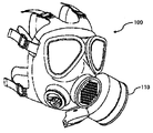
- the gas mask is used to minimize human injury from the attack of enemy chemical weapons in wartime, and the toxic gas introduced from the outside is purified through the purification tank 110 attached to the gas mask 100 as shown in FIG. 1. Only the air is inhaled to allow breathing. Recently, multi-purpose gas masks have been released to minimize the damage to life due to various toxic gases generated in a fire as well as exhibitions.
- the purification tank 100 used for the gas mask 100 includes an absorbent such as activated carbon for chemically adsorbing or decomposing toxic gas and a filter paper for physically filtering particulate matter, thereby purifying the toxic gas chemically / physically. have.
- the capacity to purify the toxic gas in one purifier 110 is limited, so when using the gas mask for a long time exposed to the toxic gas for a long time You must carry a septic container with
- the present invention provides a portable air purifier for decomposing toxic gas contained in the outside air through a metal catalyst layer heated to a predetermined temperature condition, but purifying the toxic gas with a semi-permanent filter unit.
- the purpose is.
- the mask portion A first connection hose having one end connected to the mask part; A second connecting hose accommodating the first connecting hose therein and having an opening for introducing external air into at least a portion of the hose; A case, an external air inlet connected to one end of the second connection hose and introducing external air introduced through the second connection hose into the case, the metal catalyst layer being formed inside the case, and having a predetermined temperature; A filter unit for purifying external air introduced into the case in a heated state, a heater disposed inside the case and heating the filter unit to a predetermined temperature condition for catalytic reaction of the filter unit, and the first connection hose An air purification module connected to the other end of the air purification unit and configured to discharge the purified air through the filter unit to the first connection hose; And it provides a portable air purifier comprising a power supply for supplying power to the heater.
- the filter unit is configured to allow the outside air introduced from the air outside air inlet to be vented, and an inorganic film including a plurality of pores is formed on a surface thereof, and a metal catalyst mother liquid is supported on a part or all of the inorganic film to form a metal.
- a catalyst layer can be formed.
- the purge air discharge part may have a fan therein.
- the second connection hose may be a metal crimped hose.
- the portable air purifier may further include a purifying tank attached to the mask unit and purifying external air to flow into the mask unit.
- the filter unit for removing toxic gases or biochemical contaminants can be used semi-permanently through the catalytic reaction of the metal catalyst layer in the portable air purifier, the inconvenience of having to carry an extra purifier can be eliminated. have.
- FIG. 1 is a view showing a conventional gas mask by way of example
- FIG. 2 is a simplified view of a portable air purifier according to an embodiment of the present invention.
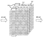
- FIG. 3 is a view showing an exemplary filter unit and a heater unit according to an embodiment of the present invention
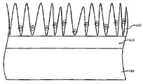
- FIG. 4 is a cross-sectional view of the surface of the filter plate in one embodiment of the present invention.
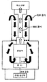
- FIG. 5 is a view showing the air purification process of a portable air purifier according to an embodiment of the present invention.
- FIG. 2 is a block diagram schematically showing a portable air purifier according to an embodiment of the present invention.
- Portable air purifier 200 is a mask unit 210, the first connection hose 220, the second connection hose 230, the air purification module 240 and the power supply 250 Include.
- the mask unit 210 is formed in a shape that seals all or part of the face in order to block the respirator of the portable air purifier user using the portable air purifier 200 from the outside.
- One end of the first connection hose 220 is connected to the mask unit 210, and the other end thereof is connected to the purified air discharge unit 243 of the air purification module 240 which will be described later.
- the first connection hose 220 delivers the purge air discharged through the purge air discharge part 243 into the mask part 210.
- the second connection hose 230 accommodates the first connection hose 220 therein, and an opening 232 for introducing external air into at least a portion of the hose is formed.
- the second connection hose 230 inflows the outside air through the opening 232 as shown in FIG. 3 and delivers it to the outside air inlet 242 of the air purification module 240 which will be described later. .
- the air purification module 240 is connected to one end of the case 241 and the second connection hose 230 and an external air inlet for introducing external air introduced through the second connection hose 230 into the case 241.
- the filter unit 243 It includes a purge air discharge portion 245 for discharging the purified air through the first connection hose 220.
- the filter unit 243 of the air purification module 240 may be configured to allow air to be vented between the filter plates 310 by stacking a plurality of filter plates 310 spaced apart from each other.
- a plurality of vent holes 312 may be formed to increase the area of contact when air passes, thereby making the catalytic reaction more effective.
- the heater 244 may have a rod shape and penetrate the plurality of filter plates 310 to be bonded to the filter plate 310.
- the heater 244 may use a PTC heater, and the number of heaters 244 may also be adjusted according to the width or number of filter plates 310.
- the filter portion 243 may be formed in a cylindrical shape such as a cylinder may be configured to allow gas to pass through the inside of the cylinder. Alternatively, it may be rolled in a spiral form and configured to be breathable. As such, the filter unit 243 may be configured in various ways, and thus, the shape of the filter unit 243 should be understood as representing the technical idea of the present invention if it is configured to be ventilated.
- an inorganic film including a plurality of pores is formed on the surface of the filter portion 243 through an anodization reaction, and a catalyst mother liquid is supported on the inorganic film to form a metal catalyst layer.
- a process of growing an oxide or nitride film formed on the metal surface using an electrolytic reaction can be performed.
- the electrolyte and the current can be brought into contact with the metal substrate existing under the oxide film, and as a result, a film thicker than the oxide film formed by the spontaneous metal oxidation can be formed.
- the film formed through such a process has various properties depending on the process conditions. The thicker the film is formed by using a low concentration of electrolyte and a high current or voltage.
- An oxide film formed by the above method can be used as the inorganic film of the filter portion 243.
- the inorganic coating may be manufactured using a conductive metal such as aluminum.
- a conductive metal such as aluminum.
- alumina which is aluminum oxide, is gradually laminated, and the alumina film thus formed can be used as the inorganic coating of the present invention.
- a metal catalyst layer such as platinum (Pt) or rhodium (Rh) may be inserted between the pores of the inorganic film.
- the metal catalyst layer is completed by supporting the catalyst mother liquid to form a metal catalyst layer and then drying.
- the metal layer 410 serving as the base of the filter unit 243, the transition layer 420 in which the metal constituting the metal layer 410 and the oxide of the metal coexist on the metal layer 410, and the A cross section of the structure in which the inorganic film 430 formed on the transition layer 420 is formed is shown.
- Platinum (Pt) catalyst may be attached to the plurality of pore surfaces as one example of the metal catalyst layer in the plurality of pores included in the inorganic coating 430.
- toxic gas components contained in the outside air cause a catalytic reaction with the metal catalyst layer of the filter unit 210 to the outside.
- Toxic gas components contained in the air are removed. Biochemical contaminants are also chemically burned and removed by catalytic reactions.
- the filter unit 243 purifies the outside air in a heated state through the heater unit 244 at a predetermined temperature condition, the purified air passing through the filter unit 243 is higher than room temperature. It becomes a high temperature state.
- the purified air that has become a high temperature state is continuously maintained at a high temperature state even when discharged to the first connection hose 220 through the purified air discharge part 245.
- the user of the portable air purifier inhales the purified air in such a high temperature state, it may cause difficulty in breathing, thereby forming a separate cooling means outside the first connection hose 220 to cool the surface of the first connection hose 220. It would be desirable to cool the purified air at high temperature to room temperature.
- the portable air purifier 200 may be inferior in portability.
- the outside air is introduced into the outside air of the air purification module 240 through the second connection hose 230 accommodating the first connection hose 220 therein and introducing outside air through the opening 232.
- the external air is brought into contact with the surface of the first connecting hose 220 to cool the surface of the first connecting hose 220.
- FIG. 5 is a view showing the air purification process of a portable air purifier according to an embodiment of the present invention.
- the external air Is introduced through the opening 232 formed in the second connection hose 230, and contacts the outer surface of the first connection hose 220 accommodated inside the second connection hose 230. It is introduced into the case 241 through the outside air inlet 242.
- the purified air of the high temperature state is discharged to the first connection hose 220 through the purge air discharge part 245 and moves to the mask part 210 while contacting the inner surface of the first connection hose 220.
- the outer surface of the first connection hose 220 is in contact with the outside air at room temperature, heat conduction occurs between the inner surface and the outer surface of the first connection hose 220, and thus the heat of the purifying air is first.
- the inner and outer surfaces of the connection hose 220 move to the outside air introduced into the second connection hose 230.
- the purified air in the high temperature state and the outside air in the normal temperature state are kept in thermal equilibrium at a predetermined temperature, so that the temperature of the purified air does not cause discomfort to breathe when the portable air purifier user inhales the purified air. Will be lowered.
- the thermal equilibrium temperature of the purge air and the outside air may be achieved by adjusting the lengths of the first connection hose 220 and the second connection hose 230.
- the first connection hose 220 is a metal corrugated hose having a high conductivity, and when the length of the first connection hose 220 is long to adjust the thermal equilibrium temperature, in order to smoothly discharge the purge air. It may be desirable to further install a fan inside the purge air outlet 245.
- the power supply unit 250 supplies power to the heater 243 that heats the filter unit 244.
- the power supply unit 250 may be any one of an air zinc battery, a lithium ion battery, a manganese battery, an alkaline battery and a fuel cell.
- the portable air purifier 200 when the portable air purifier 200 according to an embodiment of the present invention replaces the power supply unit 250, the operation of the air purifying module 240 is stopped and the air purifying function is lost.
- the power supply unit 250 When the power supply unit 250 is replaced, the toxic gas contained in the outside air may be sucked.
- a purifying tank (not shown) for purifying toxic gas contained in the outside air and flowing into the mask unit 210 is additionally attached to the mask unit 210 to replace the power supply unit 250. It would be desirable to replace 240 to purify the outside air.
- the portable air purifier 200 may semi-permanently use the filter unit 243 for removing toxic gases or biochemical contaminants through the catalytic reaction of the metal catalyst layer.
- Purification of the high temperature state because the temperature of the purified air in the high temperature state can be lowered by maintaining the thermal equilibrium state between the purified air and the outside air through the structure of accommodating the first connection hose 220 inside the second connection hose 230. It is not necessary to provide a separate cooling means for cooling the air.
Landscapes
- Health & Medical Sciences (AREA)
- General Health & Medical Sciences (AREA)
- Business, Economics & Management (AREA)
- Emergency Management (AREA)
- Pulmonology (AREA)
- Life Sciences & Earth Sciences (AREA)
- Zoology (AREA)
- Disinfection, Sterilisation Or Deodorisation Of Air (AREA)
- Respiratory Apparatuses And Protective Means (AREA)
- Exhaust Gas Treatment By Means Of Catalyst (AREA)
Description
Claims (5)
- 마스크부;일단이 상기 마스크부에 연결되는 제 1 연결 호스;내측에 상기 제 1 연결 호스를 수용하고, 호스의 적어도 일부분에 외부 공기를 유입하는 개구가 형성된 제 2 연결 호스;케이스, 상기 제 2 연결 호스의 일단과 연결되고 상기 제 2 연결 호스를 통해 유입된 외부 공기를 상기 케이스 내부로 유입하는 외부 공기 유입부, 상기 케이스 내부에 배치되되 금속 촉매층이 형성되고, 소정의 온도 조건으로 가열된 상태에서 상기 케이스 내부로 유입된 외부 공기를 정화하는 필터부, 상기 케이스 내부에 배치되되 상기 필터부의 촉매 반응을 위해 상기 필터부를 소정의 온도 조건으로 가열하는 히터 및 상기 제 1 연결 호스의 타단과 연결되고, 상기 필터부를 통과하여 정화된 공기를 상기 제 1 연결 호스로 배출하는 정화 공기 배출부를 포함하는 공기 정화 모듈; 및상기 히터에 전력을 공급하는 전원부를 포함하는 것을 특징으로 하는 휴대용 공기 정화기.
- 제 1 항에 있어서,상기 필터부는 상기 공기 외부 공기 유입부로부터 유입된 외부 공기가 통기(通氣) 가능하게 구성되면서 표면에는 다수의 기공을 포함하는 무기 피막이 형성되고 상기 무기 피막의 일부 또는 전부에 금속 촉매 모액을 담지시켜 상기 금속 촉매층을 형성하는 것을 특징으로 하는 휴대용 공기 정화기.
- 제 1 항에 있어서,상기 정화 공기 배출부는 내부에 팬(Fan)을 구비하는 것을 특징으로 하는 휴대용 공기 정화기.
- 제 1 항에 있어서,상기 제 2 연결 호스는 금속 주름 호스인 것을 특징으로 하는 휴대용 공기 정화기.
- 제 1 항에 있어서,상기 마스크부에 부착되되, 외부 공기를 정화하여 상기 마스크부 내부로 유입시키는 정화통을 더 포함하는 것을 특징으로 하는 휴대용 공기 정화기.
Priority Applications (4)
| Application Number | Priority Date | Filing Date | Title |
|---|---|---|---|
| EP13806510.7A EP2865425B1 (en) | 2012-06-21 | 2013-06-19 | Portable air purifier |
| CN201380032362.2A CN104394940A (zh) | 2012-06-21 | 2013-06-19 | 便携式空气净化器 |
| US14/410,088 US9968809B2 (en) | 2012-06-21 | 2013-06-19 | Portable air purifier |
| JP2015518333A JP5998279B2 (ja) | 2012-06-21 | 2013-06-19 | 携帯用空気浄化器 |
Applications Claiming Priority (2)
| Application Number | Priority Date | Filing Date | Title |
|---|---|---|---|
| KR20120066578A KR101332199B1 (ko) | 2012-06-21 | 2012-06-21 | 휴대용 공기 정화기 |
| KR10-2012-0066578 | 2012-06-21 |
Publications (1)
| Publication Number | Publication Date |
|---|---|
| WO2013191468A1 true WO2013191468A1 (ko) | 2013-12-27 |
Family
ID=49769004
Family Applications (1)
| Application Number | Title | Priority Date | Filing Date |
|---|---|---|---|
| PCT/KR2013/005411 Ceased WO2013191468A1 (ko) | 2012-06-21 | 2013-06-19 | 휴대용 공기 정화기 |
Country Status (6)
| Country | Link |
|---|---|
| US (1) | US9968809B2 (ko) |
| EP (1) | EP2865425B1 (ko) |
| JP (1) | JP5998279B2 (ko) |
| KR (1) | KR101332199B1 (ko) |
| CN (1) | CN104394940A (ko) |
| WO (1) | WO2013191468A1 (ko) |
Cited By (2)
| Publication number | Priority date | Publication date | Assignee | Title |
|---|---|---|---|---|
| US9968809B2 (en) | 2012-06-21 | 2018-05-15 | Rekrix Co., Ltd. | Portable air purifier |
| WO2019054586A1 (ko) * | 2017-09-15 | 2019-03-21 | 권순범 | 영유아용 정화 마스크 |
Families Citing this family (11)
| Publication number | Priority date | Publication date | Assignee | Title |
|---|---|---|---|---|
| CN104759045B (zh) * | 2015-04-09 | 2018-02-23 | 徐威 | 储水式呼吸保护装置 |
| KR101600360B1 (ko) * | 2016-01-15 | 2016-03-07 | 고윤한 | 공기 얼굴 마사지 장치 |
| KR102527659B1 (ko) | 2017-11-27 | 2023-05-03 | 삼성전자주식회사 | 공기청정기 |
| KR102683508B1 (ko) * | 2019-08-27 | 2024-07-10 | (주)피노스토리 | 습식 가변형 다층 여과 시스템 및 이를 포함하는 필터 유닛 |
| US12017232B2 (en) | 2020-03-13 | 2024-06-25 | Julian HENLEY | Electro-ionic mask devices for improved protection from airborne biopathogens |
| US11992585B2 (en) | 2020-03-13 | 2024-05-28 | Julian HENLEY | Electro-ionic devices for improved protection from airborne biopathogens |
| FR3109505B1 (fr) * | 2020-04-23 | 2022-05-13 | Commissariat Energie Atomique | Dispositif actif de protection contre agents infectieux ou pathogènes |
| DE102020113117A1 (de) | 2020-05-14 | 2021-11-18 | Fricke Und Mallah Microwave Technology Gmbh | Gesichtsmaske mit Atemluftfilter |
| US20210379318A1 (en) * | 2020-06-09 | 2021-12-09 | Advanced Imaging Research, Inc. | Device and method for deactivating airborne pathogens |
| USD1057918S1 (en) | 2021-06-23 | 2025-01-14 | Sharkninja Operating Llc | Air purifier |
| USD1120265S1 (en) | 2023-07-25 | 2026-03-24 | Sharkninja Operating Llc | Air purifier |
Citations (4)
| Publication number | Priority date | Publication date | Assignee | Title |
|---|---|---|---|---|
| KR200154880Y1 (ko) * | 1996-12-31 | 1999-08-16 | 이건 | 어린이용 방독면 |
| US20070044800A1 (en) * | 2003-03-27 | 2007-03-01 | Colin Church | Respirator |
| JP2008295993A (ja) * | 2007-05-31 | 2008-12-11 | Toyo Living Kk | 光触媒付加のサイクロン式マスク |
| JP3152585U (ja) * | 2009-05-25 | 2009-08-06 | チェン,ウェン−ピン | 温熱機能付きマスク |
Family Cites Families (32)
| Publication number | Priority date | Publication date | Assignee | Title |
|---|---|---|---|---|
| GB1053102A (ko) * | ||||
| US3731678A (en) * | 1971-03-05 | 1973-05-08 | Phyllis Pyzel | Smoke inhalation protector |
| DE3001715A1 (de) * | 1980-01-18 | 1981-09-03 | Drägerwerk AG, 2400 Lübeck | Atemfilter |
| JPS5784744A (en) * | 1980-11-17 | 1982-05-27 | Showa Denko Kk | Catalyst for removing carbon monooxide used in gas mask |
| JPS5825175A (ja) * | 1981-08-07 | 1983-02-15 | 揚 文羊 | 防煙防毒マスク |
| US4502876A (en) * | 1984-01-03 | 1985-03-05 | Behnke Jr Albert R | Cartridge for use in rebreathing apparatus |
| DE3405098A1 (de) * | 1984-02-14 | 1985-08-29 | Drägerwerk AG, 2400 Lübeck | Kohlenoxid-atemschutzgeraet |
| JPS612877A (ja) * | 1984-06-16 | 1986-01-08 | 株式会社フジクラ | 防毒マスク |
| DE3507486C2 (de) * | 1985-03-02 | 1987-01-02 | Drägerwerk AG, 2400 Lübeck | Kohlenstoffmonoxid-Atemluftfilter |
| CA1251117A (en) * | 1985-08-12 | 1989-03-14 | Yoshimasa Nakagawa | Gas mask |
| CN86205992U (zh) * | 1986-08-15 | 1987-10-03 | 余志鹏 | 套筒软管预热式口罩 |
| US4793343A (en) * | 1987-08-20 | 1988-12-27 | Cummins Jr James M | Respiratory heated face mask |
| US5036844A (en) * | 1990-06-19 | 1991-08-06 | Mine Safety Appliances Company | Cover assembly and pre-filter for a respirator |
| US6488900B1 (en) | 1998-10-20 | 2002-12-03 | Mesosystems Technology, Inc. | Method and apparatus for air purification |
| US6349721B1 (en) * | 1999-10-04 | 2002-02-26 | Morning Pride Manufacturing, L.L.C. | Protective cover for air filter and for conduit connecting air filter to breathing mask |
| TW510820B (en) * | 1999-11-30 | 2002-11-21 | Japan Pionics | Method of cleaning of harmful gas and cleaning apparatus |
| CN2533899Y (zh) * | 2002-04-24 | 2003-02-05 | 陕西斯达煤矿安全装备有限责任公司 | 矿用低温一氧化碳过滤式自救器 |
| US6799573B1 (en) * | 2002-12-20 | 2004-10-05 | James D. Bonner | Air filtration system |
| US20060048778A1 (en) * | 2004-09-07 | 2006-03-09 | Honeywell International, Inc. | Low pressure-drop respirator filter |
| US20060231100A1 (en) * | 2005-04-15 | 2006-10-19 | Walker Garry J | Supplied air respirator that has an adjustable length hose |
| JP2006320893A (ja) * | 2005-04-18 | 2006-11-30 | Tokyo Univ Of Agriculture & Technology | 窒素酸化物の選択的還元触媒 |
| US8826905B2 (en) * | 2007-06-01 | 2014-09-09 | Ramses Nashed | Respiratory face mask and breathing circuit assembly |
| KR20090011214U (ko) * | 2008-04-29 | 2009-11-03 | 이앤위즈(주) | 유해오염물질을 제거하는 페록시라디칼 반응관을 구비하는방독면용 정화통과 방독면 |
| CN201248380Y (zh) * | 2008-05-09 | 2009-06-03 | 东莞市宇洁新材料有限公司 | 灰霾和臭氧空气防护口罩 |
| JP2011527939A (ja) * | 2008-07-16 | 2011-11-10 | イー.エム.ダブリュ.エナジー カンパニー リミテッド | 無機膜を用いた排ガス浄化用担体の構造および該担体の製造方法 |
| CN201361380Y (zh) * | 2009-03-18 | 2009-12-16 | 刘�英 | 一种防护口罩 |
| CN101520202B (zh) * | 2009-04-09 | 2010-10-13 | 吉林大学 | 适用于上排式油烟机的油烟净化处理器 |
| WO2011006206A1 (en) * | 2009-07-17 | 2011-01-20 | Paftec Holdings Pty Ltd | Respirator |
| KR101154855B1 (ko) * | 2010-03-11 | 2012-06-18 | 주식회사 이엠따블유에너지 | 공기 정화 모듈 |
| CN101979112A (zh) * | 2010-11-22 | 2011-02-23 | 吉林大学 | 隐形广谱呼吸净化器 |
| KR101527102B1 (ko) * | 2010-11-26 | 2015-06-10 | (주)바이오니아 | 유해물질 제거 장치 |
| KR101332199B1 (ko) | 2012-06-21 | 2013-11-25 | 주식회사 이엠따블유에너지 | 휴대용 공기 정화기 |
-
2012
- 2012-06-21 KR KR20120066578A patent/KR101332199B1/ko not_active Expired - Fee Related
-
2013
- 2013-06-19 US US14/410,088 patent/US9968809B2/en active Active
- 2013-06-19 WO PCT/KR2013/005411 patent/WO2013191468A1/ko not_active Ceased
- 2013-06-19 CN CN201380032362.2A patent/CN104394940A/zh active Pending
- 2013-06-19 JP JP2015518333A patent/JP5998279B2/ja not_active Expired - Fee Related
- 2013-06-19 EP EP13806510.7A patent/EP2865425B1/en not_active Not-in-force
Patent Citations (4)
| Publication number | Priority date | Publication date | Assignee | Title |
|---|---|---|---|---|
| KR200154880Y1 (ko) * | 1996-12-31 | 1999-08-16 | 이건 | 어린이용 방독면 |
| US20070044800A1 (en) * | 2003-03-27 | 2007-03-01 | Colin Church | Respirator |
| JP2008295993A (ja) * | 2007-05-31 | 2008-12-11 | Toyo Living Kk | 光触媒付加のサイクロン式マスク |
| JP3152585U (ja) * | 2009-05-25 | 2009-08-06 | チェン,ウェン−ピン | 温熱機能付きマスク |
Cited By (2)
| Publication number | Priority date | Publication date | Assignee | Title |
|---|---|---|---|---|
| US9968809B2 (en) | 2012-06-21 | 2018-05-15 | Rekrix Co., Ltd. | Portable air purifier |
| WO2019054586A1 (ko) * | 2017-09-15 | 2019-03-21 | 권순범 | 영유아용 정화 마스크 |
Also Published As
| Publication number | Publication date |
|---|---|
| JP2015526125A (ja) | 2015-09-10 |
| CN104394940A (zh) | 2015-03-04 |
| US20150321030A1 (en) | 2015-11-12 |
| US9968809B2 (en) | 2018-05-15 |
| EP2865425A4 (en) | 2016-02-24 |
| KR101332199B1 (ko) | 2013-11-25 |
| EP2865425B1 (en) | 2018-12-05 |
| EP2865425A1 (en) | 2015-04-29 |
| JP5998279B2 (ja) | 2016-09-28 |
Similar Documents
| Publication | Publication Date | Title |
|---|---|---|
| KR101332199B1 (ko) | 휴대용 공기 정화기 | |
| EP3978434B1 (en) | Gas production device, gas production system, iron production system, chemical product production system, and gas production method | |
| WO2011112031A2 (ko) | 공기 정화 모듈 | |
| CN108796533B (zh) | 气体产生器 | |
| EP1819422B1 (en) | Treatment method and treatment apparatus for gas containing nitrous oxide | |
| WO2025246215A1 (zh) | 带干燥剂包的安全型有源电解水分子装置 | |
| CN103331082B (zh) | 一种粒子群电极吸附耦合电催化氧化处理含苯废气的装置 | |
| CN113477075A (zh) | 电化学空气净化消毒装置和电化学空气净化消毒方法 | |
| JP3224950U (ja) | 呼吸マスク | |
| JP6957791B2 (ja) | 電解水素吸引器 | |
| CN223496657U (zh) | 安全型有源电解水分子装置及设备 | |
| JPS6054177A (ja) | ポ−タブル型燃料電池 | |
| CN214370783U (zh) | 一种电化学空气净化装置 | |
| CN118497786A (zh) | 有限空间内的有源电解水分子装置及设备 | |
| CN216738402U (zh) | 一种热焖容器的防爆系统 | |
| CN210620953U (zh) | 一种便携式的多功能氢氧发生器 | |
| CN114060959B (zh) | 除菌装置、空调室内机及空调器 | |
| CN213432441U (zh) | 一种制氢呼吸设备 | |
| CN213096224U (zh) | 基于电场离子化的防护口罩 | |
| CN113862407B (zh) | 一种钢渣热焖容器的防爆系统 | |
| CN107050682A (zh) | 一种空气再生罐和呼吸面罩 | |
| CN113457316A (zh) | 一种可消除有毒气体的电池包 | |
| CN223255453U (zh) | 有限空间内的有源电解水分子装置及设备 | |
| CN214914431U (zh) | 一种用于亚硫酸钠制备的尾气脱硫装置 | |
| CN222550563U (zh) | 带干燥剂包的安全型有源电解水分子装置 |
Legal Events
| Date | Code | Title | Description |
|---|---|---|---|
| 121 | Ep: the epo has been informed by wipo that ep was designated in this application |
Ref document number: 13806510 Country of ref document: EP Kind code of ref document: A1 |
|
| WWE | Wipo information: entry into national phase |
Ref document number: 2013806510 Country of ref document: EP |
|
| ENP | Entry into the national phase |
Ref document number: 2015518333 Country of ref document: JP Kind code of ref document: A |
|
| WWE | Wipo information: entry into national phase |
Ref document number: 14410088 Country of ref document: US |
|
| NENP | Non-entry into the national phase |
Ref country code: DE |