WO2014002171A1 - 工作機械 - Google Patents
工作機械 Download PDFInfo
- Publication number
- WO2014002171A1 WO2014002171A1 PCT/JP2012/066181 JP2012066181W WO2014002171A1 WO 2014002171 A1 WO2014002171 A1 WO 2014002171A1 JP 2012066181 W JP2012066181 W JP 2012066181W WO 2014002171 A1 WO2014002171 A1 WO 2014002171A1
- Authority
- WO
- WIPO (PCT)
- Prior art keywords
- bed
- axis
- machine tool
- moving body
- pair
- Prior art date
- Legal status (The legal status is an assumption and is not a legal conclusion. Google has not performed a legal analysis and makes no representation as to the accuracy of the status listed.)
- Ceased
Links
Images

Classifications
-
- B—PERFORMING OPERATIONS; TRANSPORTING
- B23—MACHINE TOOLS; METAL-WORKING NOT OTHERWISE PROVIDED FOR
- B23Q—DETAILS, COMPONENTS, OR ACCESSORIES FOR MACHINE TOOLS, e.g. ARRANGEMENTS FOR COPYING OR CONTROLLING; MACHINE TOOLS IN GENERAL CHARACTERISED BY THE CONSTRUCTION OF PARTICULAR DETAILS OR COMPONENTS; COMBINATIONS OR ASSOCIATIONS OF METAL-WORKING MACHINES, NOT DIRECTED TO A PARTICULAR RESULT
- B23Q1/00—Members which are comprised in the general build-up of a form of machine, particularly relatively large fixed members
- B23Q1/01—Frames, beds, pillars or like members; Arrangement of ways
- B23Q1/015—Frames, beds, pillars
-
- B—PERFORMING OPERATIONS; TRANSPORTING
- B23—MACHINE TOOLS; METAL-WORKING NOT OTHERWISE PROVIDED FOR
- B23Q—DETAILS, COMPONENTS, OR ACCESSORIES FOR MACHINE TOOLS, e.g. ARRANGEMENTS FOR COPYING OR CONTROLLING; MACHINE TOOLS IN GENERAL CHARACTERISED BY THE CONSTRUCTION OF PARTICULAR DETAILS OR COMPONENTS; COMBINATIONS OR ASSOCIATIONS OF METAL-WORKING MACHINES, NOT DIRECTED TO A PARTICULAR RESULT
- B23Q1/00—Members which are comprised in the general build-up of a form of machine, particularly relatively large fixed members
- B23Q1/01—Frames, beds, pillars or like members; Arrangement of ways
- B23Q1/017—Arrangements of ways
-
- B—PERFORMING OPERATIONS; TRANSPORTING
- B23—MACHINE TOOLS; METAL-WORKING NOT OTHERWISE PROVIDED FOR
- B23Q—DETAILS, COMPONENTS, OR ACCESSORIES FOR MACHINE TOOLS, e.g. ARRANGEMENTS FOR COPYING OR CONTROLLING; MACHINE TOOLS IN GENERAL CHARACTERISED BY THE CONSTRUCTION OF PARTICULAR DETAILS OR COMPONENTS; COMBINATIONS OR ASSOCIATIONS OF METAL-WORKING MACHINES, NOT DIRECTED TO A PARTICULAR RESULT
- B23Q11/00—Accessories fitted to machine tools for keeping tools or parts of the machine in good working condition or for cooling work; Safety devices specially combined with or arranged in, or specially adapted for use in connection with, machine tools
- B23Q11/0042—Devices for removing chips
- B23Q11/0053—Devices for removing chips using the gravity force
-
- B—PERFORMING OPERATIONS; TRANSPORTING
- B23—MACHINE TOOLS; METAL-WORKING NOT OTHERWISE PROVIDED FOR
- B23C—MILLING
- B23C1/00—Milling machines not designed for particular work or special operations
- B23C1/02—Milling machines not designed for particular work or special operations with one horizontal working-spindle
- B23C1/027—Milling machines not designed for particular work or special operations with one horizontal working-spindle with working-spindle movable in a vertical direction
-
- B—PERFORMING OPERATIONS; TRANSPORTING
- B23—MACHINE TOOLS; METAL-WORKING NOT OTHERWISE PROVIDED FOR
- B23C—MILLING
- B23C2230/00—Details of chip evacuation
-
- B—PERFORMING OPERATIONS; TRANSPORTING
- B23—MACHINE TOOLS; METAL-WORKING NOT OTHERWISE PROVIDED FOR
- B23Q—DETAILS, COMPONENTS, OR ACCESSORIES FOR MACHINE TOOLS, e.g. ARRANGEMENTS FOR COPYING OR CONTROLLING; MACHINE TOOLS IN GENERAL CHARACTERISED BY THE CONSTRUCTION OF PARTICULAR DETAILS OR COMPONENTS; COMBINATIONS OR ASSOCIATIONS OF METAL-WORKING MACHINES, NOT DIRECTED TO A PARTICULAR RESULT
- B23Q1/00—Members which are comprised in the general build-up of a form of machine, particularly relatively large fixed members
- B23Q1/70—Stationary or movable members for carrying working-spindles for attachment of tools or work
-
- B—PERFORMING OPERATIONS; TRANSPORTING
- B23—MACHINE TOOLS; METAL-WORKING NOT OTHERWISE PROVIDED FOR
- B23Q—DETAILS, COMPONENTS, OR ACCESSORIES FOR MACHINE TOOLS, e.g. ARRANGEMENTS FOR COPYING OR CONTROLLING; MACHINE TOOLS IN GENERAL CHARACTERISED BY THE CONSTRUCTION OF PARTICULAR DETAILS OR COMPONENTS; COMBINATIONS OR ASSOCIATIONS OF METAL-WORKING MACHINES, NOT DIRECTED TO A PARTICULAR RESULT
- B23Q11/00—Accessories fitted to machine tools for keeping tools or parts of the machine in good working condition or for cooling work; Safety devices specially combined with or arranged in, or specially adapted for use in connection with, machine tools
- B23Q11/0042—Devices for removing chips
-
- B—PERFORMING OPERATIONS; TRANSPORTING
- B23—MACHINE TOOLS; METAL-WORKING NOT OTHERWISE PROVIDED FOR
- B23Q—DETAILS, COMPONENTS, OR ACCESSORIES FOR MACHINE TOOLS, e.g. ARRANGEMENTS FOR COPYING OR CONTROLLING; MACHINE TOOLS IN GENERAL CHARACTERISED BY THE CONSTRUCTION OF PARTICULAR DETAILS OR COMPONENTS; COMBINATIONS OR ASSOCIATIONS OF METAL-WORKING MACHINES, NOT DIRECTED TO A PARTICULAR RESULT
- B23Q11/00—Accessories fitted to machine tools for keeping tools or parts of the machine in good working condition or for cooling work; Safety devices specially combined with or arranged in, or specially adapted for use in connection with, machine tools
- B23Q11/0042—Devices for removing chips
- B23Q11/0067—Devices for removing chips chip containers located under a machine or under a chip conveyor
-
- Y—GENERAL TAGGING OF NEW TECHNOLOGICAL DEVELOPMENTS; GENERAL TAGGING OF CROSS-SECTIONAL TECHNOLOGIES SPANNING OVER SEVERAL SECTIONS OF THE IPC; TECHNICAL SUBJECTS COVERED BY FORMER USPC CROSS-REFERENCE ART COLLECTIONS [XRACs] AND DIGESTS
- Y02—TECHNOLOGIES OR APPLICATIONS FOR MITIGATION OR ADAPTATION AGAINST CLIMATE CHANGE
- Y02P—CLIMATE CHANGE MITIGATION TECHNOLOGIES IN THE PRODUCTION OR PROCESSING OF GOODS
- Y02P70/00—Climate change mitigation technologies in the production process for final industrial or consumer products
- Y02P70/10—Greenhouse gas [GHG] capture, material saving, heat recovery or other energy efficient measures, e.g. motor control, characterised by manufacturing processes, e.g. for rolling metal or metal working
-
- Y—GENERAL TAGGING OF NEW TECHNOLOGICAL DEVELOPMENTS; GENERAL TAGGING OF CROSS-SECTIONAL TECHNOLOGIES SPANNING OVER SEVERAL SECTIONS OF THE IPC; TECHNICAL SUBJECTS COVERED BY FORMER USPC CROSS-REFERENCE ART COLLECTIONS [XRACs] AND DIGESTS
- Y10—TECHNICAL SUBJECTS COVERED BY FORMER USPC
- Y10T—TECHNICAL SUBJECTS COVERED BY FORMER US CLASSIFICATION
- Y10T409/00—Gear cutting, milling, or planing
- Y10T409/30—Milling
- Y10T409/30392—Milling with means to protect operative or machine [e.g., guard, safety device, etc.]
-
- Y—GENERAL TAGGING OF NEW TECHNOLOGICAL DEVELOPMENTS; GENERAL TAGGING OF CROSS-SECTIONAL TECHNOLOGIES SPANNING OVER SEVERAL SECTIONS OF THE IPC; TECHNICAL SUBJECTS COVERED BY FORMER USPC CROSS-REFERENCE ART COLLECTIONS [XRACs] AND DIGESTS
- Y10—TECHNICAL SUBJECTS COVERED BY FORMER USPC
- Y10T—TECHNICAL SUBJECTS COVERED BY FORMER US CLASSIFICATION
- Y10T409/00—Gear cutting, milling, or planing
- Y10T409/30—Milling
- Y10T409/304088—Milling with means to remove chip
Definitions
- the present invention relates to a machine tool for machining a workpiece by relatively moving between a tool mounted on a spindle and a workpiece attached to a table.
- X-, Y-, and Z-axis moving bodies, guides, feed driving devices, chip discharging devices, and the like are appropriately arranged.
- each moving body that moves in the X-, Y-, and Z-axis directions is provided on the rear surface of the base.
- the feed mechanism which moves an up-and-down moving body to an up-down direction along a guide rail is arrange
- This feed mechanism includes a pair of ball screws as vertical feed screws arranged in parallel to each other, and a pair of feed motors that individually rotate and drive these ball screws.
- the feed screw is disposed above the base. Since a moving space for the vertical moving body must be secured above the base, the feed motor must be attached to the upper end of the ball screw. Therefore, the feed motor having a relatively heavy weight is arranged at a position higher than the tool, and the center of gravity of the machine tool is set at a high position together with the guide rail of the vertical moving body arranged above the discharge hole. Will be set. As a result, the stability of the machine tool is impaired, and there is a problem that the overall height of the machine is increased and the machine size is increased.
- the present invention has a technical problem to solve such problems of the prior art, and it is a compact that can reliably discharge chips while realizing high stability by setting the center of gravity at a lower position than before.
- the purpose is to provide a machine tool.
- a chip duct for discharging chips inside the bed to the outside of the machine is provided from the chip discharge opening opened in the left and right central part of the rear surface of the bed toward the rear, and a bifurcated shape straddling the chip duct Since the vertical moving body is moved up and down along a pair of vertical guides extending vertically on the rear surface or side surface of the bed on both the left and right sides of the chip duct, the chip duct is moved to the rear surface of the bed. The cross-sectional area of the chip discharge port and the chip duct is increased, and the discharge of the chip and the machining liquid becomes efficient and reliable.
- the vertical guide is extended to low positions on both the left and right sides of the chip duct, and the guided part of the bifurcated leg of the vertical moving body is overlapped to lower the center of gravity of the machine and move up and down
- the body can be guided and supported over a long vertical range, and the stability of the machine can be improved without increasing the size of the machine.
- FIG. 1 is a side view schematically showing a structure of a machine tool according to an embodiment of the present invention.
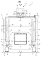
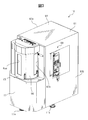
- FIG. 2 is a rear view of the machine tool as viewed in the direction of the arrow 2-2 in FIG. 1. It is a perspective view which shows roughly the external appearance of the machine tool shown with the splash guard which surrounds the machine tool of FIG.
- FIG. 1 is a side view schematically showing the structure of a machine tool according to an embodiment of the present invention
- FIG. 2 is a rear view of the machine tool viewed in the direction of arrow 2-2 in FIG.
- FIG. 3 is a perspective view schematically showing the appearance of the machine tool shown together with the splash guard.
- the direction of the tip of a tool attached to the tip of a spindle which will be described later, is the front side of the machine tool.
- the machine tool 10 is a four-axis horizontal machining center having, for example, a linear movement axis in three orthogonal directions of XYZ and a B axis that is one rotary feed axis.
- the left-right direction (perpendicular to the paper surface of FIG. 1) of the machine tool 10 is defined as the X axis
- the up-down direction is defined as the Y-axis
- the front-rear direction left-right direction in FIG. 1
- the B axis is a rotary feed axis centered on a vertical axis parallel to the Y axis.
- the 4-axis horizontal machining center for example, a 5-axis machine, a vertical machining center, a milling machine, an electric discharge machine, or the like may be used for the machine tool 10.
- the machine tool 10 includes a bed 12 as a base supported on the floor of a factory or the like.
- the bed 12 includes a hollow prism-shaped bed main body 13 and a pair of left and right side walls 14 protruding rearward from the rear surface of the bed main body 13 in the Z-axis direction.
- the bed 12 is supported by a plurality of leveling blocks that can be adjusted in height as support members, in this embodiment. More specifically, the bed 12 is supported by one front leveling block 11 a disposed at the front center portion of the bed main body 13 and a rear leveling block 11 b disposed at the rear end of each of the pair of side walls 14. ing.
- a table 15 is disposed on the upper surface of the bed body 13.
- the table 15 is rotationally fed in the B-axis direction about a rotation axis extending parallel to the Y-axis by a B-axis servomotor 15a incorporated in the bed main body 13.
- a double-sided scale 16 is fixed on the table 15.
- the double-sided scale 16 has mounting surfaces 16a and 16b arranged back to back for mounting the workpiece W.
- the machine tool 10 includes a vertical moving body 21 that reciprocates linearly in the vertical direction along the Y axis on the rear surface of the bed main body 13.
- a left and right moving body 23 that is linearly reciprocated in the left and right direction along the X axis is attached to the upper surface of the up and down moving body 21.
- a front-rear moving body 24 that reciprocates linearly in the front-rear direction along the Z axis is attached to the left-right moving body 23.
- a spindle head 25 is attached to the front-rear moving body 24 to support the spindle 26 rotatably about a rotation axis O parallel to the Z axis.
- a tool 27 is detachably mounted on the tip of the main shaft 26 so as to face the workpiece W fixed to one mounting surface of the double-faced scale 16.
- a Y-axis guide rail 28 as a pair of left and right upper and lower guides extending in the Y-axis direction (vertical direction) is attached to the rear surface of the bed body 13, and extends outside the Y-axis guide rail 28 in the Y-axis direction.
- a Y-axis ball screw 35 as a pair of provided vertical feed screws is attached.
- a bracket 31 is provided on the rear surface of the bed body 13. In the present embodiment, the bracket 31 is formed integrally with the side wall 14 so as to protrude from the inner side surface of the side wall 14.
- a Y-axis servo motor 30 as a vertical feed motor is attached to the bracket 31.
- the bracket 31 is formed with a through hole 32 penetrating from the upper surface to the lower surface of the bracket 31 in the Y-axis direction.
- the Y-axis servomotor 30 has an output shaft 30a protruding upward through the through hole 32. It is attached to the lower surface of the bracket 31.
- the output shaft 30 a is connected to the lower end of the Y-axis ball screw 35 via the coupling 34.
- the Y-axis ball screw 35 is arranged as close as possible to the rear leveling block 11b.
- the vertical moving body 21 includes a pair of left and right legs 22 that are spaced apart from each other in the Y-axis direction and extend downward in a bifurcated manner.
- a Y-axis guide block 29 is attached to the vertically moving body 21, and the vertically moving body 21 is supported by the Y-axis guide rail 28 so as to be slidable along the Y-axis guide rail 28 via the Y-axis guide block 29. Is done.
- the Y-axis guide block 29 is arranged so that the Y-axis guide rail 28 overlaps the pair of leg portions 22 when the vertically moving body 21 is attached to the rear surface of the bed body 13. Yes.
- the vertical moving body 21 is provided with a pair of upper and lower Y-axis guide blocks 29 for each of the pair of Y-axis guide rails 28.
- One guide block is disposed on each of the pair of leg portions 22.
- a nut 36 that engages with the Y-axis ball screw 35 is further attached to the vertical moving body 21.
- the vertical moving body 21 is driven in the vertical direction according to the rotation direction and the rotation amount of the Y-axis servomotor 30.
- the Y-axis servomotor 30 and the Y-axis ball screw 35 constitute the vertical drive means of the present invention.
- the Y-axis ball screw 35 may be at least one of left and right.
- the horizontal dimension of the up-and-down moving body 21 needs only to be a minimum width in which the guide block 29 can be accommodated, and it is preferable to reduce the weight by projecting the nut 36 portion to the left and right.
- An X-axis guide rail 37 as a pair of left and right guides extending in the X-axis direction and an X-axis as a left-right feed screw extending in the X-axis direction between the pair of X-axis guide rails 37 are disposed on the upper surface of the vertical moving body 21.
- a ball screw 41 is attached.
- An X-axis guide block 38 is attached to the left-right moving body 23, and the left-right moving body 23 is slidable in the left-right direction along the X-axis guide rail 37 via the X-axis guide block 38. 37.
- an X-axis servo motor 39 as a left-right feed motor is attached to the vertical moving body 21.
- An output shaft (not shown) of the X-axis servomotor 39 is connected to the X-axis ball screw 41 via a coupling (not shown).
- a nut 42 that engages with the X-axis ball screw 41 is further attached to the left-right moving body 23.
- the left-right moving body 23 moves left and right according to the rotation direction and the rotation amount of the X-axis servo motor 39.
- the body 23 is driven in the left-right direction.
- the X-axis servo motor 39 and the X-axis ball screw 41 constitute the left / right driving means of the present invention.
- a Z-axis guide rail 43 as a pair of left and right front and rear guides extending in the Z-axis direction, and a Z as a front and rear feed screw extending in the Z-axis direction between the pair of Z-axis guide rails 43.
- a shaft ball screw 46 is attached.
- a Z-axis guide block 44 is attached to the front-rear moving body 24, and the front-rear moving body 24 is slidable in the front-rear direction along the Z-axis guide rail 43 via the Z-axis guide block 44. 43 is supported.
- a Z-axis servo motor 45 as a forward / backward feed motor is attached to the left / right moving body 23.
- An output shaft (not shown) of the Z-axis servomotor 45 is connected to a Z-axis ball screw 46 through a coupling (not shown).
- a nut 47 that engages with the Z-axis ball screw 46 is further attached to the front-rear moving body 24.
- the Z-axis servo motor 45 rotates, the front-rear moving body 24 moves back and forth according to the rotation direction and rotation amount of the Z-axis servo motor 45.
- the body 24 is driven in the front-rear direction.
- the Z-axis servomotor 45 and the Z-axis ball screw 46 constitute the front-rear drive means of the present invention.
- a built-in type spindle motor (not shown) is incorporated in the spindle head 25.
- the spindle 26 and the tool 27 are driven to rotate about the rotation axis O by the spindle motor.
- the tool 27 moves relative to the workpiece W by linear movement in the XYZ directions of the left / right moving body 23, the up / down moving body 21, and the front / rear moving body 24. This relative movement is controlled by an NC device (not shown) incorporated in the machine tool 10.
- the tool 27 that rotates during the relative movement between the tool 27 and the workpiece W contacts the workpiece W at a predetermined processing point. In this way, the workpiece W is processed into a desired shape.
- a cavity 51 opened upward is formed in the bed main body 13.
- a shooter 52 disposed below the table 15 is formed on the inner wall of the cavity 51, and an opening 13 a as a chip discharge port is formed on the rear surface of the bed main body 13.
- the shooter 52 includes an inclined surface that is lowered from the front to the rear of the bed main body 13 toward the opening 13a and an inclined surface that is directed downward on the left and right inner walls. Chips generated during machining of the workpiece W and machining fluid injected into the machining area of the workpiece W fall from the periphery of the table 15 into the cavity 51 and further move toward the opening 13 a along the shooter 52. .
- a chip duct 53 for discharging chips and machining fluid to the outside of the machine, that is, to the outside of the cavity 51 of the bed body 13 is attached to the rear surface of the bed body 13.
- the chip duct 53 extends rearward from the rear surface of the bed main body 13 between the leg portions 22 of the vertical moving body 21.
- the chip duct 53 is attached at one end so as to surround the opening 13a on the rear surface of the bed body 13 by, for example, a plurality of bolts.
- the other end 53 b of the chip duct 53 is connected to a chip receiver 56.
- the chip receiver 56 is a thin tray-like member opened upward, and the bottom wall is a mesh (not shown).
- a machining liquid tank 54 is disposed below the chip receiver 56.
- the chip duct 53 is inclined downward so as to approach the floor surface from the shooter 52 toward the machining liquid tank 54. In this way, the chips and machining fluid discharged from the opening 13 a to the outside of the machine are guided to the chip receiver 56 by the chip duct 53. In the chip receiver 56, the machining liquid is filtered through the mesh on the bottom wall of the chip receiver 56 and then falls to the machining liquid tank 54, and only the chips accumulate on the bottom wall of the chip receiver 56. Chips deposited on the chip receiver 56 are periodically collected by the operator.
- the machining fluid tank 54 stores the machining fluid guided from the shooter 52 by the chip duct 53.
- a pump 55 is attached to the machining liquid tank 54.
- the pump 55 supplies the machining liquid stored in the machining liquid tank 54 toward the machining area of the workpiece W.
- a filter (not shown) may be further provided in the machining liquid tank 54, and fine chips may be further filtered prior to supply to the machining area. Thus, the machining fluid is reused.
- the machine tool 10 includes, for example, a box-shaped splash guard 61 that forms an internal space that accommodates all the above-described components.
- the splash guard 61 includes a front panel 62, left and right side panels 63a and 63b, and a top panel 64 that cover the lower front portion, both sides, the top, and the rear surface of the machine tool 10.
- the upper portion of the front surface of the machine tool 10, particularly the space where the double-sided scale 16 is disposed, is covered with slide doors 65 and 66.
- the sliding doors 65 and 66 are formed with rectangular monitoring windows 65a and 66a, and a transparent glass plate is fitted into the monitoring windows 65a and 66a.
- An operation panel 68 is incorporated in the right side panel 63b, and the operation panel 68 is connected to the NC device described above.
- the operation panel 68 is provided with a display panel for displaying the operation state of the above-described components and various input buttons.
- An operator of the machine tool 10 can input a machining program and various machining parameters to the NC device via the operation panel 68.
- the machining program may be input via a communication network such as a factory LAN.
- the pair of left and right Y-axis guide rails 28 extending in the vertical direction are disposed in the vicinity of both sides of the bed body 13 on the rear surface of the bed body 13.
- a vertically movable body 21 having a pair of leg portions 22 extending downward in a bifurcated shape is attached to the bed body 13 so as to be movable in the vertical direction along a pair of left and right Y-axis guide rails 28.
- a pair of left and right Y-axis ball screws 35 are provided in the vicinity of the pair of left and right Y-axis guide rails 28 in parallel in the vertical direction.
- a mating nut 36 is provided on the vertical moving body 21.
- the pair of left and right Y-axis guide rails 28 are arranged so as to overlap with the pair of left and right legs 22 extending downward in a bifurcated shape of the vertical moving body 21 when the vertical moving body 21 is attached to the rear surface of the bed body 13.
- a chip duct 53 for discharging chips and machining fluid to the outside of the machine is provided.
- the pair of left and right Y-axis ball screws 35 are provided in the vicinity of both sides of the bed body 13 on the rear surface of the bed body 13 and in parallel with the pair of left and right Y-axis guide rails 28.
- the Y-axis servomotor 30 is connected to the lower end of each Y-axis ball screw 35.
- the Y-axis servomotor 30 is attached to a bracket 31, and the bracket 31 is formed integrally with the side wall 14 so as to protrude from the inner side surface of the side wall 14.
- a rear leveling block 11 b that supports a rear portion of the machine tool 10 is disposed in the vicinity of the bracket 31 on the side wall 14, that is, in the vicinity of the Y-axis servomotor 30.
- the Y-axis ball screw 35 that drives the vertical moving body 21 that is the heaviest moving body in the machine tool 10 in the vertical direction the rigidity of the entire machine tool 10 is set.
- the vertical moving body 21 can be moved up and down at high speed and with high accuracy.
- the Y-axis servo motor 30 and the Y-axis ball screw 35 are disposed on the rear surface of the bed body 13, and the Y-axis servo motor 30 is connected to the lower end of the Y-axis ball screw 35.
- the Y-axis guide rail 28, the Y-axis servo motor 30, and the Y-axis ball screw 35 are disposed below the spindle head 25.
- the Y-axis guide rail 28 is disposed so that the lower end extends to the vicinity of the floor surface, and the Y-axis servo motor 30 is disposed adjacent to the floor surface.
- the vertical moving body 21 is formed in a bifurcated shape so as to dodge the chip duct 53, the guide block 29 is provided on the leg portion 22, and the vertical moving body 21 is supported in the vertical direction with a long span in the vertical direction.
- the machine tool 10 having higher stability than ever can be realized.
- the processing accuracy in the machine tool 10 can be improved.
- the Y-axis servomotor 30 does not have to be disposed at the upper end of the machine tool 10, the overall height of the machine tool 10 can be reduced.
- the pair of Y-axis guide rails 28 are not vertically extended from the rear surface of the bed main body 13 but are extended in the vertical direction behind the side surface of the bed main body 13 and the vertical moving body 21 is moved in the vertical direction on the side surface side of the bed main body 13. You may comprise.
Landscapes
- Engineering & Computer Science (AREA)
- Mechanical Engineering (AREA)
- Machine Tool Units (AREA)
- Turning (AREA)
- Auxiliary Devices For Machine Tools (AREA)
Description
主軸に装着した工具とテーブルに取付けたワークとの間で相対移動させ、前記ワークを加工する工作機械において、
基台となり、上面に前記テーブルが設けられたベッドと、
前記ベッドの後面左右中央部に開口した切りくず排出口から後方へ向けて設けられ、前記ベッド内部の切りくずを機外へ排出する切りくずダクトと、
前記切りくずダクトの左右両側の前記ベッドの後面又は側面に上下方向に延設された一対の上下ガイドに沿って前記ベッドの後面側で上下移動し、前記切りくずダクトを跨ぐ二叉形状の上下移動体と、
前記上下移動体を前記上下ガイドに沿って移動させる上下駆動手段と、
を具備する工作機械が提供される。
11a 前レベリングブロック
11b 後レベリングブロック
12 ベッド
13a 開口部
14 側壁
15 テーブル
21 上下移動体
22 脚部
23 左右移動体
24 前後移動体
25 主軸頭
26 主軸
27 工具
28 Y軸ガイドレール
29 Y軸ガイドブロック
30 Y軸サーボモータ
35 Y軸ボールねじ
36 ナット
37 X軸ガイドレール
43 Z軸ガイドレール
52 シュータ
53 切りくずダクト
54 加工液タンク
56 切りくず受け
Claims (4)
- 主軸に装着した工具とテーブルに取付けたワークとの間で相対移動させ、前記ワークを加工する工作機械において、
基台となり、上面に前記テーブルが設けられたベッドと、
前記ベッドの後面左右中央部に開口した切りくず排出口から後方へ向けて設けられ、前記ベッド内部の切りくずを機外へ排出する切りくずダクトと、
前記切りくずダクトの左右両側の前記ベッドの後面又は側面に上下方向に延設された一対の上下ガイドに沿って前記ベッドの後面側で上下移動し、前記切りくずダクトを跨ぐ二叉形状の上下移動体と、
前記上下移動体を前記上下ガイドに沿って移動させる上下駆動手段と、
を具備することを特徴とした工作機械。 - 前記上下移動体は、二叉状に下方に延びる一対の脚部を有しており、
前記左右一対の上下ガイドは、前記上下移動体を前記ベッドの後面側に取付けたときに、該上下移動体の二叉状に下方に延びる一対の前記脚部と重なるように配置されている請求項1に記載の工作機械。 - 前記上下駆動手段は、前記左右一対の上下ガイドと平行に延設された左右一対の送りねじを有する請求項1又は2に記載の工作機械。
- 前記ベッドは、前記テーブルの下方に切りくず及び加工液を受けるシュータが形成され、かつ、該ベッドの後面に切りくず排出口が形成されており、切りくず及び加工液が前記シュータから前記切りくず排出口を通過して前記切りくずダクトに排出されるようにした請求項1に記載の工作機械。
Priority Applications (5)
| Application Number | Priority Date | Filing Date | Title |
|---|---|---|---|
| EP12879925.1A EP2865485B1 (en) | 2012-06-25 | 2012-06-25 | Machine tool |
| JP2014522247A JP5766353B2 (ja) | 2012-06-25 | 2012-06-25 | 工作機械 |
| PCT/JP2012/066181 WO2014002171A1 (ja) | 2012-06-25 | 2012-06-25 | 工作機械 |
| US14/409,776 US9469001B2 (en) | 2012-06-25 | 2012-06-25 | Machine tool |
| CN201280074249.6A CN104411453B (zh) | 2012-06-25 | 2012-06-25 | 机床 |
Applications Claiming Priority (1)
| Application Number | Priority Date | Filing Date | Title |
|---|---|---|---|
| PCT/JP2012/066181 WO2014002171A1 (ja) | 2012-06-25 | 2012-06-25 | 工作機械 |
Publications (1)
| Publication Number | Publication Date |
|---|---|
| WO2014002171A1 true WO2014002171A1 (ja) | 2014-01-03 |
Family
ID=49782406
Family Applications (1)
| Application Number | Title | Priority Date | Filing Date |
|---|---|---|---|
| PCT/JP2012/066181 Ceased WO2014002171A1 (ja) | 2012-06-25 | 2012-06-25 | 工作機械 |
Country Status (5)
| Country | Link |
|---|---|
| US (1) | US9469001B2 (ja) |
| EP (1) | EP2865485B1 (ja) |
| JP (1) | JP5766353B2 (ja) |
| CN (1) | CN104411453B (ja) |
| WO (1) | WO2014002171A1 (ja) |
Cited By (1)
| Publication number | Priority date | Publication date | Assignee | Title |
|---|---|---|---|---|
| US11272810B2 (en) * | 2014-03-14 | 2022-03-15 | Spectrum Brands, Inc. | Food preparation appliance for use with a remote communication device |
Families Citing this family (6)
| Publication number | Priority date | Publication date | Assignee | Title |
|---|---|---|---|---|
| EP2756904B1 (en) * | 2013-01-17 | 2017-03-29 | Agie Charmilles SA | Electrical discharge milling machine |
| CN107008982A (zh) * | 2017-04-25 | 2017-08-04 | 谭清平 | 立式线切割机床 |
| DE102017007962A1 (de) * | 2017-08-24 | 2019-02-28 | Deckel Maho Seebach Gmbh | Werkzeugmaschine |
| DE102018201419A1 (de) | 2018-01-30 | 2019-08-01 | Deckel Maho Pfronten Gmbh | Werkzeugmaschine |
| CN111266640A (zh) * | 2020-04-02 | 2020-06-12 | 佛山市顺德区新马木工机械设备有限公司 | 一种便于排屑的加工机台 |
| CN112091242A (zh) * | 2020-09-15 | 2020-12-18 | 哈尔滨工业大学(深圳) | 一种用于机床主轴自动归位装置 |
Citations (4)
| Publication number | Priority date | Publication date | Assignee | Title |
|---|---|---|---|---|
| US4955770A (en) * | 1988-08-31 | 1990-09-11 | Kitamura Machinery Co., Ltd. | Bed for a machine tool |
| JPH06226583A (ja) * | 1992-12-07 | 1994-08-16 | Makino Milling Mach Co Ltd | 切屑処理装置を備えた工作機械 |
| JP2002326137A (ja) * | 2001-05-02 | 2002-11-12 | Makino Milling Mach Co Ltd | 工作機械 |
| JP2007075926A (ja) | 2005-09-13 | 2007-03-29 | Mori Seiki Co Ltd | 工作機械 |
Family Cites Families (15)
| Publication number | Priority date | Publication date | Assignee | Title |
|---|---|---|---|---|
| AT269599B (de) * | 1967-03-24 | 1969-03-25 | Deckel Fa Friedrich | Fräs- und Bohrwerk |
| DE4441253A1 (de) * | 1994-11-19 | 1996-05-23 | Hermle Berthold Maschf Ag | Werkzeugmaschine, insbesondere Bohr- und Fräsmaschine |
| DE10006897A1 (de) * | 2000-02-16 | 2001-09-06 | Deckel Maho Gmbh | Universal-Werkzeugmaschine |
| IT249759Y1 (it) * | 2000-03-28 | 2003-05-28 | Machining Ct S Mfg S P A | Centro di lavoro di tipo perfezionato |
| JP3353084B2 (ja) * | 2000-05-10 | 2002-12-03 | ホーコス株式会社 | コラム移動形マシンニングセンタ |
| JP3357947B2 (ja) * | 2000-10-12 | 2002-12-16 | ホーコス株式会社 | 工作機械 |
| JP3720298B2 (ja) * | 2001-12-28 | 2005-11-24 | 株式会社森精機製作所 | 工作機械の回転割り出し装置 |
| JP4480040B2 (ja) * | 2004-04-07 | 2010-06-16 | エイチピーティー シナジー エス.アール.エル. | 可動式支柱を備える水平型ボールフライス盤 |
| JP3697697B1 (ja) * | 2004-11-26 | 2005-09-21 | 厚夫 渡部 | 横形マシニングセンタ、および、それによる加工方法 |
| JP2007061998A (ja) * | 2005-09-02 | 2007-03-15 | Brother Ind Ltd | 工作機械 |
| JP4210307B2 (ja) * | 2007-01-29 | 2009-01-14 | ファナック株式会社 | 切粉排出構造を有する工作機械 |
| CN101970172B (zh) * | 2008-03-14 | 2013-09-04 | 株式会社牧野铣床制作所 | 机床 |
| JP5328782B2 (ja) * | 2008-05-27 | 2013-10-30 | 株式会社牧野フライス製作所 | 工作機械 |
| WO2010113617A1 (ja) * | 2009-03-31 | 2010-10-07 | コマツNtc株式会社 | 横形工作機械 |
| CN201604004U (zh) * | 2009-10-29 | 2010-10-13 | 大连科德数控有限公司 | 在重心位置驱动的转台 |
-
2012
- 2012-06-25 WO PCT/JP2012/066181 patent/WO2014002171A1/ja not_active Ceased
- 2012-06-25 EP EP12879925.1A patent/EP2865485B1/en active Active
- 2012-06-25 CN CN201280074249.6A patent/CN104411453B/zh active Active
- 2012-06-25 US US14/409,776 patent/US9469001B2/en active Active
- 2012-06-25 JP JP2014522247A patent/JP5766353B2/ja active Active
Patent Citations (4)
| Publication number | Priority date | Publication date | Assignee | Title |
|---|---|---|---|---|
| US4955770A (en) * | 1988-08-31 | 1990-09-11 | Kitamura Machinery Co., Ltd. | Bed for a machine tool |
| JPH06226583A (ja) * | 1992-12-07 | 1994-08-16 | Makino Milling Mach Co Ltd | 切屑処理装置を備えた工作機械 |
| JP2002326137A (ja) * | 2001-05-02 | 2002-11-12 | Makino Milling Mach Co Ltd | 工作機械 |
| JP2007075926A (ja) | 2005-09-13 | 2007-03-29 | Mori Seiki Co Ltd | 工作機械 |
Cited By (1)
| Publication number | Priority date | Publication date | Assignee | Title |
|---|---|---|---|---|
| US11272810B2 (en) * | 2014-03-14 | 2022-03-15 | Spectrum Brands, Inc. | Food preparation appliance for use with a remote communication device |
Also Published As
| Publication number | Publication date |
|---|---|
| EP2865485A1 (en) | 2015-04-29 |
| US20150336230A1 (en) | 2015-11-26 |
| CN104411453A (zh) | 2015-03-11 |
| EP2865485A4 (en) | 2016-03-16 |
| JPWO2014002171A1 (ja) | 2016-05-26 |
| EP2865485B1 (en) | 2017-11-29 |
| JP5766353B2 (ja) | 2015-08-19 |
| CN104411453B (zh) | 2017-05-31 |
| US9469001B2 (en) | 2016-10-18 |
Similar Documents
| Publication | Publication Date | Title |
|---|---|---|
| JP5855248B2 (ja) | 工作機械 | |
| JP5766353B2 (ja) | 工作機械 | |
| JP5774222B2 (ja) | 工作機械 | |
| JP5562446B2 (ja) | 工作機械 | |
| EP2745958B1 (en) | Machine tool with lathe tool and milling cutter | |
| JP5708825B2 (ja) | 工作機械 | |
| EP2283966B1 (en) | Machine tool | |
| KR101547968B1 (ko) | 수평형 공작기계 | |
| KR20110012092A (ko) | 3축 로봇 및 이를 이용한 갠트리형 공작 시스템 | |
| WO2009145985A1 (en) | Machine tool with selective drive motor positioning | |
| CN113369710A (zh) | 一种激光加工设备 | |
| KR20150121877A (ko) | 2개의 스핀들을 구비한 공작기계의 갠트리 로더 | |
| JP2024074429A (ja) | 横型加工機及び横型加工システム | |
| JPH02106247A (ja) | 横形マシニングセンタ | |
| CN210132579U (zh) | 一种多功能泡沫切割雕铣机 | |
| CN100488715C (zh) | 复合工作机 | |
| CN213164108U (zh) | 一种微型数控精密加工装置 | |
| JP2001001302A (ja) | 木工機械などの工作ヘッド装置 | |
| JP2003326427A5 (ja) | ||
| JPH06210532A (ja) | 三次元制御加工ユニット |
Legal Events
| Date | Code | Title | Description |
|---|---|---|---|
| 121 | Ep: the epo has been informed by wipo that ep was designated in this application |
Ref document number: 12879925 Country of ref document: EP Kind code of ref document: A1 |
|
| ENP | Entry into the national phase |
Ref document number: 2014522247 Country of ref document: JP Kind code of ref document: A |
|
| REEP | Request for entry into the european phase |
Ref document number: 2012879925 Country of ref document: EP |
|
| WWE | Wipo information: entry into national phase |
Ref document number: 14409776 Country of ref document: US |
|
| NENP | Non-entry into the national phase |
Ref country code: DE |