WO2014002225A1 - ギヤポンプ - Google Patents
ギヤポンプ Download PDFInfo
- Publication number
- WO2014002225A1 WO2014002225A1 PCT/JP2012/066515 JP2012066515W WO2014002225A1 WO 2014002225 A1 WO2014002225 A1 WO 2014002225A1 JP 2012066515 W JP2012066515 W JP 2012066515W WO 2014002225 A1 WO2014002225 A1 WO 2014002225A1
- Authority
- WO
- WIPO (PCT)
- Prior art keywords
- pair
- drive shaft
- case
- gears
- gear pump
- Prior art date
- Legal status (The legal status is an assumption and is not a legal conclusion. Google has not performed a legal analysis and makes no representation as to the accuracy of the status listed.)
- Ceased
Links
Images


Classifications
-
- F—MECHANICAL ENGINEERING; LIGHTING; HEATING; WEAPONS; BLASTING
- F04—POSITIVE - DISPLACEMENT MACHINES FOR LIQUIDS; PUMPS FOR LIQUIDS OR ELASTIC FLUIDS
- F04C—ROTARY-PISTON, OR OSCILLATING-PISTON, POSITIVE-DISPLACEMENT MACHINES FOR LIQUIDS; ROTARY-PISTON, OR OSCILLATING-PISTON, POSITIVE-DISPLACEMENT PUMPS
- F04C15/00—Component parts, details or accessories of machines, pumps or pumping installations, not provided for in groups F04C2/00 - F04C14/00
- F04C15/0003—Sealing arrangements in rotary-piston machines or pumps
- F04C15/0007—Radial sealings for working fluid
- F04C15/0019—Radial sealing elements specially adapted for intermeshing-engagement type machines or pumps, e.g. gear machines or pumps
-
- F—MECHANICAL ENGINEERING; LIGHTING; HEATING; WEAPONS; BLASTING
- F04—POSITIVE - DISPLACEMENT MACHINES FOR LIQUIDS; PUMPS FOR LIQUIDS OR ELASTIC FLUIDS
- F04C—ROTARY-PISTON, OR OSCILLATING-PISTON, POSITIVE-DISPLACEMENT MACHINES FOR LIQUIDS; ROTARY-PISTON, OR OSCILLATING-PISTON, POSITIVE-DISPLACEMENT PUMPS
- F04C15/00—Component parts, details or accessories of machines, pumps or pumping installations, not provided for in groups F04C2/00 - F04C14/00
- F04C15/0003—Sealing arrangements in rotary-piston machines or pumps
- F04C15/0023—Axial sealings for working fluid
- F04C15/0026—Elements specially adapted for sealing of the lateral faces of intermeshing-engagement type machines or pumps, e.g. gear machines or pumps
-
- F—MECHANICAL ENGINEERING; LIGHTING; HEATING; WEAPONS; BLASTING
- F04—POSITIVE - DISPLACEMENT MACHINES FOR LIQUIDS; PUMPS FOR LIQUIDS OR ELASTIC FLUIDS
- F04C—ROTARY-PISTON, OR OSCILLATING-PISTON, POSITIVE-DISPLACEMENT MACHINES FOR LIQUIDS; ROTARY-PISTON, OR OSCILLATING-PISTON, POSITIVE-DISPLACEMENT PUMPS
- F04C15/00—Component parts, details or accessories of machines, pumps or pumping installations, not provided for in groups F04C2/00 - F04C14/00
- F04C15/0057—Driving elements, brakes, couplings, transmission specially adapted for machines or pumps
- F04C15/0061—Means for transmitting movement from the prime mover to driven parts of the pump, e.g. clutches, couplings, transmissions
-
- F—MECHANICAL ENGINEERING; LIGHTING; HEATING; WEAPONS; BLASTING
- F04—POSITIVE - DISPLACEMENT MACHINES FOR LIQUIDS; PUMPS FOR LIQUIDS OR ELASTIC FLUIDS
- F04C—ROTARY-PISTON, OR OSCILLATING-PISTON, POSITIVE-DISPLACEMENT MACHINES FOR LIQUIDS; ROTARY-PISTON, OR OSCILLATING-PISTON, POSITIVE-DISPLACEMENT PUMPS
- F04C18/00—Rotary-piston pumps specially adapted for elastic fluids
- F04C18/08—Rotary-piston pumps specially adapted for elastic fluids of intermeshing-engagement type, i.e. with engagement of co-operating members similar to that of toothed gearing
- F04C18/12—Rotary-piston pumps specially adapted for elastic fluids of intermeshing-engagement type, i.e. with engagement of co-operating members similar to that of toothed gearing of other than internal-axis type
- F04C18/14—Rotary-piston pumps specially adapted for elastic fluids of intermeshing-engagement type, i.e. with engagement of co-operating members similar to that of toothed gearing of other than internal-axis type with toothed rotary pistons
-
- F—MECHANICAL ENGINEERING; LIGHTING; HEATING; WEAPONS; BLASTING
- F04—POSITIVE - DISPLACEMENT MACHINES FOR LIQUIDS; PUMPS FOR LIQUIDS OR ELASTIC FLUIDS
- F04C—ROTARY-PISTON, OR OSCILLATING-PISTON, POSITIVE-DISPLACEMENT MACHINES FOR LIQUIDS; ROTARY-PISTON, OR OSCILLATING-PISTON, POSITIVE-DISPLACEMENT PUMPS
- F04C2/00—Rotary-piston machines or pumps
- F04C2/08—Rotary-piston machines or pumps of intermeshing-engagement type, i.e. with engagement of co-operating members similar to that of toothed gearing
- F04C2/12—Rotary-piston machines or pumps of intermeshing-engagement type, i.e. with engagement of co-operating members similar to that of toothed gearing of other than internal-axis type
- F04C2/14—Rotary-piston machines or pumps of intermeshing-engagement type, i.e. with engagement of co-operating members similar to that of toothed gearing of other than internal-axis type with toothed rotary pistons
- F04C2/18—Rotary-piston machines or pumps of intermeshing-engagement type, i.e. with engagement of co-operating members similar to that of toothed gearing of other than internal-axis type with toothed rotary pistons with similar tooth forms
-
- F—MECHANICAL ENGINEERING; LIGHTING; HEATING; WEAPONS; BLASTING
- F04—POSITIVE - DISPLACEMENT MACHINES FOR LIQUIDS; PUMPS FOR LIQUIDS OR ELASTIC FLUIDS
- F04C—ROTARY-PISTON, OR OSCILLATING-PISTON, POSITIVE-DISPLACEMENT MACHINES FOR LIQUIDS; ROTARY-PISTON, OR OSCILLATING-PISTON, POSITIVE-DISPLACEMENT PUMPS
- F04C27/00—Sealing arrangements in rotary-piston pumps specially adapted for elastic fluids
- F04C27/001—Radial sealings for working fluid
- F04C27/004—Radial sealing elements specially adapted for intermeshing-engagement type pumps, e.g. gear pumps
-
- F—MECHANICAL ENGINEERING; LIGHTING; HEATING; WEAPONS; BLASTING
- F04—POSITIVE - DISPLACEMENT MACHINES FOR LIQUIDS; PUMPS FOR LIQUIDS OR ELASTIC FLUIDS
- F04C—ROTARY-PISTON, OR OSCILLATING-PISTON, POSITIVE-DISPLACEMENT MACHINES FOR LIQUIDS; ROTARY-PISTON, OR OSCILLATING-PISTON, POSITIVE-DISPLACEMENT PUMPS
- F04C27/00—Sealing arrangements in rotary-piston pumps specially adapted for elastic fluids
- F04C27/005—Axial sealings for working fluid
- F04C27/006—Elements specially adapted for sealing of the lateral faces of intermeshing-engagement type pumps, e.g. gear pumps
-
- F—MECHANICAL ENGINEERING; LIGHTING; HEATING; WEAPONS; BLASTING
- F04—POSITIVE - DISPLACEMENT MACHINES FOR LIQUIDS; PUMPS FOR LIQUIDS OR ELASTIC FLUIDS
- F04C—ROTARY-PISTON, OR OSCILLATING-PISTON, POSITIVE-DISPLACEMENT MACHINES FOR LIQUIDS; ROTARY-PISTON, OR OSCILLATING-PISTON, POSITIVE-DISPLACEMENT PUMPS
- F04C29/00—Component parts, details or accessories of pumps or pumping installations, not provided for in groups F04C18/00 - F04C28/00
- F04C29/0042—Driving elements, brakes, couplings, transmissions specially adapted for pumps
- F04C29/005—Means for transmitting movement from the prime mover to driven parts of the pump, e.g. clutches, couplings, transmissions
Definitions
- the present invention relates to a gear pump.
- Gear pumps are known as pumps mounted on machines and devices such as vehicles, construction machines, and robots as hydraulic pressure sources for actuators. Since the gear pump can reduce the discharge amount of the pump per one rotation of the drive shaft as compared with the piston pump of the same size, the pressure pulsation accompanying the pump operation is suppressed, and the operation sound is reduced.
- Patent Documents 1 and 2 Examples of conventional gear pumps are disclosed in Patent Documents 1 and 2.
- the gear pump disclosed in Patent Document 1 contains a pump assembly having two gears, two side plates that tightly contact the two gears, and a seal block that seals the gear teeth, and the pump assembly.
- the pump assembly is rotated by a reaction moment when the drive shaft rotationally drives the gear, but the rotation of the pump assembly is stopped when the tip of the seal block contacts the inner wall of the case. The pump assembly is thus fixed and positioned.
- the gear pump disclosed in Patent Document 2 includes a pump assembly having two gears and a seal block, and a case for housing the pump assembly, and the rotation of the pump assembly around the drive shaft is performed by a suction port. It is stopped by a rotation stopper that doubles as The pump assembly is thus fixed and positioned.
- the position of the pump assembly is fixed by bringing the tip of the seal block into contact with the inner wall of the case, or by providing a rotation stop member, so that the position is fixed and the position in the case is determined. .
- a total of four bearings including two bearings (case bearings) provided on the case and two bearings (side plate bearings) provided on the side plate are provided for one shaft.
- the shaft becomes excessively constrained, and the side plate bearing is galling, which may increase leakage from the contact surface between the seal block and the side plate, or increase the torque during driving.
- the gap between the side plate bearing and the drive shaft is set larger than the gap between the case bearing and the drive shaft, thereby preventing the side plate bearing from being galled.
- the drive shaft is pivotally supported by the case bearing, and the side plate is interposed between the case bearing and the gear, so that the distance between the gear and the bearing becomes long. Therefore, when a large load is applied to the gear as in high pressure discharge, the deflection of the drive shaft at the gear position increases. For this reason, the change of the seal state of the tooth tip becomes large between the low pressure and the high pressure, and the efficiency may be lowered particularly at the low pressure.
- the present invention has been made in view of such problems, and an object of the present invention is to provide a small gear pump that can reduce the deflection of the shaft and can be easily assembled without requiring high assembly accuracy. It is to be.
- the gear pump according to the present invention has the following characteristics.
- a pair of side plates each having two through-holes that serve as bearings for the two shafts;
- a seal block that contacts the pair of side plates and covers a portion of the pair of gears in the circumferential direction; and the pair of gears;
- a pump assembly including the two shafts, the pair of side plates, and the seal block; a recess for housing the pump assembly; and an inner wall forming the recess having a facing surface facing the seal block.
- a gear pump including a case, wherein the pump assembly has a rotation axis that is a straight line passing through a circular arc center of a cylindrical surface inscribed in the facing surface of the case and parallel to the two axes. It is rotatably constrained around, when rotated about said rotational axis, one of the pair of side plates are in contact with the inner wall of the case.
- FIG. 3 is a cross-sectional view perpendicular to the drive shaft showing the basic configuration of the gear pump according to the first embodiment of the invention.
- FIG. 2 is an AA cross-sectional view of the gear pump shown in FIG. 1.
- FIG. 2 is a cross-sectional view of the gear pump shown in FIG. 1 taken along the line BB.
- FIG. 6 is a cross-sectional view perpendicular to the drive shaft showing the basic configuration of the gear pump according to the first embodiment of the present invention, showing another example of the shape of the opposing surface of the rear case recess.
- FIG. 1 is an AA cross-sectional view of the gear pump shown in FIG. 1.
- FIG. 2 is a cross-sectional view of the gear pump shown in FIG. 1 taken along the line BB.
- FIG. 5 is a cross-sectional view perpendicular to the drive shaft showing the basic configuration of the gear pump according to the first embodiment of the present invention, showing another example of the shape of the opposed surface of the seal block.
- FIG. 5 is a cross-sectional view perpendicular to the drive shaft showing the basic configuration of the gear pump according to the first embodiment of the present invention, and showing another example of the opposing surface of the rear case recess and the opposing surface of the seal block.
- FIG. 8 is a cross-sectional view taken along the line BB of the gear pump shown in FIG. It is a figure which shows the structure of the gear pump by Example 2 of this invention, and is sectional drawing of a direction parallel to a drive shaft (equivalent to the AA cross section of FIG. 1). It is a figure which takes out and shows the front drive shaft, rear drive shaft, and joint part which were shown in FIG.
- the gear pump according to the present invention the position of the pump assembly is fixed to the case which is a fixed part by the seal block and the side plate which are not affected by the drive shaft. Therefore, the gap between the bearing (side plate bearing) provided on the side plate and the drive shaft is made larger than the gap between the bearing (case bearing) provided on the case and the drive shaft, or the pump assembly and the case The influence of the swing of the drive shaft can be reduced without increasing the assembly accuracy. Since the gear pump according to the present invention supports the drive shaft and the driven shaft by bearings provided on the side plates adjacent to the gear, there is little difference in shaft deflection between low pressure operation and high pressure operation, and even when operated with a wide range of pressure. The decrease in efficiency is small.
- the gear pump according to the present invention is easy to assemble, and can improve the yield and reduce the cost.
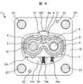
- FIG. 1 is a diagram showing a basic configuration of a gear pump according to a first embodiment of the present invention, and is a cross-sectional view perpendicular to a drive shaft.
- 2 is a cross-sectional view taken along line AA of the gear pump shown in FIG. 1
- FIG. 3 is a cross-sectional view taken along line EE of the gear pump shown in FIG. 2
- FIG. 4 is a cross-sectional view taken along line BB of the gear pump shown in FIG.
- FIG. 2 is a CC cross-sectional view of the gear pump shown in FIG. 1 corresponds to a DD sectional view of the gear pump shown in FIG.
- the gear pump 1 includes a pump assembly 10.
- the pump assembly 10 includes a drive shaft (drive shaft) 2, a driven shaft (driven shaft) 3, a pair of gears 4 and 5, a drive pin 6, a pair of side plates 7 and 7 ′, and a seal block 8. Is provided.
- the drive shaft 2 is connected to an external drive source (not shown) and is driven to rotate.
- the driven shaft 3 is rotated by a rotational force applied from the drive shaft 2 via a pair of gears 4 and 5.
- the pair of gears 4 and 5 are respectively supported by the drive shaft 2 and the driven shaft 3, and the tooth tips mesh with each other.
- the drive pin 6 is inserted into both the shafts 2 and 3 so that the drive shaft 2, the driven shaft 3 and the gears 4 and 5 rotate together.
- the pair of side plates 7 and 7 ' are disposed adjacent to both side surfaces of the gears 4 and 5, and as shown in FIG. Have. As shown in FIG.
- the seal block 8 is in contact with the side plates 7 and 7 ′ at the contact surface 21, and covers a part of the gears 4 and 5 in the circumferential direction as shown in FIGS. That is, the seal block 8 is close to the tooth tips of the gears 4 and 5 within a certain range in the circumferential direction of the gears 4 and 5.
- the side plate 7 is disposed adjacent to the side surface 4 a ′ of the gear 4 and the side surface 5 a ′ of the gear 5, and the side plate 7 ′ is connected to the side surface 4 a of the gear 4 and the side surface 5 a of the gear 5. Adjacent to each other.
- the side plate 7 is in sliding contact with the side surfaces 4 a ′ and 5 a ′ of the gears 4 and 5, and the side plate 7 ′ is in sliding contact with the side surfaces 4 a and 5 a of the gears 4 and 5. Seal the face.
- the through hole also functions as a bearing.
- the side plates 7 and 7 ′ have substantially the same shape, and have a suction port 19 that serves as a suction hole as shown in FIG. 1. Further, as shown in FIG. 3, the shape of the outer edges of the side plates 7, 7 ′ in the vicinity of the suction port 19 is substantially the same as the outer shape of the circle formed by the tooth tips of the gears 4, 5. That is, the shape of the outer edge of the side plates 7 and 7 ′ in the vicinity of the suction port 19 is an arc shape.
- the side surfaces of the seal block 8 facing the gears 4 and 5 have substantially the same shape as the arc-shaped portions of the side plates 7 and 7 '. As described above, the seal block 8 and the side plates 7 and 7 ′ are in close contact with each other at the contact surface 21 of the side plates 7 and 7 ′.
- the pump assembly 10 is accommodated in a housing 13 including a front case 11 and a rear case 12 as shown in FIG.
- the front case 11 and the rear case 12 are made of different members from the seal block 8.
- the rear case 12 has a recess 12a.
- a space for sealing the liquid is formed by attaching the front case 11 to the open end of the recess 12 a.
- the pump assembly 10 is provided with seal members 9 and 9 ′ on both end surfaces in the extending direction of the drive shaft 2. It is pinched by the rear case 12.
- the front case 11 and the rear case 12 are aligned with each other by a knock pin 22 shown in FIG.
- the recess 12a of the rear case has, for example, the shape shown in FIGS. 1 and 3. As shown in FIGS. 1 to 5, a part of the drive shaft 2, the driven shaft 3, the gears 4 and 5, the side plate 7, 7 'and the seal block 8 are accommodated.
- the surface 12b of the recess 12a of the rear case facing the seal block 8 is a cylindrical surface.
- a surface 8a facing the recess 12a of the rear case of the seal block 8 is also a cylindrical surface.
- the surface 12b of the rear case recess 12a facing the seal block 8 is referred to as a “rear case recess facing surface 12b”
- the surface 8a of the seal block 8 facing the rear case recess 12a is referred to as “the seal block facing surface”. 8a ".
- the facing surface 12b of the rear case recess and the facing surface 8a of the seal block face each other.
- the facing surface 12b of the rear case recess is a cylindrical surface having the same curvature as the facing surface 8a of the seal block or having a larger curvature than the facing surface 8a of the seal block.
- the pump assembly 10 rotates around the rotation axis with a straight line passing through the center of the arc of the opposing surface 12b of the rear case recess being a cylindrical surface and parallel to the drive shaft 2 as a rotation axis.
- the facing surface 12b of the rear case recess and the facing surface 8a of the seal block are in contact with each other at least at two locations, so that the pump assembly 10 is constrained to be rotatable around the rotation shaft.
- the rotation axis of the pump assembly 10 passes through the arc center of the facing surface 12b of the rear case recess and is parallel to the drive shaft 2. Accordingly, the rotation axis of the pump assembly 10 in FIG. 1 is located between the position of the drive shaft 2 and the position of the driven shaft 3 in the direction connecting the drive shaft 2 and the driven shaft 3 (left and right direction in FIG. 1). In the direction connecting the drive shaft 2 and the driven shaft 3 and the direction perpendicular to the extending direction of the drive shaft 2 (up and down direction in FIG. 1), it is located below the facing surface 8a of the seal block.
- the recess 12a of the rear case 12 is provided with a protruding portion 12c at one location on the inner wall.
- the projecting portion 12 c has a rotational axis of the pump assembly 10 with respect to the drive shaft 2 in the direction connecting the drive shaft 2 and the driven shaft 3 (the left-right direction in FIGS. 1 and 3). Is provided on the opposite side of the drive shaft 2, that is, on the lower left side of the drive shaft 2.
- the protrusion 12c contacts one of the two side plates 7 and 7 ′ (the side plate 7 ′ far from the front case 11 in FIG. 4), and the pump assembly 10 has been described above. Suppresses rotation around the rotation axis.
- the side plate 7 ′ has a portion on the opposite side of the rotational axis of the pump assembly 10 with respect to the drive shaft 2 in the direction connecting the drive shaft 2 and the driven shaft 3 (left and right direction in FIGS. 1 and 3).
- the rear case 12 is in contact with the protrusion 12c of the recess 12a.
- urging mechanisms 14a and 14b are provided to press the side plates 7 and 7 'in the direction in which the seal block 8 is located.
- the urging mechanisms 14a and 14b are elastic bodies, and are constituted by, for example, springs and pins. As shown in FIGS. 1 and 5, the urging mechanisms 14a and 14b are disposed between the side plates 7 and 7 'and the inner wall of the rear case recess 12a.
- the urging mechanism 14 a is disposed so as to press the side plate 7 ′ and rotate the pump assembly 10 in the same direction as the rotation direction R ⁇ b> 1 of the drive shaft 2 and the gear 4. That is, the urging mechanism 14a is located at the position of the protrusion 12c (left side in FIG. 3) with respect to the rotation axis of the pump assembly 10 in the direction connecting the drive shaft 2 and the driven shaft 3 (left and right direction in FIG. 3). Is disposed on the opposite side (right side in FIG. 3) and presses the side plate 7 ′. As described above, the side plate 7 ′ is supported by the protruding portion 12 c of the recess 12 a of the rear case 12.
- the urging mechanism 14 b is configured so that the pump assembly 10 can move in a direction (vertical direction in FIG. 3) perpendicular to the direction connecting the drive shaft 2 and the driven shaft 3 and the extending direction of the drive shaft 2. It arrange
- the pump assembly 10 is housed in the recess 12a of the rear case 12 so as to be rotatable around the rotation axis.
- the rotation of the pump assembly 10 is suppressed by the urging mechanism 14 a pressing the side plate 7 ′ against the protrusion 12 c of the recess 12 a of the rear case 12.
- the position of the pump assembly 10 within the recess 12a of the rear case 12 is determined.
- the position of the side plate 7 is fixed in a state where the side plate 7 is not in contact with the recess 12 a of the rear case 12 but is pressed by the urging mechanism 14 b and is in close contact with the seal block 8 at the contact surface 21.
- the one side plate 7 ′ plays a role of fixing the position of the pump assembly 10, and the other side plate 7 is fixed by contacting the fixed seal block 8. For this reason, even if the shape of the contact surface 21 with the seal block 8 is slightly different between the two side plates 7 and 7 ′ due to processing errors, one side plate is different between the other side plate and the seal block 8. Adhesion is not hindered.
- the front case 11 has a groove 15 on a contact surface with the rear case 12.
- a case seal 16 is disposed in the groove 15.
- the front case 11 is attached to the rear case 12 in such a state.
- the case seal 16 seals a gap that may be generated between the front case 11 and the rear case 12 to prevent the liquid in the rear case 12 from leaking to the outside.
- the front case 11 is provided with a recess 17 on the surface opposite to the contact surface with the rear case 12 (for example, the lower surface in FIG. 2).
- An oil seal 18 is disposed in the recess 17.
- the oil seal 18 is press-fitted into the recess 17 of the front case 11, the outer peripheral surface is in close contact with the wall surface of the recess 17, and the inner peripheral surface is in sliding contact with the outer peripheral surface of the drive shaft 2.
- the oil seal 18 seals a gap formed between the drive shaft 2 and the front case 11 so that the liquid in the pump chamber does not leak to the outside when the gear pump is driven.
- the suction port 19 is formed by the side plates 7, 7 ′, the seal block 8, and the rear case 12. Further, the discharge port 20 is formed by the flow path formed in the rear case 12. As shown in FIGS. 1, 3, and 5, the discharge port 20 communicates with the recess 12 a of the rear case 12.
- a tank (not shown) for supplying liquid to the gear pump 1 is connected upstream of the suction port 19.
- a valve, a cylinder (not shown) or the like is connected downstream of the discharge port 20 to adjust the pump discharge pressure.
- the drive shaft 2 is connected to a drive source (not shown) such as a motor.
- the gear pump 1 When the gear pump 1 is driven, a high pressure region and a low pressure region are formed in the recess 12a of the rear case 12.
- the high pressure region and the low pressure region are partitioned by each component described below.
- the seal by each of these parts will be described.
- the gear pump 1 includes a meshing portion of the gears 4 and 5, a sliding contact surface between the tooth tips of the gears 4 and 5 and the seal block 8, side surfaces 4 a, 4 a ′, 5 a, 5 a ′ and side plates 7, 7 ′. , A contact surface between the seal block 8 and the side plates 7 and 7 ′, and seal members 9 and 9 ′ installed between the end surface of the pump assembly 10 and the front case 11 and the rear case 12.
- the liquid is partitioned and sealed so that the liquid does not communicate when a differential pressure is generated around the suction port 19 and the discharge port 20.
- the drive shaft 2 is driven by a drive source such as a motor (not shown) as described above.
- the gear 4 is supported so as to rotate integrally with the drive shaft 2. For this reason, when the drive shaft 2 rotates in the rotation direction R1 shown in FIG. 3, the gear 4 also rotates in the rotation direction R1.
- the gear 5 meshes with the gear 4 and the tooth tips, and rotates together with the driven shaft 3. For this reason, when the gear 4 rotates in the rotation direction R1, the gear 5 rotates together with the driven shaft 3 in the rotation direction R2.
- Rotating the gears 4 and 5 with disengaged teeth separates the volume of the space around the suction port 19, and as a result, liquid is sucked from the suction port 19.
- the liquid around the suction port 19 is accommodated in the tooth spaces of the gears 4 and 5 by the rotation of the gears 4 and 5 and conveyed along the rotation directions R1 and R2 of the gears 4 and 5.
- the conveyed liquid flows out of the tooth gap as the gears 4 and 5 rotate.
- liquid does not communicate between the periphery of the suction port 19 and the periphery of the discharge port 20 of the gear pump 1 by the seal of each component. For this reason, the pressure rises around the discharge port 20 due to the liquid flowing out of the tooth gap, and the liquid is discharged from the discharge port 20.
- the gear pump 1 has a low pressure only inside the seal members 9 and 9 ', and the other portions have a high pressure.
- the pump assembly 10 is fixed to the recess 12a of the rear case 12 by the method described above.
- the pump assembly 10 is moved to the rear case 12 by the influence of the meshing reaction force of the gears 4 and 5 and the influence of the frictional force between the side surfaces of the gears 4 and 5 and the side plates 7 and 7 '.
- the recess 12a In the recess 12a, a force to rotate in the same direction as the rotation direction R1 of the drive shaft 2 is received.
- the facing surface 12b of the rear case recess and the facing surface 8a of the seal block are in contact with each other in at least two places, and the protruding portion 12c of the recess 12a of the rear case 12 and one side plate 7 ′ are 1 Touching at a point.
- the pump assembly 10 contacts the rear case 12 at at least three locations. For this reason, the pump assembly 10 can be stably fixed to the recess 12 a of the rear case 12.
- the position where the side plate 7 ′ contacts the rear case 12, that is, the position of the protrusion 12 c is as far as possible from the rotational axis of the pump assembly 10 (for example, in FIG. 1, as far as the lower left of the recess 12 a of the rear case 12.
- the position of the inner wall is preferable because stability during operation is increased.
- the position of the pump assembly 10 is determined by the method described above. For this reason, the bearings for supporting the drive shaft 2 and the driven shaft 3 do not need to be provided in the front case 11 and the rear case 12, and may be provided only in the side plates 7 and 7 '(as described above, the side plate 7 , 7 ′ has a through hole as a bearing).
- the drive shaft 2 is not excessively constrained by providing bearings in the front case 11 and the rear case 12. Further, measures are taken to avoid over-constraint, for example, the clearance between the bearings of the side plates 7 and 7 ′ and the drive shaft 2 is made larger than the clearance between the bearings of the front case 11 and the rear case 12 and the drive shaft 2. There is no need. Further, since the drive shaft 2 and the driven shaft 3 are supported by bearings on the side plates 7 and 7 ′ adjacent to the gears 4 and 5, the shaft deflection due to pressure can be suppressed to a small level when the gear pump 1 is driven. At the time of high-pressure discharge, the amount of gear 4 and 5 tooth tips that slide with the seal block 8 can be reduced.
- the gear pump 1 according to the present embodiment does not require a bearing to be installed in the housing 13 as described above. Therefore, the assembly of the pump assembly 10, the front case 11, and the rear case 12 does not require high accuracy, and the pump assembly 10 is configured. A high-efficiency pump can be realized simply by considering the processing accuracy of the parts to be processed. For this reason, the gear pump 1 of a present Example is easy to assemble and can reduce cost.
- the opposing surface 12b of the rear case recess and the opposing surface 8a of the seal block are cylindrical surfaces, but these surfaces may not be cylindrical surfaces.
- An example in which the opposed surface 12b of the rear case recess and the opposed surface 8a of the seal block are not cylindrical surfaces will be described with reference to FIGS. 6 to 8, the same reference numerals as those in FIGS. 1 to 5 denote the same or common elements as in FIGS. 1 to 5, and the description of these elements is omitted.
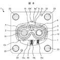
- FIG. 6 is a cross-sectional view perpendicular to the drive shaft 2 of the gear pump 1 (a cross-sectional view at the same position as shown in FIG. 1), and an example in which the facing surface 12b ′ of the rear case recess is not a cylindrical surface.
- FIG. The opposing surface 12 b ′ of the rear case recess of the gear pump 1 shown in FIG. 6 has a shape composed of two planes forming a V shape, and protrudes from the seal block 8 toward the outside of the rear case 12.
- the opposing surface 8a of the seal block is a cylindrical surface.
- the opposing surface 12b ′ of the rear case recess has such a shape, the opposing surface 12b ′ of the rear case recess and the opposing surface 8a of the seal block come into contact with each other at least at two locations. Restrained to rotate around. However, the rotation axis in this case is a straight line passing through the center of the circular arc of the cylindrical surface inscribed in the facing surface 12b 'of the rear case recess and parallel to the drive shaft 2. Therefore, even with the configuration shown in FIG. 6, the same effects as the configurations shown in FIGS. 1 to 5 can be obtained.
- FIG. 7 is a cross-sectional view perpendicular to the drive shaft 2 of the gear pump 1 (a cross-sectional view at the same position as shown in FIG. 1), and shows an example in which the facing surface 8a ′ of the seal block is not a cylindrical surface.
- FIG. The opposing surface 8a 'of the seal block of the gear pump 1 shown in FIG. 7 has a planar shape and contacts the opposing surface 12b of the rear case recess at the end of the plane.
- the facing surface 8a ′ of the seal block has such a shape, the facing surface 12b of the rear case recess and the facing surface 8a ′ of the seal block are in contact with each other at least in two places. It is constrained to be rotatable. Therefore, even with the configuration shown in FIG. 7, the same effect as the configuration shown in FIGS. 1 to 5 can be obtained.
- FIG. 8 is a cross-sectional view perpendicular to the drive shaft 2 of the gear pump 1 (a cross-sectional view at the same position as shown in FIG. 1), and the opposing surface 12b ′ of the rear case recess and the opposing surface 8a ′′ of the seal block. It is a figure which shows the example of the shape which is not a cylindrical surface.
- the opposing surface 12b 'of the rear case recess of the gear pump 1 shown in FIG. 8 has a shape composed of two planes forming a V-shape, as in FIG.
- the opposing surface 8a '' of the seal block of the gear pump 1 shown in FIG. 8 has a shape composed of three planes, and is located between the two planes that contact the opposing surface 12b 'of the rear case recess and these planes. And one plane.
- the opposing surface 12b ′ of the rear case recess and the opposing surface 8a ′′ of the seal block have such a shape, the opposing surface 12b ′ of the rear case recess and the opposing surface 8a ′′ of the seal block contact each other at least in two places.
- the pump assembly 10 is constrained to be rotatable about the rotation axis.
- the rotation axis in this case is a straight line passing through the center of the circular arc of the cylindrical surface inscribed in the facing surface 12b 'of the rear case recess and parallel to the drive shaft 2. Therefore, even with the configuration shown in FIG. 8, the same effect as the configuration shown in FIGS. 1 to 5 can be obtained.
- the shape of the facing surface of the rear case recess and the facing surface of the seal block may not be a cylindrical surface but may be a shape including a flat surface.
- the shape containing curved surfaces other than a cylindrical surface may be sufficient.
- the opposing surface of the seal block may have a shape composed of two curved surfaces that come into contact with the opposing surface of the rear case recess and one flat surface located between these curved surfaces. That is, the opposing surface of the rear case recess and the opposing surface of the seal block are surfaces including one or both of a curved surface and a flat surface.
- the opposing surface of the rear case concave portion is formed only by a flat surface, in order to constrain the pump assembly 10 to be rotatable around the rotation axis, for example, as shown in FIGS.
- the opposing surface needs to be formed by a plurality of planes.
- the pump assembly 10 is constrained to be rotatable around the rotation axis when the opposed surface of the rear case recess and the opposed surface of the seal block come into contact with each other in at least two places.
- the rotation axis of the pump assembly 10 is a straight line passing through the center of the circular arc of the cylindrical surface inscribed in the opposing surface of the rear case recess and parallel to the drive shaft 2. Since the protrusion 12c of the recess 12a of the rear case 12 and the side plate 7 'are in contact with each other, the rotation of the pump assembly 10 is suppressed. Thus, since the pump assembly 10 contacts the rear case 12 at at least three locations, the pump assembly 10 can be stably fixed to the recess 12a of the rear case 12.
- the protrusion 12c of the recess 12a of the rear case 12 is directly processed on the rear case 12, but may be provided on the rear case 12 by other methods.
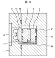
- FIG. 9 is a cross-sectional view taken along the line BB of the gear pump shown in FIG. 1 in the same manner as FIG. 4, and is a diagram showing an example of how to provide the protruding portion of the recess 12a of the rear case 12 by another method.
- the same reference numerals as those in FIGS. 1 to 5 denote the same or common elements as those in FIGS. 1 to 5, and the description of these elements will be omitted.
- the rotation stop pin 24 is press-fitted as a separate part into the front case 11 and the rear case 12 and functions as a protruding portion of the recess 12 a of the rear case 12. Since the rotation stop pin 24 is in contact with the side plate 7 ', even with this configuration, the same effect as the configuration shown in FIGS. 1 to 5 can be obtained.
- the protrusion of the recess 12a of the rear case 12 be located as far as possible from the rotation axis of the pump assembly 10.
- the protrusion of the recess 12a of the rear case 12 only needs to be provided at a position where the rotation of the pump assembly 10 can be stopped, and if it is such a position, it can be provided at any part of the recess 12a of the rear case. Almost the same effect can be obtained.
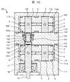
- FIG. 10 is a diagram showing the configuration of the gear pump according to the second embodiment of the present invention, and is a cross-sectional view in a direction parallel to the drive shaft (drive shaft).
- the gear pump 101 according to the second embodiment has a configuration in which two gear pumps 1 according to the first embodiment are arranged in series and are driven by a single drive source. 10 corresponds to the AA cross section of FIG. 1, as in FIG.
- the sectional view other than the section shown in FIG. 10 and the configuration of the pump assembly are the same as those in the first embodiment.
- the same or common elements as in the first embodiment are denoted by the same reference numerals as those used in the first embodiment, and detailed description thereof is omitted.
- the gear pump 101 includes two pump assemblies 110 and 110 '.
- the pump assemblies 110 and 110 ' have the same configuration as the pump assembly 10 shown in the first embodiment, and are arranged in series in the extending direction of the drive shaft.
- the gear pump 101 has a front case 111 and a rear case 112.
- the front case 111 and the rear case 112 have recesses 111a and 112a, respectively.
- the recesses 111a and 112a have the same shape as the recess 12a of the rear case 12 shown in the first embodiment, and store the pump assemblies 110 and 110 ', respectively.
- the gear pump 101 further includes a center plate 150.
- the center plate 150 is attached to the open ends of the front case 111 and the rear case 112, and includes a groove 115 on the contact surface with the front case 111 and a groove 115 'on the contact surface with the rear case 112.
- the groove portions 115 and 115 ′ have the same shape as the groove portion 15 of the front case 11 of the first embodiment.
- Case seals 116 and 116 ' are installed in the grooves 115 and 115', respectively.
- the housing 113 includes a front case 111, a rear case 112, and a center plate 150.
- the front case 111, the rear case 112, and the center plate 150 are joined together by fastening with bolts or welding.
- the pump assemblies 110 and 110 ' are driven by a common drive source. Instead of the drive shaft 2 shown in the first embodiment, the pump assembly 110 is driven by the front drive shaft 151 and the pump assembly 110 ′ is driven by the rear drive shaft 152.
- the center plate 150 has a through hole 153, and the joint part 154 is accommodated in the through hole 153.
- the joint portion 154 includes a joint shaft 155 and connects the front drive shaft 151 and the rear drive shaft 152.
- the joint shaft 155 transmits the driving force of a driving source (not shown) connected to the tip of the front drive shaft 151 to the rear drive shaft 152.
- a universal joint can be used for the joint portion 154.
- a joint pin 156 is inserted into the front drive shaft 151, and a joint pin 156 'is inserted into the rear drive shaft 152.
- FIG. 11 is a view showing the front drive shaft 151, the rear drive shaft 152, and the joint portion 154 shown in FIG. 11, the same reference numerals as those in FIG. 10 indicate the same or common elements as those in FIG. 11, and description of these elements is omitted.
- the joint pin 156 inserted into the front drive shaft 151 is illustrated as being pulled out for the sake of explanation.
- the joint portion 154 can transmit the power of the drive source from the front drive shaft 151 to the rear drive shaft 152 by the joint shaft 155 and the joint pins 156 and 156 ′. is there.
- a hole 151 a is provided at the end of the front shaft 151, and a hole 152 a is provided at the end of the rear shaft 152.
- the tip of the joint shaft 155 enters the hole 151a and the hole 152a.
- the inner diameters of the hole 151a and the hole 152a are larger than the outer diameter of the joint shaft 155.
- the joint shaft 155 can be tilted around the joint pins 156 and 156 ′ within the gap between the joint shaft 155 and the holes 151 a and 152 a.
- the joint portion 154 includes a joint collar 157, a joint seal 158, and a joint washer 159.
- the joint collar 157 is in sliding contact with the outer periphery of the joint shaft 155 and is installed so as not to rotate with respect to the center plate 150.
- the joint seal 158 is disposed in contact with the outer periphery of the joint collar 157 and the inner periphery of the through hole 153 of the center plate 150.
- the joint washer 159 constitutes a wall surface of the joint seal 158.
- the pump assembly 110 is housed in the recess 111a of the front case 111 so as to be rotatable around the rotation axis, and at least 3 It contacts the front case 111 at a location.
- the pump assembly 110 ′ is housed in the recess 112 a of the rear case 112 so as to be rotatable around the rotation axis, and contacts the rear case 112 at least at three locations. For this reason, the pump assembly 110 and the pump assembly 110 ′ can be stably fixed to the recess 111 a of the front case 111 and the recess 112 a of the rear case 112, respectively.
- the rotation axes of the pump assembly 110 and the pump assembly 110 ' can be determined in the same manner as the rotation axis of the pump assembly 10 described in the first embodiment.
- the joint portion 154 as described above can absorb the coaxial displacement between the front drive shaft 151 and the rear drive shaft 152, and can transmit only torque from the front drive shaft 151 to the rear drive shaft 152. Mechanism. For this reason, the gear pump 101 according to the second embodiment does not require high accuracy for assembly, like the gear pump 1 shown in the first embodiment.
- the gear pump 101 in which two pump assemblies of the first embodiment are connected in series can drive both pump assemblies 110 and 110 'with high efficiency.
- the gear pump 101 does not need to increase the assembly accuracy between the pump assembly 110 and the front case 111 and the assembly accuracy between the pump assembly 110 ′ and the rear case 112.
- the efficiency of the gear pump can be increased by increasing only the processing accuracy of the parts constituting the pump assemblies 110 and 110 ′. For this reason, the gear pump 101 is easy to assemble, and it is possible to improve the yield and reduce the cost.
- each pump assembly is connected by a joint portion 154, thereby achieving high efficiency.
- a simple pump can be realized.
- a connecting portion having the same structure as the joint portion 154 may be installed between the driving source of the front drive shaft 151 and the front drive shaft 151.
- front drive shaft 151a ... hole, 152 ... rear drive shaft, 152a ... hole, 153 ... through hole, 154 ... joint portion, 155 ... joint shaft, 156, 156 '... joint pin, 157 ... joint collar, 158 ... joint seal, 159 ... joint washer.
Landscapes
- Engineering & Computer Science (AREA)
- Mechanical Engineering (AREA)
- General Engineering & Computer Science (AREA)
- Rotary Pumps (AREA)
- Details And Applications Of Rotary Liquid Pumps (AREA)
Description
Claims (10)
- 互いに噛み合う一対のギヤと、
回転可能に支持され、前記一対のギヤのそれぞれに挿入され、前記一対のギヤと共に回転する2つの軸と、
前記一対のギヤの両側面に隣接して配置され、前記2つの軸の軸受となる2つの貫通穴をそれぞれが有する一対の側板と、
前記一対の側板と当接し、前記一対のギヤの円周方向の一部を覆うシールブロックと、
前記一対のギヤ、前記2つの軸、前記一対の側板、及び前記シールブロックを備えるポンプ組立体と、
前記ポンプ組立体を収容する凹部を有し、前記凹部を形成する内壁に前記シールブロックと対向する対向面を有するケースと、
を備えるギヤポンプであって、
前記ポンプ組立体は、前記ケースの前記対向面に内接する円筒面の円弧中心を通り前記2つの軸に平行な直線を回転軸とし、前記回転軸の回りに回転可能に拘束され、前記回転軸の回りに回転すると、前記一対の側板の一方が前記ケースの内壁と接触する、
ことを特徴とするギヤポンプ。 - 前記ポンプ組立体は、前記シールブロックと前記ケースの前記対向面とが少なくとも2箇所で互いに接触することで、前記回転軸の回りに回転可能に拘束される請求項1記載のギヤポンプ。
- 前記2つの軸のうち、一方は駆動源により回転する駆動軸であり、他方は前記一対のギヤを介して前記駆動軸から回転力が与えられて回転する従動軸であり、
前記一対の側板の一方は、前記ポンプ組立体が前記回転軸の回りに回転すると、前記2つの軸を結ぶ方向において前記駆動軸に対して前記回転軸とは反対側にある部分が、前記ケースの内壁と接触する、請求項1または2記載のギヤポンプ。 - 前記2つの軸のうち、一方は駆動源により回転する駆動軸であり、他方は前記一対のギヤを介して前記駆動軸から回転力が与えられて回転する従動軸であり、
前記ケースは、内壁のうち、前記2つの軸を結ぶ方向において前記駆動軸に対して前記回転軸とは反対側にある部分に突出部を有し、
前記一対の側板の一方は、前記ポンプ組立体が前記回転軸の回りに回転すると、前記ケースの内壁の前記突出部と接触する、請求項1または2記載のギヤポンプ。 - 前記一対の側板の他方は、前記ケースに接触せず、前記シールブロックに接触して固定される請求項1または2記載のギヤポンプ。
- 前記ケースの前記凹部に、前記一対の側板の一方を押圧して、前記ポンプ組立体を前記駆動軸の回転方向と同じ方向に回転させるための弾性体を備える請求項5記載のギヤポンプ。
- 前記ケースの前記凹部に、前記一対の側板の他方を押圧して、前記一対の側板の他方と前記シールブロックと密着させるための弾性体を備える請求項5記載のギヤポンプ。
- 前記2つの軸の軸受を、前記一対の側板にのみ有する請求項1または2記載のギヤポンプ。
- 複数のポンプ組立体と、前記複数のポンプ組立体をそれぞれ収容する複数のケースとを備え、
前記複数のポンプ組立体のそれぞれは、
互いに噛み合う一対のギヤと、
回転可能に支持され、前記一対のギヤのそれぞれに挿入され、前記一対のギヤと共に回転し、一方が駆動軸である2つの軸と、
前記一対のギヤの両側面に隣接して配置され、前記2つの軸の軸受となる2つの貫通穴をそれぞれが有する一対の側板と、
前記一対の側板と当接し、前記一対のギヤの円周方向の一部を覆うシールブロックと、
を備え、
前記複数のケースのそれぞれは、前記ポンプ組立体を収容する凹部を有し、前記凹部を形成する内壁に前記シールブロックと対向する対向面を有し、
前記複数のポンプ組立体は、前記駆動軸同士が接続されているギヤポンプであって、
前記複数のポンプ組立体のそれぞれは、前記ケースの前記対向面に内接する円筒面の円弧中心を通り前記2つの軸に平行な直線を回転軸とし、前記回転軸の回りに回転可能に拘束され、前記回転軸の回りに回転すると、前記一対の側板の一方が前記ケースの内壁と接触する、
ことを特徴とするギヤポンプ。 - 前記複数のポンプ組立体は、前記駆動軸のトルクのみを伝達し同軸ずれを吸収するトルク伝達機構によって、前記駆動軸同士が接続されている請求項9記載のギヤポンプ。
Priority Applications (6)
| Application Number | Priority Date | Filing Date | Title |
|---|---|---|---|
| US14/410,357 US9644627B2 (en) | 2012-06-28 | 2012-06-28 | Gear pump |
| EP12880055.4A EP2868925B1 (en) | 2012-06-28 | 2012-06-28 | Gear pump |
| KR1020147027537A KR101659362B1 (ko) | 2012-06-28 | 2012-06-28 | 기어 펌프 |
| CN201280073855.6A CN104364528B (zh) | 2012-06-28 | 2012-06-28 | 齿轮泵 |
| PCT/JP2012/066515 WO2014002225A1 (ja) | 2012-06-28 | 2012-06-28 | ギヤポンプ |
| JP2014522303A JP5798250B2 (ja) | 2012-06-28 | 2012-06-28 | ギヤポンプ |
Applications Claiming Priority (1)
| Application Number | Priority Date | Filing Date | Title |
|---|---|---|---|
| PCT/JP2012/066515 WO2014002225A1 (ja) | 2012-06-28 | 2012-06-28 | ギヤポンプ |
Publications (1)
| Publication Number | Publication Date |
|---|---|
| WO2014002225A1 true WO2014002225A1 (ja) | 2014-01-03 |
Family
ID=49782456
Family Applications (1)
| Application Number | Title | Priority Date | Filing Date |
|---|---|---|---|
| PCT/JP2012/066515 Ceased WO2014002225A1 (ja) | 2012-06-28 | 2012-06-28 | ギヤポンプ |
Country Status (6)
| Country | Link |
|---|---|
| US (1) | US9644627B2 (ja) |
| EP (1) | EP2868925B1 (ja) |
| JP (1) | JP5798250B2 (ja) |
| KR (1) | KR101659362B1 (ja) |
| CN (1) | CN104364528B (ja) |
| WO (1) | WO2014002225A1 (ja) |
Cited By (1)
| Publication number | Priority date | Publication date | Assignee | Title |
|---|---|---|---|---|
| KR101687333B1 (ko) * | 2015-07-21 | 2016-12-16 | (주)씨에스이 | 기어펌프 어셈블리 |
Families Citing this family (5)
| Publication number | Priority date | Publication date | Assignee | Title |
|---|---|---|---|---|
| CN106640642A (zh) * | 2016-11-16 | 2017-05-10 | 天津商业大学 | 带弹性接触密封的双螺杆制冷压缩机 |
| DE102017110394B3 (de) | 2017-05-12 | 2018-06-28 | Schaeffler Technologies AG & Co. KG | Elektrischer Pumpenaktuator, stufenloses Getriebe mit elektrischen Pumpenaktuator und Steuerungsverfahren für elektrischen Pumpenaktuator |
| US10858939B2 (en) * | 2018-07-20 | 2020-12-08 | Hamilton Sundstrand Corporation | Gear pump bearings |
| US10731701B2 (en) * | 2018-07-23 | 2020-08-04 | Hamilton Sunstrand Corporation | High efficiency gear pump bearing assembly |
| CN109356845B (zh) * | 2018-10-09 | 2023-06-23 | 宿迁学院 | 一种齿轮泵用的无轴向泄漏装置 |
Citations (4)
| Publication number | Priority date | Publication date | Assignee | Title |
|---|---|---|---|---|
| JPH1193792A (ja) | 1997-09-18 | 1999-04-06 | Hitachi Ltd | 車両用エンジンの燃料供給装置および燃料ポンプ |
| JP2000009054A (ja) * | 1998-06-25 | 2000-01-11 | Hitachi Ltd | 歯車ポンプおよび燃料供給装置と歯車モータ |
| JP2002202070A (ja) | 2000-12-28 | 2002-07-19 | Tokico Ltd | ギヤポンプ |
| JP2005188372A (ja) * | 2003-12-25 | 2005-07-14 | Hitachi Ltd | ギヤポンプ |
Family Cites Families (10)
| Publication number | Priority date | Publication date | Assignee | Title |
|---|---|---|---|---|
| US3041974A (en) * | 1956-05-25 | 1962-07-03 | Borg Warner | Pumps |
| DE1134590B (de) * | 1957-11-09 | 1962-08-09 | Bosch Gmbh Robert | Zahnradpumpe |
| DE1553030A1 (de) * | 1965-10-12 | 1975-06-19 | Otto Eckerle | Spiel- und verschleissausgleichende hochdruck-zahnradpumpe bzw. -motor |
| DE3938135A1 (de) * | 1989-11-16 | 1991-05-23 | Bosch Gmbh Robert | Zahnradpumpe |
| JP3932595B2 (ja) * | 1997-03-12 | 2007-06-20 | 株式会社日立製作所 | ギヤポンプ |
| JP4611786B2 (ja) * | 2004-04-30 | 2011-01-12 | 日立オートモティブシステムズ株式会社 | ギヤポンプ及びその製造方法 |
| WO2007136028A1 (ja) * | 2006-05-22 | 2007-11-29 | Hitachi, Ltd. | ギヤポンプおよびその製造方法 |
| JP4789849B2 (ja) | 2006-05-22 | 2011-10-12 | 日立オートモティブシステムズ株式会社 | ギヤポンプおよびその製造方法 |
| US7717690B2 (en) * | 2006-08-15 | 2010-05-18 | Tbk Co., Ltd. | Gear pump |
| DE102006041633A1 (de) * | 2006-09-05 | 2008-03-13 | Herold & Co. Gmbh | Pumpe |
-
2012
- 2012-06-28 JP JP2014522303A patent/JP5798250B2/ja not_active Expired - Fee Related
- 2012-06-28 EP EP12880055.4A patent/EP2868925B1/en not_active Not-in-force
- 2012-06-28 US US14/410,357 patent/US9644627B2/en not_active Expired - Fee Related
- 2012-06-28 CN CN201280073855.6A patent/CN104364528B/zh not_active Expired - Fee Related
- 2012-06-28 KR KR1020147027537A patent/KR101659362B1/ko not_active Expired - Fee Related
- 2012-06-28 WO PCT/JP2012/066515 patent/WO2014002225A1/ja not_active Ceased
Patent Citations (4)
| Publication number | Priority date | Publication date | Assignee | Title |
|---|---|---|---|---|
| JPH1193792A (ja) | 1997-09-18 | 1999-04-06 | Hitachi Ltd | 車両用エンジンの燃料供給装置および燃料ポンプ |
| JP2000009054A (ja) * | 1998-06-25 | 2000-01-11 | Hitachi Ltd | 歯車ポンプおよび燃料供給装置と歯車モータ |
| JP2002202070A (ja) | 2000-12-28 | 2002-07-19 | Tokico Ltd | ギヤポンプ |
| JP2005188372A (ja) * | 2003-12-25 | 2005-07-14 | Hitachi Ltd | ギヤポンプ |
Non-Patent Citations (1)
| Title |
|---|
| See also references of EP2868925A4 |
Cited By (1)
| Publication number | Priority date | Publication date | Assignee | Title |
|---|---|---|---|---|
| KR101687333B1 (ko) * | 2015-07-21 | 2016-12-16 | (주)씨에스이 | 기어펌프 어셈블리 |
Also Published As
| Publication number | Publication date |
|---|---|
| KR101659362B1 (ko) | 2016-09-26 |
| KR20140131986A (ko) | 2014-11-14 |
| EP2868925A4 (en) | 2016-03-16 |
| EP2868925B1 (en) | 2018-08-08 |
| JP5798250B2 (ja) | 2015-10-21 |
| US20150337836A1 (en) | 2015-11-26 |
| EP2868925A1 (en) | 2015-05-06 |
| CN104364528A (zh) | 2015-02-18 |
| US9644627B2 (en) | 2017-05-09 |
| JPWO2014002225A1 (ja) | 2016-05-26 |
| CN104364528B (zh) | 2018-07-10 |
Similar Documents
| Publication | Publication Date | Title |
|---|---|---|
| JP5798250B2 (ja) | ギヤポンプ | |
| CN102562575B (zh) | 外啮合齿轮泵 | |
| JP4842341B2 (ja) | ギヤポンプ及びブレーキ装置用ギヤポンプ | |
| CN104704239B (zh) | 可变容量型叶片泵 | |
| CN107709781A (zh) | 泵装置 | |
| JP5164720B2 (ja) | 外接歯車ポンプ | |
| US8894396B2 (en) | Pump apparatus with pressing means | |
| US11560891B2 (en) | Electric hydraulic actuator | |
| KR20150070392A (ko) | 액압 회전기에 구비되는 피스톤 및 액압 회전기 | |
| JP4856137B2 (ja) | ギヤポンプ | |
| CN116085240A (zh) | 一种蠕动泵 | |
| JP5022323B2 (ja) | ギヤポンプ | |
| JP7001525B2 (ja) | 斜板式液圧回転機械 | |
| US20170335846A1 (en) | Gear Pump | |
| JP6153025B2 (ja) | ポンプ装置 | |
| US20140003981A1 (en) | Pump Device | |
| JP2013167159A (ja) | 外接歯車ポンプ | |
| JP5222758B2 (ja) | ギヤポンプ | |
| JP5106000B2 (ja) | 可変容量型ベーンポンプ | |
| JP2015169114A (ja) | ポンプ装置又はその製造方法 | |
| JP2008095606A (ja) | ギヤポンプ |
Legal Events
| Date | Code | Title | Description |
|---|---|---|---|
| 121 | Ep: the epo has been informed by wipo that ep was designated in this application |
Ref document number: 12880055 Country of ref document: EP Kind code of ref document: A1 |
|
| ENP | Entry into the national phase |
Ref document number: 20147027537 Country of ref document: KR Kind code of ref document: A |
|
| ENP | Entry into the national phase |
Ref document number: 2014522303 Country of ref document: JP Kind code of ref document: A |
|
| WWE | Wipo information: entry into national phase |
Ref document number: 2012880055 Country of ref document: EP |
|
| WWE | Wipo information: entry into national phase |
Ref document number: 14410357 Country of ref document: US |
|
| NENP | Non-entry into the national phase |
Ref country code: DE |