WO2014002429A1 - 電子写真用部材、プロセスカートリッジおよび電子写真装置 - Google Patents
電子写真用部材、プロセスカートリッジおよび電子写真装置 Download PDFInfo
- Publication number
- WO2014002429A1 WO2014002429A1 PCT/JP2013/003806 JP2013003806W WO2014002429A1 WO 2014002429 A1 WO2014002429 A1 WO 2014002429A1 JP 2013003806 W JP2013003806 W JP 2013003806W WO 2014002429 A1 WO2014002429 A1 WO 2014002429A1
- Authority
- WO
- WIPO (PCT)
- Prior art keywords
- structural formula
- group
- carbon atoms
- electrophotographic
- represented
- Prior art date
- Legal status (The legal status is an assumption and is not a legal conclusion. Google has not performed a legal analysis and makes no representation as to the accuracy of the status listed.)
- Ceased
Links
Images


Classifications
-
- G—PHYSICS
- G03—PHOTOGRAPHY; CINEMATOGRAPHY; ANALOGOUS TECHNIQUES USING WAVES OTHER THAN OPTICAL WAVES; ELECTROGRAPHY; HOLOGRAPHY
- G03G—ELECTROGRAPHY; ELECTROPHOTOGRAPHY; MAGNETOGRAPHY
- G03G15/00—Apparatus for electrographic processes using a charge pattern
- G03G15/06—Apparatus for electrographic processes using a charge pattern for developing
-
- G—PHYSICS
- G03—PHOTOGRAPHY; CINEMATOGRAPHY; ANALOGOUS TECHNIQUES USING WAVES OTHER THAN OPTICAL WAVES; ELECTROGRAPHY; HOLOGRAPHY
- G03G—ELECTROGRAPHY; ELECTROPHOTOGRAPHY; MAGNETOGRAPHY
- G03G15/00—Apparatus for electrographic processes using a charge pattern
- G03G15/06—Apparatus for electrographic processes using a charge pattern for developing
- G03G15/08—Apparatus for electrographic processes using a charge pattern for developing using a solid developer, e.g. powder developer
- G03G15/0806—Apparatus for electrographic processes using a charge pattern for developing using a solid developer, e.g. powder developer on a donor element, e.g. belt, roller
- G03G15/0818—Apparatus for electrographic processes using a charge pattern for developing using a solid developer, e.g. powder developer on a donor element, e.g. belt, roller characterised by the structure of the donor member, e.g. surface properties
-
- G—PHYSICS
- G03—PHOTOGRAPHY; CINEMATOGRAPHY; ANALOGOUS TECHNIQUES USING WAVES OTHER THAN OPTICAL WAVES; ELECTROGRAPHY; HOLOGRAPHY
- G03G—ELECTROGRAPHY; ELECTROPHOTOGRAPHY; MAGNETOGRAPHY
- G03G15/00—Apparatus for electrographic processes using a charge pattern
- G03G15/75—Details relating to xerographic drum, band or plate, e.g. replacing, testing
-
- G—PHYSICS
- G03—PHOTOGRAPHY; CINEMATOGRAPHY; ANALOGOUS TECHNIQUES USING WAVES OTHER THAN OPTICAL WAVES; ELECTROGRAPHY; HOLOGRAPHY
- G03G—ELECTROGRAPHY; ELECTROPHOTOGRAPHY; MAGNETOGRAPHY
- G03G15/00—Apparatus for electrographic processes using a charge pattern
- G03G15/02—Apparatus for electrographic processes using a charge pattern for laying down a uniform charge, e.g. for sensitising; Corona discharge devices
- G03G15/0208—Apparatus for electrographic processes using a charge pattern for laying down a uniform charge, e.g. for sensitising; Corona discharge devices by contact, friction or induction, e.g. liquid charging apparatus
- G03G15/0216—Apparatus for electrographic processes using a charge pattern for laying down a uniform charge, e.g. for sensitising; Corona discharge devices by contact, friction or induction, e.g. liquid charging apparatus by bringing a charging member into contact with the member to be charged, e.g. roller, brush chargers
-
- G—PHYSICS
- G03—PHOTOGRAPHY; CINEMATOGRAPHY; ANALOGOUS TECHNIQUES USING WAVES OTHER THAN OPTICAL WAVES; ELECTROGRAPHY; HOLOGRAPHY
- G03G—ELECTROGRAPHY; ELECTROPHOTOGRAPHY; MAGNETOGRAPHY
- G03G21/00—Arrangements not provided for by groups G03G13/00 - G03G19/00, e.g. cleaning, elimination of residual charge
- G03G21/16—Mechanical means for facilitating the maintenance of the apparatus, e.g. modular arrangements
- G03G21/18—Mechanical means for facilitating the maintenance of the apparatus, e.g. modular arrangements using a processing cartridge, whereby the process cartridge comprises at least two image processing means in a single unit
-
- Y—GENERAL TAGGING OF NEW TECHNOLOGICAL DEVELOPMENTS; GENERAL TAGGING OF CROSS-SECTIONAL TECHNOLOGIES SPANNING OVER SEVERAL SECTIONS OF THE IPC; TECHNICAL SUBJECTS COVERED BY FORMER USPC CROSS-REFERENCE ART COLLECTIONS [XRACs] AND DIGESTS
- Y10—TECHNICAL SUBJECTS COVERED BY FORMER USPC
- Y10T—TECHNICAL SUBJECTS COVERED BY FORMER US CLASSIFICATION
- Y10T428/00—Stock material or miscellaneous articles
- Y10T428/31504—Composite [nonstructural laminate]
- Y10T428/31551—Of polyamidoester [polyurethane, polyisocyanate, polycarbamate, etc.]
-
- Y—GENERAL TAGGING OF NEW TECHNOLOGICAL DEVELOPMENTS; GENERAL TAGGING OF CROSS-SECTIONAL TECHNOLOGIES SPANNING OVER SEVERAL SECTIONS OF THE IPC; TECHNICAL SUBJECTS COVERED BY FORMER USPC CROSS-REFERENCE ART COLLECTIONS [XRACs] AND DIGESTS
- Y10—TECHNICAL SUBJECTS COVERED BY FORMER USPC
- Y10T—TECHNICAL SUBJECTS COVERED BY FORMER US CLASSIFICATION
- Y10T428/00—Stock material or miscellaneous articles
- Y10T428/31504—Composite [nonstructural laminate]
- Y10T428/31551—Of polyamidoester [polyurethane, polyisocyanate, polycarbamate, etc.]
- Y10T428/31598—Next to silicon-containing [silicone, cement, etc.] layer
Definitions
- the present invention relates to an electrophotographic member used in an electrophotographic apparatus, a process cartridge having the electrophotographic member, and an electrophotographic apparatus.
- an electrophotographic photosensitive member (hereinafter also referred to as “photosensitive member”) is charged by a charging unit and exposed by a laser or the like.
- An electrostatic latent image is formed on the photoreceptor.
- the toner in the developing container is applied onto the developer carrying member by the toner supply roller and the toner regulating member.
- the electrostatic latent image on the photosensitive member is developed at the contact portion or the proximity portion between the photosensitive member and the developer supporting member by the toner conveyed to the developing region by the developer supporting member.
- the toner on the photoconductor is transferred onto a recording sheet by a transfer unit and fixed by heat and pressure, and the toner remaining on the photoconductor is removed by a cleaning blade.
- an elastic roller having an electric resistance of 10 3 to 10 10 ⁇ ⁇ cm is generally used. Further, in view of the demand for higher durability on the developer carrier and higher image quality for electrophotographic images, a developer carrier having a surface layer on the surface of the elastic layer is used. It is supposed to be.
- the surface layer of the developer carrying member polyurethane having excellent wear resistance and charge imparting property to the toner is used.
- a surface layer using a low-hardness urethane resin has been used in order to cope with a long product life.
- Patent Document 1 discloses a method for suppressing toner fusing (filming) on the roller surface by using a silicone graft-modified urethane having an elastic modulus defined for the outermost layer.
- Patent Document 2 discloses a method of suppressing toner fusing (filming) on the roller surface by using at least one of polycarbonate urethane, acrylic-vinyl acetate copolymer, and acrylic-modified urethane. ing.
- Patent Document 3 uses a polyurethane surface layer using a polyether polyol having a specific molecular weight, a diisocyanate, and an aromatic bifunctional chain extender in order to improve toner adhesion to a low melting point toner.
- a developer carrier is disclosed.
- electrophotographic apparatuses are required to maintain high image quality and high durability even under harsher environments.
- the surface layer made of a flexible urethane resin is excellent in suppressing toner fusing (filming) under low temperature and low humidity, but because it is flexible, deformation recovery under high temperature and high humidity becomes a problem. There is a case.
- the object of the present invention is to contribute to the formation of a high-quality electrophotographic image that is excellent in deformation recovery even when stored and used in a high-temperature and high-humidity environment, and also excellent in filming resistance under low-temperature and low-humidity conditions.
- the object is to provide an electrophotographic member.
- Another object of the present invention is to provide an electrophotographic image forming apparatus capable of stably outputting high-quality electrophotographic images and a process cartridge used therefor.
- the present inventors have intensively studied to achieve the above object.
- the surface layer containing a polyurethane resin having a specific structure is excellent in deformation recovery when stored for a long time in a high temperature and high humidity environment, is flexible in a low temperature and low humidity environment, and has a high level of filming.
- the inventors have found that it can be suppressed, and have made the present invention.
- a member for electrophotography having a substrate, an elastic layer, and a surface layer containing a urethane resin, wherein the urethane resin has the following structural formula ( The urethane resin has a partial structure having at least one structure selected from the group consisting of 1) to (7), and the urethane resin is a part derived from the reaction of a compound represented by the following structural formula (8) with a polyisocyanate An electrophotographic member further having a structure is provided.
- R1 and R2 each independently represents a linear or branched alkylene group having 4 to 6 carbon atoms.
- n is an integer of 1 or more and 4 or less.
- R3 is each independently R3A or R3B below, provided that at least four R3s are R3A.
- R3A is any one selected from the group consisting of the following (a) to (c).
- R3B represents a hydrogen atom or an alkyl group having 1 to 4 carbon atoms.
- R4 represents an alkylene group having 2 to 4 carbon atoms.
- m represents an integer of 2 or more and 3 or less.
- R5 represents an alkylene group having 2 to 5 carbon atoms.
- a process cartridge having at least a developer carrier mounted thereon and detachable from an electrophotographic apparatus, wherein the developer carrier is the above-described electrophotographic member. Provided.
- an electrophotographic apparatus comprising a developer carrying member and an electrophotographic photosensitive member disposed in contact with or close to the developer carrying member.
- the electrophotographic member that contributes to the formation of a high-quality electrophotographic image can be obtained.
- a process cartridge and an electrophotographic apparatus that can stably form a high-quality electrophotographic image can be obtained.
- FIG. 1 shows an embodiment when the electrophotographic member according to the present invention is used as a conductive roller.
- an elastic layer 3 is formed on the outer peripheral surface of a columnar or hollow cylindrical conductive substrate 2.
- the surface layer 4 covers the outer peripheral surface of the elastic layer 3.
- the substrate 2 functions as an electrode and a support member of the conductive roller 1, and is a metal or alloy such as aluminum, copper alloy, stainless steel; iron plated with chromium or nickel; synthetic resin having conductivity It is made of a conductive material such as
- the elastic layer 3 gives the conductive roller elasticity necessary for forming a nip having a predetermined width at the contact portion between the conductive roller and the photosensitive member.
- the elastic layer 3 is usually formed of a molded body of rubber material.
- the rubber material include the following. Ethylene-propylene-diene copolymer rubber (EPDM), acrylonitrile-butadiene rubber (NBR), chloroprene rubber (CR), natural rubber (NR), isoprene rubber (IR), styrene-butadiene rubber (SBR), fluorine rubber, Silicone rubber, epichlorohydrin rubber, hydride of NBR, urethane rubber. These can be used alone or in admixture of two or more.
- EPDM Ethylene-propylene-diene copolymer rubber
- NBR acrylonitrile-butadiene rubber
- CR chloroprene rubber
- NR natural rubber
- IR isoprene rubber
- SBR styrene-butadiene rubber
- fluorine rubber Silicone rubber, epichlorohydrin rubber, hydride of NBR, urethane rubber.
- silicone rubber is particularly preferable because it does not easily cause compression set in the elastic layer even when other members (such as a developer regulating blade) for a long time come into contact with each other.
- the silicone rubber include a cured product of addition-curable silicone rubber. More specifically, a cured product of addition-curable dimethyl silicone rubber is particularly preferable because of excellent adhesion to the surface layer described later.
- various additives such as a conductivity imparting agent, a non-conductive filler, a crosslinking agent, and a catalyst are appropriately blended.
- a conductivity imparting agent carbon black; conductive metal such as aluminum and copper; fine particles of conductive metal oxide such as zinc oxide, tin oxide and titanium oxide can be used. Of these, carbon black is particularly preferred because it is relatively easy to obtain and provides good conductivity.
- carbon black is used as the conductivity-imparting agent, 2 to 50 parts by mass is blended with 100 parts by mass of rubber in the rubber material.
- Non-conductive fillers include silica, quartz powder, titanium oxide, zinc oxide or calcium carbonate.
- the crosslinking agent include di-t-butyl peroxide, 2,5-dimethyl-2,5-di (t-butylperoxy) hexane, and dicumyl peroxide.
- the surface layer 4 includes a urethane resin having two different partial structures in the molecule.
- two different partial structures are referred to as “partial structure A” and “partial structure B”, respectively.
- the partial structure A and the partial structure B will be described in detail.
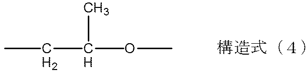
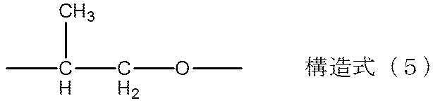
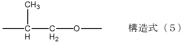
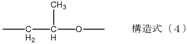
- the partial structure A is a structure in which at least one structure selected from the group consisting of structures represented by the following structural formulas (1) to (7) is sandwiched between two urethane bonds.
- R1 and R2 each independently represents a linear or branched alkylene group having 4 to 6 carbon atoms.
- FIG. 4 shows an aspect of the partial structure A.
- the structure represented by the structural formula (1) and the structure represented by the structural formula (2) are sandwiched between adjacent urethane bonds A-1 and A-2. Since the partial structure A has at least one of the structures represented by the structural formulas (1) to (7) between two urethane bonds, the urethane resin is given flexibility.
- the methyl group introduced into the side chain inhibits stacking of polymer chains.
- the crystallinity of the urethane resin in the low temperature range can be significantly reduced.
- the urethane resin having the partial structure A is rich in flexibility. Therefore, an electrophotographic member having a surface layer containing such a resin has a flexible surface layer even in a low temperature environment, hardly increases in hardness, has low stress on the toner, and does not easily cause filming.
- the chemical structures represented by the structural formulas (1) to (5) represent so-called polyether structures.
- the chemical structures represented by the structural formulas (6) and (7) represent so-called aliphatic polyester structures.
- the structures of the structural formulas (1), (2) and (3) are polyethers obtained by ring-opening copolymerization of tetrahydrofuran and 3-methyl-tetrahydrofuran.
- Structural formulas (2) and (3) are structures formed when 3-methyl-tetrahydrofuran is subjected to ring-opening copolymerization and are substantially the same.
- Structural formulas (4) and (5) are structures formed when 1,2-propylene oxide is subjected to ring-opening copolymerization and are substantially the same.
- Structural formula (6) represents a polyester structure obtained by a reaction between a diol having 4 to 6 carbon atoms and a dicarboxylic acid having 6 to 8 carbon atoms.
- Examples of the diol having 4 to 6 carbon atoms include 1,4-butanediol, 1,5-pentanediol, 3-methyl-1,5-pentanediol, and 1,6-hexanediol.
- Examples of the dicarboxylic acid having 6 to 8 carbon atoms include adipic acid, pimelic acid, and suberic acid.
- Structural formula (7) represents a structure obtained by ring-opening polymerization of ⁇ -caprolactone.
- Polyethers and polyesters having these structures are rich in flexibility and excellent in compatibility with a compound having the structure of structural formula (8) described later.
- the urethane resin having at least one structure selected from the group consisting of the structures represented by the structural formulas (1) to (7) between two adjacent urethane bonds is a polyether polyol or polyester polyol having the structure. It can be obtained by reacting with isocyanate.
- the glass transition temperature (Tg) of the urethane resin is The increase in hardness at low temperatures is greatly suppressed. Therefore, a surface layer excellent in flexibility under a low temperature environment can be obtained and preferable.
- the molar ratio of the structure of each chemical formula is within this range, a more excellent suppression effect can be obtained in terms of both toner adhesion on the surface and peeling of the surface layer. Moreover, since it is excellent also in the softness
- the surface layer containing the urethane resin having the partial structure is provided in contact with the surface of the elastic layer containing silicone rubber, the surface layer and the elastic layer are left in a high temperature and high humidity environment for a long period of time. Even in this case, good adhesion is exhibited.
- the adhesion between synthetic resins depends mainly on the interaction of polar functional groups such as hydrogen bonds and acid-base interactions in addition to chemical bonds.
- silicone rubber is very low in polarity and its surface is inert. For this reason, generally, a strong interaction due to polar functional groups cannot be expected with respect to the adhesiveness between the elastic layer containing silicone rubber and the surface layer containing polyurethane resin.
- the surface layer containing the urethane resin having the partial structure A exhibits good adhesion to the elastic layer containing silicone rubber even in a severe high temperature and high humidity environment.
- the urethane resin having the partial structure A having the above has a very low polarity as a polyurethane by introducing a methyl group into the side chain as compared with a conventional polyether polyurethane.
- the cured product of addition-curing dimethyl silicone rubber has a “spiral” molecular structure in which there are six siloxane (Si—O) bonds and one rotation, and the methyl group is oriented outward.
- the surface of the silicone rubber polymer chain is substantially covered with a hydrophobic methyl group. Therefore, hydrophobicity is present between the methyl group on the surface of the silicone rubber in the elastic layer according to the present invention and the methyl group as a side chain introduced between two adjacent urethane bonds in the urethane resin in the surface layer. The attractive force acting between the molecules is acting. As a result, it is considered that the surface layer and the elastic layer according to the present invention exhibit excellent adhesion.
- n is an integer of 1 or more and 4 or less.
- R3 is each independently R3A or R3B below, provided that at least four R3s are R3A.
- R3A is any one selected from the group consisting of the following (a) to (c).
- R3B represents a hydrogen atom or an alkyl group having 1 to 4 carbon atoms.
- R4 represents an alkylene group having 2 to 4 carbon atoms.
- m represents an integer of 2 or more and 3 or less.
- R5 represents an alkylene group having 2 to 5 carbon atoms.
- the present inventors presume the reason why the above effect is achieved by introducing the partial structure B into the urethane resin having the partial structure A as follows. That is, a cross-linked structure in which a large number of urethane groups or urea groups are formed around the structure of the structural formula (8) is formed by the reaction of the compound having the structure of the structural formula (8) and the isocyanate. As a result, interaction between urethane groups or urea groups is likely to occur, and it is considered that a reinforcing effect by physical crosslinking (pseudo-crosslinking) between urethane groups or urea groups is manifested in the urethane resin.
- the compound represented by the structural formula (8) represents a polyfunctional polyol or terminal amino compound having an amine structure in the molecule.
- n is 1 or more and 4 or less, that is, a structure having 4 or more and 7 or less hydroxyl groups or amino groups which are reactive functional groups, the reinforcing effect by the interaction of urethane groups is sufficient, and the structural formula ( By including the structures shown in 1) to (7), the filming at low temperature is excellent.
- this effect is exhibited when the number of hydroxyl groups or amino groups in the structural formula (8) is 4 or more and 7 or less. Therefore, the number of terminal functional groups in the structural formula (8) may be at least 4, and the same effect can be obtained even if the remainder is substituted with an alkyl group.
- each R3 is independently the following R3A or the following R3B, provided that at least four R3 are R3A.
- R3A is any one selected from the group consisting of the following (a) to (c).
- R3A is a hydroxyalkyl group
- the number of carbon atoms is 1 or more and 8 or less.
- R3A is an aminoalkyl group, the number of carbon atoms is 2 or more and 8 or less. Therefore, excellent deformation recovery is obtained.
- R3B is preferably a hydrogen atom or an alkyl group having 1 to 4 carbon atoms, because it is difficult to sterically hinder the interaction between urethane groups.
- Structural formula (9) represents a group having a terminal hydroxyl group having a so-called ether repeating unit.
- R3A is a group represented by the structural formula (9)
- R5 is preferably an alkylene group having 2 to 5 carbon atoms
- the ether repeat number m is preferably 2 to 3 inclusive.
- R3 is R3B, it is preferably a hydrogen atom or an alkyl group having 1 to 4 carbon atoms.
- R4 is preferably an alkylene group having 2 to 4 carbon atoms.
- the alkylene group has 2 or more and 4 or less carbon atoms, so that excellent deformation recovery properties can be obtained.
- n 1 or 2
- R3 is independently 2 or 3 carbon atoms.
- R4 is particularly preferably an alkylene group having 2 carbon atoms.
- the urethane resin containing the partial structure B derived from the compound represented by the structural formula (10) has a functional group value (pentafunctional) and a distance between the urethane groups within the most suitable range, so that the deformation recovery property particularly at high temperatures. Excellent flexibility at low temperatures.
- n is 1 or 2
- Each R6 is independently an alkylene group having 2 or 3 carbon atoms
- R7 represents an alkylene group having 2 carbon atoms.
- the structure formed by the reaction of the compound represented by the structural formula (8) and the polyisocyanate is the terminal of the structural formula (8) when R3A is the following (a) or (c). It has a structure having a urethane group.
- R3A When it is a hydroxyalkyl group having 1 to 8 carbon atoms.
- C When it is group shown by the said Structural formula (9).
- R3A is (b) an aminoalkyl group having 1 to 8 carbon atoms
- the structure has a urea group at the terminal of the structural formula (8).
- a polyether polyol having a chemical structure represented by the structural formulas (1) to (5) or a polyester polyol having a chemical structure represented by the structural formulas (6) and (7) is reacted with a polyisocyanate to produce an isocyanate.
- a base end prepolymer is obtained.
- the urethane resin according to the present invention can be obtained by reacting the isocyanate group-terminated prepolymer with the compound having the structure of the structural formula (8).
- a flexible polyether or polyester segment can be arranged around the structure of the structural formula (8) by reacting with a compound having the structure of the structural formula (8). Therefore, it is possible to suppress the so-called hard segment aggregation in which a large number of urethane groups interact with each other. Excellent deformation recovery when stored for a long period of time in a high temperature and high humidity environment. It becomes possible to do.
- the number average molecular weight of the polyether polyol and polyester polyol is particularly preferably 1000 or more and 4000 or less.
- the hard segment that is, the structural formula (8) and the group of urethane groups or urea groups formed around the hard segment are not easily aggregated, and the flexibility is excellent.
- the number average molecular weight of the polyol is 4000 or less, the amount of hydroxyl groups relative to the molecular weight is large, so that it is highly reactive with isocyanate, and the number of unreacted components decreases, so that deformation is restored when stored for a long time in a high temperature and high humidity environment. The property becomes better.
- polyethylene glycol in addition to the structure selected from the group consisting of the structures represented by structural formulas (1) to (7) between the two urethane bonds, polyethylene glycol, if necessary, to the extent that the effects of the present invention are not impaired.
- An aliphatic polyester may be contained.
- aliphatic polyester polyols obtained by a condensation reaction between a diol component such as neopentyl glycol and a triol component such as trimethylolpropane and a dicarboxylic acid such as adipic acid, glutaric acid, and sebacic acid.
- polyol components may be prepolymers that are chain-extended with an isocyanate such as 2,4-tolylene diisocyanate (TDI), 1,4 diphenylmethane diisocyanate (MDI), or isophorone diisocyanate (IPDI) as required.
- TDI 2,4-tolylene diisocyanate
- MDI 1,4 diphenylmethane diisocyanate
- IPDI isophorone diisocyanate
- Components other than the structure selected from the group consisting of the structures represented by the structural formulas (1) to (7) preferably have a content of 20% by mass or less in the polyurethane from the viewpoint of manifesting the effects of the present invention.
- the isocyanate compound to be reacted with the polyol component and the compound represented by the structural formula (8) is not particularly limited, but aliphatic polyisocyanates such as ethylene diisocyanate and 1,6-hexamethylene diisocyanate (HDI).
- aliphatic polyisocyanates such as ethylene diisocyanate and 1,6-hexamethylene diisocyanate (HDI).
- Cycloaliphatic polyisocyanates such as isocyanate, isophorone diisocyanate (IPDI), cyclohexane 1,3-diisocyanate, cyclohexane 1,4-diisocyanate, 2,4-tolylene diisocyanate, 2,6-tolylene diisocyanate (TDI), 4, Aromatic isocyanates such as 4′-diphenylmethane diisocyanate (MDI), polymeric diphenylmethane diisocyanate, xylylene diisocyanate, naphthalene diisocyanate, and copolymers thereof; Isocyanurate body, TMP adduct, biuret, it can be used the block body.
- IPDI isophorone diisocyanate
- TMP adduct cyclohexane 1,3-diisocyanate
- TDI 2,6-tolylene diisocyanate
- Aromatic isocyanates
- aromatic isocyanates such as tolylene diisocyanate, diphenylmethane diisocyanate, and polymeric diphenylmethane diisocyanate are more preferably used.
- the mixing ratio of the isocyanate component to be reacted with the polyol component and the compound represented by the structural formula (8) is such that the ratio of isocyanate groups is 1.0 to 2.0 with respect to each hydroxyl group of 1.0. preferable.
- the surface layer 4 preferably has conductivity.
- the conductivity imparting means include addition of an ionic conductive agent and conductive fine particles.
- conductive fine particles which are inexpensive and have little resistance fluctuation in the environment are preferably used, and carbon is used from the viewpoint of conductivity imparting and reinforcing properties. Black is particularly preferred.
- carbon black having a primary particle diameter of 18 nm to 50 nm and a DBP oil absorption of 50 ml / 100 g to 160 ml / 100 g has a balance of conductivity, hardness and dispersibility. Good and preferred.
- the content rate of electroconductive fine particles is 10 to 30 mass% with respect to 100 mass parts of resin components which form a surface layer.
- fine particles for controlling the roughness may be added to the surface layer 4.
- the fine particles for roughness control preferably have a volume average particle size of 3 to 20 ⁇ m.
- the amount of particles added to the surface layer is preferably 1 to 50 parts by mass with respect to 100 parts by mass of the resin solid content of the surface layer.
- fine particles for roughness control fine particles of polyurethane resin, polyester resin, polyether resin, polyamide resin, acrylic resin, and phenol resin can be used.
- the method for forming the surface layer 4 is not particularly limited, and examples thereof include spraying with paint, immersion, or roll coating.
- the dip coating method for overflowing paint from the upper end of the dip tank as described in JP-A-57-5047 is simple and excellent in production stability as a method for forming a surface layer.
- the electrophotographic member of the present invention is applicable to any of a non-contact developing device and a contact developing device using a magnetic one-component developer or a non-magnetic one-component developer, a developing device using a two-component developer, and the like. can do.
- FIG. 2 is a cross-sectional view of a process cartridge according to the present invention.
- the process cartridge 17 shown in FIG. 2 includes a conductive roller 1 (used as a developer carrying member), a developing blade 21, a developing device 22, an electrophotographic photosensitive member 18, a cleaning blade 26, a waste toner container 25, and A charging roller 24 is integrated.
- the process cartridge is configured to be detachable from the main body of the electrophotographic image forming apparatus.
- the developing device 22 includes a toner container 20, and the toner container 20 is filled with toner 20a.
- the toner 20 a in the toner container 20 is supplied to the surface of the developer carrier 1 by the toner supply roller 19, and a layer of toner 20 a having a predetermined thickness is formed on the surface of the conductive roller 1 by the developing blade 21.
- FIG. 3 is a cross-sectional view of an electrophotographic apparatus using the electrophotographic member according to the present invention as a developer carrier.
- a developing device 22 including a conductive roller 1 (used as a developer carrying member), a toner supply roller 19, a toner container 20, and a developing blade 21 is detachably mounted.
- a process cartridge 17 including a photoconductor 18, a cleaning blade 26, a waste toner container 25, and a charging roller 24 is detachably mounted. Further, the photoconductor 18, the cleaning blade 26, the waste toner container 25, and the charging roller 24 may be provided in the main body of the electrophotographic apparatus.
- the photoconductor 18 rotates in the direction of the arrow, is uniformly charged by a charging roller 24 for charging the photoconductor 18, and the surface of the photoconductor 18 is exposed by laser light 23 that is an exposure means for writing an electrostatic latent image on the photoconductor 18.
- An electrostatic latent image is formed.
- the electrostatic latent image is developed by applying the toner 20a by the developing device 22 disposed in contact with the photoconductor 18, and visualized as a toner image.
- the visualized toner image on the photoconductor 18 is transferred to a paper 34 as a recording medium by a transfer roller 29 as a transfer member.
- the paper 34 is fed into the apparatus through a paper feed roller 35 and a suction roller 36, and is transported between the photoconductor 18 and the transfer roller 29 by an endless belt-shaped transfer transport belt 32.
- the transfer / conveying belt 32 is operated by a driven roller 33, a driving roller 28, and a tension roller 31.
- a voltage is applied to the transfer roller 29 and the suction roller 36 from a bias power source 30.
- the paper 34 to which the toner image has been transferred is subjected to fixing processing by the fixing device 27, discharged outside the device, and the printing operation is completed.
- the untransferred toner remaining on the photoconductor 18 without being transferred is scraped off by a cleaning blade 26 which is a cleaning member for cleaning the surface of the photoconductor and stored in a waste toner container 25.
- the developing device 22 is a toner container 20 that contains toner 20a as a one-component developer, and a developer carrier that is located in an opening extending in the longitudinal direction in the toner container 20 and is opposed to the photoconductor 18.
- the developing device 22 develops and visualizes the electrostatic latent image on the photoreceptor 18.
- the substrate 2 was prepared by applying a primer (trade name, DY35-051; manufactured by Toray Dow Corning Co.) to a 6 mm diameter cored bar made of SUS304 and baking it.
- a primer trade name, DY35-051; manufactured by Toray Dow Corning Co.
- an elastic roller D-1 having a silicone rubber elastic layer having a diameter of 12 mm formed on the outer periphery of the base 2 was produced.
- Table 2 shows the polyether diol species used in the synthesis of the isocyanate group-terminated prepolymers B-1 to B-17, the isocyanate species, and the isocyanate group content (% by weight) of each isocyanate group-terminated prepolymer.
- the apparatus and conditions used for the measurement of the number average molecular weight (Mn) in this example are as follows. Measuring instrument: HLC-8120GPC (manufactured by Tosoh Corporation) Column: TSKgel SuperHZMM (manufactured by Tosoh Corporation) x 2 Solvent: THF Temperature: 40 ° C THF flow rate: 0.6 ml / min The measurement sample was a 0.1% by mass THF solution. Further, an RI (refractive index) detector was used as a detector for measurement.
- TSK standard polystyrenes A-1000, A-2500, A-5000, F-1, F-2, F-4, F-10, F-20, F-40, F- 80, F-128 (manufactured by Tosoh Corporation) was used to prepare a calibration curve.
- the number average molecular weight was determined from the retention time of the measurement sample obtained based on this.
- Table 4 shows the structure of the amino compound obtained.
- n represents the number of repeating amino structural units of the structural formula (8)
- m represents the number of ether repeating when R3 is the structural formula (9).
- the number of groups in the table represents the number of terminal hydroxyl groups or terminal amino groups that the amino compound has in one molecule.
- the material for the surface layer 43.9 parts by mass of amino compound C-1 and carbon black (trade name, MA230; manufactured by Mitsubishi Chemical Corporation) 108.0 with respect to 794.3 parts by mass of isocyanate group-terminated prepolymer B-1. Part by mass and 90.0 parts by mass of urethane resin fine particles (trade name, Art Pearl C-400; manufactured by Negami Kogyo Co., Ltd.) were mixed with stirring. Next, methyl ethyl ketone (hereinafter referred to as MEK) was added so that the total solid content ratio was 30% by mass, and then mixed in a sand mill. Next, the surface layer-forming coating material was prepared by adjusting the viscosity to 10 to 13 cps with MEK.
- MEK methyl ethyl ketone
- the previously created elastic roller D-1 was dipped in the surface layer forming paint to form a coating film of the paint on the surface of the elastic layer of the elastic roller D-1 and dried. Furthermore, a surface layer having a film thickness of about 15 ⁇ m was provided on the outer periphery of the elastic layer by heat treatment at a temperature of 160 ° C. to produce an electrophotographic member according to Example 1.
- the urethane resin has at least one structure selected from the group consisting of structural formulas (1) to (7) and a structure formed by reaction of the compound represented by structural formula (8) with polyisocyanate. It can be confirmed by, for example, analysis by pyrolysis GC / MS, FT-IR or NMR.
- a pyrolysis apparatus (trade name: Pyrofoil Sampler JPS-700, manufactured by Nippon Analytical Industrial Co., Ltd.) and a GC / MS apparatus (trade name: Focus GC / ISQ, Thermo Fisher Scientific) Fic Co.) was used, and the thermal decomposition temperature was 590 ° C. and helium was used as the carrier gas, and the analysis was performed.
- the resulting fragment peak is formed by the reaction of the compound represented by the structural formula (8) with the polyisocyanate together with at least one structure selected from the group consisting of the structural formulas (1) to (7). It was confirmed that the structure has
- the distance from the center to the surface of the obtained developer carrying member of this example was measured using the following apparatus.
- This measuring apparatus has an LED size comprising a conductive substrate receiver (not shown) that rotates with respect to the conductive substrate, an encoder (not shown) that detects the rotation of the conductive substrate, a reference plate 29, an LED light emitting part, and a light receiving part.
- a measuring machine (LS-7000 (trade name), manufactured by Keyence Corporation) is provided.
- the distance from the center of the developer carrier to the surface was calculated by measuring the gap amount 30 between the surface of the developer carrier and the reference plate.
- the gap amount between the surface of the developer carrying member and the reference plate is measured for a total of three points at the central portion in the longitudinal direction of the elastic layer and the position of 20 mm from both ends of the elastic layer to the central portion in the longitudinal direction. 360 points were measured at a pitch of 1 ° with respect to the circumference of the agent carrier. The measurement was performed in an environment of 23 ° C. and 55% RH using a roller that was left in an environment of a temperature of 23 ° C. and a relative humidity of 55% for 6 hours or more.
- the developer carrier measured in advance as described above was incorporated into a cyan cartridge for a laser printer (trade name, LBP7700C; manufactured by Canon Inc.). However, the contact pressure between the developer carrying member and the developing blade was adjusted to 50 gf / cm, and the setting was changed to a stricter setting for deformation. Next, the cartridge was left in a high temperature and high humidity environment (temperature 40 ° C., relative humidity 95%) for 30 days. Thereafter, the developer carrying member was removed from the cartridge and allowed to stand for 6 hours in an environment of a temperature of 23 ° C. and a relative humidity of 55%. Thereafter, the distance from the center of the developer carrier to the surface was measured in an environment of a temperature of 23 ° C.
- the measurement is performed at the same position as the measurement point before leaving in the high temperature and high humidity environment, and the change in the distance from the center to the surface of the developer carrier before and after being left in the high temperature and high humidity environment at the developing blade contact position. That is, the amount of residual deformation was determined and used as deformation recovery.
- the surface hardness of the developer carrying member was measured with a micro rubber hardness meter (trade name: MD-1capa, manufactured by Kobunshi Keiki Co., Ltd.) using a push needle having a diameter of 0.16 mm.
- the measurement uses the value after 2 seconds from the weight, the temperature is 25 ° C., the relative humidity is 50% RH environment (under L / L environment), the central part of the developer carrier after the formation of the conductive resin layer, the upper end part, The average value measured about 3 points
- Examples 2 to 39 A coating material for forming a surface layer was prepared in the same manner as in Example 1 except that the material shown in Table 5 below was used as the material for the surface layer 4. Each paint was applied to the elastic roller D-1 in the same manner as in Example 1, dried and heated to produce developer carriers according to Examples 2 to 39.
- the surface layer forming paint according to Comparative Example 1 was prepared in the same manner as the method for preparing the surface layer forming paint according to Example 1.
- This surface layer forming coating was applied to the surface of the silicone rubber elastic layer of the elastic roller D-1 in the same manner as in Example 1 and dried to form a surface layer, whereby a developer carrying member of Comparative Example 1 was prepared. .
- Example 2 A coating material for forming a surface layer was prepared in the same manner as in Example 1 except that the material shown in Table 6 below was used as the material for the surface layer 4. Then, each coating material was applied to the elastic roller D-1 in the same manner as in Example 1, dried and heated to produce developer carriers according to Comparative Examples 2 to 10.
- Examples 1 to 39 contain the urethane resin of the present invention in the surface layer, the amount of residual deformation is small and the set image is good even after being left in a high temperature and severe environment for a long time. Further, the increase in the hardness of the roller surface at a low temperature is suppressed, and the filming resistance is good.
- the urethane resins according to Examples 32 to 39 are prepared by reacting a polyol having the structure of the structural formulas (1) and (2) and / or (3) with an isocyanate to form an isocyanate group-terminated prepolymer, A curing reaction is carried out with the compound represented by the formula (8).
- the electrophotographic member provided with the surface layer containing such a urethane resin has excellent flexibility and low temperature filming at a higher level in addition to a small residual deformation amount.
- Examples 25 to 39 include a urethane resin formed by using a polyisocyanate having a number average molecular weight of 1000 or more and 4000 or less and a chain extended with a polyol having an average functional group value of 2 or more and 3 or less.
- a urethane resin formed by using a polyisocyanate having a number average molecular weight of 1000 or more and 4000 or less and a chain extended with a polyol having an average functional group value of 2 or more and 3 or less.
- Such an electrophotographic member is excellent in surface flexibility, and filming at a low temperature is suppressed at a high level.
- the electrophotographic members according to Comparative Examples 5 to 7, 9 and 10 using urethane resins containing no structure formed by the reaction of the compound represented by the structural formula (8) and polyisocyanate have residual deformation. The amount is large, and image defects are occurring. Further, in the electrophotographic member according to Comparative Example 8, a decrease in filming resistance is recognized due to an increase in surface hardness.
- Conductive roller 2 Conductive substrate 3: Elastic layer 4: Surface layer
Landscapes
- Physics & Mathematics (AREA)
- General Physics & Mathematics (AREA)
- Polyurethanes Or Polyureas (AREA)
- Dry Development In Electrophotography (AREA)
- Electrophotography Configuration And Component (AREA)
Description




構造式(6)中、
R1及びR2は各々独立に炭素数4以上6以下の直鎖、または分岐を有するアルキレン基を表す。


構造式(8)中、
nは1以上4以下の整数である。
R3は各々独立に下記R3Aまたは下記R3Bであり、 但し、少なくとも4つのR3はR3Aである。
R3Aは、下記(a)~(c)からなる群から選ばれる何れかである。
(a)炭素数1以上8以下のヒドロキシアルキル基、
(b)炭素数2以上8以下のアミノアルキル基、
(c)下記構造式(9)で示される基、
R3Bは、水素原子または炭素数1以上4以下のアルキル基を表す。
R4は炭素数2以上4以下のアルキレン基を表す。

構造式(9)中、
mは2以上3以下の整数を表す。
R5は炭素数2以上5以下のアルキレン基を表す。
基体2は、導電性ローラ1の電極および支持部材として機能するもので、アルミニウム、銅合金、ステンレス鋼の如き金属または合金;クロム、又はニッケルで鍍金処理を施した鉄;導電性を有する合成樹脂の如き導電性の材質で構成される。
弾性層3は、導電性ローラと感光体との当接部において、所定の幅のニップを形成するために必要な弾性を導電性ローラに与えるものである。
表面層4は、2つの異なる部分構造を分子内に有するウレタン樹脂を含む。以降、2つの異なる部分構造を各々、「部分構造A」および「部分構造B」という。以下、部分構造Aおよび部分構造Bについて詳述する。
部分構造Aは、下記構造式(1)~(7)で示される構造からなる群から選ばれる少なくとも一つの構造が、2つのウレタン結合によって挟まれている構造である。



構造式(6)中、R1及びR2は各々独立に炭素数4以上6以下の直鎖、または分岐を有するアルキレン基を表す。

部分構造Aにおいては、2つのウレタン結合間に、構造式(1)~(7)で示される構造の少なくとも1つを有するため、ウレタン樹脂に柔軟性を与える。
特に、2つのウレタン結合間に、構造式(2)~(5)で示される構造の少なくとも1つを有する場合には、側鎖に導入されてなるメチル基が、ポリマー鎖同士のスタッキングを阻害し、ウレタン樹脂の低温域における結晶性を著しく低下させることができる。このように、部分構造Aを有するウレタン樹脂は柔軟性に富む。そのため、かかる樹脂を含む表面層を備えた電子写真用部材は、低温環境下でも表面層が柔軟で、硬度が上昇しにくく、トナーに与えるストレスが低く、フィルミングを生じにくいものとなる。
構造式(1)、(2)、(3)の構造は、テトラヒドロフラン、3-メチル-テトラヒドロフランを開環共重合して得られるポリエーテルである。構造式(2)と(3)は3-メチル-テトラヒドロフランを開環共重合した際生ずる構造であり、実質的に同じである。また、構造式(4)と(5)は1,2-プロピレンオキシドを開環共重合した際生ずる構造であり、実質的に同じである。構造式(6)は、炭素数が4以上6以下のジオールと、炭素数6以上8以下のジカルボン酸との反応で得られるポリエステル構造を表す。
その理由は、低温域での結晶性の低減効果、および高温域での分子運動性の抑制効果がより高いためである。この場合において、「構造式(1)で示される構造のモル数」:「構造式(2)で示される構造のモル数および構造式(3)で示される構造のモル数の総和」=80:20~50:50であることが好ましい。各化学式の構造のモル比がこの範囲であると、表面のトナー固着性、また表面層剥がれの両面において、より優れた抑制効果を得られる。また低温域での柔軟性にも優れるため、耐久性も良好となる。
ここで、シリコーンゴムを含む弾性層の表面に接して、上記部分構造を有するウレタン樹脂を含む表面層を設けた場合、該表面層と該弾性層とは、高温高湿環境下に長期間放置した場合においても良好な接着性を示す。通常、合成樹脂同士の接着性は、化学結合に加えて、水素結合、酸-塩基相互作用のような、主に極性官能基の相互作用に依存する。しかし、シリコーンゴムは非常に極性が低く、その表面は不活性である。そのため、一般に、シリコーンゴムを含む弾性層とポリウレタン樹脂を含む表面層との接着性に関して、極性官能基による強い相互作用は期待できない。しかしながら、部分構造Aを有するウレタン樹脂を含む表面層は、シリコーンゴムを含む弾性層とは、苛酷な高温高湿環境下においても良好な接着性を示す。
その詳細な理由は現在解明中であるが、本発明者らは以下のように推測している。
すなわち、隣接するウレタン結合間に存在する構造式(1)で示される構造と、構造式(2)で示される構造および構造式(3)で示される構造からなる群から選ばれる少なくとも一つの構造とを有する部分構造Aを有するウレタン樹脂は、従来のポリエーテルポリウレタンと比較して、メチル基を側鎖に導入したことにより、ポリウレタンとしては非常に低極性となっている。一方、付加硬化型ジメチルシリコーンゴムの硬化物は、シロキサン(Si-O)結合が6個で1回転する「らせん状」の分子構造を有しており、かつ、メチル基が外側に配向していることが知られている。
つまり、シリコーンゴムのポリマー鎖の表面は、疎水性のメチル基で実質的に被覆されている。そのため、本発明に係る弾性層中のシリコーンゴム表面のメチル基と、表面層中のウレタン樹脂中の隣接する2つのウレタン結合の間に導入された側鎖としてのメチル基との間に疎水性の分子間に働く引力が作用している。その結果として、本発明に係る表面層と弾性層とは優れた接着性を示すものと考えられる。
通常、構造式(1)~(7)で示される構造を2つの隣接するウレタン結合間に有する部分は剛直な分子構造を有さない。そのため、部分構造Aを有するウレタン樹脂の硬度は低くなる。そのため、このようなウレタン樹脂を含む表面層を備えた電子写真用部材は、その表面に他の部材が長期に亘って当接した状態で放置されたような場合に、当該表面層に容易に回復しない変形、すなわち、圧縮永久歪み(以降、「Cセット」ともいう。なお、「Cセット」とは、コンプレッションセットの意味である)が生じることがある。
しかしながら、ウレタン樹脂中に、部分構造Aに加えて、下記構造式(8)で示される化合物とポリイソシアネートとの反応に由来する部分構造Bを更に導入することにより、低硬度でありながら苛酷な高温高湿環境下に長期間放置した場合にも良好な変形回復性を示す。

nは1以上4以下の整数である。
R3は各々独立に下記R3Aまたは下記R3Bであり、 但し、少なくとも4つのR3はR3Aである。
R3Aは、下記(a)~(c)からなる群から選ばれる何れかである。
(a)炭素数1以上8以下のヒドロキシアルキル基、
(b)炭素数2以上8以下のアミノアルキル基、
(c)下記構造式(9)で示される基、
R3Bは、水素原子または炭素数1以上4以下のアルキル基を表す。
R4は炭素数2以上4以下のアルキレン基を表す。

mは2以上3以下の整数を表す。
R5は炭素数2以上5以下のアルキレン基を表す。
すなわち、構造式(8)の構造を有する化合物とイソシアネートとの反応によって、構造式(8)の構造周辺に多数のウレタン基またはウレア基が生成した架橋構造が形成される。その結果、ウレタン基またはウレア基同士の相互作用が生じやすくなり、ウレタン基またはウレア基間の物理架橋(擬似架橋)による補強効果が、ウレタン樹脂中にて発現すると考えられる。
R3Aは、下記(a)~(c)からなる群から選ばれる何れかである。
(a)炭素数1以上8以下のヒドロキシアルキル基、
(b)炭素数2以上8以下のアミノアルキル基、
(c)下記構造式(9)で示される基、
炭素数2以上4以下のアルキレン基であると、ウレタンまたはウレア基同士が相互作用し易い距離となるため、すぐれた変形回復性が得られる。
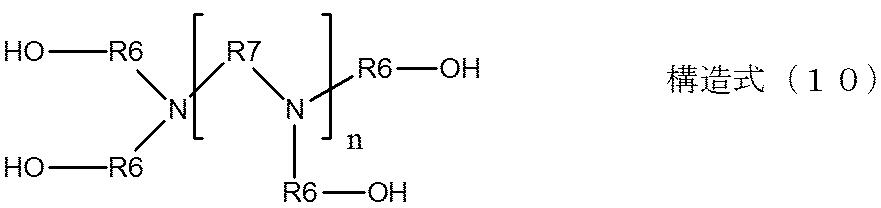
構造式(10)中、
nは1または2であり、
R6は各々独立に炭素数2または炭素数3のアルキレン基であり、
R7は炭素数2のアルキレン基を表す。
(a)炭素数1以上8以下のヒドロキシアルキル基である場合。
(c)上記構造式(9)で示される基である場合。
本発明に係るウレタン樹脂の合成方法について説明する。
まず、構造式(1)~(5)で示される化学構造を有するポリエーテルポリオール、または構造式(6)、(7)で示される化学構造を有するポリエステルポリオールとポリイソシアネートとを反応させ、イソシアネート基末端プレポリマーを得る。
構造式(1)~(7)で示される構造からなる群から選ばれる構造以外の成分は、本発明の効果発現の観点から、ポリウレタン中、20質量%以下の含有率とすることが好ましい。
図2は、本発明に係るプロセスカートリッジの断面図である。図2に示したプロセスカートリッジ17は、導電性ローラ1(現像剤担持体として使用)、現像ブレード21、及び現像装置22、電子写真感光体18、クリーニングブレード26、廃トナー収容容器25、および、帯電ローラ24が一体化されている。また、当該プロセスカートリッジは、電子写真画像形成装置の本体に着脱可能に構成されている。現像装置22は、トナー容器20を含み、トナー容器20中には、トナー20aが充填されている。トナー容器20中のトナー20aは、トナー供給ローラ19によって現像剤担持体1の表面に供給され、現像ブレード21によって、導電性ローラ1の表面に所定の厚みのトナー20aの層が形成される。
基体2として、SUS304製の直径6mmの芯金にプライマー(商品名、DY35-051;東レダウコーニング社製)を塗布、焼付けしたものを用意した。
上記で用意した基体2を金型に配置し、以下の材料を混合した付加型シリコーンゴム組成物を金型内に形成されたキャビティに注入した。
・液状シリコーンゴム材料(商品名、SE6724A/B;東レ・ダウコーニング社製)100質量部、
・カーボンブラック(商品名、トーカブラック#4300;東海カーボン社製)15質量部、
・耐熱性付与剤としてのシリカ粉体 0.2質量部、
・白金触媒 0.1質量部。
下記表1に記載した材料を混合した付加型シリコーンゴム組成物を金型内に形成されたキャビティに注入した。
続いて、金型を加熱してシリコーンゴムを温度150℃で15分間加硫して硬化させた。周面に硬化したシリコーンゴム層が形成された基体を金型から脱型した後、当該基体を、さらに温度180℃で1時間加熱して、シリコーンゴム層の硬化反応を完了させた。こうして、基体2の外周に直径12mmのシリコーンゴム弾性層が形成された弾性ローラD-1を作成した。
以下に本発明のポリウレタン表面層を得るための合成例を示す。
窒素雰囲気下、反応容器中でpure-MDI(商品名:ミリオネートMT 日本ポリウレタン工業社製)74.1質量部に対し、ポリテトラメチレングリコール系ポリオール(商品名:PTG-850 保土谷化学工業社製) 100.0質量部を反応容器内の温度を65℃に保持しつつ、徐々に滴下した。
滴下終了後、温度65℃で2時間反応させた。得られた反応混合物を室温まで冷却し、イソシアネート基含有量5.1重量%のイソシアネート基末端プレポリマーB-1を得た。

ポリオール種、配合量および反応時間を前記表1に記載の通り変更した以外はイソシアネート基末端プレポリマーB-1の合成例と同様にして、イソシアネート基末端プレポリマーB-2~B-4、B-12、B-14~B-17を得た。
窒素雰囲気下、反応容器中でトリレンジイソシアネート(TDI)(商品名:コスモネートT80;三井化学社製)43.4質量部に対し、ポリプロピレングリコール系ポリオール (商品名:サンニックスPP-1000;三洋化成工業社製)100.0gを反応容器内の温度を65℃に保持しつつ、徐々に滴下した。
滴下終了後、温度65℃で2時間反応させた。得られた反応混合物を室温まで冷却し、イソシアネート基含有量4.0重量%のイソシアネート基末端プレポリマーB-5を得た。
ポリオール種、配合量および反応時間を前記表1に記載の通り変更した以外は、イソシアネート基末端プレポリマーB-5の合成例と同様にして、イソシアネート基末端プレポリマーB-6~B-8およびB-11を得た。
窒素雰囲気下、反応容器中でポリメリックMDI(商品名:ミリオネートMR 日本ポリウレタン工業社製)26.0質量部に対し、ヘキサメチレンアジペート系ポリオール(商品名:ニッポラン136 日本ポリウレタン工業社製)を100.0g反応容器内の温度を65℃に保持しつつ、徐々に滴下した。
滴下終了後、温度65℃で2時間反応させた。得られた反応混合物を室温まで冷却し、イソシアネート基含有量4.2重量%のイソシアネート基末端プレポリマーB-9を得た。
ポリオール種、配合量および反応時間を前記表1に記載の通り変更した以外は、イソシアネート基末端プレポリマーB-5の合成例と同様にして、イソシアネート基末端プレポリマーB-10、B-13を得た。

本実施例中における数平均分子量(Mn)の測定に用いた装置、並びに条件は以下の通りである。
測定機器:HLC-8120GPC(東ソ-社製)
カラム:TSKgel SuperHZMM(東ソ-社製)×2本
溶媒:THF
温度:40℃
THFの流速:0.6ml/min
なお測定サンプルは0.1質量%のTHF溶液とした。更に検出器としてRI(屈折率)検出器を用いて測定を行った。
(アミノ化合物 C-1の合成)
撹拌装置、温度計、滴下装置および温度調整装置を取り付けた反応容器中で、攪拌しながらエチレンジアミン100.0質量部(1.67mol)、純水100質量部を40℃まで加温した。次に、反応温度を60℃以下に保持しつつ、パラホルムアルデヒド210.0質量部(7.00mol)を30分かけて徐々に滴下した。さらに1時間攪拌して反応を行い、反応混合物を得た。得られた反応混合物を減圧下加熱して水を留去し、アミノ化合物 C-1(N,N,N’,N’-テトラキス-(ヒドロキシメチル)-エチレンジアミン)を得た。
原料となるアミノ化合物種、付加材料種、配合量および反応時間を下記表3に記載の通り変更した以外は、アミノ化合物C-1の合成例と同様にして、アミノ化合物C-7、C-15を得た。

撹拌装置、温度計、滴下装置および温度調整装置を取り付けた反応容器中で、攪拌しながらエチレンジアミン100.0質量部(1.67mol)、エタノール100質量部を40℃まで加温した。次に、反応温度を60℃以下に保持しつつ、8-ブロモ-1-オクタノール1463.0質量部(7.00mol)を30分かけて徐々に滴下した。さらに1.5時間攪拌して反応を行い、反応混合物を得た。得られた反応混合物を減圧下加熱してエタノールを留去し、アミノ化合物 C-2(N,N,N’,N’-テトラキス-(ヒドロキシオクチル)-エチレンジアミン)を得た。
原料となるアミノ化合物種、付加原料種、配合量および反応時間を前記表3に記載の通り変更した以外は、アミノ化合物C-2の合成例と同様にして、アミノ化合物C-8、C-16、C-22を得た。
撹拌装置、温度計、還流管、滴下装置および温度調整装置を取り付けた反応容器中で、攪拌しながらエチレンジアミン100.0質量部(1.67mol)、純水100質量部を40℃まで加温した。次に、反応温度を40℃以下に保持しつつ、プロピレンオキシド812.0質量部(14.0mol)を30分かけて徐々に滴下した。さらに2時間攪拌して反応を行い、反応混合物を得た。得られた反応混合物を減圧下加熱して水を留去し、アミノ化合物 C-3 223gを得た。
原料となるアミノ化合物種、付加材料種、配合量および反応時間を前記表3に記載の通り変更した以外は、アミノ化合物C-3の合成例と同様にして、アミノ化合物C-4~6、C-9~14、C-24を得た。
撹拌装置、温度計、還流管、滴下装置および温度調整装置を取り付けた反応容器中で、攪拌しながらエチレンジアミン100.0質量部(1.67mol)、純水100質量部を40℃まで加温した。次に、反応温度を40℃以下に保持しつつ、エチレンイミン301.0質量部(7.00mol)を30分かけて徐々に滴下した。さらに1時間攪拌して反応を行い、反応混合物を得た。得られた反応混合物を減圧下加熱して水を留去し、アミノ化合物 C-17(N,N,N’,N’-テトラキス-(アミノメチル)-エチレンジアミン)を得た。
原料となるアミノ化合物種、付加材料種、配合量および反応時間を前記表3に記載の通り変更した以外は、アミノ化合物C-17の合成例と同様にして、アミノ化合物C-18、C-20を得た。
撹拌装置、温度計、還流管、滴下装置および温度調整装置を取り付けた反応容器中で、攪拌しながらブチレンジアミン100.0質量部(1.14mol)、エタノール100質量部を40℃まで加温した。次に、反応温度を40℃以下に保持しつつ、8-ブロモ-1-アミノオクタン992.7質量部(4.77mol)を30分かけて徐々に滴下した。さらに1.5時間攪拌して反応を行い、反応混合物を得た。得られた反応混合物を減圧下加熱してエタノールを留去し、アミノ化合物 C-19 を得た。
原料となるアミノ化合物種、付加材料種、配合量および反応時間を前記表3に記載の通り変更した以外は、アミノ化合物C-19の合成例と同様にして、アミノ化合物C-21、C-23を得た。


以下に、本願発明の電子写真用部材の製造法について説明する。
次に、総固形分比が30質量%となるようにメチルエチルケトン(以下MEK)を加えた後、サンドミルにて混合した。ついで、更に、MEKで粘度10~13cpsに調整して表面層形成用塗料を調製した。
先に作成した弾性ローラD-1を、表面層形成用塗料に浸漬して、弾性ローラD-1の弾性層の表面に当該塗料の塗膜を形成し、乾燥させた。さらに温度160℃にて1時間加熱処理することで弾性層外周に膜厚約15μmの表面層を設け、実施例1に係る電子写真用部材を作成した。
まず、得られた本実施例の現像剤担持体の中心から表面までの距離を、以下の装置を用いて測定した。本測定装置は、導電性基体を基準に回転する導電性基体受け(不図示)、導電性基体の回転を検知するエンコーダー(不図示)、基準板29、LED発光部および受光部からなるLED寸法測定機(LS-7000(商品名)、キーエンス社製)を備えている。
現像剤担持体の表面と基準板との隙間量30を測定することにより、現像剤担持体の中心から表面までの距離を算出した。なお、現像剤担持体の表面と基準板との隙間量の測定は、弾性層長手方向中央部、および弾性層の両端部から長手方向中央部側に20mmの位置の合計3点に関して行い、現像剤担持体1周に対して1°ピッチで360点の測定を行った。測定は、温度23℃、相対湿度55%の環境中に6時間以上放置したローラを用いて、23℃、55%RHの環境で行った。
次に該カートリッジを、高温高湿環境(温度40℃、相対湿度95%)に30日間放置した。その後、現像剤担持体を該カートリッジから取り外し、温度23℃、相対湿度55%の環境下で6時間放置した。その後、現像剤担持体の中心から表面までの距離を、温度23℃、相対湿度55%RHの環境下で測定した。
測定は、上記高温高湿環境に放置前の測定箇所と同じ位置について行い、現像ブレード当接位置における高温高湿環境下での放置前後での現像剤担持体の中心から表面までの距離の変化、すなわち残留変形量を求め、変形回復性とした。
キヤノン製レーザプリンター(商品名:LBP7700C、キヤノン製)のシアンカートリッジに、上記残留変形量の測定を終えた現像剤担持体を組み込み、画像出力試験用カートリッジを作製した。
この画像出力試験用カートリッジを、上記レーザプリンターに装填し、ハーフトーン画像の出力を行った。得られたハーフトーン画像について、以下の基準に従って評価した。なお、残留変形量の測定からハーフトーン画像の出力までは1時間とした。
A:均一な画像が得られた
B:現像剤担持体の変形に起因する濃度ムラが極めて軽微に見られる
C:画像の端部または全体に現像剤担持体の変形に起因する濃度ムラが見られる
現像剤担持体の表面硬度を、マイクロゴム硬度計(商品名:MD-1capa、高分子計器社製)にて、直径0.16mm押針を用い測定した。測定は、加重から2秒後の値を用い、気温25℃、相対湿度50%RH環境下(L/L環境下)、導電性樹脂層形成後の現像剤担持体の中央部、上端部、下端部3点について測定した平均値を用いた。
フィルミングの評価は、図3のような構成を有するレーザプリンター(商品名、LBP7700C;キヤノン社製)に本実施例の現像剤担持体(新品)を現像ローラとして装填し、評価を行った。気温15℃、相対湿度10%RH環境下、ブラックトナーを用い、印字率1%にて連続印刷を行った。1000枚ごとに画像の確認を行い、フィルミングによる印字部、非印字部の濃度差が目視で確認された時点での枚数をフィルミング発生枚数とした。
表面層4の材料として、下記表5の材料を用いた以外は実施例1と同様に表面層形成用塗料を作成した。そして、各塗料を弾性ローラD-1に対して、実施例1と同様にして塗布、乾燥および加熱を行って実施例2~39に係る現像剤担持体を作成した。

表面層4の材料として、イソシアネート基末端プレポリマーB-14 803.5質量部に対し、アミノ化合物C-1 37.5質量部、カーボンブラック(商品名、MA230;三菱化学社製)108.0質量部、及びウレタン樹脂微粒子(商品名、アートパールC-400;根上工業社製)90.0質量部、を撹拌混合した。
表面層4の材料として、下記表6の材料を用いた以外は実施例1と同様に表面層形成用塗料を作成した。そして、各塗料を弾性ローラD-1に対して、実施例1と同様にして塗布、乾燥および加熱を行って比較例2~10に係る現像剤担持体を作成した。


2:導電性基体
3:弾性層
4:表面層
Claims (7)
- 基体、弾性層およびウレタン樹脂を含む表面層を有する電子写真用部材であって、
該ウレタン樹脂は、
隣接する2つのウレタン結合の間に下記構造式(1)~(7)からなる群から選択される少なくとも1つの構造を有する部分構造Aを有し、かつ、
下記構造式(8)で示される化合物とポリイソシアネートとの反応に由来する部分構造Bを更に有することを特徴とする電子写真用部材:




構造式(6)中、R1及びR2は各々独立に炭素数4以上6以下の直鎖、または分岐を有するアルキレン基を表す。


構造式(8)中、
nは1以上4以下の整数である。
R3は各々独立に下記R3Aまたは下記R3Bであり、 但し、少なくとも4つのR3はR3Aである。
R3Aは、下記(a)~(c)からなる群から選ばれる何れかである。
(a)炭素数1以上8以下のヒドロキシアルキル基、
(b)炭素数2以上8以下のアミノアルキル基、
(c)下記構造式(9)で示される基、
R3Bは、水素原子または炭素数1以上4以下のアルキル基を表す。
R4は炭素数2以上4以下のアルキレン基を表す。

構造式(9)中、mは2以上3以下の整数を表す。R5は炭素数2以上5以下のアルキレン基を表す。 - 前記ウレタン樹脂は、隣接する2つのウレタン結合の間に、
前記構造式(1)で示される構造と、
前記構造式(2)で示される構造および前記構造式(3)で示される構造からなる群から選ばれる少なくとも一方の構造と、を有する部分構造を有する請求項1に記載の電子写真用部材。 - 前記構造式(8)で示される化合物が、下記構造式(10)で示される化合物である請求項1または2に記載の電子写真用部材。

構造式(10)中、
nは1または2である。
R6は各々独立に炭素数2または炭素数3のアルキレン基であり、
R7は炭素数2のアルキレン基を表す。 - 前記ポリイソシアネートが、数平均分子量が1000以上4000以下であり、平均官能基価が2以上3以下のポリオールによって鎖延長されたポリイソシアネートである請求項1~3のいずれか一項に記載の電子写真用部材。
- 前記弾性層がシリコーンゴムの硬化物を含む請求項1~4のいずれか一項に記載の電子写真用部材。
- 現像剤担持体が装着されてなり、電子写真装置の本体に着脱可能に構成されているプロセスカートリッジであって、該現像剤担持体が、請求項1~5のいずれか一項に記載の電子写真用部材であることを特徴とするプロセスカートリッジ。
- 電子写真感光体と、該電子写真感光体に対向して配置され、該電子写真感光体に対してトナーを供給する現像剤担持体と、を備えている電子写真装置において、
該現像剤担持体が、請求項1~5のいずれか一項に記載の電子写真用部材であることを特徴とする電子写真装置。
Priority Applications (5)
| Application Number | Priority Date | Filing Date | Title |
|---|---|---|---|
| CN201380034308.1A CN104412171B (zh) | 2012-06-27 | 2013-06-19 | 电子照相用构件、处理盒和电子照相设备 |
| EP13810864.2A EP2869131B1 (en) | 2012-06-27 | 2013-06-19 | Electrophotographic member, process cartridge and electrophotographic apparatus |
| RU2015102146/04A RU2583379C1 (ru) | 2012-06-27 | 2013-06-19 | Электрофотографический элемент, технологический картридж и электрофотографическое устройство |
| KR1020157001375A KR101605294B1 (ko) | 2012-06-27 | 2013-06-19 | 전자 사진용 부재, 프로세스 카트리지 및 전자 사진 장치 |
| US14/101,299 US8846287B2 (en) | 2012-06-27 | 2013-12-09 | Electrophotographic member, process cartridge and electrophotographic apparatus |
Applications Claiming Priority (4)
| Application Number | Priority Date | Filing Date | Title |
|---|---|---|---|
| JP2012-144348 | 2012-06-27 | ||
| JP2012144348 | 2012-06-27 | ||
| JP2013126827A JP5631447B2 (ja) | 2012-06-27 | 2013-06-17 | 電子写真用部材、プロセスカートリッジおよび電子写真装置 |
| JP2013-126827 | 2013-06-17 |
Related Child Applications (1)
| Application Number | Title | Priority Date | Filing Date |
|---|---|---|---|
| US14/101,299 Continuation US8846287B2 (en) | 2012-06-27 | 2013-12-09 | Electrophotographic member, process cartridge and electrophotographic apparatus |
Publications (1)
| Publication Number | Publication Date |
|---|---|
| WO2014002429A1 true WO2014002429A1 (ja) | 2014-01-03 |
Family
ID=49782628
Family Applications (1)
| Application Number | Title | Priority Date | Filing Date |
|---|---|---|---|
| PCT/JP2013/003806 Ceased WO2014002429A1 (ja) | 2012-06-27 | 2013-06-19 | 電子写真用部材、プロセスカートリッジおよび電子写真装置 |
Country Status (7)
| Country | Link |
|---|---|
| US (1) | US8846287B2 (ja) |
| EP (1) | EP2869131B1 (ja) |
| JP (1) | JP5631447B2 (ja) |
| KR (1) | KR101605294B1 (ja) |
| CN (1) | CN104412171B (ja) |
| RU (1) | RU2583379C1 (ja) |
| WO (1) | WO2014002429A1 (ja) |
Cited By (1)
| Publication number | Priority date | Publication date | Assignee | Title |
|---|---|---|---|---|
| CN105652621A (zh) * | 2014-11-28 | 2016-06-08 | 佳能株式会社 | 电子照相用导电性构件、处理盒和电子照相图像形成设备 |
Families Citing this family (45)
| Publication number | Priority date | Publication date | Assignee | Title |
|---|---|---|---|---|
| JP6104068B2 (ja) * | 2012-06-27 | 2017-03-29 | キヤノン株式会社 | 現像部材、プロセスカートリッジおよび電子写真装置 |
| JP6320014B2 (ja) | 2012-12-13 | 2018-05-09 | キヤノン株式会社 | 電子写真用部材、プロセスカートリッジ及び電子写真装置 |
| US9442416B2 (en) * | 2013-12-26 | 2016-09-13 | Canon Kabushiki Kaisha | Image-forming apparatus, image-forming method, developing apparatus, and developing method |
| JP6231875B2 (ja) * | 2013-12-26 | 2017-11-15 | キヤノン株式会社 | 現像装置、現像方法、画像形成装置、および画像形成方法 |
| JP6234219B2 (ja) * | 2013-12-26 | 2017-11-22 | キヤノン株式会社 | 現像装置、現像方法、画像形成装置および画像形成方法 |
| JP6486188B2 (ja) | 2014-05-16 | 2019-03-20 | キヤノン株式会社 | 電子写真用部材、プロセスカートリッジ及び電子写真装置 |
| JP6415421B2 (ja) | 2014-12-26 | 2018-10-31 | キヤノン株式会社 | 電子写真用部材、プロセスカートリッジおよび電子写真装置 |
| US9482986B2 (en) | 2015-02-27 | 2016-11-01 | Canon Kabushiki Kaisha | Member for electrophotography, process cartridge, and electrophotographic image forming apparatus |
| JP6512971B2 (ja) | 2015-07-09 | 2019-05-15 | キヤノン株式会社 | 電子写真用部材、現像装置及び画像形成装置 |
| US10197930B2 (en) | 2015-08-31 | 2019-02-05 | Canon Kabushiki Kaisha | Electrophotographic member, process cartridge, and electrophotographic apparatus |
| US10082741B2 (en) | 2015-10-06 | 2018-09-25 | Canon Kabushiki Kaisha | Member for electrophotography, developing apparatus, and electrophotographic apparatus |
| JP6806579B2 (ja) | 2016-02-05 | 2021-01-06 | キヤノン株式会社 | 電子写真用部材、その製造方法、プロセスカートリッジおよび電子写真装置 |
| JP6815889B2 (ja) | 2016-02-26 | 2021-01-20 | キヤノン株式会社 | 現像ローラ、プロセスカートリッジおよび電子写真画像形成装置 |
| US10331054B2 (en) | 2016-05-11 | 2019-06-25 | Canon Kabushiki Kaisha | Electrophotographic member, process cartridge and electrophotographic image forming apparatus |
| JP6862276B2 (ja) | 2016-07-08 | 2021-04-21 | キヤノン株式会社 | 電子写真用部材、プロセスカートリッジおよび電子写真装置 |
| JP6891065B2 (ja) | 2016-07-29 | 2021-06-18 | キヤノン株式会社 | 現像装置、電子写真プロセスカートリッジ及び電子写真画像形成装置 |
| JP2018022074A (ja) | 2016-08-04 | 2018-02-08 | キヤノン株式会社 | 電子写真用部材、プロセスカートリッジ及び電子写真装置 |
| US10310447B2 (en) | 2017-07-12 | 2019-06-04 | Canon Kabushiki Kaisha | Electrophotographic member, process cartridge, and electrophotographic image forming apparatus |
| JP6463534B1 (ja) | 2017-09-11 | 2019-02-06 | キヤノン株式会社 | 現像剤担持体、プロセスカートリッジおよび電子写真装置 |
| WO2019050013A1 (ja) | 2017-09-11 | 2019-03-14 | キヤノン株式会社 | 現像剤担持体、プロセスカートリッジおよび電子写真装置 |
| JP7166854B2 (ja) | 2017-09-27 | 2022-11-08 | キヤノン株式会社 | 電子写真用部材、プロセスカートリッジ及び電子写真装置 |
| JP7057154B2 (ja) | 2018-02-26 | 2022-04-19 | キヤノン株式会社 | 現像部材、電子写真プロセスカートリッジおよび電子写真画像形成装置 |
| US11150599B2 (en) | 2018-03-16 | 2021-10-19 | Hewlett-Packard Development Company, L.P. | Air bearings |
| US10884352B2 (en) | 2018-03-30 | 2021-01-05 | Canon Kabushiki Kaisha | Electrophotographic member, process cartridge and electrophotographic apparatus |
| CN111989622B (zh) | 2018-04-18 | 2022-11-11 | 佳能株式会社 | 显影构件、处理盒和电子照相设备 |
| WO2019203238A1 (ja) | 2018-04-18 | 2019-10-24 | キヤノン株式会社 | 導電性部材及びその製造方法、プロセスカートリッジ並びに電子写真画像形成装置 |
| US10935903B2 (en) | 2018-04-19 | 2021-03-02 | Canon Kabushiki Kaisha | Developing roller, process cartridge and image forming apparatus |
| US10969709B2 (en) | 2018-04-20 | 2021-04-06 | Canon Kabushiki Kaisha | Member for electrophotography, process cartridge and electrophotographic apparatus |
| US10539891B1 (en) | 2018-06-28 | 2020-01-21 | Canon Kabushiki Kaisha | Electrophotographic member, process cartridge and electrophotographic image forming apparatus |
| US11169464B2 (en) | 2018-07-30 | 2021-11-09 | Canon Kabushiki Kaisha | Electrophotographic member, process cartridge, and electrophotographic image-forming apparatus |
| JP7158943B2 (ja) | 2018-07-31 | 2022-10-24 | キヤノン株式会社 | 電子写真用部材、電子写真プロセスカートリッジおよび電子写真画像形成装置 |
| JP7277301B2 (ja) | 2018-07-31 | 2023-05-18 | キヤノン株式会社 | 電子写真用部材、プロセスカートリッジおよび電子写真画像形成装置 |
| JP7199881B2 (ja) | 2018-08-31 | 2023-01-06 | キヤノン株式会社 | 現像ローラ、電子写真プロセスカートリッジおよび電子写真用画像形成装置 |
| JP7171385B2 (ja) * | 2018-11-22 | 2022-11-15 | キヤノン株式会社 | 現像剤担持体、プロセスカートリッジおよび電子写真装置 |
| US10732538B2 (en) | 2018-11-26 | 2020-08-04 | Canon Kabushiki Kaisha | Developing member, process cartridge, and electrophotographic image forming apparatus |
| US10705449B2 (en) | 2018-11-30 | 2020-07-07 | Canon Kabushiki Kaisha | Developing member, electrophotographic process cartridge, and electrophotographic image forming apparatus |
| EP3936942A4 (en) | 2019-03-08 | 2022-12-28 | Canon Kabushiki Kaisha | DEVELOPER SUPPORTING BODY, PROCESS CARTRIDGE AND ELECTROPHOTOGRAPHIC IMAGE FORMING DEVICE |
| US12147170B2 (en) | 2019-03-11 | 2024-11-19 | Canon Kabushiki Kaisha | Image forming apparatus having toner charging |
| US10942471B2 (en) | 2019-03-29 | 2021-03-09 | Canon Kabushiki Kaisha | Electrophotographic member having a surface layer with a cross-linked urethane resin-containing matrix, process cartridge, and apparatus |
| CN114556231B (zh) | 2019-10-18 | 2023-06-27 | 佳能株式会社 | 导电性构件、其制造方法、处理盒以及电子照相图像形成设备 |
| CN114556230B (zh) | 2019-10-18 | 2024-03-08 | 佳能株式会社 | 电子照相用导电性构件、处理盒和电子照相图像形成装置 |
| WO2021075441A1 (ja) | 2019-10-18 | 2021-04-22 | キヤノン株式会社 | 導電性部材、プロセスカートリッジ及び電子写真画像形成装置 |
| WO2021079917A1 (ja) | 2019-10-23 | 2021-04-29 | キヤノン株式会社 | 現像装置、電子写真プロセスカートリッジ、及び電子写真画像形成装置 |
| JP7621773B2 (ja) | 2019-11-22 | 2025-01-27 | キヤノン株式会社 | 電子写真用部材、プロセスカートリッジおよび電子写真画像形成装置 |
| US12235606B2 (en) | 2020-09-28 | 2025-02-25 | Canon Kabushiki Kaisha | Process cartridge |
Citations (9)
| Publication number | Priority date | Publication date | Assignee | Title |
|---|---|---|---|---|
| JPS575047A (en) | 1980-06-13 | 1982-01-11 | Ricoh Co Ltd | Coating method by dipping |
| JPH042755B2 (ja) | 1983-02-22 | 1992-01-20 | ||
| JP3572905B2 (ja) | 1997-11-11 | 2004-10-06 | 鐘淵化学工業株式会社 | 現像ローラ |
| JP2007133113A (ja) * | 2005-11-10 | 2007-05-31 | Canon Inc | 画像形成方法 |
| JP2008139482A (ja) * | 2006-11-30 | 2008-06-19 | Canon Inc | 現像ローラ、現像ローラの製造方法、プロセスカートリッジ及び電子写真装置 |
| JP2008164915A (ja) * | 2006-12-28 | 2008-07-17 | Canon Inc | 画像形成方法 |
| JP2009109861A (ja) * | 2007-10-31 | 2009-05-21 | Canon Inc | 現像ローラ、現像ローラの製造方法、プロセスカートリッジおよび電子写真装置 |
| JP2010107968A (ja) * | 2008-09-30 | 2010-05-13 | Canon Inc | 現像ローラとその製造方法、プロセスカートリッジ、電子写真装置 |
| JP4812115B2 (ja) | 2006-07-05 | 2011-11-09 | 東海ゴム工業株式会社 | 現像ロール |
Family Cites Families (12)
| Publication number | Priority date | Publication date | Assignee | Title |
|---|---|---|---|---|
| US4762941A (en) * | 1986-12-22 | 1988-08-09 | Eastman Kodak Company | Polyurethane elastomers comprising a charge control agent and shaped elements therefrom |
| US5571457A (en) * | 1994-08-31 | 1996-11-05 | Eastman Kodak Company | Biasable transfer compositions and members having extended electrical life |
| JP3527910B2 (ja) * | 1998-08-31 | 2004-05-17 | グンゼ株式会社 | 帯電ローラ式電子写真複写装置 |
| US6352771B1 (en) * | 1999-02-24 | 2002-03-05 | Mearthane Products Corporation | Conductive urethane roller |
| JP4194533B2 (ja) | 2004-06-17 | 2008-12-10 | キヤノン株式会社 | 現像ローラ及びそれを用いた画像形成装置 |
| JP4042755B2 (ja) | 2005-03-10 | 2008-02-06 | 東海ゴム工業株式会社 | 現像ロール |
| JP5043395B2 (ja) * | 2005-11-10 | 2012-10-10 | キヤノン株式会社 | 現像ローラ及びその製造方法、現像装置及び画像形成装置 |
| US7727134B2 (en) * | 2005-11-10 | 2010-06-01 | Canon Kabushiki Tokyo | Developing roller, process for its production, developing assembly and image forming apparatus |
| US8029965B2 (en) * | 2007-03-08 | 2011-10-04 | Konica Minolta Business Technologies, Inc. | Developing roller and image forming method employing the same |
| JP4372213B2 (ja) * | 2007-03-28 | 2009-11-25 | キヤノン株式会社 | 電子写真感光体、プロセスカートリッジおよび電子写真装置 |
| JP4328831B1 (ja) * | 2008-02-19 | 2009-09-09 | キヤノン株式会社 | 現像装置、電子写真画像形成装置 |
| EP2287675B1 (en) * | 2008-05-30 | 2014-10-01 | Canon Kabushiki Kaisha | Development roller, method for manufacturing thereof, process cartridge, and electrophotographic image forming device |
-
2013
- 2013-06-17 JP JP2013126827A patent/JP5631447B2/ja active Active
- 2013-06-19 EP EP13810864.2A patent/EP2869131B1/en active Active
- 2013-06-19 CN CN201380034308.1A patent/CN104412171B/zh active Active
- 2013-06-19 RU RU2015102146/04A patent/RU2583379C1/ru active
- 2013-06-19 WO PCT/JP2013/003806 patent/WO2014002429A1/ja not_active Ceased
- 2013-06-19 KR KR1020157001375A patent/KR101605294B1/ko active Active
- 2013-12-09 US US14/101,299 patent/US8846287B2/en active Active
Patent Citations (9)
| Publication number | Priority date | Publication date | Assignee | Title |
|---|---|---|---|---|
| JPS575047A (en) | 1980-06-13 | 1982-01-11 | Ricoh Co Ltd | Coating method by dipping |
| JPH042755B2 (ja) | 1983-02-22 | 1992-01-20 | ||
| JP3572905B2 (ja) | 1997-11-11 | 2004-10-06 | 鐘淵化学工業株式会社 | 現像ローラ |
| JP2007133113A (ja) * | 2005-11-10 | 2007-05-31 | Canon Inc | 画像形成方法 |
| JP4812115B2 (ja) | 2006-07-05 | 2011-11-09 | 東海ゴム工業株式会社 | 現像ロール |
| JP2008139482A (ja) * | 2006-11-30 | 2008-06-19 | Canon Inc | 現像ローラ、現像ローラの製造方法、プロセスカートリッジ及び電子写真装置 |
| JP2008164915A (ja) * | 2006-12-28 | 2008-07-17 | Canon Inc | 画像形成方法 |
| JP2009109861A (ja) * | 2007-10-31 | 2009-05-21 | Canon Inc | 現像ローラ、現像ローラの製造方法、プロセスカートリッジおよび電子写真装置 |
| JP2010107968A (ja) * | 2008-09-30 | 2010-05-13 | Canon Inc | 現像ローラとその製造方法、プロセスカートリッジ、電子写真装置 |
Non-Patent Citations (1)
| Title |
|---|
| See also references of EP2869131A4 |
Cited By (3)
| Publication number | Priority date | Publication date | Assignee | Title |
|---|---|---|---|---|
| CN105652621A (zh) * | 2014-11-28 | 2016-06-08 | 佳能株式会社 | 电子照相用导电性构件、处理盒和电子照相图像形成设备 |
| US9897931B2 (en) | 2014-11-28 | 2018-02-20 | Canon Kabushiki Kaisha | Electroconductive member for electrophotography, process cartridge, and electrophotographic image-forming apparatus |
| CN105652621B (zh) * | 2014-11-28 | 2018-04-03 | 佳能株式会社 | 电子照相用导电性构件、处理盒和电子照相图像形成设备 |
Also Published As
| Publication number | Publication date |
|---|---|
| CN104412171A (zh) | 2015-03-11 |
| JP2014029496A (ja) | 2014-02-13 |
| EP2869131A4 (en) | 2015-12-30 |
| JP5631447B2 (ja) | 2014-11-26 |
| RU2583379C1 (ru) | 2016-05-10 |
| US20140093278A1 (en) | 2014-04-03 |
| EP2869131A1 (en) | 2015-05-06 |
| US8846287B2 (en) | 2014-09-30 |
| KR101605294B1 (ko) | 2016-03-21 |
| KR20150024414A (ko) | 2015-03-06 |
| CN104412171B (zh) | 2018-08-31 |
| EP2869131B1 (en) | 2016-07-20 |
Similar Documents
| Publication | Publication Date | Title |
|---|---|---|
| JP5631447B2 (ja) | 電子写真用部材、プロセスカートリッジおよび電子写真装置 | |
| JP6104068B2 (ja) | 現像部材、プロセスカートリッジおよび電子写真装置 | |
| JP5600719B2 (ja) | 現像部材、プロセスカートリッジおよび電子写真装置 | |
| JP5079134B2 (ja) | 現像ローラ、プロセスカートリッジおよび電子写真装置 | |
| JP4360447B1 (ja) | 現像ローラ及びその製造方法、プロセスカートリッジ、電子写真画像形成装置 | |
| JP5754930B2 (ja) | トナー担持体、プロセスカ−トリッジ及び電子写真装置 | |
| JP5734084B2 (ja) | 現像ローラ、電子写真プロセスカートリッジ、及び電子写真画像形成装置 | |
| JP2008107819A (ja) | 現像ローラー、電子写真装置用プロセスカートリッジ、電子写真画像形成装置 | |
| JP2007163860A (ja) | 現像ローラ、その製造方法、プロセスカートリッジ及び電子写真装置 |
Legal Events
| Date | Code | Title | Description |
|---|---|---|---|
| 121 | Ep: the epo has been informed by wipo that ep was designated in this application |
Ref document number: 13810864 Country of ref document: EP Kind code of ref document: A1 |
|
| REEP | Request for entry into the european phase |
Ref document number: 2013810864 Country of ref document: EP |
|
| WWE | Wipo information: entry into national phase |
Ref document number: 2013810864 Country of ref document: EP |
|
| NENP | Non-entry into the national phase |
Ref country code: DE |
|
| ENP | Entry into the national phase |
Ref document number: 20157001375 Country of ref document: KR Kind code of ref document: A |
|
| ENP | Entry into the national phase |
Ref document number: 2015102146 Country of ref document: RU Kind code of ref document: A |