WO2014002600A1 - 角型電池及び角型電池の製造方法 - Google Patents
角型電池及び角型電池の製造方法 Download PDFInfo
- Publication number
- WO2014002600A1 WO2014002600A1 PCT/JP2013/062129 JP2013062129W WO2014002600A1 WO 2014002600 A1 WO2014002600 A1 WO 2014002600A1 JP 2013062129 W JP2013062129 W JP 2013062129W WO 2014002600 A1 WO2014002600 A1 WO 2014002600A1
- Authority
- WO
- WIPO (PCT)
- Prior art keywords
- opening
- lid
- pair
- short side
- portions
- Prior art date
- Legal status (The legal status is an assumption and is not a legal conclusion. Google has not performed a legal analysis and makes no representation as to the accuracy of the status listed.)
- Ceased
Links
Images


Classifications
-
- H—ELECTRICITY
- H01—ELECTRIC ELEMENTS
- H01M—PROCESSES OR MEANS, e.g. BATTERIES, FOR THE DIRECT CONVERSION OF CHEMICAL ENERGY INTO ELECTRICAL ENERGY
- H01M50/00—Constructional details or processes of manufacture of the non-active parts of electrochemical cells other than fuel cells, e.g. hybrid cells
- H01M50/10—Primary casings; Jackets or wrappings
- H01M50/147—Lids or covers
- H01M50/166—Lids or covers characterised by the methods of assembling casings with lids
- H01M50/169—Lids or covers characterised by the methods of assembling casings with lids by welding, brazing or soldering
-
- B—PERFORMING OPERATIONS; TRANSPORTING
- B23—MACHINE TOOLS; METAL-WORKING NOT OTHERWISE PROVIDED FOR
- B23K—SOLDERING OR UNSOLDERING; WELDING; CLADDING OR PLATING BY SOLDERING OR WELDING; CUTTING BY APPLYING HEAT LOCALLY, e.g. FLAME CUTTING; WORKING BY LASER BEAM
- B23K26/00—Working by laser beam, e.g. welding, cutting or boring
- B23K26/20—Bonding
- B23K26/206—Laser sealing
-
- B—PERFORMING OPERATIONS; TRANSPORTING
- B23—MACHINE TOOLS; METAL-WORKING NOT OTHERWISE PROVIDED FOR
- B23K—SOLDERING OR UNSOLDERING; WELDING; CLADDING OR PLATING BY SOLDERING OR WELDING; CUTTING BY APPLYING HEAT LOCALLY, e.g. FLAME CUTTING; WORKING BY LASER BEAM
- B23K15/00—Electron-beam welding or cutting
- B23K15/0006—Electron-beam welding or cutting specially adapted for particular articles or work
-
- B—PERFORMING OPERATIONS; TRANSPORTING
- B23—MACHINE TOOLS; METAL-WORKING NOT OTHERWISE PROVIDED FOR
- B23K—SOLDERING OR UNSOLDERING; WELDING; CLADDING OR PLATING BY SOLDERING OR WELDING; CUTTING BY APPLYING HEAT LOCALLY, e.g. FLAME CUTTING; WORKING BY LASER BEAM
- B23K15/00—Electron-beam welding or cutting
- B23K15/0046—Welding
-
- B—PERFORMING OPERATIONS; TRANSPORTING
- B23—MACHINE TOOLS; METAL-WORKING NOT OTHERWISE PROVIDED FOR
- B23K—SOLDERING OR UNSOLDERING; WELDING; CLADDING OR PLATING BY SOLDERING OR WELDING; CUTTING BY APPLYING HEAT LOCALLY, e.g. FLAME CUTTING; WORKING BY LASER BEAM
- B23K26/00—Working by laser beam, e.g. welding, cutting or boring
- B23K26/20—Bonding
- B23K26/21—Bonding by welding
- B23K26/24—Seam welding
- B23K26/26—Seam welding of rectilinear seams
-
- B—PERFORMING OPERATIONS; TRANSPORTING
- B23—MACHINE TOOLS; METAL-WORKING NOT OTHERWISE PROVIDED FOR
- B23K—SOLDERING OR UNSOLDERING; WELDING; CLADDING OR PLATING BY SOLDERING OR WELDING; CUTTING BY APPLYING HEAT LOCALLY, e.g. FLAME CUTTING; WORKING BY LASER BEAM
- B23K26/00—Working by laser beam, e.g. welding, cutting or boring
- B23K26/20—Bonding
- B23K26/21—Bonding by welding
- B23K26/24—Seam welding
- B23K26/28—Seam welding of curved planar seams
-
- B—PERFORMING OPERATIONS; TRANSPORTING
- B23—MACHINE TOOLS; METAL-WORKING NOT OTHERWISE PROVIDED FOR
- B23K—SOLDERING OR UNSOLDERING; WELDING; CLADDING OR PLATING BY SOLDERING OR WELDING; CUTTING BY APPLYING HEAT LOCALLY, e.g. FLAME CUTTING; WORKING BY LASER BEAM
- B23K33/00—Specially-profiled edge portions of workpieces for making soldering or welding connections; Filling the seams formed thereby
-
- H—ELECTRICITY
- H01—ELECTRIC ELEMENTS
- H01M—PROCESSES OR MEANS, e.g. BATTERIES, FOR THE DIRECT CONVERSION OF CHEMICAL ENERGY INTO ELECTRICAL ENERGY
- H01M50/00—Constructional details or processes of manufacture of the non-active parts of electrochemical cells other than fuel cells, e.g. hybrid cells
- H01M50/10—Primary casings; Jackets or wrappings
- H01M50/102—Primary casings; Jackets or wrappings characterised by their shape or physical structure
- H01M50/103—Primary casings; Jackets or wrappings characterised by their shape or physical structure prismatic or rectangular
-
- H—ELECTRICITY
- H01—ELECTRIC ELEMENTS
- H01M—PROCESSES OR MEANS, e.g. BATTERIES, FOR THE DIRECT CONVERSION OF CHEMICAL ENERGY INTO ELECTRICAL ENERGY
- H01M50/00—Constructional details or processes of manufacture of the non-active parts of electrochemical cells other than fuel cells, e.g. hybrid cells
- H01M50/50—Current conducting connections for cells or batteries
- H01M50/543—Terminals
- H01M50/547—Terminals characterised by the disposition of the terminals on the cells
- H01M50/55—Terminals characterised by the disposition of the terminals on the cells on the same side of the cell
-
- H—ELECTRICITY
- H01—ELECTRIC ELEMENTS
- H01M—PROCESSES OR MEANS, e.g. BATTERIES, FOR THE DIRECT CONVERSION OF CHEMICAL ENERGY INTO ELECTRICAL ENERGY
- H01M50/00—Constructional details or processes of manufacture of the non-active parts of electrochemical cells other than fuel cells, e.g. hybrid cells
- H01M50/50—Current conducting connections for cells or batteries
- H01M50/543—Terminals
- H01M50/552—Terminals characterised by their shape
- H01M50/553—Terminals adapted for prismatic, pouch or rectangular cells
-
- H—ELECTRICITY
- H01—ELECTRIC ELEMENTS
- H01M—PROCESSES OR MEANS, e.g. BATTERIES, FOR THE DIRECT CONVERSION OF CHEMICAL ENERGY INTO ELECTRICAL ENERGY
- H01M50/00—Constructional details or processes of manufacture of the non-active parts of electrochemical cells other than fuel cells, e.g. hybrid cells
- H01M50/50—Current conducting connections for cells or batteries
- H01M50/543—Terminals
- H01M50/564—Terminals characterised by their manufacturing process
- H01M50/566—Terminals characterised by their manufacturing process by welding, soldering or brazing
-
- B—PERFORMING OPERATIONS; TRANSPORTING
- B23—MACHINE TOOLS; METAL-WORKING NOT OTHERWISE PROVIDED FOR
- B23K—SOLDERING OR UNSOLDERING; WELDING; CLADDING OR PLATING BY SOLDERING OR WELDING; CUTTING BY APPLYING HEAT LOCALLY, e.g. FLAME CUTTING; WORKING BY LASER BEAM
- B23K2101/00—Articles made by soldering, welding or cutting
- B23K2101/04—Tubular or hollow articles
- B23K2101/12—Vessels
-
- Y—GENERAL TAGGING OF NEW TECHNOLOGICAL DEVELOPMENTS; GENERAL TAGGING OF CROSS-SECTIONAL TECHNOLOGIES SPANNING OVER SEVERAL SECTIONS OF THE IPC; TECHNICAL SUBJECTS COVERED BY FORMER USPC CROSS-REFERENCE ART COLLECTIONS [XRACs] AND DIGESTS
- Y02—TECHNOLOGIES OR APPLICATIONS FOR MITIGATION OR ADAPTATION AGAINST CLIMATE CHANGE
- Y02E—REDUCTION OF GREENHOUSE GAS [GHG] EMISSIONS, RELATED TO ENERGY GENERATION, TRANSMISSION OR DISTRIBUTION
- Y02E60/00—Enabling technologies; Technologies with a potential or indirect contribution to GHG emissions mitigation
- Y02E60/10—Energy storage using batteries
Definitions
- the present invention relates to a prismatic battery in which an electrode body is accommodated in a metal battery case having a rectangular parallelepiped shape, and a method for manufacturing the prismatic battery.
- Batteries such as lithium ion secondary batteries are used on the other side of vehicles such as hybrid cars, plug-in hybrid cars and electric cars, household electric equipment such as notebook computers, and industrial equipment such as impact drivers.
- a rectangular battery in which an electrode body is housed in a metal battery case whose outer shape is a rectangular parallelepiped, specifically, a bottomed rectangular tube-shaped main body member and its A prismatic battery in which a lid member inserted into an opening is sealed by welding is known (see each figure of Patent Document 1). And in this patent document 1, in order to prevent the lid (lid member) from falling into the exterior container (main body member), there are disclosed projections formed at four corners of the opening of the exterior container. Yes.
- the lid can be prevented from falling by forming protrusions at the four corners of the opening as in the case disclosed in Patent Document 1.
- the laser beam may enter the outer container and damage the electrode body during laser welding. There is.
- the present invention has been made in view of the current situation, and for a battery case of a square battery, when welding a predetermined range of an opening of a main body member and a lid member inserted therein with an energy beam, the main body Provided is a prismatic battery that supports a lid member within the opening of the member and suppresses problems caused by an energy beam incident from a gap between the opening of the main body member and the lid member, and a method for manufacturing the prismatic battery. Is.
- One aspect of the present invention for solving the above-described problem is a rectangular battery in which an electrode body is housed in a metal battery case having a rectangular parallelepiped shape, and the battery case includes a pair of long opening side portions.
- a bottomed rectangular tube having a pair of short opening sides, and a rectangular opening portion comprising four opening R portions that are connected to each other between the long opening side portion and the short opening side portion and bend in an arc shape.
- a main body member, a pair of lid long sides that are inserted into the openings to seal the openings, and that face a pair of the long sides of the opening, respectively, and a pair of the short sides of the opening, respectively.
- a rectangular plate-like lid member having a pair of lid short side portions and a lid peripheral portion composed of four lid R portions facing the four opening R portions, respectively, Of the openings, four of the openings R are the openings in the circumferential direction of the openings.
- Each having a support protrusion that protrudes inward and supports the inserted lid member, and the pair of opening short sides is the entire opening short side in the circumferential direction of the opening.
- Each of the four opening R portions and the lid R portion has a low-level protruding portion that protrudes inwardly at a lower position in the depth direction of the main body member than the supporting protruding portion.
- Each has a gap and is welded by an energy beam irradiated from the outside in the thickness direction of the lid member, and the pair of short side portions of the opening and the short side portion of the lid is at least one of them
- the prismatic batteries are each welded by the energy beam.
- the lid member inserted into the opening of the main body member is supported in the opening by engaging the supporting protrusions of the opening R with the lid R.
- this low-order protrusion part is lower than a support protrusion part.
- a low-order protrusion part contacts the lid short side part of a lid member, interferes with the support of the lid member in the opening R part, and the depth direction of the body member of the lid member (perpendicular to the bottom part of the body member) Direction (hereinafter also simply referred to as “depth direction”). Therefore, the position of the lid member in the depth direction can be appropriately determined and welding can be performed.
- the support protruding portion of the opening R portion protrudes inward over the entire opening R portion in the circumferential direction of the opening (hereinafter also simply referred to as “circumferential direction”).
- circumferential direction For this reason, in order to weld this opening R part and lid
- the lower protruding portion of the opening short side portion also protrudes inward over the entire circumferential direction of the opening short side portion. For this reason, when the energy beam is irradiated from the outside in the thickness direction of the lid member in order to weld the short side portion of the opening and the short side portion of the lid, the energy beam is transmitted through the gap between the short side portion of the opening and the short side portion of the lid. Even if it penetrates, this energy beam hits the lower protrusion. Therefore, the energy beam can be prevented from directly entering the main body member. Therefore, it is possible to suppress the occurrence of problems such as the energy beam entering the main body member and damaging the electrode body even when welding the short side portion of the opening and the short side portion of the lid.
- the electrode body is damaged by the incidence of the energy beam. Etc. can be suppressed.
- the support protrusion provided in the opening R portion has a form and a dimension that allow the lid R portion of the lid member to be engaged and support the lid member. Therefore, the support protrusion may be formed only in the opening, or only in the opening and the vicinity thereof in the depth direction, but the support protrusion may be extended to the bottom of the main body member.
- cover R part of a cover member among the support protrusion parts is made into the plane orthogonal to a depth direction (plane orthogonal to the internal peripheral surface of opening R part). This is because even if the lid R portion of the lid member supported by the support protrusion is displaced in the direction orthogonal to the depth direction, the position in the depth direction of the lid member is unlikely to change.
- the lower protrusion provided on the short side of the opening is a lower protrusion in the depth direction than the support protrusion (specifically, the portion that supports the lid R portion of the lid member) and protrudes inward.
- this low level protrusion part may be formed only in the opening part or only in the opening part and the vicinity thereof in the depth direction, the low level protrusion part may be extended to the bottom part of the main body member.
- the low-level projecting portion has a configuration in which a surface facing the direction opposite to the depth direction (outward direction) is a plane orthogonal to the depth direction (a plane orthogonal to the inner peripheral surface of the opening short side portion) Moreover, it can also be set as the form made into the inclined surface which becomes low level inside.
- the inclination angle is preferably 45 degrees or less. This is because the energy beam reflected by the inclined surface is difficult to enter the main body member.
- examples of the “energy beam” used for welding include a laser beam and an electron beam.
- a laser such as a fiber laser or a pulse laser such as a YAG laser can be used.
- the support projecting portion has a projecting dimension larger than the gap between the opening R portion and the lid R portion, and the lower projecting portion includes the opening short portion. It is preferable that the prismatic battery has a protruding dimension larger than the gap between the side and the short side of the lid.
- the projecting dimension of the support projecting part is larger than the gap between the opening R part and the lid R part
- the projecting dimension of the lower projecting part is larger than the gap between the opening short side part and the lid short side part. It is getting bigger. Thereby, during welding, the energy beam irradiated from the outside in the thickness direction of the lid member always strikes the support protrusion and the lower protrusion. Therefore, the energy beam directly enters the main body member and can effectively prevent problems such as damage to the electrode body, resulting in a highly reliable battery.
- the support protrusion has a support plane that supports the lid member perpendicular to the depth direction over the entire opening R in the circumferential direction.
- the low-level protruding portion obliquely protrudes inward from the same position as the support plane over the entire short edge of the opening in the circumferential direction, and the position in the depth direction becomes lower in the depth direction as it goes inward.
- the prismatic battery includes a low inclined surface, and the angle ⁇ formed by the low inclined surface and the support plane is 45 degrees or less.
- the low protrusion has a low inclined surface over the entire circumferential direction of the short side of the opening, and this low inclined surface is lower than the support plane of the support protrusion, and therefore, the low protrusion protrudes against the lid member. Do not touch. For this reason, it is possible to prevent the position of the lid member in the depth direction from fluctuating due to the lower protrusion.
- the two support protrusions and the lower protrusion between them are in a form in which the lower inclined surface is sandwiched between the two support planes, so that while forming the lower inclined surface, the two support planes and the position and form Can reduce the difference.
- a low-level inclined surface can be easily formed between the two support planes by drawing, pressing, or the like, and an inexpensive main body member and thus an inexpensive battery can be obtained.
- the inclination angle (angle formed with the support plane) ⁇ of the lower inclined surface is 45 degrees or less, the energy beam reflected by the lower inclined surface is difficult to enter the main body member during welding, and the electrode body is damaged. It can be set as the battery which prevented etc. appropriately.
- the inclination angle ⁇ of the lower inclined surface may be 45 degrees or less as described above, and preferably 30 degrees or less. This is because the energy beam reflected by the lower inclined surface during welding is more difficult to enter the main body member.
- the opening of the main body member and the lid peripheral edge of the lid member include a pair of the long opening side and the long lid side. It is preferable that the prismatic batteries are hermetically welded over the entire circumference of the lid member while being in close contact with each other.
- the pair of long opening sides do not have a portion protruding inward.
- the pair of long opening sides and long lid sides are in close contact with each other, and are hermetically welded over the entire circumference of the lid member. Therefore, the energy beam can be prevented from entering the main body member during the welding, and the battery can be further reliable.
- the electrode body is accommodated in a metal battery case having a rectangular parallelepiped shape
- the battery case includes a pair of long opening side portions, a pair of short opening side portions, and the opening length.
- a bottomed rectangular tube-shaped main body member having a rectangular opening composed of four openings R that bend in an arc shape connecting the side and the short side of the opening, respectively, and inserted into the opening The opening is sealed, a pair of lid long sides facing the pair of opening long sides, a pair of lid short sides facing the pair of opening short sides, and the four
- a rectangular plate-like lid member having a lid peripheral portion composed of four lid R portions respectively facing the opening R portion, and among the openings of the main body member, the four opening R portions are: In the circumferential direction of the opening, it projects inward over the entire opening R, A pair of the opening short side portions over the entire opening short side portion in the circumferential direction of the opening than the support protruding portion.
- Each of the four opening R portions and the lid R portion has a gap between them, and each of the lid members has a gap between them. It is welded by each energy beam irradiated from the outside in the thickness direction, and the pair of short side portions of the opening and the short side portion of the lid have a gap at least between them, A method of manufacturing a prismatic battery that is welded, wherein the lid member is inserted into the opening portion of the main body member, and the lid R portion of the lid member is used as the support protrusion of the opening R portion of the main body member.
- the energy beam is irradiated to weld the four opening R portions and the lid R portion, respectively, and the pair of short side portions of the opening and the short side portion of the lid are respectively connected. And a welding process for welding.
- each opening short side part has a low-order protrusion part
- this low-order protrusion part is lower than a support protrusion part.
- the low-order protrusion part contacts the cover short side part of a cover member, it interferes with the support of the cover member in the opening R part, and the position of the depth direction of a cover member is not fluctuated. Therefore, the welding process can be performed by appropriately determining the position of the lid member in the depth direction.
- the support protrusion of the opening R portion protrudes inward over the entire circumferential direction of the opening R portion. For this reason, in the welding process, in order to weld the opening R portion and the lid R portion, an energy beam is irradiated from the outside in the thickness direction of the lid member with a gap formed between the opening R portion and the lid R portion. When this occurs, the energy beam strikes the support protrusion. Therefore, the energy beam can be prevented from directly entering the main body member. Therefore, when welding the opening R portion and the lid R portion, it is possible to suppress the occurrence of problems such as the energy beam entering the main body member and damaging the electrode body.
- the lower protruding portion of the opening short side portion also protrudes inward over the entire circumferential direction of the opening short side portion. For this reason, in the welding process, in order to weld the short side portion of the opening and the short side portion of the lid, in a state where a gap is generated in at least one of the short side portion of the opening and the short side portion of the lid, When the energy beam is irradiated from the outer side in the thickness direction, the energy beam hits the lower protrusion. Therefore, the energy beam can be prevented from directly entering the main body member. Therefore, it is possible to suppress the occurrence of problems such as the energy beam entering the main body member and damaging the electrode body even when welding the short side portion of the opening and the short side portion of the lid. Thus, while having a gap between the opening R portion and the lid R portion, or between the opening short side portion and the lid short side portion, problems such as damage to the electrode body due to the incidence of the energy beam are suppressed.
- a square battery can be manufactured.
- the support protrusion has a protrusion dimension larger than the gap between the opening R and the lid R, and the low protrusion is A method of manufacturing a rectangular battery having a projecting dimension larger than the gap between the short side of the opening and the short side of the lid is preferable.
- the protrusion dimension of the support protrusion is larger than the gap between the opening R part and the lid R part, and the protrusion dimension of the lower protrusion part is set between the opening short side part and the lid short side part. It is larger than the gap.
- the support protrusion extends across the entire opening R in the circumferential direction, and is orthogonal to the depth direction and supports the lid member.
- the lower protrusion includes a support plane, and obliquely protrudes inward from the same position as the support plane over the entire short edge of the opening in the circumferential direction, and the depth direction position is closer to the inner side in the depth direction.
- a method of manufacturing a prismatic battery that includes a low-level inclined surface that is a low level, and an angle ⁇ between the low-level inclined surface and the support plane is 45 degrees or less is preferable.
- the low-level protrusion has a low-level inclined surface over the entire circumferential direction of the opening short side portion, and since this low-level inclined surface is lower than the support plane of the support protruding portion, Does not contact the lid member. For this reason, it is possible to prevent the position of the lid member in the depth direction from fluctuating due to the lower protrusion.
- the two support protrusions and the lower protrusion between them are in a form in which the lower inclined surface is sandwiched between the two support planes, so that while forming the lower inclined surface, the two support planes and the position and form Can reduce the difference.
- a low-level inclined surface can be easily formed between the two support planes by drawing, pressing, or the like, and an inexpensive main body member and thus an inexpensive square battery can be manufactured.
- the inclination angle (angle formed with the support plane) ⁇ of the lower inclined surface is 45 degrees or less, the energy beam reflected by the lower inclined surface is difficult to enter the main body member in the welding process, and the electrode body is damaged. It is possible to manufacture a square battery that appropriately prevents the above.
- the welding step compresses between the pair of long opening sides, and the long opening side and the long lid side It is preferable that the manufacturing method of the prismatic battery is a process in which the opening and the lid peripheral edge are hermetically welded over the entire circumference in a state where the two are in close contact with each other.
- the body member can be freely formed, for example, by molding the body member so that the distance between the pair of long opening sides in the opening is larger than the distance between the pair of long lid sides in the lid member. In the case of a state (a state without pressing or restraining), there may be a dimensional relationship in which a gap is generated between the opening long side portion and the lid long side portion.
- the opening and the lid peripheral edge are welded in such a state, the energy beam is directly incident on the body member from the gap between the opening long side and the lid long side, and the electrode body There is a risk of damage such as damage to the product.
- the opening and the lid peripheral edge are hermetically welded over the entire circumference in a state where the opening long side and the lid long side are in close contact with each other. Therefore, the energy beam does not directly enter the main body member, and it is possible to further reduce the possibility of problems such as damage to the electrode body.
- FIG. 1 is a perspective view of a lithium ion secondary battery according to an embodiment. It is a longitudinal cross-sectional view of the lithium ion secondary battery which concerns on embodiment.
- FIG. 4 is an exploded perspective view of a lid member, a positive electrode terminal, a negative electrode terminal, and the like according to the embodiment. It is a fragmentary perspective view of the main-body member which concerns on embodiment and comprises a battery case. It is a partial enlarged plan view which looked at an opening and a lid peripheral part of a welded state from the upper part concerning an embodiment.
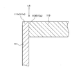
- FIG. 6 is a partial enlarged cross-sectional view showing the AA cross section in FIG. 5 in the vicinity of the opening long side portion and the lid long side portion according to the embodiment.
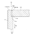
- FIG. 6 is a partial enlarged cross-sectional view showing a BB cross section in FIG. 5 in the vicinity of the short side of the opening and the short side of the lid according to the embodiment.
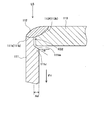
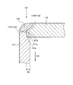
- FIG. 6 is a partially enlarged cross-sectional view showing a CC cross section in FIG. 5 in the vicinity of the opening R portion and the lid R portion according to the embodiment.
- FIG. 10 is an explanatory diagram showing a DD cross section in FIG. 9 in the vicinity of the opening long side portion and the lid long side portion according to the embodiment.
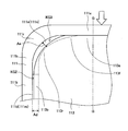
- FIG. 10 is an explanatory diagram showing an EE cross section in FIG.
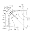
- FIG. 10 is an explanatory diagram showing an FF cross section in FIG. 9 in the vicinity of the opening R portion and the lid R portion according to the embodiment. It is explanatory drawing which concerns on embodiment and shows the state which compressed between between a pair of opening long side parts, and contact
- FIG. 14 is an explanatory diagram showing a GG section in FIG. 13 in the vicinity of the opening long side portion and the lid long side portion according to the embodiment.
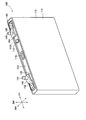
- FIGS. 1 and 2 show a lithium ion secondary battery 100 (hereinafter also simply referred to as a battery 100) according to the present embodiment.
- 3 shows the lid member 113, the positive electrode terminal 150, the negative electrode terminal 160, and the like.
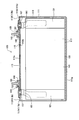
- FIG. 4 shows the main body member 111 of the battery case 110.
- FIGS. 5 to 8 show the vicinity of the opening 111 h of the main body member 111 and the lid peripheral edge 113 f of the lid member 113 in the battery case 110.
- the thickness direction BH, the width direction CH, and the height direction DH of the battery 100 are defined as the directions shown in FIGS. 1 and 2 will be described as the upper side of the battery 100, and the lower side will be described as the lower side of the battery 100.
- the battery 100 is a square sealed battery mounted on a vehicle such as a hybrid vehicle or an electric vehicle, or a battery-operated device such as a hammer drill.
- the battery 100 includes a rectangular parallelepiped battery case 110, a flat wound electrode body 120 accommodated in the battery case 110, a positive terminal 150 and a negative terminal 160 supported by the battery case 110, and the like. (See FIGS. 1 and 2).
- a non-aqueous electrolyte solution 117 is held in the battery case 110.
- the electrode body 120 is housed in the battery case 110 in a state of being laid down so that its axis (winding axis) is parallel to the width direction CH of the battery 100 (see FIG. 2).
- the electrode body 120 is formed by stacking a strip-shaped positive electrode plate 121 and a strip-shaped negative electrode plate 131 with each other through two strip-shaped separators 141, 141, winding them around an axis, and compressing them in a flat shape.
- a part of the positive electrode plate 121 in the width direction protrudes from the separators 141 and 141 in a spiral shape on one side (left side in FIG. 2) in the axial direction, and the positive electrode terminal (positive electrode terminal member) 150 and Connected.
- a part of the negative electrode plate 131 in the width direction protrudes from the separators 141 and 141 in a spiral shape on the other side in the axial direction (rightward in FIG. 2), and the negative electrode terminal (negative electrode terminal member) described above. 160 is connected.
- the battery case 110 is made of metal (specifically, aluminum).
- the battery case 110 has a bottomed rectangular tube-shaped main body member 111 having a rectangular opening 111h only on the upper side, and a rectangular plate shape that is inserted into the opening 111h of the main body member 111 and seals the opening 111h. And a lid member 113 (see FIGS. 1 to 4).
- the rectangular opening 111h of the main body member 111 includes a pair of long opening sides 111a and 111a, a pair of short opening sides 111b and 111b, and a long opening 111a and a short opening 111b. It is composed of four opening R portions 111r and 111r that are connected to each other and bend in an arc shape (see FIGS. 4 to 8).
- Each opening R portion 111r protrudes inward over the entire opening R portion 111r with respect to the circumferential direction SH of the opening portion 111h, and the lid R portion 113r of the lid peripheral portion 113f, which will be described later, of the inserted lid member 113 is lowered below. It has the support protrusion part 111e supported from.
- the support protrusion 111 e has a support plane 111 n that supports the lid R portion 113 r of the cover member 113 from below, and the support protrusion 111 e extends to the bottom 111 g of the main body member 111.
- the support plane 111n is a plane orthogonal to the depth direction FH of the main body member 111 (a plane orthogonal to the inner peripheral surface of the opening R portion 111r) over the entire circumferential direction SH of the opening R portion 111r.
- each of the short opening sides 111b covers the entire opening short side 111b in the circumferential direction SH of the opening 111h and is lower in the depth direction FH than the support protrusion 111e (positioned downward) and faces inward.
- the lower protrusion 111 d has a lower inclined surface 111 m that does not come into contact with the lid member 113, and the lower protrusion 111 d extends to the bottom 111 g of the main body member 111.
- the lower inclined surface 111m protrudes diagonally inward from the same position as the support plane 111n in the depth direction FH over the entire circumferential direction SH of the opening short side portion 111b, and becomes lower in the depth direction FH toward the inner side ( It is a plane that falls downward as it goes inward.
- a non-returnable safety valve 113v is provided near the center in the longitudinal direction (the width direction CH of the battery 100) (see FIGS. 1 to 3). Further, in the vicinity of the safety valve 113v, a liquid injection hole 113h used when injecting the electrolytic solution 117 into the battery case 110 is provided, and is hermetically sealed with a sealing member 115.
- a positive electrode terminal (positive electrode terminal member) 150 and a negative electrode terminal (negative electrode terminal member) 160 that are extended from the inside of the battery case 110 to the outside of the lid member 113 are fixed in the vicinity of both ends in the longitudinal direction. It is installed.
- each of the positive electrode terminal 150 and the negative electrode terminal 160 is connected to the electrode body 120 in the battery case 110, and passes through the lid member 113 and extends to the outside of the battery case 110. It comprises members 151 and 161, and crank-shaped second terminal members 152 and 162 disposed on the lid member 113 and fastened and fixed to the first terminal members 151 and 161.
- the positive electrode terminal 150 and the negative electrode terminal 160 are resin disposed on the inner side (the inner side of the case) of the lid member 113 together with metal fastening members 155 and 165 for fastening connection terminals outside the battery, such as bus bars and crimp terminals.
- the first insulating members 157 and 167 made of resin and the second insulating members 158 and 168 made of resin disposed on the outer side (outside of the case) of the lid member 113 are fixed to the lid member 113.
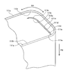
- the lid peripheral portion 113f of the lid member 113 includes a pair of lid long side portions 113a and 113a, a pair of lid short side portions 113b and 113b, and a space between the lid long side portion 113a and the lid short side portion 113b. It is composed of four lid R portions 113r and 113r that are connected and bend in an arc shape (see FIGS. 5 to 8). Among these, the lid long sides 113a and 113a are opposed to the opening long sides 111a and 111a of the main body member 111, respectively. The lid short sides 113b and 113b are opposed to the opening short sides 111b and 111b of the main body member 111, respectively. The lid R portions 113r and 113r are opposed to the opening R portions 111r and 111r of the main body member 111, respectively.
- the opening long side portions 111a and 111a and the lid long side portions 113a and 113a are in close contact with each other without forming a gap.
- the opening short side portions 111b and 111b and the lid short side portions 113b and 113b are separated from each other via a very small gap KG2.
- the opening R portions 111r and 111r and the lid R portions 113r and 113r are separated from each other via a gap KG3 larger than the gap KG2.
- the curvature radii r2 (see FIG. 9) of the lid R portions 113r and 113r are larger than the curvature radii r1 of the opening R portions 111r and 111r, respectively. For this reason, it is possible to reliably provide the gap KG3 between the opening R portion 111r and the lid R portion 113r.
- the protruding protrusion Ae of the support protrusion 111e of the opening R portion 111r is larger than the gap KG3 between the opening R portion 111r and the lid R portion 113r.
- the lower protrusion 111d of the opening short side 111b has a protrusion dimension Ad larger than the gap KG2 between the opening short side 111b and the lid short side 113b.
- the main body member 111 and the lid member 113 are joined to each other by welding. Specifically, the energy beam irradiated from the outside in the thickness direction of the lid member 113 (from the upper side of the lid member 113) to the opening 111h of the main body member 111 and the lid peripheral edge 113f of the lid member 113, as will be described later.
- the entire circumference is welded by LS (specifically, a laser beam). That is, the opening 111h and the lid peripheral portion 113f are hermetically sealed via the melt-solidified portion 112 having a square shape in plan view that is solidified after a part of the opening 111h and a portion of the lid peripheral portion 113f are once melted. It is joined.
- the cover member 113 inserted into the opening 111h of the main body member 111 has the support protrusions 111e and 111e of the opening R portions 111r and 111r. By being engaged with 113r and 113r, respectively, it is supported in the opening 111h.
- the opening short side parts 111b and 111b have the low level protrusion parts 111d and 111d, respectively, this low level protrusion part 111d is lower than the support protrusion part 111e.
- the lower protruding portion 111d contacts the lid short side portion 113b of the lid member 113, interferes with the support of the lid member 113 at the opening R portion 111r, and changes the position of the lid member 113 in the depth direction FH. There is nothing. Therefore, the position of the lid member 113 in the depth direction FH can be appropriately determined and welding can be performed.
- the support protrusion 111e of the opening R portion 111r protrudes inward over the entire circumferential direction SH of the opening R portion 111r. For this reason, in order to weld the opening R portion 111r and the lid R portion 113r, when the energy beam LS is irradiated from the outside in the thickness direction of the lid member 113, the gap R KG3 between the opening R portion 111r and the lid R portion 113r is used. Even if the energy beam LS enters, the energy beam LS hits the support protrusion 111e. Therefore, the energy beam LS can be prevented from entering the main body member 111 directly. Therefore, when welding the opening R portion 111r and the lid R portion 113r, it is possible to prevent the energy beam LS from entering the main body member 111 and causing problems such as damage to the electrode body 120.
- the lower protrusion 111d of the opening short side 111b also protrudes inward over the entire circumferential direction SH of the opening short side 111b. For this reason, when the energy beam LS is irradiated from the outside of the lid member 113 in the thickness direction in order to weld the opening short side portion 111b and the lid short side portion 113b, the opening short side portion 111b and the lid short side portion 113b Even if the energy beam LS enters through the gap KG2, the energy beam LS hits the lower protrusion 111d. Therefore, the energy beam LS can be prevented from directly entering the main body member 111 here as well. Therefore, even when welding the short opening side 111b and the short cover side 113b, it is possible to prevent the energy beam LS from entering the main body member 111 and causing problems such as damage to the electrode body 120. .
- the opening long side portion 111a does not have a portion protruding inward.
- the opening long side portion 111a and the lid long side portion 113a are hermetically welded over the entire circumference of the lid member 113 in a state where the opening long side portion 111a and the lid long side portion 113a are in close contact with each other. Therefore, it is possible to prevent the energy beam LS from entering the main body member 111 during the welding.
- the protrusion dimension Ae of the support protrusion 111e is larger than the gap KG3 between the opening R part 111r and the lid R part 113r, and the protrusion dimension Ad of the lower protrusion 111d is set to be shorter than the opening short side part 111b. It is larger than the gap KG2 with the lid short side portion 113b.
- the lower protrusion 111d has a lower inclined surface 111m over the entire circumferential direction SH of the opening short side 111b, and the lower inclined surface 111m is lower than the support plane 111n of the support protrusion 111e. Therefore, it does not contact the lid member 113. For this reason, the lower protrusion 111d does not change the position of the lid member 113 in the depth direction FH.
- the two support protrusions 111e, 111e and the lower protrusion 111d between them have a configuration in which the lower inclined surface 111m is sandwiched between the two support planes 111n, 111n, so that while forming the lower inclined surface 111m, Differences in position and form from the two support planes 111n and 111n can be reduced.
- the lower inclined surface 111m can be easily formed between the two support planes 111n and 111n by drawing, pressing, or the like, and the inexpensive main body member 111 and the inexpensive battery 100 can be obtained.
- the inclination angle ⁇ of the lower inclined surface 111m is set to 45 degrees or less, the energy beam LS reflected by the lower inclined surface 111m is difficult to enter the main body member 111 during welding, and damage to the electrode body 120 and the like are appropriate. The battery can be prevented.
- the lid member 113 the first terminal members 151 and 161, the second terminal members 152 and 162, the fastening members 155 and 165, the first insulating members 157 and 167, and the second insulating members 158 and 168 are provided. Prepare each. And using these, the positive electrode terminal 150 and the negative electrode terminal 160 are respectively fixed to the lid member 113 (see FIG. 3).
- the positive electrode terminal 150 and the negative electrode terminal 160 are connected (welded) to the separately formed electrode body 120.
- the main body member 111 is prepared.
- the electrode body 120 is accommodated in the main body member 111, and the lid member 113 is inserted into the opening 111h of the main body member 111 (see FIGS. 9 to 12).
- the lid R portions 113r and 113r of the lid member 113 are supported by the support protrusions 111e and 111e of the opening R portions 111r and 111r of the main body member 111, respectively.
- a gap is formed around the entire circumference between the opening 111 h of the main body member 111 and the lid peripheral edge 113 f of the lid member 113.
- the opening long side portions 111a and 111a and the lid long side portions 113a and 113a are arranged apart from each other via the gap KG1.
- the opening short side portions 111b and 111b and the cover short side portions 113b and 113b are arranged apart from each other through the gap KG2.
- the opening R portions 111r and 111r and the lid R portions 113r and 113r are arranged apart from each other via the gap KG3.
- the opening 111h and the lid peripheral edge 113f collide with each other or come into strong contact with each other to generate foreign matters such as metal powder. Can be prevented.
- the protrusion dimension Ae of the support protrusion 111e of the opening R portion 111r is larger than the gap KG3 between the opening R portion 111r and the lid R portion 113r.
- the protrusion dimension Ad of the lower protrusion 111d of the opening short side 111b is larger than the gap KG2 between the opening short side 111b and the lid short side 113b. Therefore, it is possible to prevent the energy beam LS from directly entering the main body member 111 through the gaps KG3 and KG2 in the welding process described below.
- the pair of long opening side portions 111a and 111a of the main body member 111 are pressed inward (compressed between the long opening side portions 111a and 111a).
- the opening long sides 111a and 111a and the pair of lid long sides 113a and 113a of the lid member 113 are brought into close contact with each other (see FIGS. 13 and 14).
- an energy beam specifically, a laser beam
- LS is irradiated to weld the opening 111h of the main body member 111 and the lid peripheral edge 113f of the lid member 113 over the entire circumference.
- a fiber laser using an optical fiber as a medium was used as a CW laser (Continuous wave laser) that continuously emits laser light.
- CW laser Continuous wave laser
- a part of the opening 111h and a part of the lid peripheral edge 113f are melted and then solidified to form a melt-solidified part 112 having a square shape in plan view, and the opening 111h is formed via the melt-solidified part 112.
- the lid peripheral edge 113f are hermetically joined over the entire circumference.
- the electrolytic solution 117 is injected into the battery case 110 through the injection hole 113h, and the injection hole 113h is hermetically sealed with the sealing member 115. Thereafter, the battery 100 is subjected to initial charging, aging, and various inspections. Thus, the battery 100 is completed.
- the support protrusions 111e and 111e of the opening R portions 111r and 111r are formed.
- the lid member 113 is supported in the opening 111h by engaging with the lid R portions 113r and 113r, respectively.
- the opening short side parts 111b and 111b have the low level protrusion parts 111d and 111d, respectively, this low level protrusion part 111d is lower than the support protrusion part 111e.
- the lower protruding portion 111d contacts the lid short side portion 113b of the lid member 113, interferes with the support of the lid member 113 at the opening R portion 111r, and changes the position of the lid member 113 in the depth direction FH. There is nothing. Therefore, the welding process can be performed by appropriately determining the position of the lid member 113 in the depth direction FH.
- the support protrusion 111e of the opening R portion 111r protrudes inward over the entire circumferential direction SH of the opening R portion 111r. For this reason, in the welding process, in order to weld the opening R portion 111r and the lid R portion 113r, the thickness direction of the lid member 113 with the gap KG3 formed between the opening R portion 111r and the lid R portion 113r.
- the energy beam LS is irradiated from the outside, the energy beam LS hits the support protrusion 111e. Therefore, the energy beam LS can be prevented from entering the main body member 111 directly. Therefore, when welding the opening R portion 111r and the lid R portion 113r, it is possible to prevent the energy beam LS from entering the main body member 111 and causing problems such as damage to the electrode body 120.
- the lower protrusion 111d of the opening short side 111b also protrudes inward over the entire circumferential direction SH of the opening short side 111b. For this reason, in the welding process, in order to weld the opening short side portion 111b and the lid short side portion 113b, the lid member with the gap KG2 formed between the opening short side portion 111b and the lid short side portion 113b.
- the energy beam LS is irradiated from the outside in the thickness direction of the 113, the energy beam LS hits the lower protrusion 111d. Therefore, the energy beam LS can be prevented from directly entering the main body member 111 here as well.
- the electrode body 120 due to the incidence of the energy beam LS is provided even though the gaps KG3 and KG2 are provided between the opening R portion 111r and the lid R portion 113r and between the opening short side portion 111b and the lid short side portion 113b. Can be manufactured.
- the projecting dimension Ae of the support projecting part 111e is larger than the gap KG3 between the opening R part 111r and the lid R part 113r, and the projecting dimension Ad of the lower projecting part 111d is set to the short side of the opening. It is larger than the gap KG2 between the portion 111b and the lid short side portion 113b.
- the lower protrusion 111d has a lower inclined surface 111m over the entire circumferential direction SH of the opening short side 111b, and the lower inclined surface 111m is a support plane of the support protrusion 111e. Since it is lower than 111n, it does not contact the lid member 113. For this reason, the lower protrusion 111d does not change the position of the lid member 113 in the depth direction FH.
- the two support protrusions 111e, 111e and the lower protrusion 111d between them have a configuration in which the lower inclined surface 111m is sandwiched between the two support planes 111n, 111n, so that while forming the lower inclined surface 111m, Differences in position and form from the two support planes 111n and 111n can be reduced.
- the lower inclined surface 111m can be easily formed between the two support planes 111n and 111n by drawing, pressing, or the like, and the inexpensive main body member 111 and thus the inexpensive square battery 100 can be manufactured.
- the inclination angle ⁇ of the lower inclined surface 111m is set to 45 degrees or less, the energy beam LS reflected by the lower inclined surface 111m is difficult to enter the main body member 111 during welding, and damage to the electrode body 120 and the like are appropriate.
- the square battery 100 can be manufactured.
- the lid peripheral edge 113f of the lid member 113 collides with or strongly contacts the opening 111h, foreign matter such as metal powder is generated, It may fall into the main body member 111 and cause a short circuit or the like. Therefore, in the present embodiment, when the main body member 111 is in a free state without pressing or restraining, the gap KG1 is generated between the opening long side portion 111a and the lid long side portion 113a.
- the energy beam LS is directly incident on the main body member 111 from the gap KG1 between the opening long side 111a and the lid long side 113a. There is a risk that problems such as damage to the electrode body 120 may occur.
- the opening 111h and the lid peripheral edge 113f are hermetically welded over the entire circumference in a state where the opening long side 111a and the lid long side 113a are in close contact with each other. Therefore, the energy beam LS does not directly enter the main body member 111, and it is possible to further reduce the possibility of causing problems such as damage to the electrode body 120.
- Lithium ion secondary battery (square battery) 110
- Battery case 111
- Main body member 111h Opening portion 111a Opening long side portion 111b Opening short side portion 111r Opening R portion 111d
- Lower protruding portion 111m Lower inclined surface 111e
- Support protruding portion 111n
- Support flat surface 112
- Melting and solidifying portion 113 Lid member 113f Lid peripheral portion 113a Lid long side part 113b Lid short side part 113r Lid R part 120
- Electrode body 150
- Positive electrode terminal positive electrode terminal member
- Negative terminal negative terminal member
- Ae Projection size Ad (of the support projection)
- Projection size KG1, KG2, KG3 Clearance LS Energy beam (laser beam)
- SH main body member)
- SH Opening) circumferential direction
Landscapes
- Engineering & Computer Science (AREA)
- Optics & Photonics (AREA)
- Physics & Mathematics (AREA)
- Mechanical Engineering (AREA)
- General Chemical & Material Sciences (AREA)
- Chemical & Material Sciences (AREA)
- Chemical Kinetics & Catalysis (AREA)
- Electrochemistry (AREA)
- Plasma & Fusion (AREA)
- Manufacturing & Machinery (AREA)
- Sealing Battery Cases Or Jackets (AREA)
- Laser Beam Processing (AREA)
- Connection Of Batteries Or Terminals (AREA)
Abstract
Description
110 電池ケース
111 本体部材
111h 開口部
111a 開口長辺部
111b 開口短辺部
111r 開口R部
111d 低位突出部
111m 低位傾斜面
111e 支持突出部
111n 支持平面
112 溶融固化部
113 蓋部材
113f 蓋周縁部
113a 蓋長辺部
113b 蓋短辺部
113r 蓋R部
120 電極体
150 正極端子(正極端子部材)
160 負極端子(負極端子部材)
Ae (支持突出部の)突出寸法
Ad (低位突出部の)突出寸法
KG1,KG2,KG3 隙間
LS エネルギビーム(レーザビーム)
FH (本体部材の)深さ方向
SH (開口部の)周方向
Claims (8)
- 直方体状をなす金属製の電池ケース内に電極体を収容してなる角型電池であって、
前記電池ケースは、
一対の開口長辺部、一対の開口短辺部、及び、前記開口長辺部と前記開口短辺部との間をそれぞれ結んで弧状に曲がる4つの開口R部からなる矩形状の開口部を有する、有底角筒状の本体部材と、
前記開口部内に挿入されて前記開口部を封口してなり、一対の前記開口長辺部にそれぞれ対向する一対の蓋長辺部、一対の前記開口短辺部にそれぞれ対向する一対の蓋短辺部、及び、4つの前記開口R部にそれぞれ対向する4つの蓋R部からなる蓋周縁部を有する、矩形板状の蓋部材と、を有し、
前記本体部材の前記開口部のうち、
4つの前記開口R部は、
前記開口部の周方向について前記開口R部全体にわたり、内側に向けて突出し、挿入された前記蓋部材を支持する支持突出部をそれぞれ有し、
一対の前記開口短辺部は、
前記開口部の前記周方向について前記開口短辺部全体にわたり、前記支持突出部よりも前記本体部材の深さ方向に低位で、内側に向けて突出する低位突出部をそれぞれ有し、
4つの前記開口R部と前記蓋R部とは、
これらの間それぞれに隙間を有し、
前記蓋部材の厚み方向外側から照射されたエネルギビームによりそれぞれ溶接されてなり、
一対の前記開口短辺部と前記蓋短辺部とは、
これらの間の少なくともいずれかに隙間を有し、
前記エネルギビームによりそれぞれ溶接されてなる
角型電池。 - 請求項1に記載の角型電池であって、
前記支持突出部は、前記開口R部と前記蓋R部との前記隙間よりも、突出寸法が大きくされてなり、
前記低位突出部は、前記開口短辺部と前記蓋短辺部との前記隙間よりも、突出寸法が大きくされてなる
角型電池。 - 請求項1または請求項2に記載の角型電池であって、
前記支持突出部は、前記周方向について前記開口R部全体にわたり、前記深さ方向に直交し、前記蓋部材を支持する支持平面を含み、
前記低位突出部は、前記周方向について前記開口短辺部全体にわたり、前記支持平面と同じ位置から内側に斜めに突出し、前記深さ方向の位置が内側ほど前記深さ方向に低位となる低位傾斜面を含み、
前記低位傾斜面が前記支持平面となす角度αを45度以下としてなる
角型電池。 - 請求項1~請求項3のいずれか一項に記載の角型電池であって、
前記本体部材の前記開口部と前記蓋部材の前記蓋周縁部とは、
一対の前記開口長辺部と前記蓋長辺部とがそれぞれ互いに密着した状態で、前記蓋部材の全周にわたり気密に溶接されてなる
角型電池。 - 直方体状をなす金属製の電池ケース内に電極体を収容してなり、
前記電池ケースは、
一対の開口長辺部、一対の開口短辺部、及び、前記開口長辺部と前記開口短辺部との間をそれぞれ結んで弧状に曲がる4つの開口R部からなる矩形状の開口部を有する、有底角筒状の本体部材と、
前記開口部内に挿入されて前記開口部を封口してなり、一対の前記開口長辺部にそれぞれ対向する一対の蓋長辺部、一対の前記開口短辺部にそれぞれ対向する一対の蓋短辺部、及び、4つの前記開口R部にそれぞれ対向する4つの蓋R部からなる蓋周縁部を有する、矩形板状の蓋部材と、を有し、
前記本体部材の前記開口部のうち、
4つの前記開口R部は、
前記開口部の周方向について前記開口R部全体にわたり、内側に向けて突出し、挿入された前記蓋部材を支持する支持突出部をそれぞれ有し、
一対の前記開口短辺部は、
前記開口部の前記周方向について前記開口短辺部全体にわたり、前記支持突出部よりも前記本体部材の深さ方向に低位で、内側に向けて突出する低位突出部をそれぞれ有し、
4つの前記開口R部と前記蓋R部とは、
これらの間それぞれに隙間を有し、
前記蓋部材の厚み方向外側から照射されたエネルギビームによりそれぞれ溶接されてなり、
一対の前記開口短辺部と前記蓋短辺部とは、
これらの間の少なくともいずれかに隙間を有し、
前記エネルギビームによりそれぞれ溶接されてなる
角型電池の製造方法であって、
前記本体部材の前記開口部内に前記蓋部材を挿入し、前記蓋部材の前記蓋R部を前記本体部材の前記開口R部の前記支持突出部に支持させる挿入支持工程と、
4つの前記開口R部と前記蓋R部との間にそれぞれ前記隙間を生じた状態、かつ、一対の前記開口短辺部と前記蓋短辺部との間の少なくともいずれかに前記隙間を生じた状態で、前記エネルギビームを照射して、4つの前記開口R部と前記蓋R部とをそれぞれ溶接し、一対の前記開口短辺部と前記蓋短辺部とをそれぞれ溶接する溶接工程と、を備える
角型電池の製造方法。 - 請求項5に記載の角型電池の製造方法であって、
前記支持突出部は、前記開口R部と前記蓋R部との前記隙間よりも、突出寸法が大きくされてなり、
前記低位突出部は、前記開口短辺部と前記蓋短辺部との前記隙間よりも、突出寸法が大きくされてなる
角型電池の製造方法。 - 請求項5または請求項6に記載の角型電池の製造方法であって、
前記支持突出部は、前記周方向について前記開口R部全体にわたり、前記深さ方向に直交し、前記蓋部材を支持する支持平面を含み、
前記低位突出部は、前記周方向について前記開口短辺部全体にわたり、前記支持平面と同じ位置から内側に斜めに突出し、前記深さ方向の位置が内側ほど前記深さ方向に低位となる低位傾斜面を含み、
前記低位傾斜面が前記支持平面となす角度αを45度以下としてなる
角型電池の製造方法。 - 請求項5~請求項7のいずれか一項に記載の角型電池の製造方法であって、
前記溶接工程は、
一対の前記開口長辺部同士間を圧縮して、前記開口長辺部と前記蓋長辺部とをそれぞれ互いに密着させた状態で、前記開口部と前記蓋周縁部とを全周にわたり気密に溶接する工程である
角型電池の製造方法。
Priority Applications (4)
| Application Number | Priority Date | Filing Date | Title |
|---|---|---|---|
| KR1020147029315A KR101510067B1 (ko) | 2012-06-28 | 2013-04-24 | 각형 전지 및 각형 전지의 제조 방법 |
| EP13808586.5A EP2869357B1 (en) | 2012-06-28 | 2013-04-24 | Rectangular battery and rectangular battery manufacturing method |
| CN201380033398.2A CN104412408B (zh) | 2012-06-28 | 2013-04-24 | 方型电池和方型电池的制造方法 |
| US14/410,148 US9370844B2 (en) | 2012-06-28 | 2013-04-24 | Rectangular battery and rectangular battery manufacturing method |
Applications Claiming Priority (2)
| Application Number | Priority Date | Filing Date | Title |
|---|---|---|---|
| JP2012145124A JP5480335B2 (ja) | 2012-06-28 | 2012-06-28 | 角型電池及び角型電池の製造方法 |
| JP2012-145124 | 2012-06-28 |
Publications (1)
| Publication Number | Publication Date |
|---|---|
| WO2014002600A1 true WO2014002600A1 (ja) | 2014-01-03 |
Family
ID=49782775
Family Applications (1)
| Application Number | Title | Priority Date | Filing Date |
|---|---|---|---|
| PCT/JP2013/062129 Ceased WO2014002600A1 (ja) | 2012-06-28 | 2013-04-24 | 角型電池及び角型電池の製造方法 |
Country Status (6)
| Country | Link |
|---|---|
| US (1) | US9370844B2 (ja) |
| EP (1) | EP2869357B1 (ja) |
| JP (1) | JP5480335B2 (ja) |
| KR (1) | KR101510067B1 (ja) |
| CN (1) | CN104412408B (ja) |
| WO (1) | WO2014002600A1 (ja) |
Cited By (2)
| Publication number | Priority date | Publication date | Assignee | Title |
|---|---|---|---|---|
| EP3132883A4 (en) * | 2014-04-15 | 2017-06-28 | Panasonic Intellectual Property Management Co., Ltd. | Laser welding method |
| JP7570160B1 (ja) * | 2024-05-10 | 2024-10-21 | 株式会社大北製作所 | 箱体の製造方法 |
Families Citing this family (17)
| Publication number | Priority date | Publication date | Assignee | Title |
|---|---|---|---|---|
| JP5869435B2 (ja) | 2012-06-27 | 2016-02-24 | トヨタ自動車株式会社 | 角型電池及び角型電池の製造方法 |
| JP6127763B2 (ja) * | 2013-06-18 | 2017-05-17 | トヨタ自動車株式会社 | 密閉型電池およびその製造方法 |
| WO2015146591A1 (ja) * | 2014-03-27 | 2015-10-01 | プライムアースEvエナジー 株式会社 | レーザ溶接装置、レーザ溶接方法及び電池ケース |
| JP6416696B2 (ja) * | 2015-05-25 | 2018-10-31 | トヨタ自動車株式会社 | ケース本体と蓋体との溶接方法および該方法を用いた電池の製造方法 |
| JP6213784B2 (ja) * | 2015-06-12 | 2017-10-18 | トヨタ自動車株式会社 | 密閉型電池 |
| JP6085058B1 (ja) * | 2016-08-02 | 2017-02-22 | 冨士発條株式会社 | 電池缶及び電池 |
| DE102018120389A1 (de) * | 2018-08-21 | 2020-02-27 | Kirchhoff Automotive Deutschland Gmbh | Baugruppe sowie Batteriegehäuse mit mehreren dieser Baugruppen |
| CN109175744A (zh) * | 2018-10-15 | 2019-01-11 | 仪征常众汽车部件有限公司 | 一种用于新能源电动汽车中冷却箱的焊接工艺 |
| JP7119988B2 (ja) | 2018-12-26 | 2022-08-17 | 東洋製罐株式会社 | 角形缶の製造方法 |
| JP7444648B2 (ja) | 2020-03-12 | 2024-03-06 | 大和製罐株式会社 | 電池ケースおよびその製造方法 |
| JP7562591B2 (ja) * | 2022-03-18 | 2024-10-07 | プライムプラネットエナジー&ソリューションズ株式会社 | 電池ケース、および該電池ケースを備える二次電池 |
| JP7555988B2 (ja) | 2022-03-18 | 2024-09-25 | プライムプラネットエナジー&ソリューションズ株式会社 | 電池ケース、および該電池ケースを備える二次電池 |
| JP7713976B2 (ja) * | 2023-01-24 | 2025-07-28 | プライムプラネットエナジー&ソリューションズ株式会社 | 蓄電デバイスの製造方法 |
| KR20250123184A (ko) * | 2023-01-31 | 2025-08-14 | 컨템포러리 엠퍼렉스 테크놀로지 씨오., 리미티드 | 전지 셀, 전지 및 전기 장치 |
| WO2024253383A1 (ko) * | 2023-06-07 | 2024-12-12 | 주식회사 엘지에너지솔루션 | 전지 캔과 집전판과 캡의 용접 구조 및 이를 적용한 배터리 셀 |
| WO2025029095A1 (ko) * | 2023-08-03 | 2025-02-06 | 주식회사 엘지에너지솔루션 | 배터리 셀 및 배터리 셀의 제조 방법 |
| KR20250134293A (ko) * | 2024-03-04 | 2025-09-11 | 에스케이온 주식회사 | 지지부를 포함하는 배터리 셀 |
Citations (3)
| Publication number | Priority date | Publication date | Assignee | Title |
|---|---|---|---|---|
| JPH11219688A (ja) | 1998-02-02 | 1999-08-10 | Fuji Elelctrochem Co Ltd | 角形電気化学素子用の外装容器およびその外装容器を用いた角形電気化学素子の製造方法 |
| JP2001135282A (ja) * | 1999-11-04 | 2001-05-18 | Nec Mobile Energy Kk | 密閉型電池 |
| JP2011204396A (ja) * | 2010-03-24 | 2011-10-13 | Sanyo Electric Co Ltd | 密閉型電池とその製造方法 |
Family Cites Families (10)
| Publication number | Priority date | Publication date | Assignee | Title |
|---|---|---|---|---|
| JP3015667B2 (ja) * | 1994-05-31 | 2000-03-06 | 三洋電機株式会社 | 密閉形の角形電池 |
| US20020150817A1 (en) * | 2001-04-13 | 2002-10-17 | Grubb Kenneth L. | Low profile battery termination |
| JP4786159B2 (ja) * | 2004-09-22 | 2011-10-05 | 日産自動車株式会社 | 電池収納容器及びその組立方法 |
| KR100796097B1 (ko) * | 2004-10-26 | 2008-01-21 | 닛산 지도우샤 가부시키가이샤 | 배터리 모듈 |
| KR100709834B1 (ko) * | 2005-04-26 | 2007-04-23 | 삼성에스디아이 주식회사 | 이차 전지 |
| JP4803023B2 (ja) * | 2006-12-26 | 2011-10-26 | トヨタ自動車株式会社 | 電池及び電池の製造方法、並びに電池を搭載した車両 |
| US8492022B2 (en) * | 2009-10-07 | 2013-07-23 | Samsung Sdi Co., Ltd. | Rechargeable battery with buffer sheet between electrode assembly and battery case |
| JP2012079476A (ja) * | 2010-09-30 | 2012-04-19 | Sanyo Electric Co Ltd | 角形密閉型電池の製造方法 |
| JP5672937B2 (ja) * | 2010-10-18 | 2015-02-18 | 住友電気工業株式会社 | 溶融塩電池及び溶融塩電池連結体 |
| JP5987465B2 (ja) * | 2011-06-17 | 2016-09-07 | 株式会社Gsユアサ | 蓄電素子及びその製造方法 |
-
2012
- 2012-06-28 JP JP2012145124A patent/JP5480335B2/ja active Active
-
2013
- 2013-04-24 WO PCT/JP2013/062129 patent/WO2014002600A1/ja not_active Ceased
- 2013-04-24 CN CN201380033398.2A patent/CN104412408B/zh active Active
- 2013-04-24 EP EP13808586.5A patent/EP2869357B1/en active Active
- 2013-04-24 US US14/410,148 patent/US9370844B2/en active Active
- 2013-04-24 KR KR1020147029315A patent/KR101510067B1/ko active Active
Patent Citations (3)
| Publication number | Priority date | Publication date | Assignee | Title |
|---|---|---|---|---|
| JPH11219688A (ja) | 1998-02-02 | 1999-08-10 | Fuji Elelctrochem Co Ltd | 角形電気化学素子用の外装容器およびその外装容器を用いた角形電気化学素子の製造方法 |
| JP2001135282A (ja) * | 1999-11-04 | 2001-05-18 | Nec Mobile Energy Kk | 密閉型電池 |
| JP2011204396A (ja) * | 2010-03-24 | 2011-10-13 | Sanyo Electric Co Ltd | 密閉型電池とその製造方法 |
Non-Patent Citations (1)
| Title |
|---|
| See also references of EP2869357A4 |
Cited By (3)
| Publication number | Priority date | Publication date | Assignee | Title |
|---|---|---|---|---|
| EP3132883A4 (en) * | 2014-04-15 | 2017-06-28 | Panasonic Intellectual Property Management Co., Ltd. | Laser welding method |
| US11020820B2 (en) | 2014-04-15 | 2021-06-01 | Panasonic Intellectual Property Management Co., Ltd. | Laser welding method |
| JP7570160B1 (ja) * | 2024-05-10 | 2024-10-21 | 株式会社大北製作所 | 箱体の製造方法 |
Also Published As
| Publication number | Publication date |
|---|---|
| JP5480335B2 (ja) | 2014-04-23 |
| CN104412408A (zh) | 2015-03-11 |
| EP2869357A4 (en) | 2016-07-06 |
| EP2869357B1 (en) | 2018-05-23 |
| US20150318517A1 (en) | 2015-11-05 |
| KR101510067B1 (ko) | 2015-04-07 |
| CN104412408B (zh) | 2016-04-20 |
| US9370844B2 (en) | 2016-06-21 |
| KR20140130242A (ko) | 2014-11-07 |
| JP2014010936A (ja) | 2014-01-20 |
| EP2869357A1 (en) | 2015-05-06 |
Similar Documents
| Publication | Publication Date | Title |
|---|---|---|
| JP5480335B2 (ja) | 角型電池及び角型電池の製造方法 | |
| JP6138963B2 (ja) | 角形電池 | |
| US9455424B2 (en) | Battery container and its manufacturing method | |
| JP5869435B2 (ja) | 角型電池及び角型電池の製造方法 | |
| CN103378318B (zh) | 装置箱体及装置箱体的制造方法 | |
| JP6657843B2 (ja) | 二次電池 | |
| JP5225805B2 (ja) | 二次電池およびその製造方法 | |
| JP6599129B2 (ja) | 角形二次電池及びそれを用いた組電池、並びにその製造方法 | |
| JP5492653B2 (ja) | 二次電池 | |
| JP6085058B1 (ja) | 電池缶及び電池 | |
| KR101664647B1 (ko) | 전지 및 그 제조 방법 | |
| JP5691998B2 (ja) | 電池ケース | |
| JP2012009319A (ja) | 二次電池および組電池 | |
| JP5937483B2 (ja) | 電池及び電池の製造方法 | |
| CN116207333A (zh) | 二次电池以及电池组、及其制造方法 | |
| JP4259558B2 (ja) | 電池及び電池の製造方法 | |
| JP6031958B2 (ja) | 密閉容器及び密閉容器の製造方法 | |
| JP2010205441A (ja) | 角形密閉電池の製造方法及び角形密閉電池 | |
| JP6331753B2 (ja) | 電池用ケース | |
| JP2007329076A (ja) | 電池の製造方法及び電池 | |
| JP2007328940A (ja) | 電池の製造方法及び弁部材 |
Legal Events
| Date | Code | Title | Description |
|---|---|---|---|
| WWE | Wipo information: entry into national phase |
Ref document number: 201380033398.2 Country of ref document: CN |
|
| 121 | Ep: the epo has been informed by wipo that ep was designated in this application |
Ref document number: 13808586 Country of ref document: EP Kind code of ref document: A1 |
|
| ENP | Entry into the national phase |
Ref document number: 20147029315 Country of ref document: KR Kind code of ref document: A |
|
| WWE | Wipo information: entry into national phase |
Ref document number: 14410148 Country of ref document: US Ref document number: 2013808586 Country of ref document: EP |
|
| NENP | Non-entry into the national phase |
Ref country code: DE |