WO2014002709A1 - 液面検出装置 - Google Patents
液面検出装置 Download PDFInfo
- Publication number
- WO2014002709A1 WO2014002709A1 PCT/JP2013/065522 JP2013065522W WO2014002709A1 WO 2014002709 A1 WO2014002709 A1 WO 2014002709A1 JP 2013065522 W JP2013065522 W JP 2013065522W WO 2014002709 A1 WO2014002709 A1 WO 2014002709A1
- Authority
- WO
- WIPO (PCT)
- Prior art keywords
- terminal
- plate
- electric cord
- liquid level
- flange
- Prior art date
- Legal status (The legal status is an assumption and is not a legal conclusion. Google has not performed a legal analysis and makes no representation as to the accuracy of the status listed.)
- Ceased
Links
Images




Classifications
-
- G—PHYSICS
- G01—MEASURING; TESTING
- G01F—MEASURING VOLUME, VOLUME FLOW, MASS FLOW OR LIQUID LEVEL; METERING BY VOLUME
- G01F23/00—Indicating or measuring liquid level or level of fluent solid material, e.g. indicating in terms of volume or indicating by means of an alarm
- G01F23/30—Indicating or measuring liquid level or level of fluent solid material, e.g. indicating in terms of volume or indicating by means of an alarm by floats
- G01F23/32—Indicating or measuring liquid level or level of fluent solid material, e.g. indicating in terms of volume or indicating by means of an alarm by floats using rotatable arms or other pivotable transmission elements
- G01F23/36—Indicating or measuring liquid level or level of fluent solid material, e.g. indicating in terms of volume or indicating by means of an alarm by floats using rotatable arms or other pivotable transmission elements using electrically actuated indicating means
-
- G—PHYSICS
- G01—MEASURING; TESTING
- G01F—MEASURING VOLUME, VOLUME FLOW, MASS FLOW OR LIQUID LEVEL; METERING BY VOLUME
- G01F23/00—Indicating or measuring liquid level or level of fluent solid material, e.g. indicating in terms of volume or indicating by means of an alarm
- G01F23/30—Indicating or measuring liquid level or level of fluent solid material, e.g. indicating in terms of volume or indicating by means of an alarm by floats
- G01F23/32—Indicating or measuring liquid level or level of fluent solid material, e.g. indicating in terms of volume or indicating by means of an alarm by floats using rotatable arms or other pivotable transmission elements
- G01F23/36—Indicating or measuring liquid level or level of fluent solid material, e.g. indicating in terms of volume or indicating by means of an alarm by floats using rotatable arms or other pivotable transmission elements using electrically actuated indicating means
- G01F23/363—Indicating or measuring liquid level or level of fluent solid material, e.g. indicating in terms of volume or indicating by means of an alarm by floats using rotatable arms or other pivotable transmission elements using electrically actuated indicating means using electromechanically actuated indicating means
Definitions
- the present invention relates to a liquid level detection device.
- Patent Document 1 there is one disclosed in Patent Document 1 as a liquid level detection device that detects the position (liquid level) of various liquids (fuel, etc.) in a tank provided in a vehicle (automobile or the like).
- a liquid level detection device disclosed in Patent Document 1 includes a flange portion for fixing the liquid level detection device to a tank, and a mounting plate formed so as to hang from the flange portion. And a detection unit (gauge unit 21) for detecting the level of the liquid contained in the tank, and two electric cords (lead wires 25a and 25b) drawn from the detection unit are attached On one side of the plate, the plate is drawn toward the flange portion (see FIG. 2B of the same document).
- the present invention has been made in view of the above circumstances, and an object thereof is to provide a liquid level detection device having a configuration capable of reducing or eliminating contact between a plurality of electrical cords drawn from a detection unit.
- a plate-like flange portion that protrudes in a direction orthogonal to the back surface and is attached to a tank that contains the liquid, and First and second electric cords drawn from the detection portion toward the flange portion;
- One end portion is a connecting portion connected to the tip portion of the first electric cord on the lower surface side that is the surface on the detection portion side of the flange portion, and the other end portion is opposite to the lower surface of the flange portion.
- a first terminal that is an external connection portion that reaches the upper surface side that is a surface and can be connected to a predetermined external device;
- One end is a connecting portion connected to the tip of the second electric cord on the lower surface side of the flange portion, and the other end reaches the upper surface side of the flange portion and can be connected to the external device
- a second terminal which is an external connection part
- the mounting plate portion is provided with a branch portion including a through hole or a notch between the detection portion and the flange portion, Since the second electric cord passes through the branch portion, the second electric cord wraps around from the attachment surface side to the back surface side of the attachment plate portion, and a tip portion of the second electric cord is attached to the attachment plate portion.
- connection portion of the first terminal is located on the mounting surface side of the mounting plate portion
- connection part of the second terminal is located on the back side of the mounting plate part
- connection portion of the first terminal and the tip portion of the first electric cord are connected on the mounting surface side of the mounting plate portion
- connection part of the second terminal and the tip part of the second electric cord are connected on the back side of the mounting plate part
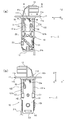
- FIG. 3A is a cross-sectional view of the frame body taken along line AA shown in FIG.
- FIG. 3B is a cross-sectional view of the frame body taken along the line BB shown in FIG. It is the figure which looked at the liquid level detection apparatus from the opening part side of the connector cover part. It is a figure for demonstrating the branch part which concerns on a modification.
- a liquid level detection apparatus according to an embodiment of the present invention will be described with reference to the drawings.
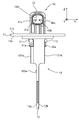
- the liquid level detection device 1 detects, for example, the position (liquid level) of various liquids (fuel, etc.) in a tank provided in a vehicle (automobile or the like), as shown in FIGS.
- the frame 10, the detection unit 20, the first electric cord 31, the second electric cord 32, the first terminal 41, and the second terminal 42 are provided.
- the first and second electric cords 31 and 32 are omitted.
- the frame body 10 is made of a predetermined resin (for example, polyacetal (POM) resin). As shown mainly in FIG. 2A, the flange portion 11, the mounting plate portion 12, and the connector cover portion 13 are provided. It is configured by being integrally formed.
- a predetermined resin for example, polyacetal (POM) resin
- the flange portion 11 is a portion that protrudes from one end (the end on the + Z direction side) of the mounting plate portion 12 and is attached to a tank (not shown) that contains a liquid such as a fuel tank.
- the flange portion 11 has a flat plate shape extending in a plane direction parallel to the XY plane.
- the liquid level detection device 1 is attached to the tank by fixing the flange portion 11 to the tank by a fixing means such as a screw.
- a portion below the flange portion 11 ( ⁇ Z direction side) is located in the tank.
- the flange portion 11 is attached to the tank via the packing 3 together with the reinforcing plate 2 disposed on the upper surface 11a (the surface facing the + Z direction). .
- the reinforcing plate 2 is made of an iron-based material or the like, and covers the flange portion 11 from the upper surface 11a.
- the packing 3 is made of a rubber material such as nitrile rubber (NBR), and is disposed on the lower surface 11b (the surface facing the ⁇ Z direction) of the flange portion 11.
- NBR nitrile rubber
- the first and second restraining portions 111 and 112 have a concave shape, and the first and second electric cords 31 and 32 do not move substantially in the X direction in the concave portions. A part of the codes 31 and 32 is suppressed. As a result, the first and second electric cords 31 and 32 and the mounting plate portion 12 are less likely to rub against each other due to vibration or the like, so that the risk of disconnection of the first and second electric cords 31 and 32 can be reduced. Further, the recessed portions of the first and second restraining portions 111 and 112 are slightly larger than the diameters of the first and second electrical cords 31 and 32, and the first and second electrical cords 31 and 32 are disposed. Has become easier.
- the first restraining portion 111 is located on the mounting surface 12a side, which will be described later, of the mounting plate portion 12, and the second restraining portion 112 is located on the back surface 12b side, which will be described later.
- the attachment plate part 12 is a part to which the detection part 20 is attached.
- the mounting plate portion 12 is provided on the lower surface 11b side of the flange portion 11, and extends in a direction orthogonal to the lower surface 11b.
- the mounting plate portion 12 has a substantially flat plate shape extending in a plane direction parallel to the YZ plane.
- the surface facing the ⁇ X direction of the mounting plate portion 12 is configured as a mounting surface 12a to which the detection unit 20 is mounted.
- a surface facing the + X direction of the mounting plate portion 12 is a back surface 12b of the mounting surface 12a.
- a restricting portion 120a (see FIG. 2 (a), FIG. 6 and the like) formed of a convex portion that restricts the detection portion 20 from being attached from the back surface 12b side is formed. . This function will be described later.
- the attachment plate portion 12 is provided with a branching portion 122 formed of a hole penetrating the attachment plate portion 12 in the X direction between the detection portion 20 and the flange portion 11. This function will be described later.
- the connector cover part 13 is provided on the upper surface 11a side of the flange part 11, and allows a part of the first and second terminals 41 and 42 to be seen outside.
- a part of the first and second terminals 41 and 42 (external connection parts 41b and 42b described later) and the connector cover part 13 constitute a connector part 50 (direct coupler part).
- the connector unit 50 can be connected to a terminal of a predetermined external device, and can thereby supply the detection signal of the detection unit 20 to the connected external device.
- the external device that has acquired the detection signal obtains the liquid remaining amount value (for example, the remaining fuel value) in the tank based on the acquired detection signal.
- the opening portion 130 of the connector cover portion 13 is open in a direction parallel to the upper surface 11a of the flange portion 11.
- the float 21a is a float formed in a substantially bowl shape from a synthetic resin, a metal material, or the like.
- the float 21a receives buoyancy from the liquid in the tank and floats on the liquid surface, and is displaced as the liquid level changes.
- the arm 21b is a rod made of metal, and a float 21a is attached to one end thereof. The other end of the arm 21b is held by the rotating unit 21.
- the detection part 20 is not attached from the back surface 12b side of the attachment plate part 12 by the restriction part 120a described above. Specifically, on the side of the mounting surface 12a of the mounting plate portion 12 and in the vicinity of each of the mounting holes H1 and H2 located at the left and right ends of the mounting plate portion 12 in FIG. By forming the portion 120a, even if it is intended to attach the detection portion 20 from the back surface 12b side and engage the claw portions C1, C2, C3 with the attachment holes H1, H2, H3, the claw portion C1. , C2 does not engage with the mounting holes H1, H2 because of the restriction portion 120a.
- a circuit board (printed circuit board) (not shown) on which a plurality of electrodes and a resistor connected to the plurality of electrodes are formed is provided.
- a contact (not shown) made of metal is provided on the back side of the rotating portion 21. When this contact comes into contact with any one of the plurality of electrodes formed on the circuit board, a resistor corresponding to the contacted electrode. Is output from the detection unit 20 as a detection signal.
- the detection unit 20 is configured as a sliding resistance type detection unit that slides the contact point on the resistance based on the operation of the arm 21b connected to the float 21a.
- the first and second electric cords 31 and 32 are electrically connected to the circuit board, and are drawn from the detection unit 20 toward the flange unit 11 (that is, in the + Z direction).
- the first electric cord 31 is configured as a GND (ground) line
- the second electric cord 32 is configured as a signal line for outputting the detection signal.
- the first electric cord 31 may be configured as a signal line
- the second electric cord 32 may be configured as a GND line.
- the first electric cord 31 is drawn from the detection unit 20 toward the flange unit 11 and is turned back halfway, so that the tip 31a faces the detection unit 20 side.
- the tip portion 31a is a portion that is not covered and the core wire is exposed, and is a portion that is connected to the first terminal 41 (a connection portion 41a described later of the first terminal 41) by soldering.
- the first electric cord 31 extends from the detection unit 20 side in the + Z direction along the wall portion 121a, and a connection portion 41a of the first terminal 41 to be described later.
- the tip portion 31a is generally directed in the ⁇ Z direction so that it is folded back at a position closer to the lower surface 11b of the flange portion 11. Thereby, the 1st electric cord 31 is bent in the shape of a claw, as shown in Drawing 3 (a). All of the first electric cords 31 are located on the mounting surface 12 a side of the mounting plate portion 12.
- a portion of the second electric cord 32 that protrudes from the branch portion 122 toward the back surface 12b extends in the direction of the flange portion 11 along the wall portion 121b, and is more flanged than a connecting portion 42a described later of the second terminal 42. 11 is folded back at a position close to the lower surface 11b of the head 11 so that the tip 32a is generally in the ⁇ Z direction. Thereby, the 2nd electric cord 32 is bent in the shape of a claw, as shown in Drawing 3 (b).
- the part before passing through the branch part 122 from the detection part 20 is located on the attachment surface 12 a side of the attachment plate part 12, and the part after passing through the branch part 122 is located on the back surface 12 b side. .
- the 2nd suppression part 112 is located near the lower surface 11b of the flange part 11 rather than the connection part 42a which the 2nd terminal 42 mentions later.
- the wall 121b also has a function of preventing the second electric cord 32 from moving in the ⁇ Y direction.
- the relationship between the first electric cord 31 and the second electric cord 32 is that all of the first electric cord 31 is located on the attachment surface 12a side of the attachment plate portion 12, while the second electric cord 32 is. Is passing through the branching portion 122, so that it wraps around from the mounting surface 12 a side of the mounting plate portion 12 to the back surface 12 b side, and the tip end portion 32 a of the second electric cord 32 is on the back surface b side of the mounting plate portion 12. Is located.
- the first electric cord 31 and the second electric cord 32 are arranged in such a relationship, the first and second electric cords 31 and 32 drawn from the detection unit 20 are connected to each other. Contact can be reduced or eliminated.
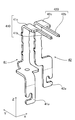
- the first terminal 41 and the second terminal 42 are made of a predetermined metal material, and are formed in an approximately L shape when viewed from the X direction as shown in FIG. Both the first terminal 41 and the second terminal 42 are insert-molded in the frame body 10. Thereby, a part of the first terminal 41 and the second terminal 42 is covered with the flange portion 11 and the connector cover portion 13. In FIG. 4, the boundary between the portion covered with the resin and the portion not covered in the first and second terminals 41 and 42 is indicated by a dotted line.
- the first terminal 41 has one end portion (the end portion on the ⁇ Z direction side) as a connection portion 41a connected to the tip portion 31a of the first electric cord 31 on the lower surface 11b side of the flange portion 11, and the other end portion is a flange portion. It reaches the upper surface 11a side of the part 11 and is configured as an external connection part 41b that can be connected to the external device.
- the second terminal 42 has one end portion (end portion on the ⁇ Z direction side) as a connection portion 42 a that is connected to the tip end portion 32 a of the second electric cord 32 on the lower surface 11 b side of the flange portion 11. The portion reaches the upper surface 11a side of the flange portion 11, and is configured as an external connection portion 42b that can be connected to the external device.
- a part of the portion of the first terminal 41 located on the upper surface 11a side of the flange portion 11 is a first extending portion 410 extending in the Y-axis direction.
- a part of the second terminal 42 located on the upper surface 11a side of the flange portion 11 is a second extending portion 420 extending in the Y-axis direction.
- the first extending portion 410 and the second extending portion 420 are adjacent to each other in a direction (that is, the X direction) orthogonal to the direction in which both extend.
- the first extending portion 410 includes an external connection portion 41b (first rod-like portion) of the first terminal 41 and a plate-like first plate-like portion 41c connected to the external connection portion 41b.
- the 2nd extension part 420 consists of the external connection part 42b (2nd rod-shaped part) of the 2nd terminal 42, and the plate-shaped 2nd plate-shaped part 42c connected with the external connection part 42b.
- the width of the first plate-like portion 41c is wider than the width of the external connection portion 41b (first rod-like portion), and the second plate-like portion.
- the width of 42c (the width in the X direction) is wider than the width of the external connection portion 42b (second rod-shaped portion).
- the first plate-like portion 41c protrudes in the direction away from the second extending portion 420 (that is, the ⁇ X direction) from the external connection portion 41b (first rod-like portion)
- the plate-like portion 42c protrudes in a direction away from the first extending portion 410 (that is, the X direction) from the external connection portion 42b (second rod-like portion).
- the first and second terminals 41 and 42 are insert-molded into the frame 10, pressure is applied to the first and second terminals 41 and 42 due to the flow of the resin, and the first and second terminals 41 and 42 are applied. There was a risk that the shape may be deformed (for example, pressure in the ⁇ Z direction is applied, and the first extension portion 410 and the second extension portion 420 of the first and second terminals 41 and 42 bow in the ⁇ Z direction. ) However, in the liquid level detection device 1 according to the present embodiment, the first and second plate-like portions 41c and 42c, which are portions covered with the resin, are formed wide as described above to ensure strength. Therefore, this can be reduced or eliminated.
- the first and second plate-like portions 41c and 42c are formed in a shape that protrudes in a direction away from each other (that is, protrudes outward). This can be reduced or eliminated. That is, in order to ensure the strength of the first and second terminals 41 and 42 and to reduce the size of the connector unit 50, the liquid level detection device 1 according to the present embodiment has the first extending portion 410 of the first terminal 41. And the second extending portion 420 of the second terminal 42 are shaped as described above.
- the liquid level detection apparatus 1 includes a rotary unit 21 that is connected to a float 21a floating on the liquid level via an arm 21b and rotates around a predetermined rotation axis R as the float 21a is displaced.
- the detecting unit 20 that detects the position of the liquid surface based on the rotation of the rotating unit 21, and one surface is the mounting surface 12a to which the detecting unit 20 is mounted, and the other surface is opposite to the mounting surface 12a.
- Plate-like mounting plate portion 12 that is the back surface 12b on the side, and a plate-shaped flange portion that protrudes from one end of the mounting plate portion 12 in a direction orthogonal to the mounting surface 12a and the back surface 12b and is attached to the tank that stores the liquid 11, the first and second electric cords 31 and 32 drawn from the detection unit 20 toward the flange unit 11, and one end portion of the flange unit 11 on the detection unit 20 side.
- the connecting portion 41a is connected to the tip portion 31a of the first electric cord 31, and the other end reaches the upper surface 11a side, which is the surface opposite to the lower surface 11b of the flange portion 11, and is connected to a predetermined external device.
- the first terminal 41 which is a connectable external connection part 41b, and a connection part 42a, one end part of which is connected to the front end part 32a of the second electric cord 32 on the lower surface 11b side of the flange part 11, and the other end part is a flange.
- a second terminal 42 that is an external connection portion 42b that reaches the upper surface 11a side of the portion 11 and can be connected to the external device, and the mounting plate portion 12 includes a gap between the detection portion 20 and the flange portion 11.
- the second electrical cord 32 passes from the mounting surface 12a side to the back surface 12b side of the mounting plate portion 12 by passing through the branching portion 122.
- connection portion 41a of the first terminal 41 is located on the attachment surface 12a side of the attachment plate portion 12
- connection portion 42a of the second terminal 42 is the attachment plate portion 12.
- the connection part 41a of the first terminal 41 and the tip part 31a of the first electric cord 31 are connected on the attachment surface 12a side of the attachment plate part 12 and are connected to the connection part 42a of the second terminal 42.
- tip part 32a of the 2nd electric cord 32 are connected by the back surface 12b side of the attachment board part 12. As shown in FIG. Thereby, as mentioned above, it can reduce or eliminate that the 1st electric cord 31 pulled out from detection part 20 and the 2nd electric cord 32 contact.
- the liquid level detection apparatus 1 is located in the attachment surface 12a side of the attachment plate part 12, and suppresses a part of 1st electric cord 31 so that the 1st electric cord 31 may not move substantially in the direction which faces the attachment surface 12a.
- the first restraining portion 111 and the second restraining portion that is located on the back surface 12b side of the mounting plate portion 12 and restrains a part of the second electrical cord 32 so that the second electrical cord 32 does not substantially move in the direction toward the back surface 12b.
- the first restraining portion 111 is provided on the lower surface 11b of the flange portion 11, and the second restraining portion 112 is provided on the lower surface 11b of the flange portion 11.
- the first restraining portion 111 is closer to the lower surface 11b of the flange portion 11 than the connection portion 41a of the first terminal 41, and the first electric cord 31 is drawn from the detection portion 20 toward the flange portion 11, and the first terminal 41, the front end portion 31a faces the detection unit 20 side so as to be folded back at a position closer to the lower surface 11b of the flange portion 11 than the connection portion 41a of 41, and the second restraining portion 112 is a connection portion of the second terminal 42.
- the upper surface 11a of the flange portion 11 is provided with a connector cover portion 13 through which the external connection portions 41b and 42b of the first and second terminals 41 and 42 can be seen to the outside.
- the external connection portions 41b and 42b of the terminals 41 and 42 constitute a connector portion 50 that can be connected to the external device, and the flange portion 11 and the connector cover portion 13 are integrally formed of a predetermined resin,
- a part of the first terminal 41 located on the upper surface 11 a side of the flange portion 11 is a first extending portion 410 extending in parallel with the upper surface 11 a of the flange portion 11.
- a part of the portion located on the upper surface 11 a side of the portion 11 extends in parallel with the first extending portion 410 and becomes a second extending portion 420 adjacent to the first extending portion 410, and the first terminal 41.
- External connection 41b is a rod-shaped first rod-shaped portion
- the first extending portion 410 is composed of the first rod-shaped portion and a plate-shaped first plate-shaped portion 41c connected to the first rod-shaped portion
- the external connection portion 42b of the second terminal 42 is a rod-shaped second rod-shaped portion
- the second extending portion 420 is a plate-shaped second plate connected to the second rod-shaped portion and the second rod-shaped portion.
- the first plate-like portion 41c is in a direction perpendicular to the direction in which the first extending portion 410 extends and away from the second extending portion 420, than the first rod-like portion.
- the width of the first plate-like portion 41c is wider than the width of the first rod-like portion
- the second plate-like portion 42c is in a direction orthogonal to the direction in which the second extending portion 420 extends. Then, the second plate-shaped portion is protruded in the direction away from the first extending portion 410 from the second rod-shaped portion.
- first terminal 41 and the second terminal 42 may be connected to an external device without providing the connector cover portion 13 on the frame 10 and without forming the connector portion 50 (direct coupler portion).
- first and second plate-like portions 41c and 42c having a wider width as described above may be bent in the Z direction to increase the strength of the terminal. Even in this case, in a broad sense, it can be said that the width of the first plate-like portion 41c is wider than the width of the first rod-like portion 41b, and the width of the second plate-like portion 42c is wider than the width of the second rod-like portion 42b. .
- the detection part 20 is attached from the back surface 12b side by providing the regulation part 120a which consists of a convex part in the back surface 12b of the attachment plate part 12 corresponding to the location covered with the detection part 20 of the attachment plate part 12. You may regulate so that it may not be.
- the restricting portion 120a formed on the mounting surface 12a side may be a concave portion instead of the convex portion. In this case, by forming a convex portion corresponding to the concave shape on the back surface of the case body 22 of the detection portion 20, the detection portion 20 is attached from the attachment surface 12a side of the attachment plate portion 12, but from the back surface 12b side. Should not be attached.
- the detection unit 20 is a sliding resistance type.
- the detection unit 20 is accompanied by rotation of a magnet provided in the rotation unit 21 by a magnetoelectric conversion element such as a Hall element.
- the liquid level may be detected by detecting a change in magnetism.
- the present invention can be applied to a liquid level detection device that detects the position (liquid level) of various liquids (fuel, etc.) in a tank provided in a vehicle (automobile, etc.).
Landscapes
- Physics & Mathematics (AREA)
- Fluid Mechanics (AREA)
- General Physics & Mathematics (AREA)
- Level Indicators Using A Float (AREA)
- Measurement Of Levels Of Liquids Or Fluent Solid Materials (AREA)
Description
本発明は、液面検出装置に関する。
例えば、乗り物(自動車等)が備えるタンク内の各種液体(燃料等)の液面の位置(液位)を検出する液面検出装置として、特許文献1に開示されたものがある。
特許文献1に開示された液面検出装置(同文献における液体遮断弁装置1)は、タンクに液面検出装置を固定するためのフランジ部と、このフランジ部から垂れ下がるように形成された取付プレートに取付けられ、タンクに収容された液体の液位を検出する検出部(ゲージユニット21)と、を備え、検出部から引き出された2つの電気コード(リード線25a,25b)が、共に、取付プレートの片面側において、フランジ部側へ向けて引き回された構成となっている(同文献の図2(b)参照)。
特許文献1に係る液面検出装置のように、複数の電気コードが取付プレートの片面側に位置する構成では、振動(例えば、車両等の乗り物から伝達される振動)によって、電気コード同士が接触して擦れ合うことで、電気コードの被覆が摩耗するおそれがある。電気コードの被覆が摩耗すると、芯線が露出する可能性がないとは言えない。芯線同士が接触すると短絡(ショート)が発生するため、フェールセーフの観点から改良の余地があった。
本発明は上記実状に鑑みてなされたものであり、検出部から引き出された複数の電気コード同士が接触することを低減する又は無くすことが可能な構成の液面検出装置を提供することを目的とする。
上記目的を達成するため、本発明に係る液面検出装置は、
液体の液面に浮くフロートとアームを介して接続され、前記フロートの変位に伴い所定の回転軸周りで回転する回転部を有し、前記回転部の回転に基づいて前記液面の位置を検出する検出部と、
一方の面が前記検出部が取り付けられている取付面であり、他方の面が前記取付面とは反対側の裏面である板状の取付板部と、前記取付板部の一端から前記取付面及び前記裏面と直交する方向に迫り出し、前記液体を収容するタンクに取り付けられる板状のフランジ部と、を有する枠体と、
前記検出部から前記フランジ部に向かって引き出された第1及び第2電気コードと、
一端部が前記フランジ部の前記検出部側の面である下面側で前記第1電気コードの先端部と接続される接続部であり、他端部が前記フランジ部の前記下面とは反対側の面である上面側に到っており所定の外部機器と接続可能な外部接続部である第1端子と、
一端部が前記フランジ部の前記下面側で前記第2電気コードの先端部と接続される接続部であり、他端部が前記フランジ部の前記上面側に到っており前記外部機器と接続可能な外部接続部である第2端子と、を備え、
前記取付板部には、前記検出部と前記フランジ部との間に貫通孔又は切り欠きからなる分岐部が設けられ、
前記第2電気コードは、前記分岐部を通過していることで、前記取付板部の前記取付面側から前記裏面側に回りこんでおり、前記第2電気コードの先端部が前記取付板部の前記裏面側に位置し、
前記第1端子の前記接続部は、前記取付板部の前記取付面側に位置し、
前記第2端子の前記接続部は、前記取付板部の前記裏面側に位置し、
前記第1端子の前記接続部と前記第1電気コードの先端部とは、前記取付板部の前記取付面側で接続され、
前記第2端子の前記接続部と前記第2電気コードの先端部とは、前記取付板部の前記裏面側で接続されている、
ことを特徴とする。
液体の液面に浮くフロートとアームを介して接続され、前記フロートの変位に伴い所定の回転軸周りで回転する回転部を有し、前記回転部の回転に基づいて前記液面の位置を検出する検出部と、
一方の面が前記検出部が取り付けられている取付面であり、他方の面が前記取付面とは反対側の裏面である板状の取付板部と、前記取付板部の一端から前記取付面及び前記裏面と直交する方向に迫り出し、前記液体を収容するタンクに取り付けられる板状のフランジ部と、を有する枠体と、
前記検出部から前記フランジ部に向かって引き出された第1及び第2電気コードと、
一端部が前記フランジ部の前記検出部側の面である下面側で前記第1電気コードの先端部と接続される接続部であり、他端部が前記フランジ部の前記下面とは反対側の面である上面側に到っており所定の外部機器と接続可能な外部接続部である第1端子と、
一端部が前記フランジ部の前記下面側で前記第2電気コードの先端部と接続される接続部であり、他端部が前記フランジ部の前記上面側に到っており前記外部機器と接続可能な外部接続部である第2端子と、を備え、
前記取付板部には、前記検出部と前記フランジ部との間に貫通孔又は切り欠きからなる分岐部が設けられ、
前記第2電気コードは、前記分岐部を通過していることで、前記取付板部の前記取付面側から前記裏面側に回りこんでおり、前記第2電気コードの先端部が前記取付板部の前記裏面側に位置し、
前記第1端子の前記接続部は、前記取付板部の前記取付面側に位置し、
前記第2端子の前記接続部は、前記取付板部の前記裏面側に位置し、
前記第1端子の前記接続部と前記第1電気コードの先端部とは、前記取付板部の前記取付面側で接続され、
前記第2端子の前記接続部と前記第2電気コードの先端部とは、前記取付板部の前記裏面側で接続されている、
ことを特徴とする。
本発明によれば、検出部から引き出された複数の電気コード同士が接触することを低減する又は無くすことができる。
本発明の一実施形態に係る液面検出装置を図面を参照して説明する。
液面検出装置1は、例えば、乗り物(自動車等)が備えるタンク内の各種液体(燃料等)の液面の位置(液位)を検出するものであり、図1~図4に示すように、枠体10と、検出部20と、第1電気コード31と、第2電気コード32と、第1端子41と、第2端子42と、を備える。
なお、図1は、第1及び第2電気コード31,32を省略して描いたものである。
なお、図1は、第1及び第2電気コード31,32を省略して描いたものである。
以下では、液面検出装置1の構成の理解を容易にするため、適宜、図1等に示す、互いに直交するX、Y、Z軸を用いて説明する。また、X、Y、Zの軸方向を示す矢印の向く方向を、各々の軸方向の+(プラス)側とし、その反対側の方向を各々の軸方向の-(マイナス)側とする。
枠体10は、所定の樹脂(例えば、ポリアセタール(POM)樹脂)からなり、主に図2(a)に示すように、フランジ部11と、取付板部12と、コネクタカバー部13と、が一体的に形成されていることで構成されている。
フランジ部11は、取付板部12の一端(+Z方向側の端)から迫り出し、燃料タンク等の液体を収容するタンク(図示せず)に取り付けられる部分である。フランジ部11は、X-Y平面と平行な面方向に広がる平板形状をなしている。このフランジ部11がビス等の固定手段によってタンクに固定されることで、液面検出装置1は、タンクに取り付けられる。液面検出装置1がタンクに取り付けられた状態では、フランジ部11より下側(-Z方向側)の部分がタンク内に位置する。具体的には、図2(b)に示すように、フランジ部11は、その上面11a(+Z方向に向く面)に配設された補強板2とともに、パッキン3を介して、タンクに取り付けられる。
補強板2は、鉄系材料等からなり、フランジ部11を上面11aから覆う。パッキン3は、ニトリルゴム(NBR)等のゴム材料からなり、フランジ部11の下面11b(-Z方向に向く面)に配設されている。
フランジ部11の下面11bには、第1電気コード31の一部を固定する第1抑え部111と、第2電気コード32の一部を固定する第2抑え部112と、が形成されている。
第1、第2抑え部111,112は、凹型形状をなしており、その凹み部内で、第1、第2電気コード31,32が特にX方向に略動かないように第1、第2電気コード31,32の一部を抑えるものである。これにより、第1、第2電気コード31,32と取付板部12とが振動等によって擦れ合いにくくなるため、第1、第2電気コード31,32が断線するリスクを低減することができる。また、第1、第2抑え部111,112の凹み部分は、第1、第2電気コード31,32の径よりも若干大きくなっており、第1、第2電気コード31,32の配設が容易になっている。第1抑え部111は、取付板部12の後述する取付面12a側に位置し、第2抑え部112は、取付板部12の後述する裏面12b側に位置する。
取付板部12は、検出部20が取り付けられる部分である。取付板部12は、フランジ部11の下面11b側に設けられ、下面11bと直交する方向に延びている。取付板部12は、Y-Z平面と平行な面方向に広がる略平板形状をなしている。
取付板部12の-X方向に向く面は、検出部20が取付けられる取付面12aとして構成されている。取付板部12の+X方向に向く面は、取付面12aの裏面12bとなる。取付板部12の取付面12aには、検出部20が裏面12b側から取り付けられないように規制する凸部からなる規制部120a(図2(a)、図6等参照)が形成されている。この機能については、後に述べる。
取付板部12のY方向両端には、取付面12a及び裏面12bの法線方向に立つ壁部121a,121bが取付板部12と一体に形成されている。つまり、壁部121a,121bは、Z-X平面方向に沿って立っており、略平板状の取付板部12の補強がなされるように形成されている。
取付板部12には、検出部20とフランジ部11との間に、取付板部12をX方向に貫通する孔からなる分岐部122が設けられている。この機能については、後に述べる。
コネクタカバー部13は、フランジ部11の上面11a側に設けられ、第1及び第2端子41,42の一部を外部に覗かせる。この第1及び第2端子41,42の一部(後述する外部接続部41b,42b)とコネクタカバー部13によりコネクタ部50(ダイレクトカプラ部)が構成される。このコネクタ部50は、所定の外部機器の端子に接続可能であり、これにより、検出部20の検出信号を接続された外部機器に供給することができる。検出信号を取得した外部機器は、取得した検出信号に基づいてタンク内の液体残量値(例えば、残燃料値)を得る。コネクタカバー部13の開口部130は、フランジ部11の上面11aと平行な方向に向かって開口している。
検出部20は、回転部21と、回転部21を回転可能に保持するケース体22と、を備える。回転部21とケース体22とは、所定の樹脂から形成されている。
回転部21は、所定の樹脂からなる略円筒形の部材であり、図1に示すように、前記タンクに収容された液体の液面に浮くフロート21aと、アーム21bを介して接続される。回転部21は、フロート21aの変位に伴い、X軸と平行な回転軸R周りで回転する。
フロート21aは、合成樹脂、金属材料等から略俵型に形成された浮きである。フロート21aは、前記タンク内の液体から浮力を受けて液面に浮き、液面の変動に伴って変位する。
アーム21bは、金属からなる棒であり、その一端部にはフロート21aが取り付けられる。アーム21bの他端部は、回転部21に保持される。
ケース体22は、所定の樹脂からなり、回転部21を回転可能に保持する。また、ケース体22は、取付板部12に、取付面12a側から固定されている。具体的には、ケース体22には爪部C1,C2,C3が形成されており(図3(b)参照)、これらの爪部が取付板部12に設けられた取付孔H1,H2,H3と係合することにより、ケース体22は、取付板部12に固定されている。このようにして、検出部20は、取付板部12の取付面12a側に取り付けられている。
ここで、検出部20は、前述した規制部120aにより、取付板部12の裏面12b側からは取り付けられないようになっている。
具体的には、取付板部12の取付面12a側であって、取付板部12の図2(a)における左右端部に位置する取付孔H1、H2各々の近傍に、凸部からなる規制部120aが形成されていることで、仮に、裏面12b側から検出部20を取り付けようとして、爪部C1,C2,C3を取付孔H1,H2,H3に係合させようとしても、爪部C1,C2は、規制部120aがあるため、取付孔H1,H2と係合しないようになっている。つまり、規制部120aは、爪部C1,C2と取付孔H1,H2とが完全には係合しない程度の高さ(X方向の高さ)を有する凸部として形成されている。このように凸部からなる規制部120aを設けただけで、組み付け時において、検出部20が取付板部12の裏面12b側から取り付けられることを防止できるため、簡単な構成で誤組みを防止できる。なお、規制部120aは、取付孔H1,H2,H3のいずれか1つの近傍に1つだけ設けてもよいし、すべての近傍に(つまり、3つ)設けてもよい。
具体的には、取付板部12の取付面12a側であって、取付板部12の図2(a)における左右端部に位置する取付孔H1、H2各々の近傍に、凸部からなる規制部120aが形成されていることで、仮に、裏面12b側から検出部20を取り付けようとして、爪部C1,C2,C3を取付孔H1,H2,H3に係合させようとしても、爪部C1,C2は、規制部120aがあるため、取付孔H1,H2と係合しないようになっている。つまり、規制部120aは、爪部C1,C2と取付孔H1,H2とが完全には係合しない程度の高さ(X方向の高さ)を有する凸部として形成されている。このように凸部からなる規制部120aを設けただけで、組み付け時において、検出部20が取付板部12の裏面12b側から取り付けられることを防止できるため、簡単な構成で誤組みを防止できる。なお、規制部120aは、取付孔H1,H2,H3のいずれか1つの近傍に1つだけ設けてもよいし、すべての近傍に(つまり、3つ)設けてもよい。
ケース体22内部には、複数の電極と、これら複数の電極と接続する抵抗体と、が形成された図示しない回路基板(プリント回路板)が設けられている。回転部21裏側には、金属からなる接点(図示せず)が設けられており、この接点が、前記回路基板に形成された複数の電極のいずれかと接触すると、接触した電極に対応した抵抗体の抵抗値が検出部20から検出信号として出力される。このように、検出部20は、フロート21aに接続されたアーム21bの動作に基づいて接点を抵抗上で摺動させる摺動抵抗式の検出部として構成されている。
第1及び第2電気コード31,32は、前記回路基板と導通接続されており、検出部20からフランジ部11に向かって(つまり、+Z方向に)引き出されている。具体的には、第1電気コード31は、GND(グランド)ラインとして構成され、第2電気コード32は、前記検出信号を出力するための信号ラインとして構成されている。なお、第1電気コード31が信号ラインとして構成され、第2電気コード32がGNDラインとして構成されてもよい。
第1電気コード31は、検出部20からフランジ部11に向かって引き出され、途中で折り返すようにして、その先端部31aが検出部20側に向いている。先端部31aは、被覆がなく、芯線が露出している部分であり、第1端子41(第1端子41の後述する接続部41a)と半田付けにより接続される部分である。
具体的には、図3(a)に示すように、第1電気コード31は、検出部20側から、壁部121aに沿うように+Z方向に延び、第1端子41の後述する接続部41aよりもフランジ部11の下面11bに近い位置で折り返えすようにして、先端部31aが概ね-Z方向に向いている。これにより、第1電気コード31は、図3(a)に示すように、鉤爪状に撓んでいる。第1電気コード31は、その全てが、取付板部12の取付面12a側に位置する。
具体的には、図3(a)に示すように、第1電気コード31は、検出部20側から、壁部121aに沿うように+Z方向に延び、第1端子41の後述する接続部41aよりもフランジ部11の下面11bに近い位置で折り返えすようにして、先端部31aが概ね-Z方向に向いている。これにより、第1電気コード31は、図3(a)に示すように、鉤爪状に撓んでいる。第1電気コード31は、その全てが、取付板部12の取付面12a側に位置する。
ここで、第1抑え部111は、第1端子41の後述する接続部41aよりも、フランジ部11の下面11bに近くに位置し、第1電気コード31の折り返し部分近傍を抑えている。これにより、第1電気コード31と第1端子41とを半田付けにより接続する作業時において、第1電気コード31の折り返し部分から先端部31aの向きが定めやすくなり、半田付けを容易に行うことができる。さらには、第1電気コード31は、その折り返し部分近傍が、第1抑え部111に抑えられているため、特に、第1端子41との接続箇所近傍(つまり、接続部41a近傍)が振動等により動きづらい。そのため、第1電気コード31と第1端子41との半田付け箇所にかかる負荷が軽減される。本実施形態に係る液面検出装置1では、このような構造により、第1電気コード31と第1端子41との電気的接続の信頼性を確保している。
なお、第1抑え部111が、第1端子41の後述する接続部41aよりも、フランジ部11の下面11bに近くに位置するとは、一例として、図3(a)に示すように、下面11bと第1抑え部111の下端(-Z方向の端)との距離D1が、下面11bと第1端子41の接続部41aの下端との距離D2よりも小さいことを指す。また、壁部121aは、第1電気コード31が+Y方向側に移動しないように、抑制する機能も有している。
第2電気コード32は、検出部20からフランジ部11に向かって引き出され、途中で折り返すようにして、その先端部32aが検出部20側に向いている。先端部32aは、被覆がなく、芯線が露出している部分であり、第2端子42(第2端子42の後述する接続部42a)と半田付けにより接続される部分である。
具体的には、図3(a)、(b)に示すように、第2電気コード32は、検出部20からフランジ部11に向かって引き出され、貫通孔からなる分岐部122を通過し、取付板部12の裏面12b側に到る。第2電気コード32のうち、分岐部122から裏面12b側に出た部分は、壁部121bに沿うようにしてフランジ部11方向に延び、第2端子42の後述する接続部42aよりもフランジ部11の下面11bに近い位置で折り返すようにして、先端部32aが概ね-Z方向に向いている。これにより、第2電気コード32は、図3(b)に示すように、鉤爪状に撓んでいる。第2電気コード32は、検出部20から分岐部122を通過する前の部分が取付板部12の取付面12a側に位置し、分岐部122を通過した後の部分が裏面12b側に位置する。
具体的には、図3(a)、(b)に示すように、第2電気コード32は、検出部20からフランジ部11に向かって引き出され、貫通孔からなる分岐部122を通過し、取付板部12の裏面12b側に到る。第2電気コード32のうち、分岐部122から裏面12b側に出た部分は、壁部121bに沿うようにしてフランジ部11方向に延び、第2端子42の後述する接続部42aよりもフランジ部11の下面11bに近い位置で折り返すようにして、先端部32aが概ね-Z方向に向いている。これにより、第2電気コード32は、図3(b)に示すように、鉤爪状に撓んでいる。第2電気コード32は、検出部20から分岐部122を通過する前の部分が取付板部12の取付面12a側に位置し、分岐部122を通過した後の部分が裏面12b側に位置する。
ここで、第2抑え部112は、第2端子42の後述する接続部42aよりも、フランジ部11の下面11bに近くに位置し、第2電気コード32の折り返し部分近傍を抑えている。これにより、第1電気コード31の説明と同様に、第2電気コード32においても半田付けが容易であり、また、第2電気コード32と第2端子42との半田付け箇所にかかる負荷が軽減される。本実施形態に係る液面検出装置1では、このような構造により、第2電気コード32と第2端子42との電気的接続の信頼性を確保している。
なお、第2抑え部112が、第2端子42の後述する接続部42aよりも、フランジ部11の下面11bに近くに位置するとは、前述した第1抑え部111での説明と同様である。また、壁部121bは、第2電気コード32が-Y方向側に移動しないように、抑制する機能も有している。
以上のように、第1電気コード31と第2電気コード32との関係は、第1電気コード31は、その全てが取付板部12の取付面12a側に位置する一方、第2電気コード32は、分岐部122を通過していることで、取付板部12の取付面12a側から裏面12b側に回りこんでおり、第2電気コード32の先端部32aが取付板部12の裏面b側に位置している。液面検出装置1では、このような関係で第1電気コード31と第2電気コード32とを配設したことから、検出部20から引き出された第1、第2電気コード31、32同士が接触することを低減する又は無くすことができる。
第1端子41、第2端子42は、所定の金属材料からなり、図4に示すように、X方向から見て、略L字状に形成されている。第1端子41及び第2端子42は、共に、枠体10にインサート成形されている。これにより、第1端子41及び第2端子42の一部は、フランジ部11とコネクタカバー部13に接触して覆われている。なお、図4に、第1及び第2端子41、42における、樹脂に接触して覆われている部分と覆われていない部分との境界を点線で示した。
第1端子41は、その一端部(-Z方向側の端部)がフランジ部11の下面11b側で第1電気コード31の先端部31aと接続される接続部41aとして、その他端部がフランジ部11の上面11a側に到っており前記外部機器と接続可能な外部接続部41bとして構成されている。同様に、第2端子42は、その一端部(-Z方向側の端部)がフランジ部11の下面11b側で第2電気コード32の先端部32aと接続される接続部42aとして、その他端部がフランジ部11の上面11a側に到っており前記外部機器と接続可能な外部接続部42bとして構成されている。
図4、図5(b)等に示すように、第1端子41の接続部41aは、鉤爪状となっており、第1電気コード31の先端部31aと半田付けにより接続される。同様に、第2端子42の接続部42aは、鉤爪状となっており、第2電気コード32の先端部32aと半田付けにより接続される。
図5(a)に示すように、第1端子41の外部接続部41bは、先端が-Y方向に向く棒形状であり、コネクタカバー部13から外部を覗く。以下、外部接続部41bを「第1棒状部」とも言う。同様に、第2端子42の外部接続部42bは、先端が-Y方向に向く棒形状であり、コネクタカバー部13から外部を覗く。以下、外部接続部42bを「第2棒状部」とも言う。
外部接続部41bと外部接続部42bとコネクタカバー部13とにより前述したコネクタ部50が構成されている。
外部接続部41bと外部接続部42bとコネクタカバー部13とにより前述したコネクタ部50が構成されている。
図4、図5(a)に示すように、第1端子41のうちフランジ部11の上面11a側に位置する部分の一部は、Y軸方向に延びる第1延在部410となっている。同様に、第2端子42のうちフランジ部11の上面11a側に位置する部分の一部は、Y軸方向に延びる第2延在部420となっている。第1延在部410と第2延在部420とは、両者が延びる方向と直交する方向(つまり、X方向)において互いに隣り合っている。
第1延在部410は、第1端子41の外部接続部41b(第1棒状部)と、外部接続部41bと繋がる板状の第1板状部41cと、からなる。同様に、第2延在部420は、第2端子42の外部接続部42b(第2棒状部)と、外部接続部42bと繋がる板状の第2板状部42cと、からなる。
図4、図5(a)からわかるように、第1板状部41cの幅(X方向の幅)は、外部接続部41b(第1棒状部)の幅よりも広く、第2板状部42cの幅(X方向の幅)は、外部接続部42b(第2棒状部)の幅よりも広くなっている。具体的には、第1板状部41cは、第2延在部420から離れる方向(つまり、-X方向)に、外部接続部41b(第1棒状部)よりも迫り出しており、第2板状部42cは、第1延在部410から離れる方向(つまり、X方向)に、外部接続部42b(第2棒状部)よりも迫り出している。
第1端子41の第1延在部410と、第2端子42の第2延在部420とをこのようにした理由を以下に説明する。
第1端子41の第1延在部410と、第2端子42の第2延在部420とをこのようにした理由を以下に説明する。
(1)第1及び第2端子41,42を枠体10にインサート成形する際に、樹脂の流動により第1及び第2端子41,42に圧力がかかり、第1及び第2端子41,42形状が変形するおそれがあった(例えば、-Z方向の圧力がかかり、第1及び第2端子41,42の第1延在部410と第2延在部420とが、-Z方向におじぎをしてしまう)。しかし、本実施形態に係る液面検出装置1では、樹脂に接触して覆われる部分である第1及び第2板状部41c,42cを上記のように幅広に形成し、強度を確保しているため、このようなことを軽減または無くすことができる。
(2)上記のように第1及び第2端子41,42の強度を確保する場合、第1延在部410と第2延在部420とが近づく方向に板状部を迫り出させる(つまり、内側に迫り出させる)方法も考えられるが、これでは、外部接続部41bと42bとの間の距離を狭めることができず、コネクタ部50を小型に構成することが困難となる。これは、板状部を内側に迫り出させた形状のまま、外部接続部41bと42bとの間の距離を狭めようとすると、インサート成形の際に、第1端子41と第2端子42とが接触するおそれがあるためである。しかし、本実施形態に係る液面検出装置1では、第1及び第2板状部41c,42cを互いに離れる方向に迫り出した(つまり、外側に迫り出した)形状に形成しているため、このようなことを軽減または無くすことができる。
つまり、第1及び第2端子41,42の強度確保、及び、コネクタ部50の小型化を図るため、本実施形態に係る液面検出装置1では、第1端子41の第1延在部410と第2端子42の第2延在部420とを上記で説明したような形状にしている。
(2)上記のように第1及び第2端子41,42の強度を確保する場合、第1延在部410と第2延在部420とが近づく方向に板状部を迫り出させる(つまり、内側に迫り出させる)方法も考えられるが、これでは、外部接続部41bと42bとの間の距離を狭めることができず、コネクタ部50を小型に構成することが困難となる。これは、板状部を内側に迫り出させた形状のまま、外部接続部41bと42bとの間の距離を狭めようとすると、インサート成形の際に、第1端子41と第2端子42とが接触するおそれがあるためである。しかし、本実施形態に係る液面検出装置1では、第1及び第2板状部41c,42cを互いに離れる方向に迫り出した(つまり、外側に迫り出した)形状に形成しているため、このようなことを軽減または無くすことができる。
つまり、第1及び第2端子41,42の強度確保、及び、コネクタ部50の小型化を図るため、本実施形態に係る液面検出装置1では、第1端子41の第1延在部410と第2端子42の第2延在部420とを上記で説明したような形状にしている。
本実施形態に係る液面検出装置1は、液体の液面に浮くフロート21aとアーム21bを介して接続され、フロート21aの変位に伴い所定の回転軸R周りで回転する回転部21を有し、回転部21の回転に基づいて前記液面の位置を検出する検出部20と、一方の面が検出部20が取り付けられている取付面12aであり、他方の面が取付面12aとは反対側の裏面12bである板状の取付板部12と、取付板部12の一端から取付面12a及び裏面12bと直交する方向に迫り出し、前記液体を収容するタンクに取り付けられる板状のフランジ部11と、を有する枠体10と、検出部20からフランジ部11に向かって引き出された第1及び第2電気コード31,32と、一端部がフランジ部11の検出部20側の面である下面11b側で第1電気コード31の先端部31aと接続される接続部41aであり、他端部がフランジ部11の下面11bとは反対側の面である上面11a側に到っており所定の外部機器と接続可能な外部接続部41bである第1端子41と、一端部がフランジ部11の下面11b側で第2電気コード32の先端部32aと接続される接続部42aであり、他端部がフランジ部11の上面11a側に到っており前記外部機器と接続可能な外部接続部42bである第2端子42と、を備え、取付板部12には、検出部20とフランジ部11との間に貫通孔からなる分岐部122が設けられ、第2電気コード32は、分岐部122を通過していることで、取付板部12の取付面12a側から裏面12b側に回りこんでおり、第2電気コード32の先端部32aが取付板部12の裏面12b側に位置し、第1端子41の接続部41aは、取付板部12の取付面12a側に位置し、第2端子42の接続部42aは、取付板部12の裏面12b側に位置し、第1端子41の接続部41aと第1電気コード31の先端部31aとは、取付板部12の取付面12a側で接続され、第2端子42の接続部42aと第2電気コード32の先端部32aとは、取付板部12の裏面12b側で接続されている。
これにより、前述したように、検出部20から引き出された第1電気コード31と第2電気コード32とが接触することを低減する又は無くすことができる。
これにより、前述したように、検出部20から引き出された第1電気コード31と第2電気コード32とが接触することを低減する又は無くすことができる。
また、液面検出装置1は、取付板部12の取付面12a側に位置し、第1電気コード31が取付面12aの向く方向に略動かないように第1電気コード31の一部を抑える第1抑え部111と、取付板部12の裏面12b側に位置し、第2電気コード32が裏面12bの向く方向に略動かないように第2電気コード32の一部を抑える第2抑え部112と、を備え、第1抑え部111は、フランジ部11の下面11bに設けられ、第2抑え部112は、フランジ部11の下面11bに設けられている。
これにより、前述したように、第1、第2電気コード31,32と取付板部12とが振動等によって擦れ合いにくくなるため、第1、第2電気コード31,32が断線するリスクを低減することができる。
これにより、前述したように、第1、第2電気コード31,32と取付板部12とが振動等によって擦れ合いにくくなるため、第1、第2電気コード31,32が断線するリスクを低減することができる。
第1抑え部111は、第1端子41の接続部41aよりも、フランジ部11の下面11bに近く、第1電気コード31は、検出部20からフランジ部11に向かって引き出され、第1端子41の接続部41aよりもフランジ部11の下面11bに近い位置で折り返すようにして、その先端部31aが検出部20側に向いており、第2抑え部112は、第2端子42の接続部42aよりも、フランジ部11の下面11bに近く、第2電気コード32は、検出部20からフランジ部11に向かって引き出され、第2端子42の接続部42aよりもフランジ部11の下面11bに近い位置で折り返すようにして、その先端部32aが検出部20側に向いている。
これにより、前述したように、電気コードと端子との半田付けが容易であり、また、半田付け箇所にかかる負荷が軽減される。このため、電気コードと端子との電気的接続の信頼性を確保できる。
これにより、前述したように、電気コードと端子との半田付けが容易であり、また、半田付け箇所にかかる負荷が軽減される。このため、電気コードと端子との電気的接続の信頼性を確保できる。
また、フランジ部11の上面11aには、第1及び第2端子41,42の外部接続部41b,42bを外部に覗かせるコネクタカバー部13を備え、このコネクタカバー部13と第1及び第2端子41,42の外部接続部41b,42bとで前記外部機器と接続可能なコネクタ部50が構成され、フランジ部11とコネクタカバー部13とは、所定の樹脂により一体的に形成されており、第1端子41のうちフランジ部11の上面11a側に位置する部分の一部は、フランジ部11の上面11aと平行に延びる第1延在部410となっており、第2端子42のうちフランジ部11の上面11a側に位置する部分の一部は、第1延在部410と平行に延び、第1延在部410と隣り合う第2延在部420となっており、第1端子41の外部接続部41bは、棒状の第1棒状部となっており、第1延在部410は、前記第1棒状部と、前記第1棒状部と繋がる板状の第1板状部41cと、からなり、第2端子42の外部接続部42bは、棒状の第2棒状部となっており、第2延在部420は、前記第2棒状部と、前記第2棒状部と繋がる板状の第2板状部42cと、からなり、第1板状部41cが、第1延在部410が延びる方向と直交する方向であって第2延在部420から離れる方向に、前記第1棒状部よりも迫り出していることによって、第1板状部41cの幅は、前記第1棒状部の幅よりも広く、第2板状部42cが、第2延在部420が延びる方向と直交する方向であって第1延在部410から離れる方向に、前記第2棒状部よりも迫り出していることによって、第2板状部42cの幅は、前記第2棒状部の幅よりも広く、第1及び第2板状部41c,42cの少なくとも一部は、コネクタカバー部13に接触して覆われている。
これにより、前述したように、第1及び第2端子41,42の強度確保、及び、コネクタ部50の小型化を図ることができる。
これにより、前述したように、第1及び第2端子41,42の強度確保、及び、コネクタ部50の小型化を図ることができる。
また、取付板部12には、裏面12b側から検出部20が取り付けられないように規制する規制部120aが設けられている。
これにより、前述したように、検出部20を誤って組み付けることを防止できる。
これにより、前述したように、検出部20を誤って組み付けることを防止できる。
なお、本発明は上記の実施形態及び図面によって限定されるものではない。適宜変更(構成要素の削除も含む)を加えることができるのはもちろんである。以下に、変形例の一例を記す。
(変形例)
以上の説明では、分岐部122が貫通孔である例を示したが、図7に示すような切り欠きからなる分岐部122’であってもよい。
以上の説明では、分岐部122が貫通孔である例を示したが、図7に示すような切り欠きからなる分岐部122’であってもよい。
また、図示しないが、第1抑え部111が取付板部12の取付面12aに設けられ、第2抑え部112が取付板部12の裏面12bに設けられていてもよい。
また、枠体10にコネクタカバー部13を設けず、コネクタ部50(ダイレクトカプラ部)を形成せずに、第1端子41、第2端子42を外部機器に接続させてもよい。
また、前述のように幅広にした第1及び第2板状部41c,42cを、Z方向に折り曲げ形成して、端子の強度を高めても良い。この場合においても、広義に、第1板状部41cの幅が第1棒状部41bの幅よりも広く、第2板状部42cの幅が第2棒状部42bの幅よりも広い、と言える。
また、凸部からなる規制部120aを、取付板部12の検出部20に覆われている箇所に対応する、取付板部12の裏面12bに設けることで、検出部20が裏面12b側から取り付けられないように規制してもよい。
さらには、取付面12a側に形成された規制部120aは、凸部でなく、凹部であってもよい。この場合、検出部20のケース体22の背面に、凹部形状に対応した凸部を形成することで、検出部20が取付板部12の取付面12a側からは取り付けられるが、裏面12b側からは取り付けられないようにすればよい。
さらには、取付面12a側に形成された規制部120aは、凸部でなく、凹部であってもよい。この場合、検出部20のケース体22の背面に、凹部形状に対応した凸部を形成することで、検出部20が取付板部12の取付面12a側からは取り付けられるが、裏面12b側からは取り付けられないようにすればよい。
また、以上の説明では、検出部20が摺動抵抗式のものである例を示したが、検出部20は、ホール素子等の磁電変換素子によって回転部21に設けられたマグネットの回転に伴う磁気の変化を検出することで液位を検出するものであってもよい。
以上の説明では、本発明の理解を容易にするために、重要でない公知の技術的事項の説明を適宜省略した。
本発明は、乗り物(自動車等)が備えるタンク内の各種液体(燃料等)の液面の位置(液位)を検出する液面検出装置に適用可能である。
1 液面検出装置
10 枠体
11 フランジ部
11a 上面
11b 下面
111 第1抑え部
112 第2抑え部
12 取付板部
12a 取付面
12b 裏面
120a 規制部
121a,121b 壁部
122 分岐部
13 コネクタカバー部
20 検出部
21 回転部
R 回転軸
21a フロート
21b アーム
22 ケース体
31 第1電気コード
31a 先端部
32 第2電気コード
32a 先端部
41 第1端子
410 第1延在部
41a 接続部
41b 外部接続部(第1棒状部)
41c 第1板状部
42 第2端子
420 第2延在部
42a 接続部
42b 外部接続部(第2棒状部)
42c 第2板状部
50 コネクタ部
10 枠体
11 フランジ部
11a 上面
11b 下面
111 第1抑え部
112 第2抑え部
12 取付板部
12a 取付面
12b 裏面
120a 規制部
121a,121b 壁部
122 分岐部
13 コネクタカバー部
20 検出部
21 回転部
R 回転軸
21a フロート
21b アーム
22 ケース体
31 第1電気コード
31a 先端部
32 第2電気コード
32a 先端部
41 第1端子
410 第1延在部
41a 接続部
41b 外部接続部(第1棒状部)
41c 第1板状部
42 第2端子
420 第2延在部
42a 接続部
42b 外部接続部(第2棒状部)
42c 第2板状部
50 コネクタ部
Claims (5)
- 液体の液面に浮くフロートとアームを介して接続され、前記フロートの変位に伴い所定の回転軸周りで回転する回転部を有し、前記回転部の回転に基づいて前記液面の位置を検出する検出部と、
一方の面が前記検出部が取り付けられている取付面であり、他方の面が前記取付面とは反対側の裏面である板状の取付板部と、前記取付板部の一端から前記取付面及び前記裏面と直交する方向に迫り出し、前記液体を収容するタンクに取り付けられる板状のフランジ部と、を有する枠体と、
前記検出部から前記フランジ部に向かって引き出された第1及び第2電気コードと、
一端部が前記フランジ部の前記検出部側の面である下面側で前記第1電気コードの先端部と接続される接続部であり、他端部が前記フランジ部の前記下面とは反対側の面である上面側に到っており所定の外部機器と接続可能な外部接続部である第1端子と、
一端部が前記フランジ部の前記下面側で前記第2電気コードの先端部と接続される接続部であり、他端部が前記フランジ部の前記上面側に到っており前記外部機器と接続可能な外部接続部である第2端子と、を備え、
前記取付板部には、前記検出部と前記フランジ部との間に貫通孔又は切り欠きからなる分岐部が設けられ、
前記第2電気コードは、前記分岐部を通過していることで、前記取付板部の前記取付面側から前記裏面側に回りこんでおり、前記第2電気コードの先端部が前記取付板部の前記裏面側に位置し、
前記第1端子の前記接続部は、前記取付板部の前記取付面側に位置し、
前記第2端子の前記接続部は、前記取付板部の前記裏面側に位置し、
前記第1端子の前記接続部と前記第1電気コードの先端部とは、前記取付板部の前記取付面側で接続され、
前記第2端子の前記接続部と前記第2電気コードの先端部とは、前記取付板部の前記裏面側で接続されている、
ことを特徴とする液面検出装置。 - 前記取付板部の前記取付面側に位置し、前記第1電気コードが前記取付面の向く方向に略動かないように前記第1電気コードの一部を抑える第1抑え部と、
前記取付板部の裏面側に位置し、前記第2電気コードが前記裏面の向く方向に略動かないように前記第2電気コードの一部を抑える第2抑え部と、を備え、
前記第1抑え部は、前記フランジ部の下面又は前記取付板部の前記取付面に設けられ、
前記第2抑え部は、前記フランジ部の下面又は前記取付板部の前記裏面に設けられている、
ことを特徴とする請求項1に記載の液面検出装置。 - 前記第1抑え部は、前記第1端子の前記接続部よりも、前記フランジ部の前記下面に近く、
前記第1電気コードは、前記検出部から前記フランジ部に向かって引き出され、前記第1端子の前記接続部よりも前記フランジ部の前記下面に近い位置で折り返すようにして、その先端部が前記検出部側に向いており、
前記第2抑え部は、前記第2端子の前記接続部よりも、前記フランジ部の前記下面に近く、
前記第2電気コードは、前記検出部から前記フランジ部に向かって引き出され、前記第2端子の前記接続部よりも前記フランジ部の前記下面に近い位置で折り返すようにして、その先端部が前記検出部側に向いている、
ことを特徴とする請求項2に記載の液面検出装置。 - 前記フランジ部の前記上面には、前記第1及び第2端子の前記外部接続部を外部に覗かせるコネクタカバー部を備え、このコネクタカバー部と前記第1及び第2端子の前記外部接続部とで前記外部機器と接続可能なコネクタ部が構成され、
前記フランジ部と前記コネクタカバー部とは、所定の樹脂により一体的に形成されており、
前記第1端子のうち前記フランジ部の前記上面側に位置する部分の一部は、前記フランジ部の前記上面と平行に延びる第1延在部となっており、
前記第2端子のうち前記フランジ部の前記上面側に位置する部分の一部は、前記第1延在部と平行に延び、前記第1延在部と隣り合う第2延在部となっており、
前記第1端子の前記外部接続部は、棒状の第1棒状部となっており、前記第1延在部は、前記第1棒状部と、前記第1棒状部と繋がる板状の第1板状部と、からなり、
前記第2端子の前記外部接続部は、棒状の第2棒状部となっており、前記第2延在部は、前記第2棒状部と、前記第2棒状部と繋がる板状の第2板状部と、からなり、
前記第1板状部が、前記第1延在部が延びる方向と直交する方向であって前記第2延在部から離れる方向に、前記第1棒状部よりも迫り出していることによって、前記第1板状部の幅は、前記第1棒状部の幅よりも広く、
前記第2板状部が、前記第2延在部が延びる方向と直交する方向であって前記第1延在部から離れる方向に、前記第2棒状部よりも迫り出していることによって、前記第2板状部の幅は、前記第2棒状部の幅よりも広く、
前記第1及び第2板状部の少なくとも一部は、前記コネクタカバー部に接触して覆われている、
ことを特徴とする請求項1乃至3のいずれか1項に記載の液面検出装置。 - 前記取付板部には、前記裏面側から前記検出部が取り付けられないように規制する規制部が設けられている、
ことを特徴とする請求項1乃至4のいずれか1項に記載の液面検出装置。
Priority Applications (3)
| Application Number | Priority Date | Filing Date | Title |
|---|---|---|---|
| EP13809202.8A EP2869045B1 (en) | 2012-06-28 | 2013-06-05 | Liquid level detection device |
| CN201380033215.7A CN104380062B (zh) | 2012-06-28 | 2013-06-05 | 液面检测装置 |
| US14/403,933 US9435678B2 (en) | 2012-06-28 | 2013-06-05 | Liquid level detection device |
Applications Claiming Priority (2)
| Application Number | Priority Date | Filing Date | Title |
|---|---|---|---|
| JP2012145755A JP5862481B2 (ja) | 2012-06-28 | 2012-06-28 | 液面検出装置 |
| JP2012-145755 | 2012-06-28 |
Publications (1)
| Publication Number | Publication Date |
|---|---|
| WO2014002709A1 true WO2014002709A1 (ja) | 2014-01-03 |
Family
ID=49782875
Family Applications (1)
| Application Number | Title | Priority Date | Filing Date |
|---|---|---|---|
| PCT/JP2013/065522 Ceased WO2014002709A1 (ja) | 2012-06-28 | 2013-06-05 | 液面検出装置 |
Country Status (5)
| Country | Link |
|---|---|
| US (1) | US9435678B2 (ja) |
| EP (1) | EP2869045B1 (ja) |
| JP (1) | JP5862481B2 (ja) |
| CN (1) | CN104380062B (ja) |
| WO (1) | WO2014002709A1 (ja) |
Families Citing this family (6)
| Publication number | Priority date | Publication date | Assignee | Title |
|---|---|---|---|---|
| WO2018074352A1 (ja) * | 2016-10-21 | 2018-04-26 | 日本精機株式会社 | 移動センサ用の被検出ユニットおよびこれを備えた液面検出装置 |
| US10648848B2 (en) * | 2017-06-05 | 2020-05-12 | Yazaki Corporation | Mounting structure of liquid level detecting device |
| JP6923489B2 (ja) * | 2018-07-03 | 2021-08-18 | ファナック株式会社 | 水平多関節型ロボット |
| JP6947764B2 (ja) * | 2019-02-12 | 2021-10-13 | 矢崎総業株式会社 | 液位検出装置ユニット |
| JP7367536B2 (ja) * | 2020-01-21 | 2023-10-24 | 日本精機株式会社 | 液面検出装置 |
| US20240102842A1 (en) * | 2022-09-28 | 2024-03-28 | Huan Zheng | Laser fuel measurement device |
Citations (5)
| Publication number | Priority date | Publication date | Assignee | Title |
|---|---|---|---|---|
| JPS60163318U (ja) * | 1984-04-06 | 1985-10-30 | カルソニックカンセイ株式会社 | 液面検出器 |
| JPH02189428A (ja) * | 1988-11-29 | 1990-07-25 | Stewart Warner Corp | 万能燃料計 |
| US5216919A (en) * | 1992-01-02 | 1993-06-08 | Teleflex Incorporated | Fuel level sender |
| JPH10288106A (ja) | 1997-04-10 | 1998-10-27 | Nok Corp | 液体遮断弁装置 |
| JP2004108263A (ja) * | 2002-09-19 | 2004-04-08 | Denso Corp | 燃料供給装置 |
Family Cites Families (6)
| Publication number | Priority date | Publication date | Assignee | Title |
|---|---|---|---|---|
| IT1027353B (it) * | 1975-01-24 | 1978-11-20 | Mecanique Ind Int | Dispositivo rilevatore del livel lo del fluido all interno di un serbatoio |
| JPH05240682A (ja) * | 1992-02-26 | 1993-09-17 | Nippondenso Co Ltd | 液面検出装置 |
| JP3629840B2 (ja) * | 1996-05-08 | 2005-03-16 | 株式会社デンソー | 液面検出装置の取付け構造 |
| US6209392B1 (en) * | 1998-12-31 | 2001-04-03 | Methode Electronics, Inc. | Fuel level sensor with miniaturized ceramic resistor card |
| US6837222B2 (en) * | 2002-09-19 | 2005-01-04 | Denso Corporation | Fuel supply apparatus |
| US20080053219A1 (en) * | 2006-09-06 | 2008-03-06 | Ireland Hugh W | Multifunction fuel sensor |
-
2012
- 2012-06-28 JP JP2012145755A patent/JP5862481B2/ja not_active Expired - Fee Related
-
2013
- 2013-06-05 US US14/403,933 patent/US9435678B2/en not_active Expired - Fee Related
- 2013-06-05 EP EP13809202.8A patent/EP2869045B1/en active Active
- 2013-06-05 WO PCT/JP2013/065522 patent/WO2014002709A1/ja not_active Ceased
- 2013-06-05 CN CN201380033215.7A patent/CN104380062B/zh not_active Expired - Fee Related
Patent Citations (5)
| Publication number | Priority date | Publication date | Assignee | Title |
|---|---|---|---|---|
| JPS60163318U (ja) * | 1984-04-06 | 1985-10-30 | カルソニックカンセイ株式会社 | 液面検出器 |
| JPH02189428A (ja) * | 1988-11-29 | 1990-07-25 | Stewart Warner Corp | 万能燃料計 |
| US5216919A (en) * | 1992-01-02 | 1993-06-08 | Teleflex Incorporated | Fuel level sender |
| JPH10288106A (ja) | 1997-04-10 | 1998-10-27 | Nok Corp | 液体遮断弁装置 |
| JP2004108263A (ja) * | 2002-09-19 | 2004-04-08 | Denso Corp | 燃料供給装置 |
Non-Patent Citations (1)
| Title |
|---|
| See also references of EP2869045A4 |
Also Published As
| Publication number | Publication date |
|---|---|
| JP5862481B2 (ja) | 2016-02-16 |
| CN104380062A (zh) | 2015-02-25 |
| US20150185066A1 (en) | 2015-07-02 |
| EP2869045A1 (en) | 2015-05-06 |
| CN104380062B (zh) | 2017-07-04 |
| EP2869045A4 (en) | 2016-02-17 |
| EP2869045B1 (en) | 2017-03-29 |
| JP2014010008A (ja) | 2014-01-20 |
| US9435678B2 (en) | 2016-09-06 |
Similar Documents
| Publication | Publication Date | Title |
|---|---|---|
| JP5862481B2 (ja) | 液面検出装置 | |
| US9677926B2 (en) | Liquid-level detection device | |
| JP5825520B2 (ja) | 液面検出装置 | |
| JP5232047B2 (ja) | コンデンサの取り付け構造 | |
| WO2014132962A1 (ja) | 液面レベルセンサ | |
| JP5047919B2 (ja) | 電流センサ | |
| CN102639976A (zh) | 液面检测装置 | |
| JP6679539B2 (ja) | 液位検出装置 | |
| JP4093126B2 (ja) | 液面検出装置 | |
| WO2014112012A1 (ja) | 液面検出モジュール | |
| JP4179291B2 (ja) | 液面検出装置 | |
| WO2015079900A1 (ja) | 液面検出装置 | |
| JP4591360B2 (ja) | 液面検出装置のタンク取付構造 | |
| US10788353B2 (en) | Liquid-surface detection device | |
| JP5821693B2 (ja) | 液面検出モジュール、及び液面検出モジュールに用いられる固定部材 | |
| JP2017090205A (ja) | 液面検出装置 | |
| JP3601380B2 (ja) | 変位センサ | |
| JP4466461B2 (ja) | 液面検出装置 | |
| JP2007240274A (ja) | 液面検出装置 | |
| JP5019044B2 (ja) | 液面検出装置 | |
| JP2010032439A (ja) | 液面検出装置の取付構造 | |
| JP5119954B2 (ja) | 液面検出装置 | |
| JP2006284459A (ja) | 液面検出装置 | |
| JP6344226B2 (ja) | 液面検出装置 | |
| JP7205319B2 (ja) | 回転角検出装置 |
Legal Events
| Date | Code | Title | Description |
|---|---|---|---|
| 121 | Ep: the epo has been informed by wipo that ep was designated in this application |
Ref document number: 13809202 Country of ref document: EP Kind code of ref document: A1 |
|
| WWE | Wipo information: entry into national phase |
Ref document number: 14403933 Country of ref document: US |
|
| REEP | Request for entry into the european phase |
Ref document number: 2013809202 Country of ref document: EP |
|
| WWE | Wipo information: entry into national phase |
Ref document number: 2013809202 Country of ref document: EP |
|
| NENP | Non-entry into the national phase |
Ref country code: DE |