WO2014002853A1 - 光源装置 - Google Patents
光源装置 Download PDFInfo
- Publication number
- WO2014002853A1 WO2014002853A1 PCT/JP2013/066880 JP2013066880W WO2014002853A1 WO 2014002853 A1 WO2014002853 A1 WO 2014002853A1 JP 2013066880 W JP2013066880 W JP 2013066880W WO 2014002853 A1 WO2014002853 A1 WO 2014002853A1
- Authority
- WO
- WIPO (PCT)
- Prior art keywords
- light
- source device
- aperture stop
- light source
- lights
- Prior art date
- Legal status (The legal status is an assumption and is not a legal conclusion. Google has not performed a legal analysis and makes no representation as to the accuracy of the status listed.)
- Ceased
Links
Images





Classifications
-
- F—MECHANICAL ENGINEERING; LIGHTING; HEATING; WEAPONS; BLASTING
- F21—LIGHTING
- F21V—FUNCTIONAL FEATURES OR DETAILS OF LIGHTING DEVICES OR SYSTEMS THEREOF; STRUCTURAL COMBINATIONS OF LIGHTING DEVICES WITH OTHER ARTICLES, NOT OTHERWISE PROVIDED FOR
- F21V9/00—Elements for modifying spectral properties, polarisation or intensity of the light emitted, e.g. filters
-
- G—PHYSICS
- G02—OPTICS
- G02B—OPTICAL ELEMENTS, SYSTEMS OR APPARATUS
- G02B27/00—Optical systems or apparatus not provided for by any of the groups G02B1/00 - G02B26/00, G02B30/00
- G02B27/09—Beam shaping, e.g. changing the cross-sectional area, not otherwise provided for
-
- G—PHYSICS
- G02—OPTICS
- G02B—OPTICAL ELEMENTS, SYSTEMS OR APPARATUS
- G02B27/00—Optical systems or apparatus not provided for by any of the groups G02B1/00 - G02B26/00, G02B30/00
- G02B27/10—Beam splitting or combining systems
- G02B27/14—Beam splitting or combining systems operating by reflection only
- G02B27/141—Beam splitting or combining systems operating by reflection only using dichroic mirrors
-
- G—PHYSICS
- G02—OPTICS
- G02B—OPTICAL ELEMENTS, SYSTEMS OR APPARATUS
- G02B27/00—Optical systems or apparatus not provided for by any of the groups G02B1/00 - G02B26/00, G02B30/00
- G02B27/30—Collimators
-
- G—PHYSICS
- G02—OPTICS
- G02B—OPTICAL ELEMENTS, SYSTEMS OR APPARATUS
- G02B6/00—Light guides; Structural details of arrangements comprising light guides and other optical elements, e.g. couplings
- G02B6/24—Coupling light guides
- G02B6/26—Optical coupling means
- G02B6/32—Optical coupling means having lens focusing means positioned between opposed fibre ends
-
- G—PHYSICS
- G02—OPTICS
- G02B—OPTICAL ELEMENTS, SYSTEMS OR APPARATUS
- G02B6/00—Light guides; Structural details of arrangements comprising light guides and other optical elements, e.g. couplings
- G02B6/24—Coupling light guides
- G02B6/42—Coupling light guides with opto-electronic elements
- G02B6/4201—Packages, e.g. shape, construction, internal or external details
- G02B6/4204—Packages, e.g. shape, construction, internal or external details the coupling comprising intermediate optical elements, e.g. lenses, holograms
- G02B6/4214—Packages, e.g. shape, construction, internal or external details the coupling comprising intermediate optical elements, e.g. lenses, holograms the intermediate optical element having redirecting reflective means, e.g. mirrors, prisms for deflecting the radiation from horizontal to down- or upward direction toward a device
-
- G—PHYSICS
- G02—OPTICS
- G02B—OPTICAL ELEMENTS, SYSTEMS OR APPARATUS
- G02B6/00—Light guides; Structural details of arrangements comprising light guides and other optical elements, e.g. couplings
- G02B6/24—Coupling light guides
- G02B6/42—Coupling light guides with opto-electronic elements
- G02B6/4201—Packages, e.g. shape, construction, internal or external details
- G02B6/4204—Packages, e.g. shape, construction, internal or external details the coupling comprising intermediate optical elements, e.g. lenses, holograms
- G02B6/4215—Packages, e.g. shape, construction, internal or external details the coupling comprising intermediate optical elements, e.g. lenses, holograms the intermediate optical elements being wavelength selective optical elements, e.g. variable wavelength optical modules or wavelength lockers
-
- F—MECHANICAL ENGINEERING; LIGHTING; HEATING; WEAPONS; BLASTING
- F21—LIGHTING
- F21Y—INDEXING SCHEME ASSOCIATED WITH SUBCLASSES F21K, F21L, F21S and F21V, RELATING TO THE FORM OR THE KIND OF THE LIGHT SOURCES OR OF THE COLOUR OF THE LIGHT EMITTED
- F21Y2115/00—Light-generating elements of semiconductor light sources
- F21Y2115/10—Light-emitting diodes [LED]
-
- F—MECHANICAL ENGINEERING; LIGHTING; HEATING; WEAPONS; BLASTING
- F21—LIGHTING
- F21Y—INDEXING SCHEME ASSOCIATED WITH SUBCLASSES F21K, F21L, F21S and F21V, RELATING TO THE FORM OR THE KIND OF THE LIGHT SOURCES OR OF THE COLOUR OF THE LIGHT EMITTED
- F21Y2115/00—Light-generating elements of semiconductor light sources
- F21Y2115/30—Semiconductor lasers
-
- G—PHYSICS
- G02—OPTICS
- G02B—OPTICAL ELEMENTS, SYSTEMS OR APPARATUS
- G02B6/00—Light guides; Structural details of arrangements comprising light guides and other optical elements, e.g. couplings
- G02B6/24—Coupling light guides
- G02B6/42—Coupling light guides with opto-electronic elements
- G02B6/4201—Packages, e.g. shape, construction, internal or external details
- G02B6/4204—Packages, e.g. shape, construction, internal or external details the coupling comprising intermediate optical elements, e.g. lenses, holograms
- G02B6/4206—Optical features
Definitions
- the present invention relates to a light source device.
- Patent Document 1 a light source device in which a plurality of light sources that output light of different wavelength bands is combined is known (see, for example, Patent Document 1).
- a white light source having an emission spectrum in the entire visible light region and an excitation light source that outputs light in a relatively narrow wavelength band are used.
- the spatial intensity distributions of white light and excitation light output separately from the two light sources are different from each other. Therefore, in order to irradiate the white light and the excitation light to the same position of the sample for accurate analysis, it is necessary to match the spatial intensity distribution of these lights at the irradiation position.
- Patent Document 1 the focus position of a lens that condenses white light and excitation light at the incident end of the light guide is shifted in the optical axis direction from the incident end, whereby a difference in intensity distribution between the white light and the excitation light at the incident end. We are trying to minimize.
- semiconductor light sources such as LEDs have been used instead of lamp-type light sources such as the above-described white light source and excitation light source.
- the semiconductor light source has characteristics such as long life, high efficiency, and high response.
- the wavelength band of light output from the semiconductor light source is narrow. Therefore, when light of a wide wavelength band is required, a plurality of semiconductor light sources are used in combination to synthesize light of a plurality of wavelengths.
- the angle characteristics of the light output from the semiconductor light source differ depending on the material and structure of the chip or the structure of the package.
- the angle characteristic of light is preserved even while the light guide is guided. Therefore, as in Patent Document 1, just adjusting the light intensity distribution at the incident end of the light guide causes a difference between the light intensity distributions due to the difference in the angular characteristics of each light emitted from the light guide. There is a problem that a difference occurs, and as a result, color unevenness occurs at the irradiation position of the sample.
- the present invention has been made in view of the above-described circumstances, and in a light source device that generates output light by combining light from a plurality of semiconductor light sources, there is a difference in angular characteristics of light from individual semiconductor light sources. Even if it exists, it aims at providing the light source device which can produce
- the present invention includes a plurality of semiconductor light sources that output light of different wavelengths, a plurality of light collimating units that collimate each light output from the plurality of semiconductor light sources, and the plurality of light collimating units.
- a combining unit that combines the plurality of generated parallel lights into a single optical path, a light guide that has an incident end disposed on the single optical path, and guides the light incident on the incident end to the output end; and
- a condensing unit that condenses the parallel light combined by the combining unit at the incident end of the light guide, and a plurality of these light beams so that the numerical apertures of the plurality of lights incident on the incident end of the light guide are substantially matched.
- a light source device is provided that includes a light distribution characteristic adjusting unit that adjusts a light beam diameter of the light.
- the plurality of lights having different wavelengths output from the plurality of semiconductor light sources are converted into parallel light by the light collimating unit, and then combined into one by the combining unit, and are incident on the light guide. Is incident on.
- the output light which has a wide wavelength band with respect to the light output from each semiconductor light source can be emitted from the emission end of the light guide.
- the plurality of lights are adjusted by the light distribution characteristic adjusting unit so that the numerical apertures when entering the incident end of the light guide are substantially coincident with each other, whereby the incident angle to the incident end of the light guide. Are corrected so that the angle characteristics are substantially the same in at least a region near the angle corresponding to the numerical aperture.
- the light distribution characteristic adjusting unit may include an aperture stop.
- the aperture stop may be disposed between the light collimating unit and the light collecting unit. By doing so, the position accuracy of the aperture stop in the optical axis direction can be relaxed by disposing the aperture stop at a position where the plurality of lights are parallel lights.
- the aperture stop may be disposed between the combining unit and the light collecting unit. By doing in this way, the numerical aperture of several light can be made to correspond accurately using a single aperture stop.
- the aperture stop may be arranged between the light collimating unit and the combining unit.
- the aperture stop is provided in a plurality of optical paths between the plurality of light collimating units and the combining unit, respectively.
- the aperture diameters of the aperture stops may be substantially the same.
- the light distribution characteristic adjusting unit is provided at the aperture of the aperture stop and transmits light passing through the aperture.
- a filter that adjusts the amount of light may be provided, and the filter may have a light transmittance distribution that matches the spatial intensity distribution of a plurality of lights converted into substantially the same light beam diameter. By doing in this way, the color of output light can be made more uniform over the whole light beam.
- a light source device that generates output light by combining light from a plurality of semiconductor light sources, output light with reduced color unevenness even if there is a difference in angle characteristics of light from the individual semiconductor light sources. This produces an effect that can be generated.
- 1 is an overall configuration diagram of a light source device according to an embodiment of the present invention.
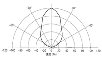
- 2 is a graph showing (a) an emission spectrum of a first LED, (b) an emission spectrum of a second LED, and (c) an output light spectrum emitted from an exit end of a light guide provided in the light source device of FIG. . It is a graph which shows the angle characteristic of the 1st light output from 1st LED. It is a graph which shows the angle characteristic of the 2nd light output from 2nd LED. It is a graph which shows the angle characteristic of the output light produced
- the light source device 1 includes two LEDs (light emitting diodes and semiconductor light sources) 21 and 22 that output light L1 and L2 having different wavelengths, and LEDs 21 and 22.
- FIG. 2A shows an emission spectrum of the first light L1 output from the first LED 21.
- FIG. FIG. 2B shows an emission spectrum of the second light L2 output from the second LED 22.
- 3 and 4 show the angle characteristics of the first light L1 and the second light L2, respectively.
- the first light L1 has a wider angle characteristic than the second light L2. That is, the second light L2 travels while maintaining the light beam diameter substantially constant, whereas the first light L1 has an angle characteristic in which the light beam diameter gradually increases as it travels.
- the collimator lenses 31 and 32 are arranged so that the front focal position coincides with the position of a chip (not shown) that becomes the light emitting point of each LED 21 and 22.
- the collimator lenses 31 and 32 for example, lenses having a focal length of 14 mm and a diameter of 19 mm are used.
- the dichroic mirror 4 transmits the first light L1 converted into parallel light by one collimator lens 31, and reflects the second light L2 converted into parallel light by the other collimator lens 32, thereby 2
- the two lights L1 and L2 are combined on the same optical path.
- the condenser lens 5 may have the same specifications as the collimator lenses 31 and 32, or may have different specifications.
- the aperture stop 6 adjusts the beam diameters of the two lights L1 and L2 so that the numerical apertures of the two lights L1 and L2 incident on the incident end 7a of the light guide 7 are substantially matched.
- the numerical apertures of the light beams L1 and L2 should be equal to a degree that satisfies the accuracy of color uniformity determined for the output light according to the purpose of use such as observation and measurement, that is, within a permissible range of color unevenness. That's fine.
- the aperture stop 6 is disposed so that the center of the opening 6a coincides with the optical axes of the lights L1 and L2 synthesized by the dichroic mirror 4.
- the diameter (opening diameter) of the opening 6a is equal to or smaller than the light beam diameter of the light having the narrow angle characteristic of the first light L1 and the second light L2, and preferably the same as the light beam diameter.
- the diameter of the opening 6a is the same as the light beam diameter of the second light L2 that has become parallel light, and is, for example, 10 mm.
- the light guide 7 has a proximal end that is the incident end 7 a disposed at the focal position of the condenser lens 5.
- a multimode fiber having a diameter of 2 mm and a numerical aperture of 0.5 is used as the light guide 7.
- Light incident on the incident end 7 a at an incident angle smaller than 30 ° is guided by the light guide 7. It comes to be lit.
- the light source device 1 generates output light with a wide wavelength band by combining two LEDs 21 and 22 having a narrow emission spectrum wavelength band and different from each other.
- the first light L1 and the second light L2 having different wavelengths output from the LEDs 21 and 22 are converted into parallel light by the collimator lenses 31 and 32, and then combined into one by the dichroic mirror 4. .
- the combined lights L 1 and L 2 are converged by the condenser lens 5 and are incident on the light guide 7.
- FIG. 2C the output light from which the wavelength band is expanded by combining the first light L1 and the second light L2 from the emission end (not shown) of the light guide 7 is shown. Is emitted.
- the first light L1 and the second light L2 converted into parallel light are combined by the dichroic mirror 4 and then adjusted by the aperture stop 6 so that the beam diameters are the same.
- the condenser lens 5 That is, of the lights L1 and L2 incident on the aperture stop 6, the second light L2 has the entire light beam passing through the opening 6a of the aperture stop 6.
- the periphery of the first light L1 that protrudes from the light beam of the second light L2 is blocked by the aperture stop 6, and only the central portion that overlaps the light beam of the second light L2 passes through the opening 6a. To do.
- the two light beams L1 and L2 are output from the aperture stop 6 in a state where the angle characteristics are uniform at least in a region near the angle corresponding to the numerical aperture with respect to the incident angle to the incident end 7a of the light guide 7. Will be.
- the first light L ⁇ b> 1 and the second light L ⁇ b> 2 are incident on the incident end 7 a of the light guide 7 with the same numerical aperture by the condenser lens 5.
- the two light beams L1 and L2 having different angle characteristics are aligned in the directivity direction with respect to the incident end 7a of the light guide 7 by the collimator lenses 31 and 32 and the dichroic mirror 4.
- the numerical aperture when entering the incident end 7 a is matched by the aperture stop 6.
- the output light emitted from the light guide 7 is a light in which the two lights L1 and L2 are combined with at least the angular characteristics in the peripheral part of the luminous flux being uniform, thereby reducing color unevenness of the output light.
- the two lights L1 and L2 are substantially uniform even in a region where the incident angle to the incident end 7a of the light guide 7 is small due to the light distribution characteristics of the LEDs 21 and 22, the two lights L1 and L2 Can be superposed on each other in a state where the angle characteristics are uniform over the entire luminous flux.
- the output light emitted from the light guide 7 can be light with no color unevenness in which the two lights L1 and L2 are uniformly combined over the entire luminous flux.
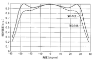
- FIG. 5 is a graph showing the angle characteristics of the lights L1 and L2 incident on the light guide 7 in the light source device 1 according to the present embodiment.
- the angle characteristics of the first light L1 and the second light L2 are substantially the same. Since this angle characteristic is preserved while the light guide 7 is being guided, the light output from the light guide 7 has the same angle characteristic as in FIG. Therefore, the output light emitted from the light guide 7 is light in which the color unevenness is reduced over the entire light beam, in which the two lights L1 and L2 are combined at substantially the same ratio at any angle.
- FIG. 6 is a graph showing the angle characteristics of the lights L1 and L2 incident on the light guide 7 when the aperture stop 6 is omitted in the configuration of FIG. 1 as a comparative example.
- the first light L ⁇ b> 1 is relatively more than the second light L ⁇ b> 2 in the region where the incident angle to the incident end 7 a is large.
- the amount of light increases, and a color difference occurs between the central portion and the peripheral portion of the light beam.
- the vertical axis represents the intensity when normalized with the intensity of each of the lights L1 and L2 at an angle of 0 ° corresponding to the center position of the light beam as 1.
- FIG. 7 shows an overall configuration of a light source device 100 according to a modification including three LEDs 21, 22, and 23.
- the light source device 100 includes two dichroic mirrors 41 and 24 in order to combine the three lights L1, L2, and L3 into a single optical path.
- the diameter (aperture diameter) of the opening 6a of the aperture stop 6 is equal to or smaller than the light flux diameter of the light having the narrowest angle characteristic among the three lights L1, L2, and L3, and preferably the same as the light flux diameter.
- the aperture stop between the dichroic mirror 42 on the rear stage side and the condenser lens 5 so that the three lights L1, L2, and L3 are converted into parallel light and combined and then pass through the aperture stop 6. 6 is preferably arranged.
- the aperture stop 6 is disposed between the dichroic mirror 4 and the condenser lens 5.
- the condenser lens 5 and the light guide 7 are arranged. You may arrange
- the diameter of the opening 6a of the aperture stop 6 is determined by the position of the aperture stop 6 in the optical axis direction.
- the numerical apertures of the two lights L1 and L2 can be matched by removing the peripheral part of the light beam from the first light L1 having a wider angle characteristic by the aperture stop 6. Further, by arranging the aperture stop 6 at a position closer to the incident end 7 a of the light guide 7, it is possible to improve the coincidence of light collecting properties to the light guide 7.
- two aperture stops 61 and 62 may be arranged in a plurality of optical paths between the collimator lenses 31 and 32 and the dichroic mirror 4.
- the opening diameters of the openings 61a and 62a of the aperture stops 61 and 62 are substantially the same.
- the opening diameters of the openings 61a and 62a need only coincide with each other to meet the accuracy of color uniformity determined for the output light according to the purpose of use such as observation and measurement.
- the numerical apertures of the two lights L1 and L2 can be matched.
- unnecessary light that is not finally incident on the light guide 7 is removed before the optical path, generation of stray light can be suppressed.
- the aperture stop 6 may be disposed in any one of the optical paths between the collimator lenses 31 and 32 and the dichroic mirror 4.
- the optical path in which the aperture stop 6 is to be disposed is an optical path through which the light having a wider angle characteristic of the two lights L1 and L2 passes.
- the diameter (aperture diameter) of the opening 6a of the aperture stop 6 is light passing through an optical path where the aperture stop 6 is not arranged, that is, light having a narrow angle characteristic, and is converted into parallel light by a collimator lens. It is the same as the beam diameter of the emitted light.
- the numerical apertures of the two lights L1 and L2 can be matched. In addition, generation of stray light can be suppressed.
- filters (light distribution characteristic adjusting portions) 81 and 82 having a light transmittance distribution as shown in FIG. 10 are provided in the openings 61a and 61b. It may be done. In FIG. 10, different hatching represents a difference in light transmittance.
- the shape (profile) of the angle characteristics of the lights L1 and L2 can be corrected. That is, when 100% of the light L1 and L2 passes through the opening 6a, the numerical apertures of the two lights L1 and L2 incident on the incident end 7a of the light guide 7 can be matched, but the profile of the angular characteristics Cannot be matched. Therefore, by independently correcting the light amounts at the respective positions of the lights L1 and L2 by the filters 81 and 82, the profiles of the two angular characteristics can be matched to generate output light with a more uniform color over the entire luminous flux. .
- the aperture stop 6 is configured separately from the other optical elements 31, 32, 4, and 5.
- the other optical elements 31, 32, and 4 are configured. , 5 may be integrated.
- FIG. 11 shows an example in which the aperture stop 6 ′ is integrated with the dichroic mirror 4 in the optical path configuration shown in FIG. 1. That is, the aperture stop 6 ′ is composed of a light shielding film 6 b provided on one surface of the dichroic mirror 4 and blocking the first light L ⁇ b> 1. By doing in this way, the optical path structure of the light source device 400 can be further simplified.
- the dichroic mirror 4 is used as the combining unit.
- the configuration of the combining unit is not limited to this, and a plurality of lights having different wavelength bands are combined into a single optical path.
- Other optical elements may be used.
- a diffractive optical element using the spectral dependence of diffraction may be used, or a half mirror may be used.
- an LD laser diode
- the LEDs 21 and 22 may be used instead of the LEDs 21 and 22.
- the collimator lenses 31 and 32 are used as the light collimating unit.
- the configuration of the light collimating unit is not limited to this, and a collimating mirror may be used.
- the condenser lens 5 is used as the light collecting unit.
- the configuration of the light collecting unit is not limited to this, and a light collecting mirror may be used.
- an optical rod may be used instead of the multimode fiber.
- Light source device 21, 22, 23 LED (semiconductor light source) 31, 32, 33 Collimator lens (light collimating part) 4, 41, 42 Dichroic mirror (synthesis unit) 5 Condenser lens (Condenser) 6,6 'aperture stop (light distribution characteristic adjustment part) 6a opening 7 light guide 7a incident end 81, 82 filter (light distribution characteristic adjusting unit)
Landscapes
- Physics & Mathematics (AREA)
- General Physics & Mathematics (AREA)
- Optics & Photonics (AREA)
- Spectroscopy & Molecular Physics (AREA)
- Engineering & Computer Science (AREA)
- General Engineering & Computer Science (AREA)
- Optical Couplings Of Light Guides (AREA)
- Non-Portable Lighting Devices Or Systems Thereof (AREA)
- Instruments For Viewing The Inside Of Hollow Bodies (AREA)
Description
本発明は、光源装置に関するものである。
従来、異なる波長帯域の光を出力する複数の光源を組み合わせた光源装置が知られている(例えば、特許文献1参照。)。特許文献1では、可視光全域に発光スペクトルを有する白色光源と、比較的狭い波長帯域の光を出力する励起光源とを用いている。2つの光源から別々に出力される白色光および励起光の空間的な強度分布は、互いに異なる。したがって、白色光および励起光を試料の同一位置に照射して正確に解析するためには、照射位置におけるこれらの光の空間的な強度分布を一致させることが必要となる。特許文献1では、白色光および励起光をライトガイドの入射端に集光するレンズの焦点位置を、入射端から光軸方向にずらすことによって、入射端における白色光および励起光の強度分布の差異の最小化を図っている。
一方、近年、上述の白色光源や励起光源のようなランプ型の光源に代えて、LEDのような半導体光源が用いられるようになってきている。半導体光源は、長寿命、高効率、高レスポンスなどの特徴を有する。半導体光源から出力される光の波長帯域は狭い。したがって、広い波長帯域の光が必要な場合には、複数の半導体光源を組み合わせて用い、複数の波長の光を合成している。
半導体光源が出力する光の角度特性は、チップの材質や構造、またはパッケージの構造などに依存して異なる。光の角度特性はライトガイドを導光している間も保存される。したがって、特許文献1のように、ライトガイドの入射端における光の強度分布を調節しただけでは、ライトガイドから出射された後の各光の角度特性の差異に起因して光の強度分布間に差異が生じ、その結果、試料の照射位置において色むらが生じるという問題がある。
本発明は、上述した事情に鑑みてなされたものであって、複数の半導体光源からの光を合成して出力光を生成する光源装置において、個々の半導体光源からの光の角度特性に差異があっても、色むらを低減した出力光を生成することができる光源装置を提供することを目的とする。
上記目的を達成するため、本発明は以下の手段を提供する。
本発明は、互いに異なる波長の光を出力する複数の半導体光源と、該複数の半導体光源から出力された各光を平行光にする複数の光平行化部と、該複数の光平行化部によって生成された複数の平行光を単一の光路に合成する合成部と、前記単一の光路上に入射端が配置され該入射端に入射された光を出射端に導光するライトガイドと、前記合成部によって合成された平行光を前記ライトガイドの入射端に集光する集光部と、前記ライトガイドの前記入射端に入射する前記複数の光の開口数を略一致させるようにこれら複数の光の光束径を調節する配光特性調節部とを備える光源装置を提供する。
本発明は、互いに異なる波長の光を出力する複数の半導体光源と、該複数の半導体光源から出力された各光を平行光にする複数の光平行化部と、該複数の光平行化部によって生成された複数の平行光を単一の光路に合成する合成部と、前記単一の光路上に入射端が配置され該入射端に入射された光を出射端に導光するライトガイドと、前記合成部によって合成された平行光を前記ライトガイドの入射端に集光する集光部と、前記ライトガイドの前記入射端に入射する前記複数の光の開口数を略一致させるようにこれら複数の光の光束径を調節する配光特性調節部とを備える光源装置を提供する。
本発明によれば、複数の半導体光源から出力された、波長の異なる複数の光は、光平行化部によって平行光に変換された後、合成部によって1つに合成され、ライトガイドの入射端に入射される。これにより、ライトガイドの出射端からは、個々の半導体光源から出力される光に対して広い波長帯域を有する出力光を出射することができる。
この場合に、複数の光は、ライトガイドの入射端に入射される際の開口数が互いに略一致するように配光特性調節部によって調節されることによって、ライトガイドの入射端への入射角度に関して少なくとも開口数に相当する角度の近傍の領域において角度特性が互いに略同一となるように補正される。これにより、個々の半導体光源からの光の角度特性に差異があっても、色むらを低減した出力光を生成することができる。
上記発明においては、前記配光特性調節部が、開口絞りを備えていてもよい。
このようにすることで、簡便な構成でありながら、ライトガイドの入射端に入射する複数の光の開口数を精度良く一致させることができる。
このようにすることで、簡便な構成でありながら、ライトガイドの入射端に入射する複数の光の開口数を精度良く一致させることができる。
上記の前記開口絞りを備える構成においては、前記開口絞りが、前記光平行化部と前記集光部との間に配置された構成であってもよい。
このようにすることで、複数の光が平行光である位置に開口絞りを配置することによって、開口絞りの光軸方向の位置精度を緩くすることができる。
このようにすることで、複数の光が平行光である位置に開口絞りを配置することによって、開口絞りの光軸方向の位置精度を緩くすることができる。
この構成においては、前記開口絞りが、前記合成部と前記集光部との間に配置されていてもよい。
このようにすることで、単一の開口絞りを用いて複数の光の開口数を精度よく一致させることができる。
このようにすることで、単一の開口絞りを用いて複数の光の開口数を精度よく一致させることができる。
または、前記開口絞りが、前記光平行化部と前記合成部との間に配置された構成であってもよい。
このようにすることで、ライトガイドに入射されない光をより前段側において除去することによって、迷光の発生を抑制することができる。
このようにすることで、ライトガイドに入射されない光をより前段側において除去することによって、迷光の発生を抑制することができる。
前記開口絞りが、前記光平行化部と前記合成部との間に配置された構成においては、前記開口絞りが、前記複数の光平行化部と前記合成部との間の複数の光路にそれぞれ配置され、各々の前記開口絞りの開口径が略同一であることとしてもよい。
このようにすることで、複数の光の開口数を精度良く一致させることができる。さらに、ライトガイドに入射されない光をより前段側において除去することによって、迷光の発生を抑制することができる。
このようにすることで、複数の光の開口数を精度良く一致させることができる。さらに、ライトガイドに入射されない光をより前段側において除去することによって、迷光の発生を抑制することができる。
前記開口絞りが、前記光平行化部と前記合成部との間に配置された構成においては、前記配光特性調節部が、前記開口絞りの開口部に設けられ該開口部を透過する光の光量を調節するフィルタを備え、該フィルタが、略同一の光束径に変換された複数の光の空間的な強度分布を一致させるような光透過率の分布を有することとしてもよい。
このようにすることで、出力光の色を光束全体にわたってさらに均一とすることができる。
このようにすることで、出力光の色を光束全体にわたってさらに均一とすることができる。
本発明によれば、複数の半導体光源からの光を合成して出力光を生成する光源装置において、個々の半導体光源からの光の角度特性に差異があっても、色むらを低減した出力光を生成することができるという効果を奏する。
以下、本発明の一実施形態に係る光源装置1について図面を参照して説明する。
本実施形態に係る光源装置1は、図1に示されるように、互いに異なる波長の光L1,L2を出力する2つのLED(発光ダイオード、半導体光源)21,22と、各LED21,22からの光L1,L2を平行光に変換する2つのコリメータレンズ(光平行化部)31,32と、これらコリメータレンズ31,32を通過した光L1,L2を単一の光路に合成するダイクロイックミラー(合成部)4と、該ダイクロイックミラー4によって合成された光を集束するコンデンサレンズ(集光部)5と、ダイクロイックミラー4とコンデンサレンズ5との間に配置された開口絞り(配光特性調節部)6と、コンデンサレンズ5によって集束された光が入射されるライトガイド7とを備えている。
本実施形態に係る光源装置1は、図1に示されるように、互いに異なる波長の光L1,L2を出力する2つのLED(発光ダイオード、半導体光源)21,22と、各LED21,22からの光L1,L2を平行光に変換する2つのコリメータレンズ(光平行化部)31,32と、これらコリメータレンズ31,32を通過した光L1,L2を単一の光路に合成するダイクロイックミラー(合成部)4と、該ダイクロイックミラー4によって合成された光を集束するコンデンサレンズ(集光部)5と、ダイクロイックミラー4とコンデンサレンズ5との間に配置された開口絞り(配光特性調節部)6と、コンデンサレンズ5によって集束された光が入射されるライトガイド7とを備えている。
図2の(a)は、第1のLED21から出力される第1の光L1の発光スペクトルを示している。図2の(b)は、第2のLED22から出力される第2の光L2の発光スペクトルを示している。図3および図4は、第1の光L1および第2の光L2の角度特性をそれぞれ示している。図3および図4に示されるように、第1の光L1は、第2の光L2に比べて広い角度特性を有している。すなわち、第2の光L2は光束径を略一定に維持したまま進むのに対し、第1の光L1は進行するに従って光束径が徐々に広がっていく角度特性を有している。
コリメータレンズ31,32は、前側焦点位置が各LED21,22の発光点となる図示しないチップの位置と一致するように配置されている。コリメータレンズ31,32としては、例えば、焦点距離が14mm、直径が19mmのものが用いられる。
ダイクロイックミラー4は、一方のコリメータレンズ31によって平行光に変換された第1の光L1を透過し、他方のコリメータレンズ32によって平行光に変換された第2の光L2を反射することによって、2つの光L1,L2を同一の光路上に合成する。
コンデンサレンズ5は、コリメータレンズ31,32と同一の仕様のものが用いられてもよく、異なる仕様のものが用いられてもよい。
ダイクロイックミラー4は、一方のコリメータレンズ31によって平行光に変換された第1の光L1を透過し、他方のコリメータレンズ32によって平行光に変換された第2の光L2を反射することによって、2つの光L1,L2を同一の光路上に合成する。
コンデンサレンズ5は、コリメータレンズ31,32と同一の仕様のものが用いられてもよく、異なる仕様のものが用いられてもよい。
開口絞り6は、ライトガイド7の入射端7aに入射する2つの光L1,L2の開口数を略一致させるように、これらの光L1,L2の光束径を調節する。光L1,L2の開口数は、観察、計測等の使用目的に応じて出力光に対して定められる色の均一性の精度を満たす程度、すなわち色むらの許容範囲に収まる程度に一致していればよい。本実施形態では、開口絞り6は、開口部6aの中心が、ダイクロイックミラー4によって合成された光L1,L2の光軸に一致するように、配置されている。開口部6aの直径(開口径)は、第1の光L1および第2の光L2のうち狭い角度特性を有する方の光の光束径以下、好ましくは該光束径と同一である。本実施形態においては、開口部6aの直径は、平行光となった第2の光L2の光束径と同一であり、例えば、10mmである。
ライトガイド7は、入射端7aである基端が、コンデンサレンズ5の焦点位置に配置されている。ライトガイド7としては、例えば、直径が2mm、開口数が0.5であるマルチモードファイバが用いられ、入射端7aに対して30°よりも小さい入射角度で入射した光がライトガイド7によって導光されるようになっている。
次に、このように構成された光源装置1の作用について説明する。
本実施形態に係る光源装置1は、発光スペクトルの波長帯域が狭くかつ互いに異なるLED21,22を2つ組み合わせることによって、広い波長帯域の出力光を生成するものである。各LED21,22から出力された互いに異なる波長の第1の光L1および第2の光L2は、コリメータレンズ31,32によってそれぞれ平行光に変換された後、ダイクロイックミラー4によって1つに合成される。合成された光L1,L2は、コンデンサレンズ5によって集束されてライトガイド7に入射される。これにより、ライトガイド7の図示しない出射端からは、図2の(c)に示されるように、第1の光L1と第2の光L2とが合成されて波長帯域が拡大された出力光が出射される。
本実施形態に係る光源装置1は、発光スペクトルの波長帯域が狭くかつ互いに異なるLED21,22を2つ組み合わせることによって、広い波長帯域の出力光を生成するものである。各LED21,22から出力された互いに異なる波長の第1の光L1および第2の光L2は、コリメータレンズ31,32によってそれぞれ平行光に変換された後、ダイクロイックミラー4によって1つに合成される。合成された光L1,L2は、コンデンサレンズ5によって集束されてライトガイド7に入射される。これにより、ライトガイド7の図示しない出射端からは、図2の(c)に示されるように、第1の光L1と第2の光L2とが合成されて波長帯域が拡大された出力光が出射される。
ここで、平行光に変換された第1の光L1および第2の光L2は、ダイクロイックミラー4によって1つに合成された後、開口絞り6によって光束径が互いに同一となるように調節されてからコンデンサレンズ5に入射される。すなわち、開口絞り6に入射した光L1,L2のうち、第2の光L2は全光束が開口絞り6の開口部6aを通過する。一方、第1の光L1は、第2の光L2の光束からはみ出した周辺部が開口絞り6によって遮断され、第2の光L2の光束と重畳している中央部分のみが開口部6aを通過する。これにより、開口絞り6からは、2つの光L1,L2が、ライトガイド7の入射端7aへの入射角度に関して少なくとも開口数に相当する角度の近傍の領域において、角度特性が揃った状態で出力されることとなる。そして、第1の光L1および第2の光L2は、コンデンサレンズ5によって同一の開口数をなしてライトガイド7の入射端7aに入射される。
このように、本実施形態によれば、互いに異なる角度特性を有する2つの光L1,L2は、コリメータレンズ31,32およびダイクロイックミラー4によってライトガイド7の入射端7aに対する指向方向が揃えられ、さらに入射端7aに入射する際の開口数が開口絞り6によって一致させられる。これにより、ライトガイド7から出射される出力光は、少なくとも光束の周辺部における角度特性が揃った状態で2つの光L1,L2が合成された光となるので、出力光の色むらを低減することができるという利点がある。
さらに、LED21,22の配光特性上、ライトガイド7の入射端7aへの入射角度が小さい領域においても2つの光L1,L2の角度特性がほぼ揃っている場合は、2つの光L1,L2を光束全体にわたって角度特性が揃った状態で互いに重畳させることができる。この場合は、ライトガイド7から出射される出力光を、光束全体にわたって2つの光L1,L2が均一に合成された色むらのない光とすることができる。
図5は、本実施形態に係る光源装置1において、ライトガイド7に入射される光L1,L2の角度特性を示すグラフである。図5に示されるように、第1の光L1および第2の光L2の角度特性は略一致している。この角度特性は、ライトガイド7を導光している間も保存されるので、ライトガイド7から出力される光も図5と同様の角度特性を有する。したがって、ライトガイド7から出射される出力光は、いずれの角度においても2つの光L1,L2が略同一の割合で合成された、光束全体にわたって色むらが低減された光となる。
図6は、比較例として、図1の構成において開口絞り6を省いた場合の、ライトガイド7に入射される各光L1,L2の角度特性を示すグラフである。図6に示されるように、開口絞り6を備えない光源装置においては、入射端7aへの入射角度が大きい領域において、第2の光L2に比べて第1の光L1の方が相対的に光量が多くなり、光束の中心部と周辺部とでは色に差異が生じる。なお、図5および図6において、縦軸は、光束の中心位置に対応する角度0°における各光L1,L2の強度を1として規格化したときの強度を表している。
また、2つの光L1,L2の角度特性のばらつきを低減する方法として、2つのコリメータレンズ31,32の焦点距離を調節する方法も存在するが、この方法においては厳しい設計条件が要求される。これに対し、本実施形態によれば、簡易な光路構成でありながら、2つの光L1,L2の角度特性のばらつきを補正することができるという利点がある。特に、第1の光L1および第2の光L2が平行光である位置に開口絞り6を配置することによって、開口絞り6の位置精度を緩くすることができる。
なお、本実施形態においては、2つのLED21,22を備えることとしたが、LEDの数は適宜選択可能である。図7は、3つのLED21,22,23を備えた変形例に係る光源装置100の全体構成を示している。光源装置100は、3つの光L1,L2,L3を単一の光路に合成するために、2つのダイクロイックミラー41,24を備えている。ここで、開口絞り6の開口部6aの直径(開口径)は、3つの光L1,L2,L3のうち最も狭い角度特性を有する光の光束径以下、好ましくは該光束径と同一である。このようにすることで、3つの光L1,L2,L3が少なくとも光束の周辺部における角度特性が揃った状態で合成された出力光を生成することができる。この変形例においても、3つの光L1,L2,L3が平行光に変換されて合成された後に開口絞り6を通過するように、後段側のダイクロイックミラー42とコンデンサレンズ5との間に開口絞り6が配置されることが好ましい。
また、本実施形態においては、開口絞り6をダイクロイックミラー4とコンデンサレンズ5との間に配置することとしたが、これに代えて、図8に示されるように、コンデンサレンズ5とライトガイド7との間に配置してもよい。この変形例に係る光源装置200においては、開口絞り6の開口部6aの直径は、開口絞り6の光軸方向の位置によって決まる。
このようにした場合も、より広い角度特性を有する第1の光L1のうち光束の周辺部を開口絞り6によって除去することによって、2つの光L1,L2の開口数を一致させることができる。また、ライトガイド7の入射端7aにより近い位置に開口絞り6を配置することによって、ライトガイド7への集光性の一致性を向上することができる。
また、本実施形態においては、図9に示されるように、2つの開口絞り61,62を各コリメータレンズ31,32とダイクロイックミラー4との間の複数の光路に配置してもよい。この場合、開口絞り61,62のそれぞれの開口部61a,62aの開口径は、略同一である。開口部61a,62aの開口径は、観察、計測等の使用目的に応じて出力光に対して定められる色の均一性の精度を満たす程度に一致していればよい。
このようにした場合も、2つの光L1,L2の開口数を一致させることができる。また、最終的にライトガイド7に入射されない不要な光が光路のより前段において除去されるので、迷光の発生を抑制することができる。
このようにした場合も、2つの光L1,L2の開口数を一致させることができる。また、最終的にライトガイド7に入射されない不要な光が光路のより前段において除去されるので、迷光の発生を抑制することができる。
また、本実施形態においては、開口絞り6をコリメータレンズ31,32とダイクロイックミラー4との間のいずれか一方の光路に配置してもよい。この場合、開口絞り6が配置されるべき光路は、2つの光L1,L2のうち広い角度特性を有する方の光が通過する光路である。また、開口絞り6の開口部6aの直径(開口径)は、開口絞り6が配置されていない光路を通る光、すなわち狭い角度特性を有する方の光であって、コリメータレンズによって平行光に変換された光の光束径と同一である。
このようにした場合も、2つの光L1,L2の開口数を一致させることができる。また、迷光の発生を抑制することができる。
このようにした場合も、2つの光L1,L2の開口数を一致させることができる。また、迷光の発生を抑制することができる。
また、図9に示される変形例に係る光源装置300においては、図10に示されるような光透過率の分布を有するフィルタ(配光特性調節部)81,82が開口部61a,61bに備えられていてもよい。図10において、異なるハッチングは光透過率の違いを表している。
このようにフィルタ81,82を備えることによって、各光L1,L2の角度特性の形状(プロファイル)を補正することができる。すなわち、開口部6aにおいて光L1,L2が100%通過する場合には、ライトガイド7の入射端7aに入射する2つの光L1,L2の開口数を一致させることはできるが、角度特性のプロファイルを一致させることはできない。そこで、フィルタ81,82によって光L1,L2の各位置における光量を独立に補正することによって、2つの角度特性のプロファイルも一致させ、光束全体にわたってさらに色が均一な出力光を生成することができる。
また、本実施形態においては、開口絞り6が他の光学素子31,32,4,5と別体で構成されていることとしたが、これに代えて、他の光学素子31,32,4,5と一体に構成されていてもよい。図11は、図1に示される光路構成において、開口絞り6’をダイクロイックミラー4と一体に構成した例を示している。すなわち、開口絞り6’は、ダイクロイックミラー4の一方の面に設けられた、第1の光L1を遮断する遮光膜6bから構成されている。このようにすることで、光源装置400の光路構成をさらに簡易にすることができる。
また、本実施形態においては、合成部としてダイクロイックミラー4を用いることとしたが、合成部の構成はこれに限定されるものではなく、波長帯域の異なる複数の光を単一の光路に合成する他の光学素子を用いてもよい。例えば、回折の分光依存性を利用した回折型の光学素子を用いてもよく、ハーフミラーを用いてもよい。また、本実施形態においては、LED21,22に代えてLD(レーザダイオード)を用いてもよい。
また、本実施形態においては、光平行化部としてコリメータレンズ31,32を用いることとしたが、光平行化部の構成はこれに限定されるものではなく、コリメートミラーを用いてもよい。また、本実施形態においては、集光部としてコンデンサレンズ5を用いることとしたが、集光部の構成はこれに限定されるものではなく、集光ミラーを用いてもよい。また、ライトガイド7の具体例として、マルチモードファイバに代えて、光学ロッドを用いてもよい。
1,100,200,300,400 光源装置
21,22,23 LED(半導体光源)
31,32,33 コリメータレンズ(光平行化部)
4,41,42 ダイクロイックミラー(合成部)
5 コンデンサレンズ(集光部)
6,6’ 開口絞り(配光特性調節部)
6a 開口部
7 ライトガイド
7a 入射端
81,82 フィルタ(配光特性調節部)
21,22,23 LED(半導体光源)
31,32,33 コリメータレンズ(光平行化部)
4,41,42 ダイクロイックミラー(合成部)
5 コンデンサレンズ(集光部)
6,6’ 開口絞り(配光特性調節部)
6a 開口部
7 ライトガイド
7a 入射端
81,82 フィルタ(配光特性調節部)
Claims (7)
- 互いに異なる波長の光を出力する複数の半導体光源と、
該複数の半導体光源から出力された各光を平行光にする複数の光平行化部と、
該複数の光平行化部によって生成された複数の平行光を単一の光路に合成する合成部と、
前記単一の光路上に入射端が配置され該入射端に入射された光を出射端に導光するライトガイドと、
前記合成部によって合成された平行光を前記ライトガイドの入射端に集光する集光部と、
前記ライトガイドの前記入射端に入射する前記複数の光の開口数を略一致させるようにこれら複数の光の光束径を調節する配光特性調節部とを備える光源装置。 - 前記配光特性調節部が、開口絞りを備える請求項1に記載の光源装置。
- 前記開口絞りが、前記光平行化部と前記集光部との間に配置されている請求項2に記載の光源装置。
- 前記開口絞りが、前記合成部と前記集光部との間に配置されている請求項3に記載の光源装置。
- 前記開口絞りが、前記光平行化部と前記合成部との間に配置されている請求項3に記載の光源装置。
- 前記開口絞りが、前記複数の光平行化部と前記合成部との間の複数の光路にそれぞれ配置され、各々の前記開口絞りの開口径が略同一である請求項5に記載の光源装置。
- 前記配光特性調節部が、前記開口絞りの開口部に設けられ該開口部を透過する光の光量を調節するフィルタを備え、
該フィルタが、略同一の光束径に変換された複数の光の空間的な強度分布を一致させるような光透過率の分布を有する請求項5または請求項6に記載の光源装置。
Priority Applications (2)
| Application Number | Priority Date | Filing Date | Title |
|---|---|---|---|
| EP13809967.6A EP2865936A4 (en) | 2012-06-25 | 2013-06-19 | LIGHT SOURCE DEVICE |
| US14/571,397 US9482870B2 (en) | 2012-06-25 | 2014-12-16 | Light source apparatus |
Applications Claiming Priority (2)
| Application Number | Priority Date | Filing Date | Title |
|---|---|---|---|
| JP2012141927A JP6128763B2 (ja) | 2012-06-25 | 2012-06-25 | 光源装置 |
| JP2012-141927 | 2012-06-25 |
Related Child Applications (1)
| Application Number | Title | Priority Date | Filing Date |
|---|---|---|---|
| US14/571,397 Continuation US9482870B2 (en) | 2012-06-25 | 2014-12-16 | Light source apparatus |
Publications (1)
| Publication Number | Publication Date |
|---|---|
| WO2014002853A1 true WO2014002853A1 (ja) | 2014-01-03 |
Family
ID=49783011
Family Applications (1)
| Application Number | Title | Priority Date | Filing Date |
|---|---|---|---|
| PCT/JP2013/066880 Ceased WO2014002853A1 (ja) | 2012-06-25 | 2013-06-19 | 光源装置 |
Country Status (4)
| Country | Link |
|---|---|
| US (1) | US9482870B2 (ja) |
| EP (1) | EP2865936A4 (ja) |
| JP (1) | JP6128763B2 (ja) |
| WO (1) | WO2014002853A1 (ja) |
Families Citing this family (7)
| Publication number | Priority date | Publication date | Assignee | Title |
|---|---|---|---|---|
| US10842367B2 (en) | 2014-05-30 | 2020-11-24 | Sony Corporation | Illumination apparatus, method and medical imaging system |
| JP6438830B2 (ja) * | 2015-04-20 | 2018-12-19 | 富士フイルム株式会社 | 位置調整方法 |
| US20160327721A1 (en) * | 2015-05-04 | 2016-11-10 | Corning Incorporated | Optical fiber lighting device and method |
| CN110691545B (zh) | 2017-06-02 | 2021-06-18 | 奥林巴斯株式会社 | 内窥镜光源装置 |
| JP6642654B2 (ja) * | 2018-08-28 | 2020-02-12 | ソニー株式会社 | 照明装置、照明方法、内視鏡システム及び医療用観察システム |
| JP2020091399A (ja) * | 2018-12-05 | 2020-06-11 | ウシオ電機株式会社 | 露光用光源装置 |
| DE102020126260A1 (de) * | 2019-10-17 | 2021-04-22 | Phoseon Technology, Inc. | Verfahren und Systeme für ein Mehrwellenlängen-Beleuchtungssystem |
Citations (7)
| Publication number | Priority date | Publication date | Assignee | Title |
|---|---|---|---|---|
| JP2002051969A (ja) * | 2000-08-08 | 2002-02-19 | Asahi Optical Co Ltd | 電子内視鏡装置 |
| JP2002065602A (ja) * | 2000-08-25 | 2002-03-05 | Asahi Optical Co Ltd | 照明光学系及び内視鏡装置 |
| JP2005342431A (ja) | 2004-06-07 | 2005-12-15 | Pentax Corp | 光源装置 |
| JP2005342033A (ja) * | 2004-05-31 | 2005-12-15 | Pentax Corp | 内視鏡用光源装置 |
| JP2005342034A (ja) * | 2004-05-31 | 2005-12-15 | Pentax Corp | 内視鏡用光源装置 |
| JP2006026128A (ja) * | 2004-07-16 | 2006-02-02 | Pentax Corp | 内視鏡用光源装置 |
| WO2011162111A1 (ja) * | 2010-06-25 | 2011-12-29 | オリンパスメディカルシステムズ株式会社 | 内視鏡装置 |
Family Cites Families (8)
| Publication number | Priority date | Publication date | Assignee | Title |
|---|---|---|---|---|
| US4924870A (en) * | 1989-01-13 | 1990-05-15 | Fiberoptic Sensor Technologies, Inc. | Fiber optic sensors |
| EP0560383B1 (en) * | 1992-03-13 | 1997-07-23 | Fuji Photo Film Co., Ltd. | Optical apparatus for image scanning |
| JP2901801B2 (ja) * | 1992-03-13 | 1999-06-07 | 富士写真フイルム株式会社 | 画像読取光学装置 |
| US6582363B2 (en) | 2000-08-25 | 2003-06-24 | Pentax Corporation | Video endoscope system and illumination optical system |
| JP4393049B2 (ja) * | 2002-09-17 | 2010-01-06 | キヤノン株式会社 | 走査光学系及びそれを用いた画像形成装置 |
| TWI269012B (en) * | 2005-12-21 | 2006-12-21 | Coretronic Corp | Illumination system |
| US8670178B2 (en) * | 2009-12-08 | 2014-03-11 | Spectral Applied Research Inc. | Imaging distal end of multimode fiber |
| EP2681607B1 (en) * | 2011-03-01 | 2015-11-04 | GE Healthcare Bio-Sciences Corp. | Laser beam selectors |
-
2012
- 2012-06-25 JP JP2012141927A patent/JP6128763B2/ja active Active
-
2013
- 2013-06-19 WO PCT/JP2013/066880 patent/WO2014002853A1/ja not_active Ceased
- 2013-06-19 EP EP13809967.6A patent/EP2865936A4/en not_active Withdrawn
-
2014
- 2014-12-16 US US14/571,397 patent/US9482870B2/en not_active Expired - Fee Related
Patent Citations (7)
| Publication number | Priority date | Publication date | Assignee | Title |
|---|---|---|---|---|
| JP2002051969A (ja) * | 2000-08-08 | 2002-02-19 | Asahi Optical Co Ltd | 電子内視鏡装置 |
| JP2002065602A (ja) * | 2000-08-25 | 2002-03-05 | Asahi Optical Co Ltd | 照明光学系及び内視鏡装置 |
| JP2005342033A (ja) * | 2004-05-31 | 2005-12-15 | Pentax Corp | 内視鏡用光源装置 |
| JP2005342034A (ja) * | 2004-05-31 | 2005-12-15 | Pentax Corp | 内視鏡用光源装置 |
| JP2005342431A (ja) | 2004-06-07 | 2005-12-15 | Pentax Corp | 光源装置 |
| JP2006026128A (ja) * | 2004-07-16 | 2006-02-02 | Pentax Corp | 内視鏡用光源装置 |
| WO2011162111A1 (ja) * | 2010-06-25 | 2011-12-29 | オリンパスメディカルシステムズ株式会社 | 内視鏡装置 |
Non-Patent Citations (1)
| Title |
|---|
| See also references of EP2865936A4 * |
Also Published As
| Publication number | Publication date |
|---|---|
| US9482870B2 (en) | 2016-11-01 |
| EP2865936A1 (en) | 2015-04-29 |
| JP6128763B2 (ja) | 2017-05-17 |
| JP2014007057A (ja) | 2014-01-16 |
| US20150098242A1 (en) | 2015-04-09 |
| EP2865936A4 (en) | 2016-02-24 |
Similar Documents
| Publication | Publication Date | Title |
|---|---|---|
| US9482870B2 (en) | Light source apparatus | |
| KR101825530B1 (ko) | 발광 장치 및 관련 광원 시스템 | |
| JP5983613B2 (ja) | コリメータ装置及びレーザ光源 | |
| US10842367B2 (en) | Illumination apparatus, method and medical imaging system | |
| JP6444674B2 (ja) | レーザ作動光源 | |
| US9541721B2 (en) | Laser device | |
| US11786116B2 (en) | Multiple source endoscopy illumination system with adjustable angular distribution and wide field of view | |
| US8837043B2 (en) | Light source arrangement for an illumination device of a medical-optical observation apparatus | |
| US11051684B2 (en) | Endoscope light source device | |
| JPWO2016117108A1 (ja) | 多波長レーザ光合波モジュール | |
| US20230335971A1 (en) | Light source device | |
| US20150138753A1 (en) | Light-source apparatus | |
| JPWO2018037548A1 (ja) | 発光装置 | |
| CN116774535B (zh) | 一种用于掩模对准光刻设备的照明系统 | |
| TWI486700B (zh) | 光源及其應用的投影系統 | |
| JP2022105473A (ja) | 画像アプリケーション用の適応照明システムのための方法およびシステム | |
| US11177635B2 (en) | Light source device | |
| JP2023148533A (ja) | 光源装置 | |
| KR102525592B1 (ko) | 조명장치 | |
| CN116940881A (zh) | 光合波器 | |
| JP2010048641A (ja) | 単色光照射装置 |
Legal Events
| Date | Code | Title | Description |
|---|---|---|---|
| 121 | Ep: the epo has been informed by wipo that ep was designated in this application |
Ref document number: 13809967 Country of ref document: EP Kind code of ref document: A1 |
|
| NENP | Non-entry into the national phase |
Ref country code: DE |
|
| WWE | Wipo information: entry into national phase |
Ref document number: 2013809967 Country of ref document: EP |