WO2014002928A1 - トラッキング調整用装置、トラッキング調整方法及びプログラム - Google Patents
トラッキング調整用装置、トラッキング調整方法及びプログラム Download PDFInfo
- Publication number
- WO2014002928A1 WO2014002928A1 PCT/JP2013/067191 JP2013067191W WO2014002928A1 WO 2014002928 A1 WO2014002928 A1 WO 2014002928A1 JP 2013067191 W JP2013067191 W JP 2013067191W WO 2014002928 A1 WO2014002928 A1 WO 2014002928A1
- Authority
- WO
- WIPO (PCT)
- Prior art keywords
- adjustment
- tracking
- lens
- focus
- evaluation value
- Prior art date
- Legal status (The legal status is an assumption and is not a legal conclusion. Google has not performed a legal analysis and makes no representation as to the accuracy of the status listed.)
- Ceased
Links
Images









Classifications
-
- G—PHYSICS
- G01—MEASURING; TESTING
- G01S—RADIO DIRECTION-FINDING; RADIO NAVIGATION; DETERMINING DISTANCE OR VELOCITY BY USE OF RADIO WAVES; LOCATING OR PRESENCE-DETECTING BY USE OF THE REFLECTION OR RERADIATION OF RADIO WAVES; ANALOGOUS ARRANGEMENTS USING OTHER WAVES
- G01S3/00—Direction-finders for determining the direction from which infrasonic, sonic, ultrasonic or electromagnetic waves, or particle emission, not having a directional significance, are being received
- G01S3/78—Direction-finders for determining the direction from which infrasonic, sonic, ultrasonic or electromagnetic waves, or particle emission, not having a directional significance, are being received using electromagnetic waves other than radio waves
- G01S3/782—Systems for determining direction or deviation from predetermined direction
- G01S3/785—Systems for determining direction or deviation from predetermined direction using adjustment of orientation of directivity characteristics of a detector or detector system to give a desired condition of signal derived from that detector or detector system
- G01S3/786—Systems for determining direction or deviation from predetermined direction using adjustment of orientation of directivity characteristics of a detector or detector system to give a desired condition of signal derived from that detector or detector system the desired condition being maintained automatically
- G01S3/7864—T.V. type tracking systems
-
- G—PHYSICS
- G02—OPTICS
- G02B—OPTICAL ELEMENTS, SYSTEMS OR APPARATUS
- G02B7/00—Mountings, adjusting means, or light-tight connections, for optical elements
- G02B7/28—Systems for automatic generation of focusing signals
-
- G—PHYSICS
- G02—OPTICS
- G02B—OPTICAL ELEMENTS, SYSTEMS OR APPARATUS
- G02B15/00—Optical objectives with means for varying the magnification
- G02B15/14—Optical objectives with means for varying the magnification by axial movement of one or more lenses or groups of lenses relative to the image plane for continuously varying the equivalent focal length of the objective
- G02B15/142—Optical objectives with means for varying the magnification by axial movement of one or more lenses or groups of lenses relative to the image plane for continuously varying the equivalent focal length of the objective having two groups only
-
- G—PHYSICS
- G02—OPTICS
- G02B—OPTICAL ELEMENTS, SYSTEMS OR APPARATUS
- G02B7/00—Mountings, adjusting means, or light-tight connections, for optical elements
- G02B7/28—Systems for automatic generation of focusing signals
- G02B7/36—Systems for automatic generation of focusing signals using image sharpness techniques, e.g. image processing techniques for generating autofocus signals
-
- G—PHYSICS
- G03—PHOTOGRAPHY; CINEMATOGRAPHY; ANALOGOUS TECHNIQUES USING WAVES OTHER THAN OPTICAL WAVES; ELECTROGRAPHY; HOLOGRAPHY
- G03B—APPARATUS OR ARRANGEMENTS FOR TAKING PHOTOGRAPHS OR FOR PROJECTING OR VIEWING THEM; APPARATUS OR ARRANGEMENTS EMPLOYING ANALOGOUS TECHNIQUES USING WAVES OTHER THAN OPTICAL WAVES; ACCESSORIES THEREFOR
- G03B13/00—Viewfinders; Focusing aids for cameras; Means for focusing for cameras; Autofocus systems for cameras
- G03B13/32—Means for focusing
- G03B13/34—Power focusing
- G03B13/36—Autofocus systems
-
- H—ELECTRICITY
- H04—ELECTRIC COMMUNICATION TECHNIQUE
- H04N—PICTORIAL COMMUNICATION, e.g. TELEVISION
- H04N17/00—Diagnosis, testing or measuring for television systems or their details
- H04N17/002—Diagnosis, testing or measuring for television systems or their details for television cameras
-
- H—ELECTRICITY
- H04—ELECTRIC COMMUNICATION TECHNIQUE
- H04N—PICTORIAL COMMUNICATION, e.g. TELEVISION
- H04N23/00—Cameras or camera modules comprising electronic image sensors; Control thereof
- H04N23/60—Control of cameras or camera modules
- H04N23/63—Control of cameras or camera modules by using electronic viewfinders
- H04N23/631—Graphical user interfaces [GUI] specially adapted for controlling image capture or setting capture parameters
-
- H—ELECTRICITY
- H04—ELECTRIC COMMUNICATION TECHNIQUE
- H04N—PICTORIAL COMMUNICATION, e.g. TELEVISION
- H04N23/00—Cameras or camera modules comprising electronic image sensors; Control thereof
- H04N23/60—Control of cameras or camera modules
- H04N23/63—Control of cameras or camera modules by using electronic viewfinders
- H04N23/633—Control of cameras or camera modules by using electronic viewfinders for displaying additional information relating to control or operation of the camera
- H04N23/635—Region indicators; Field of view indicators
-
- H—ELECTRICITY
- H04—ELECTRIC COMMUNICATION TECHNIQUE
- H04N—PICTORIAL COMMUNICATION, e.g. TELEVISION
- H04N23/00—Cameras or camera modules comprising electronic image sensors; Control thereof
- H04N23/60—Control of cameras or camera modules
- H04N23/66—Remote control of cameras or camera parts, e.g. by remote control devices
-
- H—ELECTRICITY
- H04—ELECTRIC COMMUNICATION TECHNIQUE
- H04N—PICTORIAL COMMUNICATION, e.g. TELEVISION
- H04N23/00—Cameras or camera modules comprising electronic image sensors; Control thereof
- H04N23/60—Control of cameras or camera modules
- H04N23/67—Focus control based on electronic image sensor signals
- H04N23/673—Focus control based on electronic image sensor signals based on contrast or high frequency components of image signals, e.g. hill climbing method
-
- H—ELECTRICITY
- H04—ELECTRIC COMMUNICATION TECHNIQUE
- H04N—PICTORIAL COMMUNICATION, e.g. TELEVISION
- H04N23/00—Cameras or camera modules comprising electronic image sensors; Control thereof
- H04N23/60—Control of cameras or camera modules
- H04N23/69—Control of means for changing angle of the field of view, e.g. optical zoom objectives or electronic zooming
-
- G—PHYSICS
- G03—PHOTOGRAPHY; CINEMATOGRAPHY; ANALOGOUS TECHNIQUES USING WAVES OTHER THAN OPTICAL WAVES; ELECTROGRAPHY; HOLOGRAPHY
- G03B—APPARATUS OR ARRANGEMENTS FOR TAKING PHOTOGRAPHS OR FOR PROJECTING OR VIEWING THEM; APPARATUS OR ARRANGEMENTS EMPLOYING ANALOGOUS TECHNIQUES USING WAVES OTHER THAN OPTICAL WAVES; ACCESSORIES THEREFOR
- G03B13/00—Viewfinders; Focusing aids for cameras; Means for focusing for cameras; Autofocus systems for cameras
- G03B13/18—Focusing aids
- G03B13/30—Focusing aids indicating depth of field
-
- G—PHYSICS
- G03—PHOTOGRAPHY; CINEMATOGRAPHY; ANALOGOUS TECHNIQUES USING WAVES OTHER THAN OPTICAL WAVES; ELECTROGRAPHY; HOLOGRAPHY
- G03B—APPARATUS OR ARRANGEMENTS FOR TAKING PHOTOGRAPHS OR FOR PROJECTING OR VIEWING THEM; APPARATUS OR ARRANGEMENTS EMPLOYING ANALOGOUS TECHNIQUES USING WAVES OTHER THAN OPTICAL WAVES; ACCESSORIES THEREFOR
- G03B2205/00—Adjustment of optical system relative to image or object surface other than for focusing
- G03B2205/0046—Movement of one or more optical elements for zooming
Definitions
- the present invention relates to a tracking adjustment apparatus, a tracking adjustment method, and a program capable of improving the accuracy of tracking adjustment (back focus adjustment) and reducing the adjustment time.
- tracking adjustment also referred to as “back focus adjustment”.
- the zoom position is set to the telephoto end, and the focus lens is moved to focus on the adjustment chart (tracking adjustment stationary object).
- the zoom position is set to the wide end, and the tracking lens arranged behind the focus lens in the optical axis direction is moved to focus on the adjustment chart.
- the tracking adjustment is completed when the above operation is repeated and the focus is not blurred even when the zoom position is changed.
- Patent Document 1 discloses a configuration in which the aperture is set to an open state when focusing by autofocus.
- Patent Document 2 discloses displaying a graph indicating a relationship between a focus position and an evaluation value of a focus state from a video signal.
- Patent Document 3 discloses a configuration in which a display changeover switch can switch between a graph indicating the relationship between the focus position and the evaluation value of the focus state and a bar graph of the evaluation value of the focus state.
- the evaluation value of the focus state is calculated from the tele-end image as shown in FIG. 12A.
- the evaluation value of the focus state is calculated from the wide end image as shown in FIG. 12B.
- the present invention has been made in view of such circumstances.
- a tracking adjustment device, a tracking adjustment method, and a program that can improve the accuracy of tracking adjustment (back focus adjustment) and can shorten the adjustment time.
- the purpose is to provide.
- a tracking adjustment apparatus includes a zoom instruction input unit that receives an instruction to move a zoom lens that can be moved to change a focal length, and focuses on a subject.
- Focus instruction input means for inputting a movement instruction for a focus lens that can be moved for alignment
- tracking instruction input means for inputting a movement instruction for a tracking lens that can be moved for changing the position of the imaging plane
- a tracking adjustment device for obtaining a video signal from a camera device equipped with a lens device having a zoom lens, a focus lens, and a tracking lens; The focus lens is moved by the focus instruction input means. Whether the zoom lens is set to the wide side position by the zoom instruction input unit and the tracking lens is moved by the tracking instruction input unit.
- an area setting means for setting a detection area for detecting the focus state of the lens apparatus with respect to the video signal acquired by the video signal acquisition means, the first adjustment based on the determination result of the determination means
- Area setting means for switching the size of the detection area between the state and the second adjustment state
- evaluation value generation means for generating an evaluation value indicating the focus state of the lens apparatus from the video signal acquired by the video signal acquisition means.
- Evaluation value generating means for generating an evaluation value within the detection area set by the area setting means in the entire screen area of the video signal; And display means for displaying the evaluation value generated by the evaluation value generating means.
- the area setting means extracts an image of a specific stationary object from the video signal, and switches the size of the detection area according to the size of the extracted image.
- the determination unit determines whether the adjustment state is the first adjustment state or the second adjustment state based on the video signal acquired from the camera device.
- the determination means is in the first adjustment state or the second adjustment based on the zoom position signal indicating the position of the zoom lens output from one of the zoom instruction input means and the lens device. It is determined whether it is in a state.
- the determination unit determines whether the adjustment state is the first adjustment state or the second adjustment state based on a user input operation.
- the evaluation value generation unit generates a graph having a different format between the first adjustment state and the second adjustment state, and the display unit is generated by the evaluation value generation unit. Display the graph.
- the tracking adjustment method includes a zoom instruction input unit that receives an instruction to move a zoom lens that can be moved to change a focal length, and a focus lens that can be moved to focus on a subject.
- the tracking lens is moved by the tracking instruction input means.
- An evaluation value generation step for generating an evaluation value indicating the focus state of the lens apparatus from the captured video signal, wherein the evaluation value is generated within the detection area set by the area setting step in the entire screen area of the video signal A value generation step, and a step of displaying the evaluation value generated by the evaluation value generation step.
- the present invention also provides a program for causing a computer device to execute the tracking adjustment method described above.
- This program can be provided by being recorded on a predetermined recording medium.
- the accuracy of back focus adjustment (tracking adjustment) can be increased, and the adjustment time can be shortened.
- the front view which shows the external appearance of an example of the apparatus for tracking adjustment which concerns on this invention 1 is an overall configuration diagram showing an example of a tracking adjustment system provided with the tracking adjustment device of FIG.
- Explanatory drawing which shows a mode that the chart for adjustment is image
- Explanatory drawing showing the screen when shooting the adjustment chart at the tele end
- Explanatory drawing showing a screen with the same detection frame size as the tele end when the adjustment chart is taken at the wide end
- the flowchart which shows the flow of the tracking adjustment process of 1st Example.
- FIG. 1 shows an appearance of an example of a tracking adjustment device according to the present invention.
- the tracking adjustment apparatus 10 shown in FIG. 1 includes a video signal input terminal 12, a monitor 14 that mainly displays a captured image, an indicator 16 that mainly displays a graph, and a speaker 18 that outputs a beep sound.
- the indicator 16 may be provided integrally with the monitor 14 and will be described below as being provided integrally with the monitor 14.
- the “POWER” switch 21 is an operation switch for switching the power of the tracking adjustment device 10 on and off.
- the “BEEP” switch 22 is an operation switch for switching on / off of a beep sound output from the speaker 18.
- the “MONITOR” switch 23 is an operation switch for switching the display of the monitor 14 on and off.
- the “MARKER” switch 24 is a switch for switching whether or not to perform marking (recording). The marking will be described later.
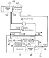
- FIG. 2 is an overall configuration diagram showing an example of a tracking adjustment system including the tracking adjustment device 10 of FIG.
- the lens apparatus 100 includes an optical member such as a zoom lens, a focus lens, and a tracking lens.
- the zoom lens is a lens that can move in the optical axis direction in order to change the focal length.
- the focus lens is a lens that can move in the optical axis direction in order to focus on the subject.
- the tracking lens is a lens that can move in the direction of its optical axis in order to change the position of the image plane.
- the tracking lens is arranged behind the focus lens (on the camera device 200 side) in the optical axis direction.
- the camera device 200 is configured to include an image sensor that captures a subject image formed by the lens device 100.
- the camera device 200 of this example outputs a video signal of HD-SDI (High Definition Serial Digital Interface).
- HD-SDI High Definition Serial Digital Interface
- the zoom demand 26 is an input device for manually specifying and inputting the zoom position (the position of the zoom lens).
- the focus demand 28 is an input device for manually specifying and inputting a focus position (a position of the focus lens).
- the lens apparatus 100 includes a zoom instruction signal input terminal 102 to which a zoom instruction signal output from the zoom demand 26 is input, and a focus instruction signal input terminal 104 to which a focus instruction signal output from the focus demand 28 is input. It has been.
- the zoom instruction signal indicates the zoom position of the movement destination, and the focus instruction signal indicates the focus position of the movement destination.
- the lens apparatus 100 is provided with a tracking adjustment knob 106 for moving the position of the tracking lens. That is, when the user turns the tracking adjustment knob 106, an instruction to move the tracking lens is manually input.
- operation devices corresponding to the zoom demand 26 and the focus demand 28 may be provided in the lens apparatus 100.
- the lens device 100 is provided with an operation device
- the lens device 100 is provided with a signal input terminal
- the lens device 100 is provided with both an operation device and a signal input terminal. Any of these may be used.
- the HD-SDI video signal is input from the camera device 200 to the video signal input terminal 12 of the tracking adjustment device 10.
- a zoom position signal is input from the zoom demand 26 to the zoom position signal input terminal 34 of the tracking adjustment device 10.
- a focus position signal is input from the focus demand 28 to the focus position signal input terminal 36 of the tracking adjustment device 10.
- the tracking adjustment device 10 includes a decoder 38 that decodes the video signal input to the video signal input terminal 12, an image memory 40 that temporarily stores the video signal decoded by the decoder 38 as an image for each frame, A high-frequency component extracting unit 42 that extracts a high-frequency component (high-frequency component) from the signal (image), and a second focus adjustment state in which the focus lens is moved or a tracking lens is moved.
- a determination unit 43 that determines whether the focus adjustment state is set, and an area setting that sets a detection area for detecting the focus state of the lens apparatus 100 for the video signal (image) based on the determination result of the determination unit 43
- the focus state is detected in the detection area set by the area setting unit 44 in the entire screen area of the unit 44 and the video signal (image),
- the image display circuit 48 converts the video signal decoded by the decoder 38 into a displayable format in the monitor 14.
- the determination unit 43, the area setting unit 44, and the evaluation value generation unit 46 are configured by a CPU (Central Processing Unit), for example.
- the high frequency component extraction unit 42 is configured by a circuit (or CPU), for example.
- the determination unit 43 of this example is in a first focus adjustment state in which the focus lens is moved by the focus demand 28 when the zoom lens is set to the tele side position (hereinafter simply referred to as “tele”) by the zoom demand 26. Judge that there is.
- the determination unit 43 is in the second focus adjustment state in which the tracking lens is moved by the tracking adjustment knob 106 when the zoom lens is set to the wide side position (hereinafter simply referred to as “wide”) by the zoom demand 26. Judge that there is.
- the area setting unit 44 switches the size of a detection area (a focus evaluation value detection area) for detecting the focus state of the lens device 100 based on the determination result of the determination unit 43.
- the area setting unit 44 is more focused in the second focus adjustment state where the zoom position is “wide” than in the first focus adjustment state where the zoom position is “tele”. Reduce the size of the evaluation value detection area. “Tele” and “Wide” are not particularly limited when they are at both ends of the movable range of the zoom position, but it is preferable to perform adjustment at both ends of the movable range of the zoom position.
- the monitor 14 in FIG. 2 also serves as the indicator 16 in FIG. 1, and can simultaneously display an image showing a video signal acquired from the camera device 200 and a graph showing the focus state of the lens device 100.
- the tracking adjustment device 10 has a focus evaluation value marking function.
- the evaluation value generation unit 46 performs marking for recording the relationship between the change in the focus position and the change in the focus evaluation value in a work memory (not shown), and the marking. A graph indicating the result is displayed on the monitor 14. Further, the evaluation value generation unit 46 causes the monitor 14 to display the peak value of the focus evaluation value and the focus position at which the focus evaluation value becomes the peak value.
- a beep sound is output from the speaker 18 when the focus evaluation value reaches a peak. Further, as shown in FIG. 1, a focus evaluation value detection frame 82 is displayed on the monitor 14 together with the image.
- the monitor 14 of this example is constituted by a small liquid crystal display (LCD). This enables precise tracking adjustment even at sites without large monitors.
- the reason why the focus evaluation value detection area is reduced during the second focus adjustment by the tracking adjustment knob 106 will be described.
- the zoom position is “tele” during the first focus adjustment by the focus demand 28, and FIG.
- a detection frame 82 is included in an image 81 of the adjustment chart 80.
- an accurate focus evaluation value for the adjustment chart 80 is generated.
- the zoom position is “wide”, and the detection frame 82 does not enter the image 81 of the adjustment chart 80 as shown in FIG. 4B.
- an image of a subject for example, a person having a different distance from the adjustment chart 80 enters the detection frame 82. Therefore, as shown in FIG. 4C, at the time of the second focus adjustment, by reducing the size of the detection frame 82, an image of a subject other than the image 81 of the adjustment chart 80 does not enter the detection frame 82. To.
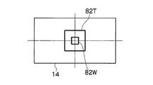
- FIG. 5 shows an example of a detection frame displayed on the monitor 14.
- reference numeral 82T is a detection frame when the zoom position is the middle to tele end
- reference numeral 82W is a detection frame when the zoom position is the wide end.
- the area setting unit 44 of the tracking adjustment device 10 switches the size of the detection frame 82 (the size of the detection area) according to the zoom position.
- FIG. 6 shows an example of the relationship between the zoom position and the size of the detection frame 82, where the horizontal axis is the zoom position and the vertical axis is the size of the detection frame 82.
- the relationship between the zoom position and the size of the detection area is not particularly limited in the case shown in FIG.
- the size of the detection area is set to a fixed first size
- the size of the detection area is set to the first size.
- a fixed second size smaller than the size may be set.
- FIG. 7 is a flowchart showing the flow of the tracking adjustment process of the first embodiment. This processing is executed according to a program by the CPU constituting the determination unit 43, the area setting unit 44, and the evaluation value generation unit 46 of the tracking adjustment device 10.
- the zoom position signal is input to the zoom position signal input terminal 34.
- the determination unit 43 of this example determines the adjustment state based on the input zoom position signal.
- step S102 processing other than the determination of tracking adjustment is executed.
- step S104 the presence / absence of a manual setting operation is determined.
- the monitor 14 is constituted by a touch panel 15.
- a “T” switch 84T and a “W” switch 84W are displayed on the touch panel 15 as manual switches for inputting the zoom position.
- “T” switch 84T is touched, “Tele” is input as the zoom position.
- “W” switch 84W is touched, “wide” is input as the zoom position.
- step S106 If there is a manual setting operation, the manual switch is read (step S106). If there is no manual setting operation, the zoom position signal input to the zoom position signal input terminal 34 is read (step S108).
- the determination unit 43 determines whether or not the zoom position is “tele”, so that the focus adjustment is performed by the focus demand 28 or the focus adjustment is performed by the tracking adjustment knob 106. Is determined (step S110). That is, the determination unit 43 determines whether the focus adjustment state is the first focus adjustment state or the second focus adjustment state based on the zoom position signal or the manual switch.
- the area setting unit 44 sets the detection frame for the focus evaluation value to a large size (step S112), and the evaluation value generating unit 46 sets the graph shape to a broken line as shown in FIG.
- the graph is generated by setting (step S114).
- the graph of FIG. 9 is generated by the evaluation value generation unit 46 based on the focus position signal input to the focus position signal input terminal 36. This graph shows the change of the focus evaluation value in the detection frame 82 with respect to the change of the focus position, and also shows the maximum value 83V of the focus evaluation value and the focus position 83P where the focus evaluation value becomes the maximum value 83V.
- the area setting unit 44 sets the focus evaluation value detection frame to a small size (step S116), and the evaluation value generation unit 46 sets the graph shape to a bar as shown in FIG. A graph is generated by setting (step S118).
- This graph is a bar-shaped graph in which the focus evaluation value changes up and down in accordance with a change in the position of the tracking lens (tracking position). That is, the focus evaluation value corresponding to the current position of the tracking lens is shown in real time.
- FIG. 10 shows a vertical bar, a horizontal bar may be used.
- the generated graph is displayed on the monitor 14 (step S120).
- the size of the focus evaluation value detection area (the size of the detection frame 82) is switched between the first focus adjustment performed by “tele” and the second focus adjustment performed by “wide”.
- the focus evaluation value is generated with the same accuracy both during the first focus adjustment for moving the lens and during the second focus adjustment for moving the tracking lens.
- 9 is automatically displayed when marking is performed by changing the focus position with “Tele”, and when the tracking position is adjusted with “Wide”, the bar-shaped graph shown in FIG. 10 is displayed. Since switching is performed automatically, tracking adjustment can be completed easily and in a short time.
- FIG. 2 shows an example in which a signal is input from the zoom demand 26 and the focus demand 28 to the tracking adjustment device 10, but the present invention is not limited to such a case.
- a zoom position signal and a focus position signal may be input from the lens apparatus 100 to the tracking adjustment apparatus 10.
- FIG. 11 is a flowchart showing the flow of the tracking adjustment process of the second embodiment. This process is executed by the CPU of the tracking adjustment apparatus 10 according to a program.
- Steps S202 to S206 are the same as steps S102 to S106 of the first embodiment shown in FIG. 7, and the description thereof is omitted here.
- step S 208 if there is no manual setting operation (NO in step S ⁇ b> 204), whether or not the adjustment is on the tele side by image processing based on the video signal acquired from the camera device 200. Is determined (step S208).
- FIG. 12A shows an example of an image (hereinafter referred to as “tele image”) obtained by imaging the adjustment chart 80 of FIG. 3 by the camera device 200 when the zoom position is “tele”.
- FIG. 12B shows an example of an image (hereinafter referred to as “wide image”) obtained by imaging the adjustment chart 80 of FIG. 3 by the camera device 200 when the zoom position is “wide”.
- the determination unit 43 of the tracking adjustment device 10 of this example determines whether or not the zoom position is “tele” based on the video signal acquired from the camera device 200. For example, based on at least one of the color distribution histogram, the color difference of the color signal, and the distribution of the high frequency component on the screen, it is determined whether it is “tele” or “wide”.
- the determination unit 43 of the lens apparatus 100 determines whether or not the high-frequency component has radial symmetry on the screen. If the high-frequency component has radial symmetry, the zoom position is “tele”. Is determined.
- Steps S210 to S220 are the same as steps S110 to S120 of the first embodiment shown in FIG. 7, and a description thereof is omitted here.
- FIG. 14A shows a state in which the adjustment chart 80 is imaged
- FIG. 14B shows an image 81 of the adjustment chart 80 in the entire screen area 84 (screen) of the video signal.
- the distance L to the adjustment chart 80 is arbitrary depending on the lens specifications and the actual shooting distance, but is 2 to 6 m, for example. However, many long-focus zoom lenses have a MOD (closest shooting distance) of about 3 m and are set to a distance longer than that.
- FIG. 15 An example of the ratio D / V between the size D of the image 81 of the adjustment chart 80 and the screen size V is shown in FIG.
- the diameter of the Siemens chart as the adjustment chart 80 (D in FIG. 14A) is 400 mm
- the D / V is 11% to 31% at the wide end.
- the focus evaluation value detection area at the wide end is selected from, for example, a square having sides of 10%, 20%, and 30% of the screen height.
- the adjustment may be made in the range of 10 to 30%.
- FIGS. 16A and 16B show examples of screens in the tracking adjustment apparatus 10.
- the monitor 14 is configured by the touch panel 15.
- the display mode changeover switches 86A and 86B on the touch panel 15 are touched, the display mode is switched.
- a display mode switch 86A for switching to the frame tracking mode is displayed.
- the “T” switch 84T and the “W” switch 84W are the same as those shown in FIG. Also in this example, the zoom position is acquired by receiving a touch operation.
- the detection frame 82 is superimposed on the captured image 87 indicating the video signal acquired from the camera device 200 and displayed.
- the CPU of the tracking adjustment device 10 tracks the main subject and also tracks the detection frame 82.
- FIG. 17 is a flowchart showing the flow of the tracking adjustment processing example of the third embodiment. This process is executed by the CPU of the tracking adjustment apparatus 10 according to a program.
- processing other than the tracking adjustment determination is executed (step S302).
- step S304 it is determined whether or not there is a switch operation. In this example, it is determined whether the “T” switch 84T, the “W” switch 84W, and the “AUTO” switch 85 shown in FIG. 16A have been operated.
- step S306 it is determined whether or not the “AUTO” switch 85 for inputting the tele / wide automatic setting instruction is operated.
- the T / W manual setting flag is turned on (step S308), and the previous operation is performed by the “T” switch 84T. It is determined whether or not the operation has been performed (step S310). If the “T” switch 84T is operated, the zoom position information is set to “tele” (step S312). If the previous operation is the “W” switch 84W, the zoom position information is set. Is set to “wide” (step S314).
- Steps S324 to S334 are the same as steps S110 to S120 in FIG. 7, and the description thereof is omitted here.
- the tracking adjustment device 10 may be configured by a computer device instead of dedicated hardware. In that case, the tracking adjustment method described in the present specification may be executed by the computer apparatus according to the program.
- the present invention also provides a computer readable program code for causing the device to perform the above-described processing, and a non-transitory and computer readable recording medium (for example, an optical disc (eg, an optical disc) storing the program code.
- a non-transitory and computer readable recording medium for example, an optical disc (eg, an optical disc) storing the program code.
- CD Compact Disc
- DVD Digital Versatile Disc
- BD Blu-ray Disc
- magnetic disk eg, hard disk, magneto-optical disk
- executable code for the method are stored.
- a zoom instruction input means for inputting a movement instruction of a zoom lens movable to change a focal length, and a focus instruction input for inputting a movement instruction of a focus lens movable to focus on a subject
- a tracking adjustment input device having tracking instruction input means for inputting a movement instruction of a tracking lens movable to change the position of the imaging plane, the zoom lens, the focus lens, and the tracking lens.
- a video signal acquisition means for acquiring a video signal from a camera device equipped with the lens apparatus, and a zoom lens is set to a tele-side position by the zoom instruction input means, and the focus lens is moved by the focus instruction input means.
- Invention 3 The tracking adjustment device according to Invention 1 or 2, wherein the determination unit determines whether the adjustment state is the first adjustment state or the second adjustment state based on the video signal acquired from the camera device. .
- the determination means is in the first adjustment state or the second adjustment state based on a zoom position signal indicating the position of the zoom lens output from one of the zoom instruction input means and the lens device.
- the tracking adjustment device according to the first or second aspect of the invention for determining whether or not.
- Invention 5 The tracking adjustment device according to Invention 1 or 2, wherein the determination means determines whether the adjustment state is the first adjustment state or the second adjustment state based on a user input operation.
- the area adjustment means extracts an image of a specific stationary object from the video signal, and switches the size of the detection area according to the size of the extracted image. Tracking adjustment according to any one of Inventions 1 to 5 Equipment.
- the evaluation value generation means generates different types of graphs in the first adjustment state and in the second adjustment state, and the display means displays the graph generated by the evaluation value generation means
- the tracking adjustment device according to any one of inventions 1 to 6.
- the evaluation value generation means When the evaluation value generation means is in the first adjustment state, the evaluation value generation means generates a first graph showing a change in the evaluation value of the focus state with respect to a change in the position of the focus lens, and is in the second adjustment state.
- the bar-shaped second graph indicating the evaluation value of the focus state corresponding to the current position of the tracking lens is generated.
- (Invention 9) Zoom instruction input means for inputting a movement instruction of a movable zoom lens for changing a focal length, and a focus instruction input for inputting a movement instruction of a movable focus lens for focusing on a subject
- a tracking adjustment method using tracking instruction input means for inputting a movement instruction of a tracking lens that can be moved to change the position of the imaging plane, wherein the zoom lens is placed on the tele side by the zoom instruction input means.
- the zoom lens is set to the wide-side position by the zoom instruction input means and the tracking lens is set by the tracking instruction input means.
- an area setting step for setting a detection area for detecting the focus state of the lens device with respect to a video signal acquired from a camera device equipped with a lens device having a zoom lens, a focus lens and a tracking lens.
- An area setting step for switching the size of the detection area between the first adjustment state and the second adjustment state based on the determination result of the determination step, and an evaluation value indicating the focus state of the lens device from the acquired video signal.
- the evaluation value generation step generates the evaluation value within the detection area set by the area setting step in the entire screen area of the video signal, and the evaluation value generation step generates the evaluation value.
- a tracking adjustment method comprising: a display step for displaying an evaluation value;
- invention 11 The tracking adjustment method according to Invention 9 or 10, wherein the determination step determines whether the adjustment state is the first adjustment state or the second adjustment state based on the video signal acquired from the camera device.
- the determination step is either the first adjustment state or the second adjustment state based on a zoom position signal indicating the position of the zoom lens output from one of the zoom instruction input means and the lens device.
- the evaluation value generation step generates a graph of a different format between the first adjustment state and the second adjustment state, and the display step displays the graph generated by the evaluation value generation step.
- the tracking adjustment method according to any one of inventions 9 to 14.
- invention 17 A program for causing a computer device to execute the tracking adjustment method according to any one of Inventions 9 to 16. This program is provided by being recorded on a predetermined recording medium.
Landscapes
- Engineering & Computer Science (AREA)
- Physics & Mathematics (AREA)
- Multimedia (AREA)
- Signal Processing (AREA)
- General Physics & Mathematics (AREA)
- Optics & Photonics (AREA)
- Biomedical Technology (AREA)
- Computer Vision & Pattern Recognition (AREA)
- Health & Medical Sciences (AREA)
- General Health & Medical Sciences (AREA)
- Human Computer Interaction (AREA)
- Electromagnetism (AREA)
- Radar, Positioning & Navigation (AREA)
- Remote Sensing (AREA)
- Studio Devices (AREA)
- Focusing (AREA)
- Automatic Focus Adjustment (AREA)
Abstract
トラッキング調整方法は、ズームレンズがテレ側の位置に設定されてフォーカスレンズの調整が可能な第1の調整状態であるか、ズームレンズがワイド側の位置に設定されてトラッキングレンズの調整が可能な第2の調整状態であるかを判定し、検出エリアのサイズを第1の調整状態と第2の調整状態とで切り替え、カメラ装置(200)から取得された映像信号において検出エリア内で評価値を生成し、評価値をモニタ(14)に表示する。
Description
本発明は、トラッキング調整(バックフォーカス調整)の精度を上げることができ、調整時間の短縮を図ることができるトラッキング調整用装置、トラッキング調整方法及びプログラムに関する。
従来より、テレビカメラ用のレンズ装置において、ズーミングによる焦点ボケ(ズーム焦点移動)が生じないように、結像面の位置を調整可能な可動のレンズ群(トラッキングレンズ)を用いてフォーカス調整を行う所謂トラッキング調整(「バックフォーカス調整」ともいう)が行われている。作業手順としては、まず、ズーム位置をテレ端に設定して、フォーカスレンズを移動させることで調整用チャート(トラッキング調整用の静止物体)にピントを合わせる。次に、ズーム位置をワイド端に設定し、フォーカスレンズよりも光軸方向で後ろ側に配置されているトラッキングレンズを移動させることで調整用チャートにピントを合わせる。上記の作業を繰り返し行って、ズーム位置を変化させてもピントがボケなくなればトラッキング調整が完了する。
特許文献1には、オートフォーカスによるピント合わせ時に、絞りを開放状態に設定するようにした構成が開示されている。
特許文献2には、映像信号からフォーカス位置と焦点状態の評価値との関係を示すグラフを表示することが開示されている。
特許文献3には、表示切替スイッチにより、フォーカス位置と焦点状態の評価値との関係を示すグラフと、焦点状態の評価値の棒グラフとを切り替え可能にした構成が開示されている。
フォーカスレンズを移動させて行う第1のフォーカス調整では図12Aに示すようなテレ端の画像から焦点状態の評価値が算出される。一方、トラッキングレンズを移動させて行う第2のフォーカス調整では図12Bに示すようなワイド端の画像から焦点状態の評価値が算出される。ここで、第2のフォーカス調整時に評価値の検出エリア内に調整用チャートの周辺の被写体が入り込んでしまうと、正確な評価値が得られない。これにより、第1のフォーカス調整と第2のフォーカス調整とを繰り返してもトラッキング調整が完了しない場合があり得る。また、トラッキング調整が完了した場合でも、調整精度が悪い、時間を浪費してしまうなどの問題があった。
本発明はこのような事情に鑑みてなされたもので、トラッキング調整(バックフォーカス調整)の精度を上げることができ、調整時間の短縮を図ることができるトラッキング調整用装置、トラッキング調整方法及びプログラムを提供することを目的とする。
上記の目的を達成するために、本発明の一態様に係るトラッキング調整用装置は、焦点距離を変更するために移動可能なズームレンズの移動指示が入力されるズーム指示入力手段、被写体にピントを合わせるために移動可能なフォーカスレンズの移動指示が入力されるフォーカス指示入力手段、及び、結像面の位置を変更するために移動可能なトラッキングレンズの移動指示が入力されるトラッキング指示入力手段を備えたトラッキング調整用装置であって、ズームレンズ、フォーカスレンズ及びトラッキングレンズを有するレンズ装置が装着されたカメラ装置から映像信号を取得する映像信号取得手段と、ズーム指示入力手段によってズームレンズがテレ側の位置に設定されてフォーカス指示入力手段によってフォーカスレンズの移動が行われる第1の調整状態であるか、ズーム指示入力手段によってズームレンズがワイド側の位置に設定されてトラッキング指示入力手段によってトラッキングレンズの移動が行われる第2の調整状態であるかを判定する判定手段と、映像信号取得手段によって取得された映像信号に対してレンズ装置の焦点状態を検出するための検出エリアを設定するエリア設定手段であって、判定手段の判定結果に基づいて第1の調整状態と第2の調整状態とで検出エリアのサイズを切り替えるエリア設定手段と、映像信号取得手段によって取得された映像信号からレンズ装置の焦点状態を示す評価値を生成する評価値生成手段であって、映像信号の全画面領域のうちでエリア設定手段によって設定された検出エリア内で評価値を生成する評価値生成手段と、評価値生成手段によって生成された評価値を表示する表示手段と、を備える。
本発明の一態様では、エリア設定手段は、映像信号から特定の静止物体の画像を抽出し、抽出した画像のサイズに応じて検出エリアのサイズを切り替える。
本発明の一態様では、判定手段は、カメラ装置から取得された映像信号に基づいて、第1の調整状態であるか第2の調整状態であるかを判定する。
本発明の一態様では、判定手段は、ズーム指示入力手段及びレンズ装置のうち一方から出力されるズームレンズの位置を示すズーム位置信号に基づいて、第1の調整状態であるか第2の調整状態であるかを判定する。
本発明の一態様では、判定手段は、ユーザの入力操作に基づいて、第1の調整状態であるか第2の調整状態であるかを判定する。
本発明の一態様では、評価値生成手段は、第1の調整状態の時と第2の調整状態の時とで異なる形式のグラフを生成し、表示手段は、評価値生成手段によって生成されたグラフを表示する。
また、本発明の一態様に係るトラッキング調整方法は、焦点距離を変更するために移動可能なズームレンズの移動指示が入力されるズーム指示入力手段、被写体にピントを合わせるために移動可能なフォーカスレンズの移動指示が入力されるフォーカス指示入力手段、及び、結像面の位置を変更するために移動可能なトラッキングレンズの移動指示が入力されるトラッキング指示入力手段を用いるトラッキング調整方法であって、ズーム指示入力手段によってズームレンズがテレ側の位置に設定されてフォーカス指示入力手段によってフォーカスレンズの移動が行われる第1の調整状態であるか、ズーム指示入力手段によってズームレンズがワイド側の位置に設定されてトラッキング指示入力手段によってトラッキングレンズの移動が行われる第2の調整状態であるかを判定する判定ステップと、ズームレンズ、フォーカスレンズ及びトラッキングレンズを有するレンズ装置が装着されたカメラ装置から取得された映像信号に対して、レンズ装置の焦点状態を検出するための検出エリアを設定するエリア設定ステップであって、判定ステップの判定結果に基づいて第1の調整状態と第2の調整状態とで検出エリアのサイズを切り替えるエリア設定ステップと、取得された映像信号からレンズ装置の焦点状態を示す評価値を生成する評価値生成ステップであって、映像信号の全画面領域のうちでエリア設定ステップによって設定された検出エリア内で評価値を生成する評価値生成ステップと、評価値生成ステップによって生成された評価値を表示するステップと、を備える。
また、本発明は、上記のトラッキング調整方法をコンピュータ装置に実行させるプログラムを提供する。このプログラムは所定の記録媒体に記録されて提供され得る。
本発明によれば、バックフォーカス調整(トラッキング調整)の精度を上げることができ、調整時間の短縮を図ることができる。
以下、添付図面に従って、本発明の実施形態について、詳細に説明する。
図1は、本発明に係るトラッキング調整用装置の一例の外観を示す。
図1に示すトラッキング調整用装置10は、映像信号入力端子12と、主として撮像画像の表示を行うモニタ14と、主としてグラフの表示を行うインジケータ16と、ビープ音を出力するスピーカ18を備える。インジケータ16は、モニタ14と一体にして設けてもよく、以下ではモニタ14と一体にして設けたものとして説明する。
「POWER」スイッチ21は、トラッキング調整用装置10の電源のオン及びオフを切り替えるための操作スイッチである。「BEEP」スイッチ22は、スピーカ18からのビープ音出力のオン及びオフを切り替えるための操作スイッチである。「MONITOR」スイッチ23は、モニタ14の表示のオン及びオフを切り替えるための操作スイッチである。「MARKER」スイッチ24は、マーキング(記録)を行うか否かを切り替えるためのスイッチである。尚、マーキングについては後述する。
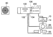
図2は、図1のトラッキング調整用装置10を備えたトラッキング調整システムの一例を示す全体構成図である。
レンズ装置100は、ズームレンズ、フォーカスレンズ、トラッキングレンズなどの光学部材を含んで構成されている。ズームレンズは、焦点距離を変更するために、その光軸方向に移動可能なレンズである。フォーカスレンズは、被写体にピントを合わせるために、その光軸方向に移動可能なレンズである。トラッキングレンズは、結像面の位置を変更するために、その光軸方向に移動可能なレンズである。ズームレンズ及びフォーカスレンズの配置順序は特に限定されないが、トラッキングレンズはフォーカスレンズよりも光軸方向にて後ろ側(カメラ装置200側)に配置されている。
カメラ装置200は、レンズ装置100で結像された被写体像を撮像する撮像素子を含んで構成されている。本例のカメラ装置200は、HD-SDI(High Definition Serial Digital Interface)の映像信号を出力する。
ズームデマンド26は、ズーム位置(ズームレンズの位置)をマニュアルで指示入力するための入力デバイスである。フォーカスデマンド28は、フォーカス位置(フォーカスレンズの位置)をマニュアルで指示入力するための入力デバイスである。レンズ装置100には、ズームデマンド26から出力されるズーム指示信号が入力されるズーム指示信号入力端子102と、フォーカスデマンド28から出力されるフォーカス指示信号が入力されるフォーカス指示信号入力端子104が設けられている。ズーム指示信号は移動先のズーム位置を示し、フォーカス指示信号は移動先のフォーカス位置を示す。また、レンズ装置100には、トラッキングレンズの位置を移動させるためのトラッキング調整ツマミ106が設けられている。つまり、ユーザがトラッキング調整ツマミ106を回すことにより、トラッキングレンズの移動指示がマニュアルで入力される。尚、ズームデマンド26及びフォーカスデマンド28に相当する操作デバイスがレンズ装置100に設けられていてもよい。本発明は、レンズ装置100に操作デバイスが設けられている場合、レンズ装置100に信号入力端子が設けられている場合、及びレンズ装置100に操作デバイス及び信号入力端子の両方が設けられている場合のいずれであってもよい。
トラッキング調整用装置10の映像信号入力端子12には、カメラ装置200からHD-SDIの映像信号が入力される。トラッキング調整用装置10のズーム位置信号入力端子34には、ズームデマンド26からズーム位置信号が入力される。トラッキング調整用装置10のフォーカス位置信号入力端子36には、フォーカスデマンド28からフォーカス位置信号が入力される。
トラッキング調整用装置10は、映像信号入力端子12に入力された映像信号をデコードするデコーダ38と、デコーダ38でデコードされた映像信号をフレーム毎の画像として一時的に記憶する画像メモリ40と、映像信号(画像)から高域の周波数成分(高周波成分)を抽出する高域成分抽出部42と、フォーカスレンズの移動を行う第1のフォーカス調整状態であるか、トラッキングレンズの移動を行う第2のフォーカス調整状態であるかを判定する判定部43と、判定部43の判定結果に基づいて、映像信号(画像)に対してレンズ装置100の焦点状態を検出するための検出エリアを設定するエリア設定部44と、映像信号(画像)の全画面領域のうちエリア設定部44によって設定された検出エリア内で焦点状態を検出して、その焦点状態を示す評価値(フォーカス評価値)を生成する評価値生成部46と、デコーダ38でデコードされた映像信号をモニタ14で表示可能な形式に変換する画像表示回路48を備える。判定部43、エリア設定部44及び評価値生成部46は、例えばCPU(Central Processing Unit)によって構成される。高域成分抽出部42は、例えば回路(又はCPU)によって構成される。
本例の判定部43は、ズームデマンド26によってズームレンズがテレ側の位置(以下単に「テレ」という)に設定されているときにはフォーカスデマンド28によりフォーカスレンズの移動を行う第1のフォーカス調整状態であると判定する。一方、判定部43は、ズームデマンド26によってズームレンズがワイド側の位置(以下単に「ワイド」という)に設定されているときにはトラッキング調整ツマミ106によりトラッキングレンズの移動を行う第2のフォーカス調整状態であると判定する。尚、判定部43の判定態様には各種あり、他の判定態様については後述する。エリア設定部44は、判定部43の判定結果に基づいて、レンズ装置100の焦点状態を検出するための検出エリア(フォーカス評価値の検出エリア)のサイズを切り替える。エリア設定部44は、具体的には、ズーム位置が「ワイド」にある第2のフォーカス調整状態であるときには、ズーム位置が「テレ」にある第1のフォーカス調整状態であるときよりも、フォーカス評価値の検出エリアのサイズを小さくする。尚、「テレ」及び「ワイド」は、ズーム位置の可動範囲の両端である場合には特に限定されないが、ズーム位置の可動範囲の両端で調整を行うことが好ましい。
図2のモニタ14は、図1のインジケータ16を兼ねており、カメラ装置200から取得された映像信号を示す画像と、レンズ装置100の焦点状態を示すグラフとを、同時に表示可能である。また、トラッキング調整用装置10は、フォーカス評価値のマーキング機能を有している。図1の「MARKER」スイッチ24がオンされると、評価値生成部46は、フォーカス位置の変化とフォーカス評価値の変化との関係を図示省略のワークメモリに記録するマーキングを行って、そのマーキング結果を示すグラフをモニタ14に表示させる。さらに、評価値生成部46は、フォーカス評価値のピーク値と、フォーカス評価値がピーク値になるフォーカス位置とを、モニタ14に表示させる。図1の「BEEP」スイッチ22がオンされている場合には、フォーカス評価値がピークとなったときにスピーカ18からビープ音を出力する。また、図1に示すように、モニタ14には画像と共にフォーカス評価値の検出枠82が表示される。本例のモニタ14は、小型の液晶表示ディスプレイ(LCD)によって構成されている。これにより、大型モニタのない現場でも、精密なトラッキング調整を可能にしている。
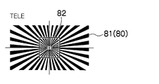
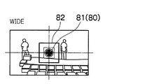
次に、トラッキング調整ツマミ106による第2のフォーカス調整時にフォーカス評価値の検出エリアを小さくする理由について、説明する。図3に示すように、調整用チャート80を被写体としてレンズ装置100を介してカメラ装置200で撮像した場合、フォーカスデマンド28による第1のフォーカス調整時には、ズーム位置が「テレ」であり、図4Aに示すように調整用チャート80の画像81内に検出枠82が入る。このため、調整用チャート80に対する正確なフォーカス評価値が生成される。その一方で、トラッキング調整ツマミ106による第2のフォーカス調整時には、ズーム位置が「ワイド」であり、図4Bに示すように調整用チャート80の画像81内に検出枠82が入らなくなる。このため、調整用チャート80とは距離の異なった被写体(例えば人)の画像が検出枠82内に入り込んでしまう。そこで、図4Cに示すように、第2のフォーカス調整時には、検出枠82のサイズを小さくすることで、検出枠82内に調整用チャート80の画像81以外の他の被写体の画像が入り込まないようにする。
図5は、モニタ14に表示される検出枠の例を示す。図5にて、符号82Tは、ズーム位置が中間~テレ端であるときの検出枠であり、符号82Wは、ズーム位置がワイド端であるときの検出枠である。このように、トラッキング調整用装置10のエリア設定部44は、ズーム位置に応じて、検出枠82のサイズ(検出エリアのサイズ)を切り替える。
図6は、横軸をズーム位置、縦軸を検出枠82のサイズとして、ズーム位置と検出枠82のサイズとの関係の一例を示す。尚、ズーム位置と検出エリアのサイズとの関係は、図6に示した場合には特に限定されない。例えば、ズーム位置が閾値を越えるテレ側の場合には検出エリアのサイズを固定の第1のサイズに設定し、ズーム位置が閾値以下であるワイド側の場合には検出エリアのサイズを第1のサイズよりも小さな固定の第2のサイズに設定するようにしてもよい。
以下では、各種のトラッキング調整例について、説明する。
図7は、第1実施例のトラッキング調整処理の流れを示すフローチャートである。本処理は、トラッキング調整用装置10の判定部43、エリア設定部44及び評価値生成部46を構成するCPUによって、プログラムに従って実行される。本例では、図2に示したように、ズーム位置信号入力端子34にズーム位置信号が入力される。本例の判定部43は、入力されたズーム位置信号に基づいて調整状態の判定を行う。
図7において、まず、トラッキング調整の判断以外の処理を実行する(ステップS102)。
続いて、手動設定操作の有無を判定する(ステップS104)。
図8に示すように、本例ではモニタ14がタッチパネル15によって構成されている。ズーム位置を入力するための手動スイッチとして「T」スイッチ84T及び「W」スイッチ84Wがタッチパネル15に表示される。「T」スイッチ84Tにタッチすると、ズーム位置として「テレ」が入力される。「W」スイッチ84Wにタッチすると、ズーム位置として「ワイド」が入力される。
手動設定操作有りの場合には、手動スイッチを読み込む(ステップS106)。手動設定操作無しの場合には、ズーム位置信号入力端子34に入力されているズーム位置信号を読み込む(ステップS108)。
続いて、判定部43によって、ズーム位置が「テレ」であるか否かを判定することにより、フォーカスデマンド28によりフォーカス調整を行う状態であるか、トラッキング調整ツマミ106によりフォーカス調整を行う状態であるかを判定する(ステップS110)。即ち、判定部43は、ズーム位置信号または手動スイッチに基づいて、第1のフォーカス調整状態であるか第2のフォーカス調整状態であるかを判定する。
ズーム位置が「テレ」である場合、エリア設定部44はフォーカス評価値の検出枠を大サイズに設定し(ステップS112)、図9に示すように、評価値生成部46はグラフ形状を折れ線に設定してグラフを生成する(ステップS114)。図9のグラフは、フォーカス位置信号入力端子36に入力されたフォーカス位置信号に基づいて、評価値生成部46で生成されたものである。このグラフは、フォーカス位置の変化に対する検出枠82内のフォーカス評価値の変化を示すと共に、フォーカス評価値の極大値83Vと、フォーカス評価値が極大値83Vとなったフォーカス位置83Pを示す。
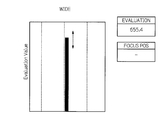
ズーム位置が「ワイド」である場合、エリア設定部44はフォーカス評価値の検出枠を小サイズに設定し(ステップS116)、図10に示すように、評価値生成部46はグラフ形状をバーに設定してグラフを生成する(ステップS118)。このグラフは、トラッキングレンズの位置(トラッキング位置)の変化に応じて、フォーカス評価値が上下に変化するバー形状のグラフである。即ち、トラッキングレンズの現在位置に対応するフォーカス評価値をリアルタイムに示す。尚、図10には縦形状のバーを示したが、横形状のバーでもよい。
生成されたグラフはモニタ14に表示される(ステップS120)。
以上のように、「テレ」で行う第1のフォーカス調整と「ワイド」で行う第2のフォーカス調整とで、フォーカス評価値の検出エリアのサイズ(検出枠82のサイズ)が切り替わるので、フォーカスレンズを移動させる第1のフォーカス調整時でもトラッキングレンズを移動させる第2のフォーカス調整時でも、同様の精度でフォーカス評価値が生成される。また、「テレ」でフォーカス位置を変化させてマーキングを行うときには図9に示す折れ線形状のグラフが自動的に表示され、「ワイド」でトラッキング位置を調整するときには図10に示すバー形状のグラフに自動的に切り替わるので、トラッキング調整を容易且つ短時間で完了させることが可能になる。
尚、図2には、ズームデマンド26及びフォーカスデマンド28からトラッキング調整用装置10に信号が入力される場合を例に示したが、本発明はこのような場合に限定されない。例えば、レンズ装置100からトラッキング調整用装置10にズーム位置信号及びフォーカス位置信号が入力されてもよい。
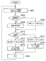
図11は、第2実施例のトラッキング調整処理の流れを示すフローチャートである。本処理は、トラッキング調整用装置10のCPUによって、プログラムに従って実行される。
ステップS202~S206は、図7に示した第1実施例のステップS102~S106と同様であり、ここでは説明を省略する。
図11に示す第2実施例では、手動設定操作無し(ステップS204でNO)の場合、カメラ装置200から取得された映像信号に基づいて、画像処理により、テレ側での調整であるか否かを判定する(ステップS208)。
図12Aは、ズーム位置が「テレ」である場合にカメラ装置200によって図3の調整用チャート80を撮像して得られた画像(以下「テレ画像」という)の一例を示す。図12Bは、ズーム位置が「ワイド」である場合にカメラ装置200によって図3の調整用チャート80を撮像して得られた画像(以下「ワイド画像」という)の一例を示す。
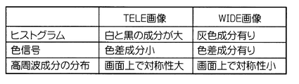
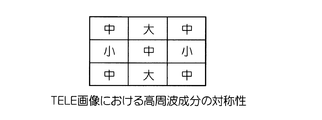
図12Aのテレ画像と図12Bのワイド画像とでは、図13Aに示すように、色分布のヒストグラム、色信号(輝度+色差信号)、高周波成分の画面上の分布などにおいて、顕著な差異がある。図3の調整用チャート80は白及び黒色の放射状の縞模様である。このため、色分布のヒストグラムについては、テレ画像では白及び黒の両方の成分の頻度が他の色の成分の頻度よりも顕著に大きくなり、ワイド画像ではテレ画像よりも灰色成分の頻度が大きくなる。また、色信号については、テレ画像では色差成分が小さくなり、ワイド画像では色差成分が大きくなる。また、高周波成分の画面上の分布については、図13Bに示すように、テレ画像では高周波成分の対称性が大きくなり、ワイド画像では対称性が小さくなる。
本例のトラッキング調整用装置10の判定部43は、カメラ装置200から取得した映像信号に基づいて、ズーム位置が「テレ」であるか否かを判定する。例えば、色分布のヒストグラム、色信号の色差、及び高周波成分の画面上の分布のうち少なくともひとつに基づいて、「テレ」であるか「ワイド」であるかを判定する。
例えば、レンズ装置100の判定部43は、色分布のヒストグラムのうち白及び黒の両方で頻度が閾値を超える場合に、ズーム位置が「テレ」であると判定する。
また、例えば、レンズ装置100の判定部43は、高周波成分が画面上で放射状の対称性を有するか否かを判定し、放射状の対称性を有する場合には、ズーム位置が「テレ」であると判定する。
これにより、手動操作で設定しなくても、また、ズーム位置信号を取得できない環境であっても、第1のフォーカス調整状態であるか第2のフォーカス調整状態であるかを的確に判定することが可能になる。
ステップS210~S220は、図7に示した第1実施例のステップS110~S120とそれぞれ同様であり、ここでは説明を省略する。
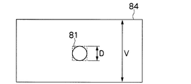
調整用チャート80を撮像している様子を図14Aに示し、映像信号の全画面領域84(画面)内における調整用チャート80の画像81を図14Bに示す。
図14Aにおいて、調整用チャート80までの距離Lは、レンズ緒元や実際の撮影距離により任意であるが、例えば2~6mである。ただし、長焦点型のズームレンズは、MOD(最至近撮影距離)が3m程度のものが多く、それ以上の距離に設定される。
フォーカス評価値の検出枠のサイズは、エリア設定部44によって、全画面領域84のサイズと調整用チャート80の画像81のサイズとの比(本例ではD/V)に比例した値に決定される。エリア設定部44は、映像信号から調整用チャート80の画像81を抽出し、抽出した画像のサイズDに応じて検出枠82のサイズ(検出エリアのサイズ)を切り替える。
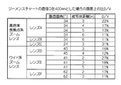
調整用チャート80の画像81のサイズDと画面サイズVとの比D/Vの例を、図15に示す。調整用チャート80としてのジーメンスチャートの直径(図14AのD)を400mmとした場合、本例のレンズ装置100では、図15に示すように、ワイド端でD/Vが11%~31%であった。したがって、ワイド端におけるフォーカス評価値の検出エリアは、例えば画面高さの10%、20%、30%の長さの辺からなる正方形から選択する。10~30%の範囲で調整可能にしてもよい。
図16A及び図16Bは、トラッキング調整用装置10における画面の例を示す。本例では、タッチパネル15によってモニタ14が構成されている。タッチパネル15上の表示モード切替スイッチ86A、86Bにタッチすると、表示モードが切り替わる。
図16Aに示すバックフォーカス調整(BF ADJ)モードでは、カメラ装置200から取得した映像信号を示す撮像画像87、グラフ88、「T」スイッチ84T,「W」スイッチ84W、及び、AF(Automatic Focus)枠追尾モードに切り替えるための表示モード切替スイッチ86Aが表示される。「T」スイッチ84T、「W」スイッチ84Wは、図10に示したものと同じである。本例でも、タッチ操作を受け付けることで、ズーム位置を取得する。
図16Bに示すAF枠追尾モードでは、カメラ装置200から取得した映像信号を示す撮像画像87に、検出枠82が重ね合わされて、表示される。トラッキング調整用装置10のCPUは、主要被写体を追尾し、検出枠82も追尾させる。
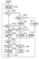
図17は、第3実施例のトラッキング調整処理例の流れを示すフローチャートである。本処理は、トラッキング調整用装置10のCPUによって、プログラムに従って実行される。
まず、トラッキング調整の判断以外の処理を実行する(ステップS302)。
続いて、スイッチ操作の有無を判定する(ステップS304)。本例では、図16Aに示した、「T」スイッチ84T、「W」スイッチ84W、及び「AUTO」スイッチ85が操作されたかどうかを判定する。
スイッチ操作有りの場合には、テレ/ワイド自動設定を指示入力するための「AUTO」スイッチ85が操作されたか否かを判定する(ステップS306)。
AUTOスイッチ85の操作でない場合(「T」スイッチ84Tまたは「W」スイッチ84Wの操作である場合)、T/W手動設定フラグをオンし(ステップS308)、直前の操作が「T」スイッチ84Tの操作であったか否かを判定する(ステップS310)。そして、「T」スイッチ84Tの操作であった場合にはズーム位置情報を「テレ」に設定し(ステップS312)、直前の操作が「W」スイッチ84Wの操作であった場合にはズーム位置情報を「ワイド」に設定する(ステップS314)。
「AUTO」スイッチが操作された場合には、T/W手動設定フラグをオフする(ステップS316)。
スイッチ操作無しの場合には、T/W手動設定フラグがオンであるか否かを判定する(ステップS318)。ここで、T/W手動設定フラグがオンである場合には、ステップS310に進む。T/W手動設定フラグがオフである場合(テレ/ワイド自動設定の場合)には、ズーム位置信号入力端子34からズーム位置信号を読み込んで(ステップS320)、そのズーム位置信号に応じでズーム位置情報を設定する(ステップS322)。即ち、「AUTO」スイッチ85が操作されていた場合には、ズーム位置信号に応じて自動的にテレ/ワイドが設定される。
ステップS324~S334は、図7のステップS110~S120とそれぞれ同様であり、ここでは説明を省略する。
尚、トラッキング調整用装置10は、専用のハードウェアではなく、コンピュータ装置によって構成してもよい。その場合、プログラムに従って、本明細書に記載のトラッキング調整方法をコンピュータ装置に実行させればよい。また、本発明は、デバイスに上記の処理を行わせるためのコンピュータ読取可能なプログラムコード、該プログラムコードが格納される非一次的(non-transitory)かつコンピュータ読取可能な記録媒体(例えば、光ディスク(例えば、CD(Compact Disc)、DVD(Digital Versatile Disc)、BD(Blu-ray Disc))、磁気ディスク(例えば、ハードディスク、光磁気ディスク))、及び該方法のための実行可能なコードを格納するコンピューター・プログラム・プロダクトとして提供することができる。
本発明は、本明細書において説明した例や図面に図示された例には限定されず、本発明の要旨を逸脱しない範囲において、各種の設計変更や改良を行ってよいのはもちろんである。
本明細書は、以下の発明を開示している。
(発明1)焦点距離を変更するために移動可能なズームレンズの移動指示が入力されるズーム指示入力手段、被写体にピントを合わせるために移動可能なフォーカスレンズの移動指示が入力されるフォーカス指示入力手段、及び、結像面の位置を変更するために移動可能なトラッキングレンズの移動指示が入力されるトラッキング指示入力手段を備えたトラッキング調整用装置であって、ズームレンズ、フォーカスレンズ及びトラッキングレンズを有するレンズ装置が装着されたカメラ装置から映像信号を取得する映像信号取得手段と、ズーム指示入力手段によってズームレンズがテレ側の位置に設定されてフォーカス指示入力手段によってフォーカスレンズの移動が行われる第1の調整状態であるか、ズーム指示入力手段によってズームレンズがワイド側の位置に設定されてトラッキング指示入力手段によってトラッキングレンズの移動が行われる第2の調整状態であるかを判定する判定手段と、映像信号取得手段によって取得された映像信号に対してレンズ装置の焦点状態を検出するための検出エリアを設定するエリア設定手段であって、判定手段の判定結果に基づいて第1の調整状態と第2の調整状態とで検出エリアのサイズを切り替えるエリア設定手段と、映像信号取得手段によって取得された映像信号からレンズ装置の焦点状態を示す評価値を生成する評価値生成手段であって、映像信号の全画面領域のうちでエリア設定手段によって設定された検出エリア内で評価値を生成する評価値生成手段と、評価値生成手段によって生成された評価値を表示する表示手段と、を備えたトラッキング調整用装置。
(発明2)エリア設定手段は、第2の調整状態であるときには、第1の調整状態であるときよりも、検出エリアのサイズを小さくする発明1に記載のトラッキング調整用装置。
(発明3)判定手段は、カメラ装置から取得された映像信号に基づいて、第1の調整状態であるか第2の調整状態であるかを判定する発明1または2に記載のトラッキング調整用装置。
(発明4)判定手段は、ズーム指示入力手段及びレンズ装置のうち一方から出力されるズームレンズの位置を示すズーム位置信号に基づいて、第1の調整状態であるか第2の調整状態であるかを判定する発明1または2に記載のトラッキング調整用装置。
(発明5)判定手段は、ユーザの入力操作に基づいて、第1の調整状態であるか第2の調整状態であるかを判定する発明1または2に記載のトラッキング調整用装置。
(発明6)エリア設定手段は、映像信号から特定の静止物体の画像を抽出し、抽出した画像のサイズに応じて検出エリアのサイズを切り替える発明1から5のうちいずれかひとつに記載のトラッキング調整用装置。
(発明7)評価値生成手段は、第1の調整状態の時と第2の調整状態の時とで異なる形式のグラフを生成し、表示手段は、評価値生成手段によって生成されたグラフを表示する発明1から6のうちいずれかひとつに記載のトラッキング調整用装置。
(発明8)評価値生成手段は、第1の調整状態であるときには、フォーカスレンズの位置の変化に対する焦点状態の評価値の変化を示す第1のグラフを生成し、第2の調整状態であるときには、トラッキングレンズの現在位置に対応する焦点状態の評価値を示すバー形状の第2のグラフを生成する発明7に記載のトラッキング調整用装置。
(発明9)焦点距離を変更するために移動可能なズームレンズの移動指示が入力されるズーム指示入力手段、被写体にピントを合わせるために移動可能なフォーカスレンズの移動指示が入力されるフォーカス指示入力手段、及び、結像面の位置を変更するために移動可能なトラッキングレンズの移動指示が入力されるトラッキング指示入力手段を用いるトラッキング調整方法であって、ズーム指示入力手段によってズームレンズがテレ側の位置に設定されてフォーカス指示入力手段によってフォーカスレンズの移動が行われる第1の調整状態であるか、ズーム指示入力手段によってズームレンズがワイド側の位置に設定されてトラッキング指示入力手段によってトラッキングレンズの移動が行われる第2の調整状態であるかを判定する判定ステップと、ズームレンズ、フォーカスレンズ及びトラッキングレンズを有するレンズ装置が装着されたカメラ装置から取得された映像信号に対して、レンズ装置の焦点状態を検出するための検出エリアを設定するエリア設定ステップであって、判定ステップの判定結果に基づいて第1の調整状態と第2の調整状態とで検出エリアのサイズを切り替えるエリア設定ステップと、取得された映像信号からレンズ装置の焦点状態を示す評価値を生成する評価値生成ステップであって、映像信号の全画面領域のうちでエリア設定ステップによって設定された検出エリア内で評価値を生成する評価値生成ステップと、評価値生成ステップによって生成された評価値を表示する表示ステップと、を備えたトラッキング調整方法。
(発明10)エリア設定ステップは、第2の調整状態であるときには、第1の調整状態であるときよりも、検出エリアのサイズを小さくする発明9に記載のトラッキング調整方法。
(発明11)判定ステップは、カメラ装置から取得された映像信号に基づいて、第1の調整状態であるか第2の調整状態であるかを判定する発明9または10に記載のトラッキング調整方法。
(発明12)判定ステップは、ズーム指示入力手段及びレンズ装置のうち一方から出力されるズームレンズの位置を示すズーム位置信号に基づいて、第1の調整状態であるか第2の調整状態であるかを判定する発明9または10に記載のトラッキング調整方法。
(発明13)判定ステップは、ユーザの入力操作に基づいて、第1の調整状態であるか第2の調整状態であるかを判定する発明9または10に記載のトラッキング調整方法。
(発明14)エリア設定ステップは、映像信号から特定の静止物体の画像を抽出し、抽出した画像のサイズに応じて検出エリアのサイズを切り替える発明9から13のうちいずれかひとつに記載のトラッキング調整方法。
(発明15)評価値生成ステップは、第1の調整状態の時と第2の調整状態の時とで異なる形式のグラフを生成し、表示ステップは、評価値生成ステップによって生成されたグラフを表示する発明9から14のうちいずれかひとつに記載のトラッキング調整方法。
(発明16)評価値生成ステップは、第1の調整状態であるときには、フォーカスレンズの位置の変化に対して焦点状態を示す評価値が極大になったフォーカスレンズの位置を示す第1のグラフを生成し、第2の調整状態であるときには、トラッキングレンズの位置の変化に応じて焦点状態を示す評価値が変化するバー形状の第2のグラフを生成する発明15に記載のトラッキング調整方法。
(発明17)発明9から16のうちいずれかひとつに記載のトラッキング調整方法をコンピュータ装置に実行させるプログラム。このプログラムは所定の記録媒体に記録して提供される。
10:トラッキング調整用装置、12:トラッキング調整用装置の映像信号入力端子、14:モニタ、26:ズームデマンド、34:フォーカスデマンド28:トラッキング調整用装置のズーム位置信号入力端子、36:トラッキング調整用装置のフォーカス位置信号入力端子、42:高域成分抽出部、43:判定部、44:エリア設定部、46:評価値生成部、48:画像表示回路、80:調整用チャート(静止物体)、82:検出枠、84T:Tスイッチ、84W:Wスイッチ、100:レンズ装置、102:レンズ装置のズーム指示信号入力端子(ズーム指示入力手段)、104:レンズ装置のフォーカス指示信号入力端子(フォーカス指示入力手段)、110:バックフォーカス調整ツマミ(トラッキング指示入力手段)、200:カメラ装置
Claims (17)
- 焦点距離を変更するために移動可能なズームレンズの移動指示が入力されるズーム指示入力手段と、
被写体にピントを合わせるために移動可能なフォーカスレンズの移動指示が入力されるフォーカス指示入力手段と、
結像面の位置を変更するために移動可能なトラッキングレンズの移動指示が入力されるトラッキング指示入力手段と、
前記ズームレンズ、前記フォーカスレンズ及び前記トラッキングレンズを有するレンズ装置が装着されたカメラ装置から映像信号を取得する映像信号取得手段と、
前記ズーム指示入力手段によって前記ズームレンズがテレ側の位置に設定されて前記フォーカス指示入力手段によって前記フォーカスレンズの移動が行われる第1の調整状態であるか、前記ズーム指示入力手段によって前記ズームレンズがワイド側の位置に設定されて前記トラッキング指示入力手段によって前記トラッキングレンズの移動が行われる第2の調整状態であるかを判定する判定手段と、
前記映像信号取得手段によって取得された映像信号に対して前記レンズ装置の焦点状態を検出するための検出エリアを設定するエリア設定手段であって、前記判定手段の判定結果に基づいて前記第1の調整状態と前記第2の調整状態とで前記検出エリアのサイズを切り替えるエリア設定手段と、
前記映像信号取得手段によって取得された映像信号から前記レンズ装置の焦点状態を示す評価値を生成する評価値生成手段であって、前記映像信号の全画面領域のうちで前記エリア設定手段によって設定された検出エリア内で前記評価値を生成する評価値生成手段と、
前記評価値生成手段によって生成された評価値を表示する表示手段と、
を備えたトラッキング調整用装置。 - 前記エリア設定手段は、前記第2の調整状態であるときには、前記第1の調整状態であるときよりも、前記検出エリアのサイズを小さくする請求項1に記載のトラッキング調整用装置。
- 前記判定手段は、前記カメラ装置から取得された映像信号に基づいて、前記第1の調整状態であるか前記第2の調整状態であるかを判定する請求項1または2に記載のトラッキング調整用装置。
- 前記判定手段は、前記ズーム指示入力手段及び前記レンズ装置のうち一方から出力される前記ズームレンズの位置を示すズーム位置信号に基づいて、前記第1の調整状態であるか前記第2の調整状態であるかを判定する請求項1または2に記載のトラッキング調整用装置。
- 前記判定手段は、ユーザの入力操作に基づいて、前記第1の調整状態であるか前記第2の調整状態であるかを判定する請求項1または2に記載のトラッキング調整用装置。
- 前記エリア設定手段は、前記映像信号から特定の静止物体の画像を抽出し、前記抽出した画像のサイズに応じて前記検出エリアのサイズを切り替える請求項1から5のうちいずれか1項に記載のトラッキング調整用装置。
- 前記評価値生成手段は、前記第1の調整状態のときと前記第2の調整状態のときとで異なる形式のグラフを生成し、
前記表示手段は、前記評価値生成手段によって生成されたグラフを表示する請求項1から6のうちいずれか1項に記載のトラッキング調整用装置。 - 前記評価値生成手段は、前記第1の調整状態であるときには、前記フォーカスレンズの位置の変化に対する前記焦点状態の評価値の変化を示す第1のグラフを生成し、前記第2の調整状態であるときには、前記トラッキングレンズの現在位置に対応する前記焦点状態の評価値を示すバー形状の第2のグラフを生成する請求項7に記載のトラッキング調整用装置。
- 焦点距離を変更するために移動可能なズームレンズの移動指示が入力されるズーム指示入力手段、被写体にピントを合わせるために移動可能なフォーカスレンズの移動指示が入力されるフォーカス指示入力手段、及び、結像面の位置を変更するために移動可能なトラッキングレンズの移動指示が入力されるトラッキング指示入力手段を用いるトラッキング調整方法であって、
前記ズーム指示入力手段によって前記ズームレンズがテレ側の位置に設定されて前記フォーカス指示入力手段によって前記フォーカスレンズの移動が行われる第1の調整状態であるか、前記ズーム指示入力手段によって前記ズームレンズがワイド側の位置に設定されて前記トラッキング指示入力手段によって前記トラッキングレンズの移動が行われる第2の調整状態であるかを判定する判定ステップと、
前記ズームレンズ、前記フォーカスレンズ及び前記トラッキングレンズを有するレンズ装置が装着されたカメラ装置から取得された映像信号に対して、前記レンズ装置の焦点状態を検出するための検出エリアを設定するエリア設定ステップであって、前記判定ステップの判定結果に基づいて前記第1の調整状態と前記第2の調整状態とで前記検出エリアのサイズを切り替えるエリア設定ステップと、
前記取得された映像信号から前記レンズ装置の焦点状態を示す評価値を生成する評価値生成ステップであって、前記映像信号の全画面領域のうちで前記エリア設定ステップによって設定された検出エリア内で前記評価値を生成する評価値生成ステップと、
前記評価値生成ステップによって生成された評価値を表示する表示ステップと、
を備えたトラッキング調整方法。 - 前記エリア設定ステップは、前記第2の調整状態であるときには、前記第1の調整状態であるときよりも、前記検出エリアのサイズを小さくする請求項9に記載のトラッキング調整方法。
- 前記判定ステップは、前記カメラ装置から取得された映像信号に基づいて、前記第1の調整状態であるか前記第2の調整状態であるかを判定する請求項9または10に記載のトラッキング調整方法。
- 前記判定ステップは、前記ズーム指示入力手段及び前記レンズ装置のうち一方から出力される前記ズームレンズの位置を示すズーム位置信号に基づいて、前記第1の調整状態であるか前記第2の調整状態であるかを判定する請求項9または10に記載のトラッキング調整方法。
- 前記判定ステップは、ユーザの入力操作に基づいて、前記第1の調整状態であるか前記第2の調整状態であるかを判定する請求項9または10に記載のトラッキング調整方法。
- 前記エリア設定ステップは、前記映像信号から特定の静止物体の画像を抽出し、前記抽出した画像のサイズに応じて前記検出エリアのサイズを切り替える請求項9から13のうちいずれか1項に記載のトラッキング調整方法。
- 前記評価値生成ステップは、前記第1の調整状態のときと前記第2の調整状態のときとで異なる形式のグラフを生成し、
前記表示ステップは、前記評価値生成ステップによって生成されたグラフを表示する請求項9から14のうちいずれか1項に記載のトラッキング調整方法。 - 前記評価値生成ステップは、前記第1の調整状態であるときには、前記フォーカスレンズの位置の変化に対する前記焦点状態の評価値の変化を示す第1のグラフを生成し、前記第2の調整状態であるときには、前記トラッキングレンズの現在位置に対応する前記焦点状態の評価値を示すバー形状の第2のグラフを生成する請求項15に記載のトラッキング調整方法。
- 請求項9から16のうちいずれか1項に記載のトラッキング調整方法をコンピュータ装置に実行させるプログラム。
Priority Applications (2)
| Application Number | Priority Date | Filing Date | Title |
|---|---|---|---|
| EP13809113.7A EP2866068B1 (en) | 2012-06-25 | 2013-06-24 | Device for tracking adjustment, tracking adjustment method and program |
| US14/577,594 US9304183B2 (en) | 2012-06-25 | 2014-12-19 | Device for tracking adjustment and tracking adjustment method |
Applications Claiming Priority (2)
| Application Number | Priority Date | Filing Date | Title |
|---|---|---|---|
| JP2012-142329 | 2012-06-25 | ||
| JP2012142329A JP5939904B2 (ja) | 2012-06-25 | 2012-06-25 | トラッキング調整用装置、トラッキング調整方法及びプログラム |
Related Child Applications (1)
| Application Number | Title | Priority Date | Filing Date |
|---|---|---|---|
| US14/577,594 Continuation US9304183B2 (en) | 2012-06-25 | 2014-12-19 | Device for tracking adjustment and tracking adjustment method |
Publications (1)
| Publication Number | Publication Date |
|---|---|
| WO2014002928A1 true WO2014002928A1 (ja) | 2014-01-03 |
Family
ID=49783075
Family Applications (1)
| Application Number | Title | Priority Date | Filing Date |
|---|---|---|---|
| PCT/JP2013/067191 Ceased WO2014002928A1 (ja) | 2012-06-25 | 2013-06-24 | トラッキング調整用装置、トラッキング調整方法及びプログラム |
Country Status (4)
| Country | Link |
|---|---|
| US (1) | US9304183B2 (ja) |
| EP (1) | EP2866068B1 (ja) |
| JP (1) | JP5939904B2 (ja) |
| WO (1) | WO2014002928A1 (ja) |
Families Citing this family (6)
| Publication number | Priority date | Publication date | Assignee | Title |
|---|---|---|---|---|
| JP6438276B2 (ja) * | 2014-11-04 | 2018-12-12 | オリンパス株式会社 | 顕微鏡システム |
| CN105847670B (zh) * | 2015-02-04 | 2019-06-21 | 佳能株式会社 | 电子设备、摄像控制装置及其控制方法 |
| KR102214094B1 (ko) | 2017-03-21 | 2021-02-09 | 한화테크윈 주식회사 | 줌 트래킹 방법 및 줌 카메라 |
| JP6918605B2 (ja) * | 2017-06-29 | 2021-08-11 | キヤノン株式会社 | 撮像制御装置、制御方法、プログラム、及び記憶媒体 |
| JP7584907B2 (ja) * | 2020-05-12 | 2024-11-18 | キヤノン株式会社 | 撮像装置および撮像装置の制御方法 |
| JP7642327B2 (ja) * | 2020-06-22 | 2025-03-10 | キヤノン株式会社 | 撮像制御装置、撮像システム、撮像装置の制御方法、およびプログラム |
Citations (8)
| Publication number | Priority date | Publication date | Assignee | Title |
|---|---|---|---|---|
| JP2003029137A (ja) * | 2001-07-18 | 2003-01-29 | Olympus Optical Co Ltd | 自動焦点検出装置 |
| JP2004207774A (ja) * | 2002-02-22 | 2004-07-22 | Fuji Photo Film Co Ltd | デジタルカメラ |
| JP2004258087A (ja) * | 2003-02-24 | 2004-09-16 | Fuji Photo Optical Co Ltd | オートフォーカスシステム |
| JP2004280048A (ja) | 2003-02-24 | 2004-10-07 | Fuji Photo Optical Co Ltd | レンズ制御システム及びカメラ装置 |
| JP2005043410A (ja) * | 2003-07-22 | 2005-02-17 | Fujinon Corp | 撮影レンズのオートトラッキング調整システム |
| JP2005140943A (ja) | 2003-11-06 | 2005-06-02 | Canon Inc | フォーカスアシスト装置、ドライブユニット、撮影レンズおよび撮影システム |
| JP2007295240A (ja) | 2006-04-25 | 2007-11-08 | Canon Inc | 撮像装置 |
| JP2013140288A (ja) * | 2012-01-06 | 2013-07-18 | Canon Inc | 焦点調節装置 |
Family Cites Families (1)
| Publication number | Priority date | Publication date | Assignee | Title |
|---|---|---|---|---|
| US20040036792A1 (en) * | 2002-08-23 | 2004-02-26 | Chikatsu Moriya | Camera system and focus information display apparatus |
-
2012
- 2012-06-25 JP JP2012142329A patent/JP5939904B2/ja active Active
-
2013
- 2013-06-24 WO PCT/JP2013/067191 patent/WO2014002928A1/ja not_active Ceased
- 2013-06-24 EP EP13809113.7A patent/EP2866068B1/en active Active
-
2014
- 2014-12-19 US US14/577,594 patent/US9304183B2/en active Active
Patent Citations (8)
| Publication number | Priority date | Publication date | Assignee | Title |
|---|---|---|---|---|
| JP2003029137A (ja) * | 2001-07-18 | 2003-01-29 | Olympus Optical Co Ltd | 自動焦点検出装置 |
| JP2004207774A (ja) * | 2002-02-22 | 2004-07-22 | Fuji Photo Film Co Ltd | デジタルカメラ |
| JP2004258087A (ja) * | 2003-02-24 | 2004-09-16 | Fuji Photo Optical Co Ltd | オートフォーカスシステム |
| JP2004280048A (ja) | 2003-02-24 | 2004-10-07 | Fuji Photo Optical Co Ltd | レンズ制御システム及びカメラ装置 |
| JP2005043410A (ja) * | 2003-07-22 | 2005-02-17 | Fujinon Corp | 撮影レンズのオートトラッキング調整システム |
| JP2005140943A (ja) | 2003-11-06 | 2005-06-02 | Canon Inc | フォーカスアシスト装置、ドライブユニット、撮影レンズおよび撮影システム |
| JP2007295240A (ja) | 2006-04-25 | 2007-11-08 | Canon Inc | 撮像装置 |
| JP2013140288A (ja) * | 2012-01-06 | 2013-07-18 | Canon Inc | 焦点調節装置 |
Non-Patent Citations (1)
| Title |
|---|
| See also references of EP2866068A4 |
Also Published As
| Publication number | Publication date |
|---|---|
| EP2866068B1 (en) | 2017-01-25 |
| US20150103185A1 (en) | 2015-04-16 |
| JP2014006398A (ja) | 2014-01-16 |
| EP2866068A4 (en) | 2016-01-20 |
| EP2866068A1 (en) | 2015-04-29 |
| JP5939904B2 (ja) | 2016-06-22 |
| US9304183B2 (en) | 2016-04-05 |
Similar Documents
| Publication | Publication Date | Title |
|---|---|---|
| CN103973973B (zh) | 摄像装置 | |
| JP5939904B2 (ja) | トラッキング調整用装置、トラッキング調整方法及びプログラム | |
| JP2014222801A5 (ja) | ||
| JP2010093422A (ja) | 撮像装置 | |
| JP6202910B2 (ja) | 映像処理装置およびその制御方法、プログラム | |
| JP2015194672A (ja) | 撮像装置 | |
| JP2018066845A (ja) | 顕微鏡システム | |
| CN102483324A (zh) | 拍摄装置及其控制方法,以及三维信息测量装置 | |
| JP2014123069A (ja) | 撮像装置及びその制御方法 | |
| JP6357646B2 (ja) | 撮像装置 | |
| JP2008281385A (ja) | 画像処理装置 | |
| TW202002606A (zh) | 影像擷取裝置與其操作方法 | |
| JP2015194680A (ja) | 撮像装置 | |
| JP6404482B2 (ja) | 測距装置、測距用制御方法、及び測距用制御プログラム | |
| EP3933474B1 (en) | Image processing device, image processing method, program, and imaging device | |
| JP6404483B2 (ja) | 測距装置、測距用制御方法、及び測距用制御プログラム | |
| CN113965704A (zh) | 控制设备、控制方法和程序 | |
| JP2008113466A5 (ja) | ||
| JP2016036183A (ja) | 撮像装置 | |
| JP5395503B2 (ja) | 表示制御装置およびその動作制御方法 | |
| JP2016167721A (ja) | 撮像装置 | |
| JP6089232B2 (ja) | 撮像装置 | |
| JP6377225B2 (ja) | 画像処理装置およびその制御方法、プログラム | |
| JP2016045350A (ja) | レンズ鏡筒および撮像装置、被写体距離の表示方法、並びにプログラム | |
| JP2024522409A (ja) | 撮像装置およびフォーカス制御プログラム |
Legal Events
| Date | Code | Title | Description |
|---|---|---|---|
| 121 | Ep: the epo has been informed by wipo that ep was designated in this application |
Ref document number: 13809113 Country of ref document: EP Kind code of ref document: A1 |
|
| REEP | Request for entry into the european phase |
Ref document number: 2013809113 Country of ref document: EP |
|
| WWE | Wipo information: entry into national phase |
Ref document number: 2013809113 Country of ref document: EP |
|
| NENP | Non-entry into the national phase |
Ref country code: DE |