WO2014003149A1 - 取付板付き転がり軸受ユニットおよびその製造方法 - Google Patents
取付板付き転がり軸受ユニットおよびその製造方法 Download PDFInfo
- Publication number
- WO2014003149A1 WO2014003149A1 PCT/JP2013/067737 JP2013067737W WO2014003149A1 WO 2014003149 A1 WO2014003149 A1 WO 2014003149A1 JP 2013067737 W JP2013067737 W JP 2013067737W WO 2014003149 A1 WO2014003149 A1 WO 2014003149A1
- Authority
- WO
- WIPO (PCT)
- Prior art keywords
- mounting plate
- diameter
- outer ring
- rolling bearing
- bearing unit
- Prior art date
- Legal status (The legal status is an assumption and is not a legal conclusion. Google has not performed a legal analysis and makes no representation as to the accuracy of the status listed.)
- Ceased
Links
Images





Classifications
-
- F—MECHANICAL ENGINEERING; LIGHTING; HEATING; WEAPONS; BLASTING
- F16—ENGINEERING ELEMENTS AND UNITS; GENERAL MEASURES FOR PRODUCING AND MAINTAINING EFFECTIVE FUNCTIONING OF MACHINES OR INSTALLATIONS; THERMAL INSULATION IN GENERAL
- F16C—SHAFTS; FLEXIBLE SHAFTS; ELEMENTS OR CRANKSHAFT MECHANISMS; ROTARY BODIES OTHER THAN GEARING ELEMENTS; BEARINGS
- F16C19/00—Bearings with rolling contact, for exclusively rotary movement
- F16C19/02—Bearings with rolling contact, for exclusively rotary movement with bearing balls essentially of the same size in one or more circular rows
- F16C19/04—Bearings with rolling contact, for exclusively rotary movement with bearing balls essentially of the same size in one or more circular rows for radial load mainly
- F16C19/06—Bearings with rolling contact, for exclusively rotary movement with bearing balls essentially of the same size in one or more circular rows for radial load mainly with a single row or balls
-
- F—MECHANICAL ENGINEERING; LIGHTING; HEATING; WEAPONS; BLASTING
- F16—ENGINEERING ELEMENTS AND UNITS; GENERAL MEASURES FOR PRODUCING AND MAINTAINING EFFECTIVE FUNCTIONING OF MACHINES OR INSTALLATIONS; THERMAL INSULATION IN GENERAL
- F16C—SHAFTS; FLEXIBLE SHAFTS; ELEMENTS OR CRANKSHAFT MECHANISMS; ROTARY BODIES OTHER THAN GEARING ELEMENTS; BEARINGS
- F16C35/00—Rigid support of bearing units; Housings, e.g. caps, covers
- F16C35/04—Rigid support of bearing units; Housings, e.g. caps, covers in the case of ball or roller bearings
- F16C35/06—Mounting or dismounting of ball or roller bearings; Fixing them onto shaft or in housing
- F16C35/067—Fixing them in a housing
-
- F—MECHANICAL ENGINEERING; LIGHTING; HEATING; WEAPONS; BLASTING
- F16—ENGINEERING ELEMENTS AND UNITS; GENERAL MEASURES FOR PRODUCING AND MAINTAINING EFFECTIVE FUNCTIONING OF MACHINES OR INSTALLATIONS; THERMAL INSULATION IN GENERAL
- F16C—SHAFTS; FLEXIBLE SHAFTS; ELEMENTS OR CRANKSHAFT MECHANISMS; ROTARY BODIES OTHER THAN GEARING ELEMENTS; BEARINGS
- F16C19/00—Bearings with rolling contact, for exclusively rotary movement
- F16C19/54—Systems consisting of a plurality of bearings with rolling friction
-
- F—MECHANICAL ENGINEERING; LIGHTING; HEATING; WEAPONS; BLASTING
- F16—ENGINEERING ELEMENTS AND UNITS; GENERAL MEASURES FOR PRODUCING AND MAINTAINING EFFECTIVE FUNCTIONING OF MACHINES OR INSTALLATIONS; THERMAL INSULATION IN GENERAL
- F16C—SHAFTS; FLEXIBLE SHAFTS; ELEMENTS OR CRANKSHAFT MECHANISMS; ROTARY BODIES OTHER THAN GEARING ELEMENTS; BEARINGS
- F16C33/00—Parts of bearings; Special methods for making bearings or parts thereof
- F16C33/30—Parts of ball or roller bearings
- F16C33/58—Raceways; Race rings
- F16C33/583—Details of specific parts of races
-
- F—MECHANICAL ENGINEERING; LIGHTING; HEATING; WEAPONS; BLASTING
- F16—ENGINEERING ELEMENTS AND UNITS; GENERAL MEASURES FOR PRODUCING AND MAINTAINING EFFECTIVE FUNCTIONING OF MACHINES OR INSTALLATIONS; THERMAL INSULATION IN GENERAL
- F16C—SHAFTS; FLEXIBLE SHAFTS; ELEMENTS OR CRANKSHAFT MECHANISMS; ROTARY BODIES OTHER THAN GEARING ELEMENTS; BEARINGS
- F16C33/00—Parts of bearings; Special methods for making bearings or parts thereof
- F16C33/30—Parts of ball or roller bearings
- F16C33/58—Raceways; Race rings
- F16C33/583—Details of specific parts of races
- F16C33/586—Details of specific parts of races outside the space between the races, e.g. end faces or bore of inner ring
-
- F—MECHANICAL ENGINEERING; LIGHTING; HEATING; WEAPONS; BLASTING
- F16—ENGINEERING ELEMENTS AND UNITS; GENERAL MEASURES FOR PRODUCING AND MAINTAINING EFFECTIVE FUNCTIONING OF MACHINES OR INSTALLATIONS; THERMAL INSULATION IN GENERAL
- F16C—SHAFTS; FLEXIBLE SHAFTS; ELEMENTS OR CRANKSHAFT MECHANISMS; ROTARY BODIES OTHER THAN GEARING ELEMENTS; BEARINGS
- F16C35/00—Rigid support of bearing units; Housings, e.g. caps, covers
- F16C35/04—Rigid support of bearing units; Housings, e.g. caps, covers in the case of ball or roller bearings
- F16C35/042—Housings for rolling element bearings for rotary movement
- F16C35/045—Housings for rolling element bearings for rotary movement with a radial flange to mount the housing
-
- F—MECHANICAL ENGINEERING; LIGHTING; HEATING; WEAPONS; BLASTING
- F16—ENGINEERING ELEMENTS AND UNITS; GENERAL MEASURES FOR PRODUCING AND MAINTAINING EFFECTIVE FUNCTIONING OF MACHINES OR INSTALLATIONS; THERMAL INSULATION IN GENERAL
- F16C—SHAFTS; FLEXIBLE SHAFTS; ELEMENTS OR CRANKSHAFT MECHANISMS; ROTARY BODIES OTHER THAN GEARING ELEMENTS; BEARINGS
- F16C35/00—Rigid support of bearing units; Housings, e.g. caps, covers
- F16C35/04—Rigid support of bearing units; Housings, e.g. caps, covers in the case of ball or roller bearings
- F16C35/06—Mounting or dismounting of ball or roller bearings; Fixing them onto shaft or in housing
-
- F—MECHANICAL ENGINEERING; LIGHTING; HEATING; WEAPONS; BLASTING
- F16—ENGINEERING ELEMENTS AND UNITS; GENERAL MEASURES FOR PRODUCING AND MAINTAINING EFFECTIVE FUNCTIONING OF MACHINES OR INSTALLATIONS; THERMAL INSULATION IN GENERAL
- F16C—SHAFTS; FLEXIBLE SHAFTS; ELEMENTS OR CRANKSHAFT MECHANISMS; ROTARY BODIES OTHER THAN GEARING ELEMENTS; BEARINGS
- F16C2220/00—Shaping
- F16C2220/40—Shaping by deformation without removing material
-
- F—MECHANICAL ENGINEERING; LIGHTING; HEATING; WEAPONS; BLASTING
- F16—ENGINEERING ELEMENTS AND UNITS; GENERAL MEASURES FOR PRODUCING AND MAINTAINING EFFECTIVE FUNCTIONING OF MACHINES OR INSTALLATIONS; THERMAL INSULATION IN GENERAL
- F16C—SHAFTS; FLEXIBLE SHAFTS; ELEMENTS OR CRANKSHAFT MECHANISMS; ROTARY BODIES OTHER THAN GEARING ELEMENTS; BEARINGS
- F16C2226/00—Joining parts; Fastening; Assembling or mounting parts
- F16C2226/50—Positive connections
- F16C2226/60—Positive connections with threaded parts, e.g. bolt and nut connections
-
- F—MECHANICAL ENGINEERING; LIGHTING; HEATING; WEAPONS; BLASTING
- F16—ENGINEERING ELEMENTS AND UNITS; GENERAL MEASURES FOR PRODUCING AND MAINTAINING EFFECTIVE FUNCTIONING OF MACHINES OR INSTALLATIONS; THERMAL INSULATION IN GENERAL
- F16C—SHAFTS; FLEXIBLE SHAFTS; ELEMENTS OR CRANKSHAFT MECHANISMS; ROTARY BODIES OTHER THAN GEARING ELEMENTS; BEARINGS
- F16C2361/00—Apparatus or articles in engineering in general
- F16C2361/61—Toothed gear systems, e.g. support of pinion shafts
-
- F—MECHANICAL ENGINEERING; LIGHTING; HEATING; WEAPONS; BLASTING
- F16—ENGINEERING ELEMENTS AND UNITS; GENERAL MEASURES FOR PRODUCING AND MAINTAINING EFFECTIVE FUNCTIONING OF MACHINES OR INSTALLATIONS; THERMAL INSULATION IN GENERAL
- F16C—SHAFTS; FLEXIBLE SHAFTS; ELEMENTS OR CRANKSHAFT MECHANISMS; ROTARY BODIES OTHER THAN GEARING ELEMENTS; BEARINGS
- F16C33/00—Parts of bearings; Special methods for making bearings or parts thereof
- F16C33/30—Parts of ball or roller bearings
- F16C33/58—Raceways; Race rings
Definitions
- the present invention relates to a rolling bearing unit with a mounting plate used for rotatably supporting an end portion of a rotating shaft constituting an automobile transmission or the like on an inner surface of a housing and a method for manufacturing the same.
- the end portion of the rotating shaft 1 such as a countershaft constituting the automobile transmission is arranged on the inner surface of the housing 2 that accommodates the components of the automobile transmission.
- the radial rolling bearing 3 is rotatably supported. Specifically, a circular holding recess 4 is provided on the inner surface of the housing 2, and an outer ring 5 constituting the radial rolling bearing 3 is fitted and fixed to the holding recess 4 by an interference fit.
- the end of the rotary shaft 1 is fitted into the inner ring 6 constituting the radial rolling bearing 3 in a fitted state with reduced radial play such as interference fitting.
- the outer ring 5 is suppressed toward the inner part of the holding recess 4 by a mounting plate 7 called a retainer plate, and is prevented from coming out of the holding recess 4.
- the radial rolling bearing 3 and the mounting plate 7 are integrated as a rolling bearing unit with a mounting plate as described in JP 2008-267585 A, JP 2009-030794 A, JP 2009-036319 A, and the like. Thus, the assembly to the housing 2 is facilitated.
- 12 and 13 show an example of a rolling bearing unit with a mounting plate.
- the mounting plate 7 is externally fitted to the small diameter step portion 9 provided at one end portion in the axial direction of the outer peripheral surface of the outer ring 5 constituting the radial rolling bearing 3 so as to be rotatable with respect to the outer ring 5. It is constituted by.
- the rolling bearing unit 8 with the mounting plate is assembled in the housing 2 by fitting the outer ring 5 into the holding recess 4 by interference fitting and abutting one surface of the mounting plate 7 against the inner surface of the housing 2. Further, the mounting plate 7 is rotated with respect to the outer ring 5, and the mounting hole 10 formed of a screw hole or a through hole formed in a portion near the outer diameter of the mounting plate 7, and the through hole or the screw hole opened on the inner surface of the housing 2 ( The outer ring 5 is not rattled in the holding recess 4 and is prevented from coming out from the holding recess 4 by aligning with (not shown) and screwing with screws or bolts. Supported and fixed.
- the mounting plate 7 is coupled to the outer ring 5 in a relatively rotatable and non-separable manner.
- the reason why the rotation is possible is that the outer ring 5 is fitted into the holding recess 4 in a fitting state that prevents radial rattling, for example, and then the mounting hole 10 of the mounting plate 7 and the housing 2 are passed through. This is to align the hole or screw hole.
- the reason for non-separation is that the radial rolling bearing 3 and the mounting plate 7 can be handled as a unit so as to facilitate parts management and assembly work.
- the locking protrusion 11 and the locking groove 12 cannot be stably engaged, and the cost may increase due to the deterioration of the yield of the rolling bearing unit with the mounting plate.
- the mounting plate 7 is formed by pressing the punch 15 before the locking projection 11 is formed. A portion of the inner peripheral edge that is plastically deformed is prevented from abutting against the axial end portion of the small-diameter step portion 9.
- the swinging amount (maximum eccentricity) of the mounting plate 7 with respect to the outer ring 5 is increased, the locking protrusion 11 must be sufficiently high and the locking groove 12 must be sufficiently deep. There is a problem that the engagement between the locking projection 11 and the locking groove 12 is easily released. Further, since the concentricity between the mounting plate 7 and the outer ring 5 is impaired, the work of screwing and fixing the mounting plate 7 to the housing 2 (see FIG. 11) becomes troublesome. There is also a problem that the performance decreases.
- Japanese Patent Application Laid-Open No. 2009-030794 describes a structure in which a mounting plate and an outer ring are combined via a notched annular locking ring locked to the outer ring side.
- this structure it is inevitable that the manufacturing cost of the rolling bearing unit with a mounting plate increases as the number of parts increases.
- the present invention provides a rolling bearing unit with a mounting plate in which concentricity between the outer ring and the mounting plate is ensured and easy to handle without causing harmful deformation of the outer ring. It is intended to provide at low cost.
- the rolling bearing unit with a mounting plate of the present invention includes an outer ring, an inner ring, a plurality of rolling elements, and a mounting plate.
- the outer ring includes an outer ring raceway on an inner peripheral surface.
- the inner ring is disposed concentrically with the outer ring and includes an inner ring raceway on an outer peripheral surface.
- the plurality of rolling elements are rotatably provided between the outer ring raceway and the inner ring raceway.
- the mounting plate has a holding hole and a plurality of mounting holes provided around the holding hole.
- a small-diameter step portion is provided over the entire circumference at one axial end portion of the outer peripheral surface of the outer ring, and the axial direction is more axial than the axial end portion of the small-diameter step portion.
- a locking groove extending in the circumferential direction is provided in the middle portion.
- the holding hole of the mounting plate has an inner diameter that is larger than the outer diameter of the small-diameter step portion and smaller than the outer diameter of a portion of the outer peripheral surface of the outer ring that is adjacent to the small-diameter step portion in the axial direction.
- large-diameter portions that are recessed radially outward from the inner peripheral edge of the holding hole are provided.
- a locking protrusion that protrudes radially inward from the peripheral edge is provided on a part of the peripheral edge of each large-diameter portion, and the diameter of the inscribed circle of the locking protrusion is the small-diameter step portion. It is smaller than the outer diameter of the axial direction edge part of this, and is more than the diameter of the bottom part of the said locking groove.
- the outer protrusion and the mounting plate are combined in a non-separated manner by the engagement protrusion engaging with the engagement groove so as to allow relative movement in the circumferential direction.
- the large-diameter portion and the locking projection are provided at a plurality of locations in the circumferential direction, but are preferably provided at three or more locations at equal intervals in the circumferential direction.
- the locking groove is formed in the portion excluding the axial end of the small diameter step portion so as to extend at least in the circumferential direction.
- the locking groove is preferably provided from the axially intermediate portion of the small-diameter step portion to the axial base portion and excluding the axial end portion of the small-diameter step portion. Or it is preferable that the said locking groove is provided over the perimeter in the axial direction intermediate part of the said small diameter step part except the axial direction edge part and axial direction base part of the said small diameter step part.
- groove is not provided over a perimeter, this latching ditch
- the circumferential phase is long in the circumferential direction, and the diameter of the circumscribed circle is a portion that coincides with the plurality of mounting holes.
- a notch larger than the outer diameter of the outer ring is formed, and a diameter is formed between a portion closer to the inner diameter of one side surface in the axial direction of the mounting plate and an outer peripheral surface of the outer ring and the axial base portion of the small-diameter step portion. It is preferable that the step surface extending in the direction is engaged at a position where the phase in the circumferential direction is different from that of the plurality of mounting holes.
- the present invention can be applied to a bearing unit with a mounting plate in which only one holding hole is provided in the mounting plate.
- the outer ring and the mounting plate are relative to each other in the circumferential direction of the outer ring.
- the present invention can also be applied to a bearing unit with a mounting plate in which a plurality of the holding holes are provided in the mounting plate.
- the outer ring and the mounting plate are connected to the holding holes. Combined so as to allow relative displacement in the radial direction.
- the diameter of the inscribed circle of the mounting hole of the mounting plate is larger than the outer diameter of the outer ring.
- the small diameter step portion of the outer ring is fitted in the holding hole of the mounting plate before the locking projection is formed, and the axial direction of the mounting plate
- the small diameter step portion of the large diameter portion By pressing a part of the peripheral edge portion of the large diameter portion toward the step surface extending in the radial direction between the outer peripheral surface of the outer ring and the axial base portion of the small diameter step portion.
- a part of a peripheral edge of the large diameter portion is plastically deformed radially inward to form the locking projection, and the locking projection and the locking groove are engaged, It can be obtained by a manufacturing method including a step of combining the outer ring and the mounting plate.
- the peripheral portion of the large-diameter portion among the other axial side surfaces of the mounting plate before the locking projection is formed.
- a wedge-shaped first punch is pressed onto a part of the large-diameter portion, and a V-shaped concave groove is formed on the peripheral edge of the large-diameter portion.
- a portion of the peripheral edge portion that is located radially inward of the groove is plastically deformed radially inward, and then a second punch is pushed into the groove,
- the locking protrusion can be formed by further plastically deforming a portion located on the radially inner side inward in the radial direction.
- the holding jig is disposed around the outer ring so as to surround the outer ring, and when the locking projection is formed, the holding jig is used to form a radial intermediate portion on one side surface in the axial direction of the mounting plate. It is preferable to prevent the processing load from being applied to the outer ring by supporting the outer ring.
- the locking projections on the mounting plate side that engage with the locking grooves on the outer ring side are provided at a plurality of locations on the inner peripheral edge of the mounting plate.
- the portion of the mounting plate that is plastically deformed during the processing of the locking projection is the small-diameter step portion of the outer ring. This portion does not strongly press the outer peripheral surface of the small-diameter step portion inward in the radial direction. Therefore, when the outer ring and the mounting plate are combined, no harmful force is applied to any part, and harmful deformation of these parts is prevented, and the yield of the rolling bearing unit with the mounting plate can be prevented. Is improved.
- the inner peripheral surface of the mounting plate and the outer peripheral surface of the small-diameter stepped portion are opposed to each other through the minute gap except for the large-diameter portion. Therefore, the amount of swinging (maximum eccentricity) of the mounting plate with respect to the outer ring can be suppressed to a small extent, so that concentricity between the outer ring and the mounting plate can be ensured.
- the outer ring and the mounting plate can be directly combined without using separate parts, it is possible to suppress all of the parts manufacturing cost, parts management cost, and assembly cost. It is possible to reduce the cost of the rolling bearing unit with a mounting plate.
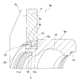
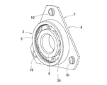
- FIG. 1 is an orthographic view of a combination of an outer ring and a mounting plate constituting a rolling bearing unit with a mounting plate of a first example of an embodiment of the present invention as viewed from the side where the mounting plate is installed.
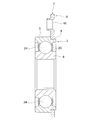
- FIG. 2 is a partial perspective view showing a state cut along a line XX in FIG.
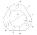
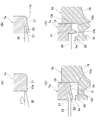
- FIG. 3 is an orthographic view of the mounting plate before being combined with the outer ring in the first example of the embodiment of the present invention, viewed from the same direction as FIG. 4 (A) to 4 (C) show a process of combining the mounting plate and the outer ring in the first example of the embodiment of the present invention, and FIG. 4 (A) shows that the mounting plate is assembled to the outer ring.
- FIG. 4 (A) shows that the mounting plate is assembled to the outer ring.
- FIG. 4B is a cross-sectional view showing a state in which the peripheral edge of the holding hole is pressed with a punch on the side surface in the axial direction of the mounting plate, and FIG. It is sectional drawing which shows the state which is making the latching protrusion engage with the latching ditch
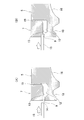
- 5 (A) to 5 (D) show a process of combining the mounting plate and the outer ring in the second example of the embodiment of the present invention.
- FIG. 5 (A) is a side view in the axial direction of the mounting plate.
- FIG. 5B is a cross-sectional view showing a state in which the punch is pressed against the peripheral portion of the holding hole, and FIG.
- FIG. 5B shows a state in which a V-shaped concave groove is formed in the peripheral portion of the holding hole in the mounting plate.
- FIG. 5C is a cross-sectional view showing a state in which the mounting plate is assembled to the outer ring and the peripheral edge of the holding hole is pressed with a punch on the axial side surface of the mounting plate.
- FIG. 5D is a cross-sectional view showing a state in which the locking protrusion is formed on the mounting plate and at the same time the locking protrusion is engaged with the locking groove of the outer ring.
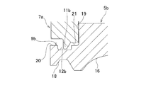
- FIG. 6 is a partial cross-sectional view showing a state in which the locking protrusion of the mounting plate and the locking groove of the outer ring are engaged in the third example of the embodiment of the present invention.
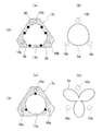
- FIG. 7A and 7A are schematic views of the mounting plate in the fourth example of the embodiment of the present invention when viewed from the same direction as FIG. 3, and FIGS.
- FIG. 7 is a diagram which shows the change of the roundness of an outer ring accompanying insertion of a bolt in a mounting hole of a mounting plate
- Drawing 7 (B) (a) (b) shows an embodiment of the present invention. It is a figure similar to FIG. 7 (A) (a) (b) about the structure which is not employ
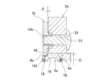
- FIG. 8 is a cross-sectional view of the screw fixing portion of the mounting plate with respect to the housing for explaining the reason why the roundness of the outer ring deteriorates as the bolt is tightened.
- FIG. 8 is a cross-sectional view of the screw fixing portion of the mounting plate with respect to the housing for explaining the reason why the roundness of the outer ring deteriorates as the bolt is tightened.
- FIG. 8 is a cross-sectional view of the screw fixing portion of the mounting plate
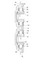
- FIG. 9 is an orthographic view of the mounting plate before being combined with the outer ring in the fifth example of the embodiment of the present invention, viewed from the same direction as FIG.
- FIG. 10 is a sectional view showing an assembled state of the rolling bearing unit with a mounting plate in the fifth example of the embodiment of the present invention.
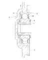
- FIG. 11 is a partial cross-sectional view showing an example of an assembly state of a rolling bearing unit with a mounting plate in a housing in a conventional structure.
- FIG. 12 is a perspective view showing a first example of a conventional structure of a rolling bearing unit with a mounting plate.
- FIG. 13 is a cross-sectional view showing a first example of a conventional structure.
- FIG. 14 is a partial cross-sectional view showing a second example of a conventional structure of a rolling bearing unit with a mounting plate.
- 15 (A) and 15 (B) show the assembly process of the second example of the conventional structure in the order of steps
- FIG. 15 (A) is a partial cross-sectional view showing a state where the mounting plate is assembled to the outer ring.
- FIG. 15 (B) shows that the peripheral edge of the holding hole is pressed with a punch on the axial side surface of the mounting plate to form a locking projection on the mounting plate, and at the same time, the locking projection is engaged with the locking groove in the outer ring.
- FIG. 16 is a partial cross-sectional view for explaining a problem that occurs in the assembly process of the conventional structure.
- the rolling bearing unit 8a with the mounting plate of this example is configured by combining the radial rolling bearing 3a (see FIG. 10) and the mounting plate 7a in a relatively rotatable and non-separable manner.
- the radial rolling bearing 3a includes an outer ring 5a, an inner ring 6 (see FIG. 10), and balls 24 (see FIG. 10) that are a plurality of rolling elements.
- the inner ring 6 is made of a hard metal such as bearing steel as a whole, and a single-row deep groove type inner ring raceway is provided in the axially intermediate portion of the outer peripheral surface.
- the balls 24 which are rolling elements are provided between the outer ring raceway 16 of the outer ring 5a and the inner ring raceway of the inner ring 6 so as to freely roll.
- the present invention is widely applied to a radial rolling bearing unit with a mounting plate regardless of its type.
- a single row deep groove type ball bearing is used as the radial rolling bearing 3a. It is preferable to use it. The reason for this is that the dynamic torque is small, and the respective constituent members are not inadvertently separated even before being assembled to the rotation support portion.
- the following description will focus on the structure of the combined portion of the outer ring 5a and the mounting plate 7a of the radial rolling bearing 3a and the method of assembling the outer ring 5a and the mounting plate 7a, which are the features of this example.
- the radial rolling bearing 3a is provided with the holder
- the outer ring 5a is made of a hard metal such as bearing steel in an annular shape as a whole, a single row deep groove type outer ring raceway 16 is formed at the axially intermediate portion of the inner peripheral surface, and seal rings 17 (see FIG. 14) is formed over the entire circumference. Further, a small-diameter step portion 9a having a smaller diameter than the outer diameter of the outer peripheral surface of the outer ring 5a is provided at one end portion in the axial direction of the outer peripheral surface of the outer ring 5a (the left end portion in FIGS. 2 and 4). 5a is formed concentrically with the outer peripheral surface (the outer peripheral surface of the portion other than the one end portion in the axial direction where the small diameter step portion 9a is formed).
- the axial base of the small diameter step 9a (the right end in FIGS. 2 and 4) and the axial intermediate portion of the outer peripheral surface of the outer ring 5a (the portion adjacent to the small diameter step 9a in the axial direction)
- a step surface 19 extending in the radial direction of the outer ring 5a, that is, in a direction perpendicular to the central axis of the outer ring 5a.
- a locking groove 12a is provided over the entire circumference of the small-diameter step portion 9a, excluding the end portion in the direction, from the intermediate portion in the axial direction to the base portion in the axial direction. Therefore, the bank-like locking protrusion 20 extends over the entire circumference at the axial end (tip) of the small diameter step 9a, that is, between the locking groove 12a and the tip surface of the small diameter step 9a. Is provided.
- the mounting plate 7a has a substantially hexagonal shape formed by cutting a top portion of an equilateral triangle into a partial arc shape by a plastically deformable metal plate such as a mild steel plate. 13a is provided.
- mounting holes 10a are provided at three circumferentially spaced intervals around the holding hole 13a in the mounting plate 7a.
- the thickness T of the mounting plate 7a is substantially the same as the length L of the small-diameter step portion 9a (T ⁇ L), and from the width W of the locking groove 12a. (T> W).
- the inner diameter of the holding hole 13a (the inner diameter of the portion deviated in the circumferential direction from the large-diameter portion 21 formed in a state of being recessed radially outward from the inner peripheral edge of the holding hole 13a)
- R 13 (see FIG. 3) Is slightly larger than the outer diameter d 9 (see FIG. 1 and FIG. 4) of the small-diameter step portion 9a (locking protrusion 20), and the portion of the outer ring 5a adjacent to the small-diameter step portion 9a in the axial direction is It is smaller than the outer diameter D (see FIG. 4) (d 9 ⁇ R 13 ⁇ D).
- the inner diameter R 13 of the retaining hole 13a the difference between the outer diameter d 9 of the small-diameter step section 9a has become negligible. For this reason, the amount of swinging of the mounting plate 7a with respect to the outer ring 5a can be suppressed to a small extent, and the work of fixing the mounting plate 7a to the housing 2 (see FIG. 11) with ease is facilitated. The handling property of 8a can be improved.
- the difference (R 13 ⁇ d 9 ) between the inner diameter R 13 and the outer diameter d 9 is preferably 0.01% to 2%, more preferably 0.01% to 1% of the inner diameter R 13. Is more preferable.
- the notch-shaped large-diameter portions 21 are formed at three positions at equal intervals in the circumferential direction of the holding holes 13a so as to be recessed radially outward from the portions adjacent in the circumferential direction.
- the metal material soft steel which comprises the attachment plate 7a not in the peripheral part of holding hole 13a itself but in a part of peripheral part of each large diameter part 21, specifically, the substantially central position regarding the circumferential direction.
- the locking projection 11a is provided in a state of projecting radially inward from the peripheral edge of the large-diameter portion 21 by plastically deforming.
- the diameter R 11a of the inscribed circle of each of the locking projection 11a is smaller than the outer diameter d 9 of the engaging projecting portions 20 provided in the axial end portion of the cylindrical portion 9a, and a locking
- the diameter d 12a or more of the bottom of the concave groove 12a (d 12a ⁇ R 11a ⁇ d 9 ), preferably larger (d 12a ⁇ R 11a ⁇ d 9 ).
- the outer ring 5a provided with the small-diameter step 9a (the locking protrusion 20 and the locking groove 12a) and the mounting plate 7a provided with the large-diameter portion 21 and the locking protrusion 11a are the locking protrusion 11a.
- the engaging protrusion 11a is engaged with the engaging concave groove 12a so as to be relatively rotatable, and a step closer to the inner diameter of one side surface (right side surface in FIGS. 2 and 4) of the mounting plate 7a
- the surface 19 is engaged. In this state, the displacement of the mounting plate 7a to the left in FIG.
- the thickness T 11a of the locking projection 11a is smaller than the width W of the locking groove 12a (T 11a ⁇ W).
- the outer ring 5a and the mounting plate 7a are concentrically arranged, there is a minute gap between the tip of the locking protrusion 11a (the inner end in the radial direction) and the bottom surface of the locking groove 12a. Accordingly, the outer ring 5a and the mounting plate 7a are in a state of being relatively rotatable and not separated.
- the locking grooves 12a are provided over the entire circumference, but alternatively, locking grooves extending in the circumferential direction are provided at a plurality of locations in the circumferential direction at positions aligned with the large diameter portion 21. It is also possible to provide it.
- the length of the locking groove is preferably equal to or greater than the length of the large diameter portion 21.
- the attachment holes 10a are provided at three positions at equal intervals in the circumferential direction around the holding hole 13a. And the diameter of the inscribed circle of these mounting holes 10a is larger than the outer diameter of the outer ring 5a. Therefore, bolts, studs, etc. inserted through these mounting holes 10a do not interfere with a part of the outer ring 5a.
- the mounting holes 10a need only be provided at a plurality of circumferential locations (two or more locations), preferably at a plurality of circumferentially equidistant locations, and the mounting holes 10a can be provided at four or more circumferential intervals. However, in order to fulfill the function of attaching the rolling bearing unit 8a with attachment plate to the housing 2 (see FIG. 11), it is sufficient to provide the attachment holes 10a at three circumferentially spaced intervals.
- the operation of combining the mounting plate 7a with the outer ring 5a is performed as follows. First, as shown in FIG. 4A, the small diameter step 9a of the outer ring 5a is fitted into the holding hole 13a of the mounting plate 7a. Further, in this state, the support surface of the restraining jig 22 is brought into contact with a portion (diameter intermediate portion) that exists radially outward from the outer ring 5a on one axial side surface of the mounting plate 7a. The step surface 19 of the outer ring 5a and the one side surface in the axial direction of the mounting plate 7a are slightly separated from each other so that the thrust load applied to the mounting plate 7a when the locking projection 11a is processed is not applied to the outer ring 5a.
- the locking protrusion is formed with the end surface on the opposite side of the axially opposite end surfaces of the outer ring being in contact with the support surface of the receiving tool. Is also possible.
- a part of the peripheral edge of the large-diameter portion 21 (the center in the circumferential direction) is a part of the other axial side surface (the left side surface in FIGS. 2 and 4) of the mounting plate 7a.
- the tip surface of the punch 23 provided with protrusions at three circumferentially equal intervals is abutted.
- the inner diameter side edge of the punch 23 is projected inward in the radial direction from the peripheral edge of the large diameter portion 21.
- the punch 23 is pressed toward the step surface 19, and the center position in the circumferential direction of the peripheral portion of the large-diameter portion 21 in the mounting plate 7a is strongly pressed.
- the locking projection 11a is obtained by moving (plastically deforming) the metal material present in the peripheral portion of the large diameter portion 21 radially inward.
- the locking projection 11a and the locking groove 12a are engaged.
- the strength and rigidity of the outer ring 5a are particularly large. Even if not, the outer ring 5a will not be damaged such as deformation. Also, of the holding hole 13a, the portion of the inner diameter R 13 deviated from the large diameter portion 21, since only large slightly or than the outer diameter d 9 of the cylindrical portion 9a, the outer ring 5a and the mounting plate 7a is In the state of being combined with each other, there is almost no shaking in the radial direction.
- the locking projection 11a is formed by plastically deforming the peripheral edge of the large diameter portion 21 radially inward.
- the diameter R21 of the inscribed circle of the large diameter portion 21 is the locking protrusion 20 than the outer diameter d 9 of greater than 2 times the radial height h 21 of the stepped portion between the portion and the large diameter portion 21 which deviates from the large diameter portion 21 of the retaining hole 13a (d 9 + 2h 21 ⁇ R 21 ).
- the diameter R 11a of the inscribed circle of the locking projection 11a is smaller than the outer diameter d 9 of the engaging projecting portions 20, the step shown in FIG. 4 (C) from FIG. 4 (B) It is after the state which the process of the latching protrusion 11a advanced to some extent on the way.
- the relationship between the radial height h 21 of the stepped portion between the portion of the holding hole 13 a that is out of the large diameter portion 21 and the large diameter portion 21 and the axial width W 20 of the locking protrusion 20 is appropriately set. If regulated, as shown in FIG. 4B, the tip of the locking projection 11a and the outer peripheral surface of the locking projection 20 do not hit each other during the processing of the locking projection 11a. Further, as shown in FIG. 4 (C), at a processing completion status of the locking projection 11a, the diameter R 11a of the inscribed circle of the locking projection 11a than the outer diameter d 9 of the engaging projecting portions 20 Can be made sufficiently small.
- the small-diameter step is provided at any stage. A force directed radially inward is not applied to the portion 9a. Therefore, no harmful deformation occurs in the outer ring 5a, the generation of defective products can be suppressed, and the yield of the rolling bearing unit 8a with a mounting plate can be improved.
- the radial height h 21 of the stepped portion is 0.1% to 10%, more preferably 0.5% to 5%, of the inner diameter R 13a of the holding hole 13a.
- the axial width W 20 of the locking protrusion 20 is 10% to 60% of the axial length L of the small diameter step 9a (the thickness T of the mounting plate 7a), more preferably 20%. ⁇ 50%.
- the axial width W 20 of the engagement projecting portions 20 is less than 10% of the axial length L of the cylindrical portion 9a may not be able to sufficiently secure the strength of the engaging projecting portions 20 .
- the axial width W 20 of the engagement projecting portions 20 is greater than 60% of the axial length L of the cylindrical portion 9a, the width of the locking groove 12a is too small, the locking groove There is a possibility that the side surface of 12a interferes with the locking projection 11a.
- FIG. 5 shows a second example of the embodiment of the present invention.
- the operation of forming the locking projection 11b on the peripheral edge of the large diameter portion 21 in the holding hole 13a of the mounting plate 7a is performed in two stages.
- a wedge-shaped first punch having a tip edge sharpened at the peripheral edge portion of the large-diameter portion 21 in the other axial side surface of the mounting plate 7a. 26 is pressed.
- the width dimension regarding the radial direction of the opening part of the axial direction other side surface side of the mounting plate 7a is large in the peripheral part of the large diameter part 21, and this width dimension is toward the back part.
- a V-shaped concave groove 27 is formed which becomes narrower.
- the radially inner portion of the groove 27 is plastically deformed radially inward to form the element locking projection 28 radially inward of the groove 27.
- the first punch 26 is extracted from the concave groove 27, and then, as shown in FIGS. 5C and 5D, the second punch 29 having a flat tip surface is pushed into the concave groove 27. Then, the element locking projection 28, which is a portion located radially inward of the groove 27, is further plastically deformed radially inward. Then, simultaneously with the formation of the locking projection 11b, the locking projection 11b and the locking groove 12a provided on the outer ring 5a side are engaged.
- the load applied to the mounting plate 7a during the processing can be reduced by performing the processing of the locking projection 11b in two stages including the step of using the wedge-shaped first punch 26.
- use of the holding jig 22 can be omitted.
- the deformation of the outer ring can be more reliably prevented by using the holding jig.
- Other parts are the same as in the first example of the embodiment.
- FIG. 6 shows a third example of the embodiment of the present invention.
- the locking groove 12b is entirely formed in the axially intermediate portion (the portion excluding the axial end portion and the axial base portion of the small diameter step portion 9b) of the small diameter step portion 9b provided on the outer ring 5b side. It is provided over the circumference.
- the radial thickness of the axial base portion of the small diameter step portion 9b is ensured, and the strength and rigidity of the portion where the small diameter step portion 9b is formed at one axial end portion of the outer ring 5b can be improved.
- Other parts are the same as in the first example of the embodiment.
- FIGS. 7A and 7A are schematic views for explaining a fourth example of the embodiment of the present invention.
- a notch 30 that is long in the circumferential direction is formed in the inner peripheral edge of the holding hole 13b provided in the central portion of the mounting plate 7b at a portion where the phase in the circumferential direction coincides with the mounting hole 10b.
- the diameter R 30 of the circumscribed circle of these notches 30 is larger than the outer diameter D of the outer peripheral surface of the outer ring 5a (portion adjacent to the cylindrical portion 9a and the axial direction in the outer ring 5a) (see FIG. 8) ( D ⁇ R 30).
- the side surface in the axial direction of the mounting plate 7b and the step surface 19 existing on the outer peripheral surface of the outer ring 5a abut only at the portion between the notches 30 and the portion where the notches 30 are formed. There is no contact. That is, the portion closer to the inner diameter of one side surface in the axial direction of the mounting plate 7b and the step surface 19 are engaged only at a portion where the phase in the circumferential direction is different from that of the mounting hole 10b.
- a plurality of large diameter portions and locking projections are respectively located at portions separated from the notches 30 in the circumferential direction. It is formed. Or if the amount of plastic deformation at the time of forming a latching protrusion is securable, it is also possible to each use the notch 30 as a large diameter part.
- the outer ring 5a is fitted in the holding recess 4a of the housing 2a, and the axial end surface of the outer ring 5a is abutted against the inner end surface of the holding recess 4a. Further, a portion closer to the inner diameter of one side surface (right side surface in FIG. 8) of the mounting plate 7b is abutted against a step surface 19 formed on the outer peripheral surface of the outer ring 5a. In this state, a gap ⁇ exists between one axial side surface of the housing 2a (left side surface in FIG. 8) and one axial side surface of the mounting plate 7b. The gap ⁇ is necessary to support the outer ring 5a with respect to the housing 2a without rattling based on the tightening of the bolt 31.
- the clearance ⁇ is eliminated by tightening the bolt 31 that is inserted through the through hole 32 provided in the housing 2a and screwed into the mounting hole 10b.
- the step surface 19 is pushed by a portion closer to the inner diameter of one side surface in the axial direction of the mounting plate 7b, but the force pushing the step surface 19 is not uniform in the circumferential direction.
- FIGS. 7B and 7A when the mounting plate 7a having a simple circular holding hole 13a is used, the phase in the circumferential direction coincides with the mounting hole 10a.
- the force pushing the step surface 19 at the portion marked with a black circle in FIGS. 7B and 7A, which is close to 10a, is particularly stronger than the other portions.
- the roundness of the outer ring 5a having the stepped surface 19 deteriorates as shown exaggeratedly in FIGS. Deterioration of the roundness of the outer ring 5a may lead to deterioration of acoustic characteristics and durability of the radial rolling bearing 3 (see FIGS. 13 and 14) incorporating the outer ring 5a.
- the portion closer to the inner diameter of the side surface in the axial direction of the mounting plate 7 b has the stepped surface 19 based on the presence of the notch 30. It strongly presses in the part left
- the structure of any one of the first to third examples of the embodiment can be adopted.
- FIG. 9 and 10 show a fifth example of the embodiment of the present invention.
- a plurality of (two in the illustrated example) holding holes 13c are provided in one mounting plate 7c.
- wheel 5a is assembled
- wheel 5a supports the edge part of each separate rotating shaft 1a, 1b with respect to the housing 2b rotatably.
- the mounting plate 7c cannot be rotated with respect to the outer ring 5a, but the deviation between the pitch between the holding holes 13c and the pitch between the holding recesses 4b provided in the housing 2b can be absorbed. That is, the outer ring 5a is fitted into the holding recess 4b without looseness by a light interference fit or the like. Therefore, when the outer ring 5a is assembled inside the holding hole 13c so that relative displacement in the radial direction is impossible, the holding hole It is necessary to strictly match the pitches of 13c.
- the outer ring not only can the outer ring be rotatably held on the inner diameter side of the holding hole, but also some relative displacement in the radial direction. Can also be possible. For this reason, by utilizing the structure of the present invention, it is not necessary to strictly match the pitch of the holding holes 13c, the manufacturing cost can be suppressed, and the assembly work of the outer ring 5a to the holding recess 4b is easy. Can be achieved. In this example as well, any one of the first to third examples of the embodiment can be adopted for the combination of the mounting plate 7c and the outer ring 5a.
- the rolling bearing unit with a mounting plate according to the present invention is suitably applied to an automobile transmission including both a manual transmission and an automatic transmission when the end of the rotary shaft is rotatably supported on the inner surface of the housing.
- the present invention can be widely applied to structures other than automobile transmissions that rotatably support a rotating shaft on a housing.
Landscapes
- Engineering & Computer Science (AREA)
- General Engineering & Computer Science (AREA)
- Mechanical Engineering (AREA)
- Rolling Contact Bearings (AREA)
- Mounting Of Bearings Or Others (AREA)
Description
本発明は、自動車用変速機などを構成する回転軸の端部を、ハウジングの内面に回転自在に支持するために使用される、取付板付き転がり軸受ユニットおよびその製造方法に関する。
図11に示すように、自動車用変速機を構成するカウンターシャフトなどの回転軸1の端部は、自動車用変速機の構成部品を収容するハウジング2の内面に、単列深溝型の玉軸受などのラジアル転がり軸受3により、回転自在に支持される。具体的には、ハウジング2の内面に円形の保持凹部4が設けられ、この保持凹部4に、ラジアル転がり軸受3を構成する外輪5が、締り嵌めで内嵌固定される。回転軸1の端部は、ラジアル転がり軸受3を構成する内輪6に、締り嵌めなど、径方向のがたつきを抑えた嵌合状態で内嵌される。外輪5は、リテーナプレートと呼ばれる取付板7により、保持凹部4の奥部に向けて抑え付けられ、保持凹部4から抜け出すことが防止されている。
ラジアル転がり軸受3と取付板7は、特開2008-267585号公報、特開2009-030794号公報、特開2009-036319号公報などに記載されているように、取付板付き転がり軸受ユニットとして一体化され、ハウジング2への組み付けの容易化が図られている。図12および図13に、取付板付き転がり軸受ユニットの1例を示す。この取付板付き転がり軸受ユニット8は、ラジアル転がり軸受3を構成する外輪5の外周面の軸方向一端部に設けた小径段部9に、取付板7を外輪5に対する回転を可能に外嵌させることにより構成される。取付板付き転がり軸受ユニット8は、外輪5を保持凹部4に締り嵌めで内嵌させ、かつ、取付板7の片面をハウジング2の内面に突き当てることにより、ハウジング2内に組み付けられる。さらに、取付板7を外輪5に対し回転させ、取付板7の外径寄り部分に形成した、ねじ孔もしくは通孔からなる取付孔10と、ハウジング2の内面に開口した通孔もしくはねじ孔(図示省略)とを整合させ、ねじもしくはボルトを用いてねじ止めすることにより、外輪5は、保持凹部4内に、がたつきなく、かつ、保持凹部4からの抜け出しが防止された状態で、支持固定される。
取付板付き転がり軸受ユニット8では、取付板7が、相対回転可能かつ非分離に、外輪5に対して結合されている。回転可能とする理由は、外輪5を保持凹部4に締り嵌めなど、径方向のがたつきを防止した嵌合状態で内嵌させた後に、取付板7の取付孔10と、ハウジング2の通孔またはねじ孔とを整合させるためである。また、非分離とする理由は、ラジアル転がり軸受3と取付板7とを一体として取り扱えるようにして、部品管理、組み立て作業などの容易化を図るためである。
取付板7を相対回転可能かつ非分離に外輪5に対して結合するために、特開2008-267585号公報に記載された構造の場合、図14に示すように、取付板7の内周縁の円周方向複数箇所に形成した係止突部11を、外輪5側の小径段部9の外周面に設けた係止凹溝12に係合させている。具体的には、図15(A)に示すように、取付板7の保持孔13に小径段部9を内嵌させた状態で、図15(B)に示すように、内径が一定である、取付板7の保持孔13の周縁部のうち、円周方向複数箇所を軸方向に押圧し、取付板7の内周縁の一部を径方向内方に塑性変形させることにより、複数の係止突部11を形成し、かつ、これらの係止突部11を係止凹溝12に係合させている。
この構造の取付板付き転がり軸受ユニットでは、係止突部11と係止凹溝12とを安定して係合させることができず、取付板付き転がり軸受ユニットの歩留りの悪化によりコストが嵩む可能性がある。すなわち、この構造では、取付板7と外輪5との相対回転を許容し、しかも、取付板7と外輪5との同心性を確保するため、取付板7側に設ける保持孔13の内径と、外輪5側に設ける小径段部9の外径との差を僅少とする必要がある。すなわち、図16(A)に示すように、保持孔13に小径段部9を内嵌した状態で、保持孔13の内周面と小径段部9の外周面との間に存在する微小隙間14の径方向に関する幅寸法は僅少である。このため、図16(A)に示すように、取付板7の内周縁に係止突部を形成するに際して、取付板7の軸方向側面で保持孔13の周縁部の一部にパンチ15を押し付けると、図16(B)に示すように、取付板7の内周縁において塑性変形した部分が、小径段部9のうち係止凹溝12から外れた軸方向端部に突き当たってしまう。この結果、係止突部11を形成して係止凹溝12と係合させることができないばかりか、外輪5のうちで小径段部9側の軸方向一端部に、直径が縮まる方向の有害な変形を発生させるおそれがある。
保持孔13の内径を小径段部9の外径よりも十分に大きくすれば、係止突部11が形成されるよりも前に、パンチ15の押し付けに伴って形成される、取付板7の内周縁の一部において塑性変形した部分が、小径段部9の軸方向端部に突き当たってしまうことが防止される。しかしながら、このような構造では、外輪5に対する取付板7の振れ回り量(最大偏心量)が大きくなるため、係止突部11を十分に高く、係止凹溝12を十分に深くしないと、係止突部11と係止凹溝12との係合が外れやすくなるという問題がある。また、取付板7と外輪5との同心性が損なわれるので、この取付板7をハウジング2(図11参照)にねじ止め固定する作業が面倒になるなど、取付板付き転がり軸受ユニット8の取り扱い性が低下するという問題もある。
特開2009-036319号公報には、取付板に設けた保持孔の周縁部に複数の係止突部を、この取付板と外輪とを組み合わせる以前に形成しておき、これら取付板と外輪とを、それぞれを弾性変形させつつ組み合わせる製造方法が記載されている。しかしながら、この場合には、取付板と外輪とを組み合わせる際に、この外輪に有害な変形を生じる可能性がある。
特開2009-030794号公報には、取付板と外輪とを、この外輪側に係止した欠円環状の係止環を介して組み合わせる構造が記載されている。しかしながら、この構造では、部品点数の増大に伴って、取付板付き転がり軸受ユニットの製造コストが嵩むことが避けられない。
本発明は、上述のような事情に鑑み、外輪に有害な変形を生じさせることなく、外輪と取付板との同心性が確保され、かつ、取り扱いが容易である、取付板付き転がり軸受ユニットを低コストで提供することを目的としている。
本発明の取付板付き転がり軸受ユニットは、外輪と、内輪と、複数個の転動体と、取付板とを備える。前記外輪は、内周面に外輪軌道を備える。前記内輪は、前記外輪と同心に配置され、外周面に内輪軌道を備える。前記複数個の転動体は、前記外輪軌道と前記内輪軌道との間に転動自在に設けられる。前記取付板は、保持孔および該保持孔の周囲に設けられた複数個の取付孔を有する。
本発明の取付板付き転がり軸受ユニットにおいては、前記外輪の外周面の軸方向一端部に小径段部が全周にわたって設けられており、該小径段部のうちの軸方向端部よりも軸方向中間寄り部分に、周方向に伸長する係止凹溝が設けられている。
また、前記取付板の保持孔は、前記小径段部の外径よりも大きく、前記外輪の外周面のうち前記小径段部と軸方向に隣接する部分の外径よりも小さな内径を有する。該保持孔の周方向複数箇所には、該保持孔の内周縁から径方向外方に凹入した大径部が設けられている。
それぞれの大径部の周縁部の一部に、該周縁部から径方向内方に突出する係止突部が設けられており、該係止突部の内接円の直径は前記小径段部の軸方向端部の外径よりも小さく、かつ、前記係止凹溝の底部の直径以上となっている。
そして、前記係止突部が、前記係止凹溝に周方向の相対移動を可能に係合することにより、前記外輪と前記取付板とが非分離に組み合わされている。
本発明の取付板転がり軸受ユニットにおいては、前記大径部および前記係止突部は、周方向複数箇所に設けられるが、好ましくは、周方向等間隔の3箇所位置以上に設けられる。
前記係止凹溝は、前記小径段部の軸方向端部を除く部分に、少なくとも周方向に伸長するように形成される。該係止凹溝は、前記小径段部の軸方向端部を除く、前記小径段部の軸方向中間部から軸方向基部までにわたって、かつ、全周にわたって設けられていることが好ましい。あるいは、前記係止凹溝が、前記小径段部の軸方向端部および軸方向基部を除く、前記小径段部の軸方向中間部において、全周にわたって設けられていることが好ましい。なお、該係止凹溝が全周にわたって設けられない場合、前記係止突部が形成される前記大径部と周方向の整合する複数箇所に、該係止凹溝が形成される。
本発明の取付板付き転がり軸受ユニットにおいて、前記保持孔の内周縁のうちで、周方向に関する位相が前記複数個の取付孔と一致する部分に、それぞれ周方向に長く、かつ、外接円の直径が前記外輪の外径よりも大きな切り欠きが形成されており、前記取付板の軸方向片側面の内径寄り部分と、前記外輪の外周面と前記小径段部の軸方向基部との間で径方向に伸長する段差面とを、周方向に関する位相が前記複数個の取付孔と異なる位置で係合させていることが好ましい。
本発明は、前記取付板に前記保持孔が1個のみ設けられた構成の取付板付き軸受ユニットに適用可能であり、この場合、前記外輪と前記取付板とが、該外輪の周方向に相対変位可能に組み合わされる。また、本発明は、前記取付板には前記保持孔が複数個設けられた構成の取付板付き軸受ユニットにも適用可能であり、この場合、前記外輪と前記取付板とが、該保持孔の径方向に相対変位可能に組み合わされる。
なお、本発明の取付板付き転がり軸受ユニットにおいて、前記取付板の前記取付孔の内接円の直径は、前記外輪の外径よりも大きいことが好ましい。
本発明の取付板付き転がり軸受ユニットは、前記外輪の小径段部を、前記係止突部が形成される以前の前記取付板の保持孔に内嵌させた状態で、該取付板の軸方向他側面のうちで、前記大径部の周縁部の一部を、前記外輪の外周面と前記小径段部の軸方向基部との間で径方向に伸長する段差面に向けて押圧することにより、前記大径部の周縁部の一部を径方向内方に塑性変形させて前記係止突部を形成し、かつ、該係止突部と前記係止凹溝とを係合させて、前記外輪と前記取付板とを組み合わせる工程を備えた製造方法により、得ることが可能である。
なお、本発明の製造方法においては、前記係止突部を形成するに際して、前記係止突部が形成される以前の前記取付板の軸方向他側面のうちで、前記大径部の周縁部の一部に、楔状の第1パンチを押し付け、該大径部の周縁部に、該取付板の軸方向他側面側の開口するV字状の凹溝を形成し、かつ、該大径部の周縁部の一部のうち、該凹溝よりも径方向内側に位置する部分を径方向内方に塑性変形させ、次に、該凹溝内に第2パンチを押し込み、前記凹溝よりも径方向内側に位置する部分をさらに径方向内方に塑性変形させて、前記係止突部を形成することもできる。
また、前記外輪の周囲に、該外輪を囲むようにして、抑え治具を配置し、前記係止突部を形成するに際して、該抑え治具により前記取付板の軸方向片側面の径方向中間部分を支承させることにより、前記外輪に加工荷重が加わることを防止することが好ましい。
本発明の取付板付き転がり軸受ユニットの構造では、外輪側の係止凹溝と係合する、取付板側の係止突部を、前記取付板の内周縁のうちで複数箇所に設けられた大径部の周縁部の一部を径方向内方に塑性変形させることにより形成するため、この係止突部の加工途中において、取付板のうち塑性変形させられる部分が、外輪の小径段部の軸方向端部に突き当たって、この部分が、小径段部の外周面を径方向内方に強く押圧することがない。よって、前記外輪と前記取付板との組み合わせ時に、いずれの部品にも有害な力が作用することがなくなり、これらの部品に有害な変形が生じることが防止され、取付板付き転がり軸受ユニットの歩留りの向上が図られる。
また、本発明の構造では、前記取付板の内周面と前記小径段部の外周面とは、前記大径部以外の部分は、微小隙間を介して対向する。したがって、前記外輪に対する前記取付板の振れ回り量(最大偏心量)を僅少に抑えることができるため、外輪と取付板との同心性を確保することができる。
さらに、本発明の構造では、外輪と取付板とを、別部品を使用することなく、直接組み合わせることが可能な構造であるため、部品製造コスト、部品管理コスト、組立コストをいずれも抑えることができ、取付板付き転がり軸受ユニットの低コスト化を図ることができる。
[実施の形態の第1例]
図1~図4は、本発明の実施の形態の第1例を示している。本例の取付板付き転がり軸受ユニット8aは、ラジアル転がり軸受3a(図10参照)と取付板7aとを、相対回転可能かつ非分離に組み合わせることにより構成されている。ラジアル転がり軸受3aは、従来構造と同様に、外輪5aと内輪6(図10参照)と複数個の転動体である玉24(図10参照)とを備える。このうち、内輪6は、軸受鋼などの硬質金属により全体を円環状に作製されており、外周面の軸方向中間部に単列深溝型の内輪軌道が設けられており、外輪5aの内径側に、外輪5aと同心に配置される。また、転動体である玉24は、外輪5aの外輪軌道16と内輪6の内輪軌道との間に転動自在に設けられる。なお、本発明は、取付板付きのラジアル転がり軸受ユニットに、その種類を問わずに、広く適用されるが、特に、本発明においては、ラジアル転がり軸受3aとして、単列深溝型の玉軸受を使用することが好ましい。この理由は、動トルクが小さいことと、回転支持部に組み付ける以前の状態でも、それぞれの構成部材が不用意に分離することがないためとである。なお、以下の説明は、本例の特徴部分である、ラジアル転がり軸受3aの外輪5aと取付板7aの組み合わせ部分の構造、および、外輪5aと取付板7aの組立方法を中心に行う。なお、ラジアル転がり軸受3aは、保持器25(図10参照)を備えることが好ましい。
図1~図4は、本発明の実施の形態の第1例を示している。本例の取付板付き転がり軸受ユニット8aは、ラジアル転がり軸受3a(図10参照)と取付板7aとを、相対回転可能かつ非分離に組み合わせることにより構成されている。ラジアル転がり軸受3aは、従来構造と同様に、外輪5aと内輪6(図10参照)と複数個の転動体である玉24(図10参照)とを備える。このうち、内輪6は、軸受鋼などの硬質金属により全体を円環状に作製されており、外周面の軸方向中間部に単列深溝型の内輪軌道が設けられており、外輪5aの内径側に、外輪5aと同心に配置される。また、転動体である玉24は、外輪5aの外輪軌道16と内輪6の内輪軌道との間に転動自在に設けられる。なお、本発明は、取付板付きのラジアル転がり軸受ユニットに、その種類を問わずに、広く適用されるが、特に、本発明においては、ラジアル転がり軸受3aとして、単列深溝型の玉軸受を使用することが好ましい。この理由は、動トルクが小さいことと、回転支持部に組み付ける以前の状態でも、それぞれの構成部材が不用意に分離することがないためとである。なお、以下の説明は、本例の特徴部分である、ラジアル転がり軸受3aの外輪5aと取付板7aの組み合わせ部分の構造、および、外輪5aと取付板7aの組立方法を中心に行う。なお、ラジアル転がり軸受3aは、保持器25(図10参照)を備えることが好ましい。
外輪5aは、軸受鋼などの硬質金属により全体を円環状に作製されており、内周面の軸方向中間部に単列深溝型の外輪軌道16が、軸方向両端部にシールリング17(図14参照)の外周縁を係止するための係止溝18が、それぞれ全周にわたって形成されている。また、外輪5aの外周面の軸方向一端部(図2および図4の左端部)には、外輪5aの外周面の外径よりも小径である、小径段部9aが、全周にわたって、外輪5aの外周面(小径段部9aが形成された軸方向一端部以外の部分の外周面)と同心に形成されている。小径段部9aの軸方向基部(図2および図4の右端部)と外輪5aの外周面の軸方向中間部(小径段部9aと軸方向に隣接する部分)との間には、外輪5aの径方向、すなわち外輪5aの中心軸に対し直角方向に伸長する段差面19が存在する。また、小径段部9aの外周面のうちの軸方向端部(図2および図4の左端部)よりも軸方向中間寄り部分、より具体的には、本例では、小径段部9aの軸方向端部を除く、小径段部9aの軸方向中間部から軸方向基部までの全体において、係止凹溝12aが全周にわたって設けられている。したがって、小径段部9aの軸方向端部(先端部)、すなわち、係止凹溝12aと小径段部9aの先端面との間部分に、土手状の係止突条部20が全周にわたって設けられている。
取付板7aは、軟鋼板などの塑性変形可能な金属板により、正三角形の頂部を部分円弧形に切除したような、略六角形状となっており、その中心部には1個の保持孔13aが設けられている。また、取付板7aのうち保持孔13aの周囲には、周方向等間隔3箇所に取付孔10aが設けられている。なお、図2に示すように、本例では、取付板7aの厚さTは、小径段部9aの長さLとほぼ同じ(T≒L)であり、係止凹溝12aの幅Wよりも大きくなっている(T>W)。
本例では、保持孔13aの内径(保持孔13aの内周縁から径方向外方凹入した状態で形成された大径部21から周方向に外れた部分の内径)R13(図3参照)は、小径段部9a(係止突条部20)の外径d9(図1および図4参照)よりもわずかに大きく、外輪5aのうちで小径段部9aと軸方向に隣接する部分の外径D(図4参照)よりも小さくなっている(d9<R13<D)。このように、本例では、保持孔13aの内径R13と、小径段部9aの外径d9との差が僅少となっている。このため、外輪5aに対する取付板7aの振れ回り量を僅少に抑えることができ、取付板7aをハウジング2(図11参照)にねじ止め固定する作業が容易になるなど、取付板付き転がり軸受ユニット8aの取り扱い性の向上を図ることができる。なお、この内径R13と外径d9との差(R13-d9)は、内径R13の0.01%~2%であることが好ましく、0.01%~1%であることがさらに好ましい。内径R13と外径d9との差(R13-d9)が内径R13の0.01%よりも小さい場合には、取付板7aに対して外輪5aが回転しにくくなって、取付板付き転がり軸受ユニット8aの組み付け性が低下する。一方、内径R13と外径d9との差(R13-d9)が内径R13の2%よりも大きい場合には、取付板7aが外輪5aに対して相対回転しやすく、取付孔10aとハウジング2のねじ孔もしくは通孔とを整合させにくくなるため、取付板付き転がり軸受ユニット8aの組み付け性が低下する。
本例では、保持孔13aの周方向等間隔の3箇所に、切り欠き状の大径部21が、周方向に隣接する部分よりも径方向外方に凹入する状態で形成されている。そして、保持孔13a自体の周縁部ではなく、それぞれの大径部21の周縁部の一部、具体的には、その周方向に関してほぼ中央位置に、取付板7aを構成する金属材料(軟鋼)を塑性変形させることにより、大径部21の周縁部から径方向内方に突出する状態で、係止突部11aが設けられている。それぞれの係止突部11aの内接円の直径R11aは、小径段部9aの軸方向端部に設けられている係止突条部20の外径d9よりも小さく、かつ、係止凹溝12aの底部の直径d12a以上(d12a≦R11a<d9)、好ましくはより大きくなっている(d12a<R11a<d9)。
小径段部9a(係止突条部20および係止凹溝12a)を設けた外輪5aと、大径部21および係止突部11aを備えた取付板7aとは、係止突部11aと係止凹溝12aとを係合させることにより、相対回転可能かつ非分離に組み合わされる。すなわち、係止突部11aを係止凹溝12aに、相対回転可能に係合させ、かつ、取付板7aの軸方向片側面(図2および図4の右側面)の内径寄り部分と、段差面19とを係合させる。この状態で、取付板7aが外輪5aに対し、図2の左方に変位することは、係止突部11aと係止突条部20との係合により阻止される。これに対して、図2の右方に変位することは、取付板7aの軸方向片側面の内径寄り部分と段差面19との係合により阻止される。また、この取付板7aにより、外輪5aを抑え付けることが可能となる。これら取付板7aおよび外輪5aの軸方向に関して、係止突部11aの厚さT11aは、係止凹溝12aの幅Wよりも小さい(T11a<W)。また、外輪5aと取付板7aとを同心に配置した状態で、係止突部11aの先端(径方向内端)と係止凹溝12aの底面との間には微小隙間が存在する。したがって、外輪5aと取付板7aとは、相対回転可能かつ非分離に組み合わされた状態となる。なお、本例では、係止凹溝12aを全周にわたって設けているが、代替的に、大径部21と整合する位置に、周方向に伸長する係止凹溝を周方向の複数箇所に設けることも可能である。この場合、係止凹溝の長さは大径部21の長さ以上とすることが好ましい。
本例において、取付孔10aは、保持孔13aの周囲で円周方向等間隔3箇所位置に設けられている。そして、これらの取付孔10aの内接円の直径は、外輪5aの外径よりも大きい。したがって、これらの取付孔10aに挿通したボルトやスタッドなどが、外輪5aの一部と干渉することはない。なお、取付孔10aは、周方向複数箇所(2箇所以上)、好ましくは周方向等間隔複数箇所に設けられていればよく、周方向等間隔4箇所以上に取付孔10aを設けることも可能であるが、取付板付き転がり軸受ユニット8aをハウジング2(図11参照)に取り付けるという機能を果たすためには、周方向等間隔3箇所に取付孔10aを設ければ十分である。
外輪5aに対して取付板7aを組み合わせる作業は、次のようにして行う。 まず、図4(A)に示すように、外輪5aの小径段部9aを取付板7aの保持孔13aに内嵌する。また、この状態で、取付板7aの軸方向片側面のうちで外輪5aよりも径方向外方に存在する部分(径方向中間部分)に、抑え治具22の支承面を当接させる。外輪5aの段差面19と取付板7aの軸方向片側面とを、わずかに離隔させて、係止突部11aの加工時に取付板7aに加わるスラスト荷重が、外輪5aに加わらないようにする。ただし、外輪の軸方向に関する強度および剛性が十分に高い場合には、必ずしも抑え治具を使用する必要はない。すなわち、この場合には、外輪の軸方向両端面のうちで小径段部を設置したのと反対側の端面を受具の支承面に当接させた状態で、係止突部を形成することも可能である。
次に、図4(B)に示すように、取付板7aの軸方向他側面(図2および図4の左側面)の一部で、大径部21の周縁部の一部(周方向中央位置)に対して、周方向等間隔3箇所に突部が設けられたパンチ23の先端面を突き当てる。この際、取付板7aの径方向に関して、パンチ23の内径側端縁を、大径部21の周縁部よりも径方向内方に突出させた状態とする。この状態からパンチ23を段差面19に向けて押圧し、取付板7aのうちで大径部21の周縁部の周方向中央位置を強く押圧する。そして、図4(B)および図4(C)に示すように、大径部21の周縁部に存在する金属材料を径方向内方に移動(塑性変形)させることにより、係止突部11aを形成すると同時に、係止突部11aと係止凹溝12aとを係合させる。
係止突部11aの加工時に取付板7aに加えられる加工荷重の全部もしくは大部分は、抑え治具22が支承し、外輪5aに加わることはないので、この外輪5aの強度および剛性が特に大きくなくても、この外輪5aに変形などの損傷を生じることはない。また、保持孔13aのうち、大径部21から外れた部分の内径R13は、小径段部9aの外径d9よりもわずかかに大きいだけであるので、外輪5aと取付板7aとは、互いに組み合わされた状態で、径方向に関してがたつくことはほとんどない。なお、係止突部11aの加工は、外輪5aと取付板7aとのみを組み合わせた状態で行うので、取り扱いが容易であるとともに、ラジアル転がり軸受3の他の構成部品を傷める可能性がない。また、本例では、外輪5aと取付板7aとを直接組み合わせているため、部品製造コスト、部品管理コスト、組立コストをいずれも抑えることができ、取付板付き転がり軸受ユニット8aの低コスト化を図ることができる。
係止突部11aは、大径部21の周縁部を径方向内方に塑性変形させることにより形成されるが、大径部21の内接円の直径R21は、係止突条部20の外径d9よりも、保持孔13aのうち大径部21から外れた部分と大径部21との段差部の径方向高さh21の2倍分以上大きい(d9+2h21<R21)。本例では、係止突部11aの内接円の直径R11aが係止突条部20の外径d9よりも小さくなるのは、図4(B)から図4(C)に示す工程の途中で、係止突部11aの加工がある程度進んだ状態以降である。したがって、保持孔13aのうち大径部21から外れた部分と大径部21との段差部の径方向高さh21と係止突条部20の軸方向幅W20との関係を適切に規制すれば、図4(B)に示すように、係止突部11aの加工途中の段階で、係止突部11aの先端と係止突条部20の外周面とが突き当たることはない。また、図4(C)に示すように、係止突部11aの加工完了の状態で、係止突部11aの内接円の直径R11aを係止突条部20の外径d9よりも十分に小さくすることができる。
したがって、取付板7aの内周縁部の係止突部11aと、外輪5aの小径段部9aの外周面に形成した係止凹溝12aとを係合させる際に、いずれの段階でも、小径段部9aに径方向内方に向いた力が加わることはない。このため、外輪5aに有害な変形を生じることはなく、不良品の発生を抑制できて、取付板付き転がり軸受ユニット8aの歩留りの向上を図ることができる。なお、段差部の径方向高さh21は、保持孔13aの内径R13aの0.1%~10%であり、さらに好ましくは、0.5%~5%である。径方向高さh21が内径13aの0.1%よりも小さい場合、係止突部11aの加工の際に、この係止突部11aの先端部と係止突条部20の外周面とが干渉する可能性がある。これに対し、径方向高さh21が内径13aの10%よりも大きい場合、係止突部11aと係止突条部20との係合状態が不十分となり、外輪5aが取付板7aから脱落する可能性がある。また、係止突条部20の軸方向幅W20は、小径段部9aの軸方向長さL(取付板7aの厚さT)の10%~60%であり、さらに好ましくは、20%~50%である。係止突条部20の軸方向幅W20が小径段部9aの軸方向長さLの10%よりも小さい場合には、係止突条部20の強度を十分確保できなくなる可能性がある。一方、係止突条部20の軸方向幅W20が小径段部9aの軸方向長さLの60%よりも大きい場合、係止凹溝12aの幅が小さくなりすぎて、係止凹溝12aの側面と係止突部11aとが干渉する可能性がある。なお、本例のその他の部分については、従来の構造と同様である。
[実施の形態の第2例]
図5は、本発明の実施の形態の第2例を示している。本例の場合には、取付板7aの保持孔13aのうちで、大径部21の周縁部に係止突部11bを形成する作業を、2段階に分けて行っている。
図5は、本発明の実施の形態の第2例を示している。本例の場合には、取付板7aの保持孔13aのうちで、大径部21の周縁部に係止突部11bを形成する作業を、2段階に分けて行っている。
すなわち、本例の場合、まず、図5(A)に示すように、取付板7aの軸方向他側面のうちで大径部21の周縁部に、先端縁を尖らせた楔状の第1パンチ26を押し付ける。そして、図5(B)に示すように、大径部21の周縁部に、取付板7aの軸方向他側面側の開口部の径方向に関する幅寸法が広く、奥部に向かう程この幅寸法が狭くなるV字状の凹溝27を形成する。これと同時に、凹溝27よりも径方向内側部分を径方向内方に塑性変形させて、凹溝27よりも径方向内側に素係止突部28を形成する。
その後、第1パンチ26を凹溝27から抜き出してから、図5(C)および図5(D)に示すように、凹溝27内に、平坦な先端面を有する第2パンチ29を押し込んで、凹溝27よりも径方向内側に位置する部分である素係止突部28を、さらに径方向内方に塑性変形させる。そして、係止突部11bを形成すると同時に、係止突部11bと、外輪5a側に設けた係止凹溝12aとを係合させる。
本例の場合、係止突部11bの加工を、楔状の第1パンチ26を使用する工程を含めて、2段階に分けて行うことにより、この加工時に取付板7aに加わる荷重を低減できる。このため、抑え治具22(図4参照)の使用を省略することもできる。ただし、この場合でも、抑え治具を使用することにより、外輪の変形をより確実に防止することが可能となる。その他の部分については、実施の形態の第1例と同様である。
[実施の形態の第3例]
図6は、本発明の実施の形態の第3例を示している。本例の場合、外輪5b側に設けた小径段部9bのうちの軸方向中間部(小径段部9bの軸方向端部と軸方向基部を除いた部分)に、係止凹溝12bが全周にわたって設けられている。このような構成により、小径段部9bの軸方向基部の径方向に関する肉厚が確保され、外輪5bの軸方向一端部で小径段部9bを形成した部分の強度および剛性の向上が図られる。その他の部分については、実施の形態の第1例と同様である。
図6は、本発明の実施の形態の第3例を示している。本例の場合、外輪5b側に設けた小径段部9bのうちの軸方向中間部(小径段部9bの軸方向端部と軸方向基部を除いた部分)に、係止凹溝12bが全周にわたって設けられている。このような構成により、小径段部9bの軸方向基部の径方向に関する肉厚が確保され、外輪5bの軸方向一端部で小径段部9bを形成した部分の強度および剛性の向上が図られる。その他の部分については、実施の形態の第1例と同様である。
[実施の形態の第4例]
図7(A)(a)は、本発明の実施の形態の第4例を説明するための模式図である。本例の場合、取付板7bの中央部に設けた保持孔13bの内周縁のうちで、周方向に関する位相が取付孔10bと一致する部分に、それぞれ周方向に長い切り欠き30が形成されている。これらの切り欠き30の外接円の直径R30は、外輪5aの外周面(外輪5aのうちで小径段部9aと軸方向に隣接する部分)の外径D(図8参照)よりも大きい(D<R30)。したがって、取付板7bの軸方向側面と、外輪5aの外周面に存在する段差面19(図8参照)とは、切り欠き30同士の間部分でのみ当接し、切り欠き30が形成された部分で当接することはない。すなわち、取付板7bの軸方向片側面の内径寄り部分と、段差面19とは、円周方向に関する位相が取付孔10bと異なる部分でのみ係合する。なお、本例の構造を実施する場合、保持孔13bの内周縁に設ける複数の大径部および係止突部(いずれも図示省略)は、それぞれ円周方向に関して切り欠き30から外れた部分に形成される。あるいは、係止突部を形成する際の塑性変形量を確保できれば、切り欠き30をそれぞれ大径部として利用することも可能である。
図7(A)(a)は、本発明の実施の形態の第4例を説明するための模式図である。本例の場合、取付板7bの中央部に設けた保持孔13bの内周縁のうちで、周方向に関する位相が取付孔10bと一致する部分に、それぞれ周方向に長い切り欠き30が形成されている。これらの切り欠き30の外接円の直径R30は、外輪5aの外周面(外輪5aのうちで小径段部9aと軸方向に隣接する部分)の外径D(図8参照)よりも大きい(D<R30)。したがって、取付板7bの軸方向側面と、外輪5aの外周面に存在する段差面19(図8参照)とは、切り欠き30同士の間部分でのみ当接し、切り欠き30が形成された部分で当接することはない。すなわち、取付板7bの軸方向片側面の内径寄り部分と、段差面19とは、円周方向に関する位相が取付孔10bと異なる部分でのみ係合する。なお、本例の構造を実施する場合、保持孔13bの内周縁に設ける複数の大径部および係止突部(いずれも図示省略)は、それぞれ円周方向に関して切り欠き30から外れた部分に形成される。あるいは、係止突部を形成する際の塑性変形量を確保できれば、切り欠き30をそれぞれ大径部として利用することも可能である。
本例の場合、取付板7bに、切り欠き30を設けることにより、取付板7bの円周方向複数箇所(図示の例では3箇所)をハウジング2aに対し、複数本のボルト31により(図8参照)結合固定することに起因する、外輪5aの真円度の悪化を抑えることができる。
すなわち、外輪5aをハウジング2aに組み付けるには、外輪5aをハウジング2aの保持凹部4aに内嵌し、外輪5aの軸方向端面を保持凹部4aの奥端面に突き当てる。また、取付板7bの軸方向片側面(図8の右側面)の内径寄り部分を、外輪5aの外周面に形成した段差面19に突き当てる。この状態で、ハウジング2aの軸方向片面(図8の左側面)と取付板7bの軸方向片側面との間に、隙間δが存在する状態となる。この隙間δは、ボルト31の締め付けに基づいて外輪5aを、ハウジング2aに対し、がたつきなく支持するために必要である。
隙間δは、ハウジング2aに設けた通孔32を挿通し、取付孔10bに螺合した、ボルト31を締め付けることにより解消される。この際、段差面19が取付板7bの軸方向片側面の内径寄り部分により押されるが、この段差面19を押す力は、円周方向に関して均一にはならない。たとえば、図7(B)(a)に示すように、単なる円形の保持孔13aを形成した取付板7aを使用する場合には、周方向に関する位相が取付孔10aと一致し、これらの取付孔10aに近い、図7(B)(a)に黒丸を付した部分で、段差面19を押す力が、他の部分に比べて特に強くなる。この結果、段差面19を有する外輪5aの真円度が、図7の(B)(b)に誇張して示すように悪化する。外輪5aの真円度の悪化は、外輪5aを組み込んだラジアル転がり軸受3(図13および図14参照)の音響特性や耐久性の悪化に結び付く可能性がある。
これに対して、図7(A)(a)に示した本例の構造によれば、切り欠き30の存在に基づき、取付板7bの軸方向側面の内径寄り部分が、段差面19を、図7(A)(a)に黒丸で付した、取付孔10bから円周方向に離れた部分で強く押圧する。また、強く押圧する箇所が、取付孔10bの2倍(6箇所)になる。この結果、段差面19が押圧される力の分布が均一に近くなり、ボルト31の締め付けに伴う外輪5aの真円度の悪化が緩和される。この結果、図7(A)(b)に示すように、ボルト31を締め付けて外輪5aをハウジング2aに固定した状態でも、外輪5aの真円度の悪化を抑えることができて、外輪5aを組み込んだラジアル転がり軸受3の音響特性や耐久性の悪化を防止できる。なお、取付板7bと外輪5aとの組み合わせに関しては、実施の形態の第1例~第3例のいずれかの構造を採用することができる。
[実施の形態の第5例]
図9および図10は、本発明の実施の形態の第5例を示している。本例の場合、1枚の取付板7cに複数の(図示の例では2箇所の)保持孔13cが設けられている。そして、それぞれの保持孔13cの内側に、外輪5aが、保持孔13cの径方向に関する若干の相対変位を可能に組み付けられている。それぞれの外輪5aを備えるラジアル転がり軸受3aは、それぞれ別の回転軸1a、1bの端部をハウジング2bに対し、回転自在に支持する。
図9および図10は、本発明の実施の形態の第5例を示している。本例の場合、1枚の取付板7cに複数の(図示の例では2箇所の)保持孔13cが設けられている。そして、それぞれの保持孔13cの内側に、外輪5aが、保持孔13cの径方向に関する若干の相対変位を可能に組み付けられている。それぞれの外輪5aを備えるラジアル転がり軸受3aは、それぞれ別の回転軸1a、1bの端部をハウジング2bに対し、回転自在に支持する。
本例の構造の場合、外輪5aに対して取付板7cを回転させることはできないが、保持孔13c同士のピッチと、ハウジング2bに設けた保持凹部4b同士のピッチとのずれを吸収できる。すなわち、外輪5aは、保持凹部4bに、軽い締まり嵌めなどにより、がたつきなく内嵌されるため、保持孔13cの内側に外輪5aを、径方向に関する相対変位を不能に組み付けると、保持孔13c同士のピッチを厳密に一致させる必要がある。これに対して、本発明の構造(実施の形態の第1例~第3例参照)によれば、保持孔の内径側に外輪を回転可能に保持できるだけでなく、径方向に関する多少の相対変位も可能にすることができる。このため、本発明の構造を利用することで、保持孔13c同士のピッチを厳密に一致させる必要がなくなり、製造コストを抑えることができ、かつ、保持凹部4bへの外輪5aの組み付け作業の容易化を図ることができる。なお、本例においても、取付板7cと外輪5aとの組み合わせに関しては、実施の形態の第1例~第3例のいずれかを採用することができる。
本発明の取付板付き転がり軸受ユニットは、手動変速機および自動変速機の両方を含む自動車用変速機において、回転軸の端部をハウジングの内面に回転自在に支持する場合に好適に適用されるが、自動車用変速機以外の、回転軸をハウジングに回転自在に支持する構造にも、広く適用することが可能である。
1、1a、1b 回転軸
2、2a ハウジング
3、3a ラジアル転がり軸受
4、4a、4b 保持凹部
5、5a、5b 外輪
6 内輪
7、7a、7b、7c 取付板
8、8a 取付板付き転がり軸受ユニット
9、9a、9b 小径段部
10、10a、10b 取付孔
11、11a、11b 係止突部
12、12a、12b 係止凹溝
13、13a、13b、13c 保持孔
14 微小隙間
15 パンチ
16 外輪軌道
17 シールリング
18 係止溝
19 段差面
20 係止突条部
21 大径部
22 抑え治具
23 パンチ
24 玉
25 保持器
26 第一パンチ
27 凹溝
28 素係止突部
29 第二パンチ
30 切り欠き
31 ボルト
32 通孔
2、2a ハウジング
3、3a ラジアル転がり軸受
4、4a、4b 保持凹部
5、5a、5b 外輪
6 内輪
7、7a、7b、7c 取付板
8、8a 取付板付き転がり軸受ユニット
9、9a、9b 小径段部
10、10a、10b 取付孔
11、11a、11b 係止突部
12、12a、12b 係止凹溝
13、13a、13b、13c 保持孔
14 微小隙間
15 パンチ
16 外輪軌道
17 シールリング
18 係止溝
19 段差面
20 係止突条部
21 大径部
22 抑え治具
23 パンチ
24 玉
25 保持器
26 第一パンチ
27 凹溝
28 素係止突部
29 第二パンチ
30 切り欠き
31 ボルト
32 通孔
Claims (11)
- 内周面に外輪軌道を備える外輪と、
該外輪と同心に配置され、外周面に内輪軌道を備える内輪と、
前記外輪軌道と前記内輪軌道との間に転動自在に設けられている複数個の転動体と、
保持孔および該保持孔の周囲に設けられた複数個の取付孔を有する取付板と、
を備え、
前記外輪の外周面の軸方向一端部に小径段部が全周にわたって設けられており、該小径段部のうちの軸方向端部よりも軸方向中間寄り部分に、周方向に伸長する係止凹溝が設けられており、
前記取付板の保持孔は、前記小径段部の外径よりも大きく、前記外輪の外周面のうち前記小径段部と軸方向に隣接する部分の外径よりも小さな内径を有し、該保持孔の周方向複数箇所には、該保持孔の内周縁から径方向外方に凹入した大径部が設けられており、
それぞれの大径部の周縁部の一部に、該周縁部から径方向内方に突出する係止突部が設けられており、該係止突部の内接円の直径は前記小径段部の軸方向端部の外径よりも小さく、かつ、前記係止凹溝の底部の直径以上となっており、
前記係止突部が、前記係止凹溝に周方向の相対移動を可能に係合することにより、前記外輪と前記取付板とが非分離に組み合わされている、
取付板付き転がり軸受ユニット。 - 前記大径部および前記係止突部が、周方向等間隔の3箇所位置以上に設けられている、請求項1に記載の取付板付き転がり軸受ユニット。
- 前記係止凹溝が、前記小径段部の軸方向端部を除く、前記小径段部の軸方向中間部から軸方向基部までにわたって、かつ、全周にわたって設けられている、請求項1に記載の取付板付き転がり軸受ユニット。
- 前記係止凹溝が、前記小径段部の軸方向端部および軸方向基部を除く、前記小径段部の軸方向中間部において、全周にわたって設けられている、請求項1に記載の取付板付き転がり軸受ユニット。
- 前記保持孔の内周縁のうちで、周方向に関する位相が前記複数個の取付孔と一致する部分に、それぞれ周方向に長く、かつ、外接円の直径が前記外輪の外径よりも大きな切り欠きが形成されており、前記取付板の軸方向片側面の内径寄り部分と、前記外輪の外周面と前記小径段部の基部との間で径方向に伸長する段差面とを、周方向に関する位相が前記複数個の取付孔と異なる位置で係合させている、請求項1に記載の取付板付き転がり軸受ユニット。
- 前記取付板には、前記保持孔が1個のみ設けられており、前記外輪と前記取付板とが、該外輪の周方向に相対変位可能に組み合わされている、請求項1に記載の取付板付き転がり軸受ユニット。
- 前記取付板には、前記保持孔が複数個設けられており、前記外輪と前記取付板とが、該保持孔の径方向に相対変位可能に組み合わされている、請求項1に記載の取付板付き転がり軸受ユニット。
- 前記取付板の前記取付孔の内接円の直径は、前記外輪の外径よりも大きい、請求項1に記載の取付板付き転がり軸受ユニット。
- 請求項1に記載の取付板付き転がり軸受ユニットの製造方法であって、前記外輪の小径段部を、前記係止突部が形成される以前の前記取付板の保持孔に内嵌させた状態で、該取付板の軸方向他側面のうちで、前記大径部の周縁部の一部を、前記外輪の外周面と前記小径段部の基部との間で径方向に伸長する段差面に向けて押圧することにより、前記大径部の周縁部の一部を径方向内方に塑性変形させて前記係止突部を形成し、かつ、該係止突部と前記係止凹溝とを係合させて、前記外輪と前記取付板とを組み合わせる工程を備える、取付板付き転がり軸受ユニットの製造方法。
- 前記係止突部を形成するに際して、前記係止突部が形成される以前の前記取付板の軸方向他側面のうちで、前記大径部の周縁部の一部に、楔状の第1パンチを押し付け、該大径部の周縁部に、該取付板の軸方向他側面側の開口するV字状の凹溝を形成し、かつ、該大径部の周縁部の一部のうち、該凹溝よりも径方向内側に位置する部分を径方向内方に塑性変形させ、次に、該凹溝内に第2パンチを押し込み、前記凹溝よりも径方向内側に位置する部分をさらに径方向内方に塑性変形させて、前記係止突部を形成する、請求項9に記載の取付板付き転がり軸受ユニットの製造方法。
- 前記外輪の周囲に、該外輪を囲むようにして、抑え治具を配置し、前記係止突部を形成するに際して、該抑え治具により前記取付板の軸方向片側面の径方向中間部分を支承させることにより、前記外輪に加工荷重が加わることを防止する、請求項9に記載の取付板付き転がり軸受ユニットの製造方法。
Priority Applications (3)
| Application Number | Priority Date | Filing Date | Title |
|---|---|---|---|
| EP13810076.3A EP2853762B1 (en) | 2012-06-29 | 2013-06-27 | Rolling bearing unit with mounting plate, and method for manufacturing same |
| CN201710052347.4A CN106555816B (zh) | 2012-06-29 | 2013-06-27 | 带有安装板的滚动轴承单元和其制造方法 |
| CN201380034622.XA CN104395628B (zh) | 2012-06-29 | 2013-06-27 | 带有安装板的滚动轴承单元和其制造方法 |
Applications Claiming Priority (4)
| Application Number | Priority Date | Filing Date | Title |
|---|---|---|---|
| JP2012-146398 | 2012-06-29 | ||
| JP2012146398 | 2012-06-29 | ||
| JP2012-181681 | 2012-08-20 | ||
| JP2012181681A JP6003392B2 (ja) | 2012-06-29 | 2012-08-20 | 取付板付転がり軸受ユニットとその製造方法 |
Publications (1)
| Publication Number | Publication Date |
|---|---|
| WO2014003149A1 true WO2014003149A1 (ja) | 2014-01-03 |
Family
ID=49783284
Family Applications (1)
| Application Number | Title | Priority Date | Filing Date |
|---|---|---|---|
| PCT/JP2013/067737 Ceased WO2014003149A1 (ja) | 2012-06-29 | 2013-06-27 | 取付板付き転がり軸受ユニットおよびその製造方法 |
Country Status (4)
| Country | Link |
|---|---|
| EP (1) | EP2853762B1 (ja) |
| JP (1) | JP6003392B2 (ja) |
| CN (2) | CN104395628B (ja) |
| WO (1) | WO2014003149A1 (ja) |
Cited By (5)
| Publication number | Priority date | Publication date | Assignee | Title |
|---|---|---|---|---|
| JP2015152048A (ja) * | 2014-02-12 | 2015-08-24 | 日本精工株式会社 | 軸受装置及び軸受装置の製造方法 |
| JP2016053414A (ja) * | 2014-05-27 | 2016-04-14 | 日本精工株式会社 | 軸受装置及び軸受装置用固定プレート |
| CN106662156A (zh) * | 2014-06-13 | 2017-05-10 | 日本精工株式会社 | 轴承装置和轴承装置的制造方法 |
| CN106795918A (zh) * | 2014-08-27 | 2017-05-31 | 日本精工株式会社 | 轴承装置和轴承装置的制造方法 |
| CN109424653A (zh) * | 2017-09-05 | 2019-03-05 | 舍弗勒技术股份两合公司 | 轴承单元 |
Families Citing this family (6)
| Publication number | Priority date | Publication date | Assignee | Title |
|---|---|---|---|---|
| JP6597002B2 (ja) | 2015-07-14 | 2019-10-30 | 日本精工株式会社 | 軸受装置及び軸受装置の製造方法 |
| CN109072981B (zh) * | 2016-03-30 | 2021-05-11 | Ntn株式会社 | 滚动轴承装置以及板一体型滚动轴承 |
| US11105375B2 (en) | 2020-01-09 | 2021-08-31 | Caterpillar Inc. | Retention system for bearing member |
| CN113107967A (zh) * | 2020-01-13 | 2021-07-13 | 舍弗勒技术股份两合公司 | 轴承组件 |
| EP3929539B1 (de) * | 2020-06-22 | 2022-08-24 | Dr. Johannes Heidenhain GmbH | Abtasteinheit und damit ausgestatteter drehgeber |
| CN116214099B (zh) * | 2023-04-25 | 2025-11-28 | 瓦房店轴承集团国家轴承工程技术研究中心有限公司 | 一种双向推力角接触轴承外圈加工方法 |
Citations (7)
| Publication number | Priority date | Publication date | Assignee | Title |
|---|---|---|---|---|
| JP2000074079A (ja) * | 1998-06-17 | 2000-03-07 | Nippon Seiko Kk | フランジ付転がり軸受 |
| JP2005308135A (ja) * | 2004-04-23 | 2005-11-04 | Koyo Seiko Co Ltd | ころ軸受用の溶接保持器、ならびにこの溶接保持器の製造方法 |
| JP2007247857A (ja) * | 2006-03-17 | 2007-09-27 | Ntn Corp | 歯車用軸受装置 |
| JP2008267585A (ja) | 2007-04-25 | 2008-11-06 | Nsk Ltd | 軸受装置および軸受装置の組立方法 |
| JP2009014096A (ja) * | 2007-07-04 | 2009-01-22 | Nsk Ltd | 軸受装置および軸受装置の組立方法 |
| JP2009030794A (ja) | 2007-06-22 | 2009-02-12 | Nsk Ltd | 回転支持装置及び回転支持装置用転がり軸受ユニット |
| JP2009036319A (ja) | 2007-08-02 | 2009-02-19 | Nsk Ltd | 軸受装置および軸受装置の組立方法 |
Family Cites Families (6)
| Publication number | Priority date | Publication date | Assignee | Title |
|---|---|---|---|---|
| DE2611218A1 (de) * | 1976-03-17 | 1977-10-06 | Kugelfischer G Schaefer & Co | Form- und kraftschluessige verbindung von waelzlagerteilen mit umgebungsteilen |
| DE102004031830B4 (de) * | 2004-07-01 | 2012-06-21 | Ab Skf | Verfahren zur Herstellung einer Lageranordnung |
| DE102004053078B4 (de) * | 2004-11-03 | 2008-07-10 | Ab Skf | Lageranordung |
| CN100412396C (zh) * | 2006-12-20 | 2008-08-20 | 常熟长城轴承有限公司 | 滚针轴承 |
| DE102008021832B3 (de) * | 2008-04-30 | 2009-08-20 | Ab Skf | Verfahren zur Herstellung eines Lagerträgers für ein Lager und Lageranordnung mit einem solchen Lagerträger |
| DE102009001359A1 (de) * | 2009-03-05 | 2010-09-09 | Zf Lenksysteme Gmbh | Flügelzellenpumpe |
-
2012
- 2012-08-20 JP JP2012181681A patent/JP6003392B2/ja active Active
-
2013
- 2013-06-27 CN CN201380034622.XA patent/CN104395628B/zh active Active
- 2013-06-27 CN CN201710052347.4A patent/CN106555816B/zh active Active
- 2013-06-27 WO PCT/JP2013/067737 patent/WO2014003149A1/ja not_active Ceased
- 2013-06-27 EP EP13810076.3A patent/EP2853762B1/en active Active
Patent Citations (7)
| Publication number | Priority date | Publication date | Assignee | Title |
|---|---|---|---|---|
| JP2000074079A (ja) * | 1998-06-17 | 2000-03-07 | Nippon Seiko Kk | フランジ付転がり軸受 |
| JP2005308135A (ja) * | 2004-04-23 | 2005-11-04 | Koyo Seiko Co Ltd | ころ軸受用の溶接保持器、ならびにこの溶接保持器の製造方法 |
| JP2007247857A (ja) * | 2006-03-17 | 2007-09-27 | Ntn Corp | 歯車用軸受装置 |
| JP2008267585A (ja) | 2007-04-25 | 2008-11-06 | Nsk Ltd | 軸受装置および軸受装置の組立方法 |
| JP2009030794A (ja) | 2007-06-22 | 2009-02-12 | Nsk Ltd | 回転支持装置及び回転支持装置用転がり軸受ユニット |
| JP2009014096A (ja) * | 2007-07-04 | 2009-01-22 | Nsk Ltd | 軸受装置および軸受装置の組立方法 |
| JP2009036319A (ja) | 2007-08-02 | 2009-02-19 | Nsk Ltd | 軸受装置および軸受装置の組立方法 |
Cited By (7)
| Publication number | Priority date | Publication date | Assignee | Title |
|---|---|---|---|---|
| JP2015152048A (ja) * | 2014-02-12 | 2015-08-24 | 日本精工株式会社 | 軸受装置及び軸受装置の製造方法 |
| JP2016053414A (ja) * | 2014-05-27 | 2016-04-14 | 日本精工株式会社 | 軸受装置及び軸受装置用固定プレート |
| CN106662156A (zh) * | 2014-06-13 | 2017-05-10 | 日本精工株式会社 | 轴承装置和轴承装置的制造方法 |
| CN106662156B (zh) * | 2014-06-13 | 2019-09-06 | 日本精工株式会社 | 轴承装置和轴承装置的制造方法 |
| CN106795918A (zh) * | 2014-08-27 | 2017-05-31 | 日本精工株式会社 | 轴承装置和轴承装置的制造方法 |
| CN109424653A (zh) * | 2017-09-05 | 2019-03-05 | 舍弗勒技术股份两合公司 | 轴承单元 |
| DE102018119256B4 (de) * | 2017-09-05 | 2024-03-14 | Schaeffler Technologies AG & Co. KG | Lagereinheit |
Also Published As
| Publication number | Publication date |
|---|---|
| EP2853762A1 (en) | 2015-04-01 |
| EP2853762A4 (en) | 2016-03-09 |
| JP2014029196A (ja) | 2014-02-13 |
| EP2853762B1 (en) | 2018-01-03 |
| CN104395628B (zh) | 2017-06-23 |
| JP6003392B2 (ja) | 2016-10-05 |
| CN106555816A (zh) | 2017-04-05 |
| CN106555816B (zh) | 2021-04-13 |
| CN104395628A (zh) | 2015-03-04 |
Similar Documents
| Publication | Publication Date | Title |
|---|---|---|
| WO2014003149A1 (ja) | 取付板付き転がり軸受ユニットおよびその製造方法 | |
| JP4882888B2 (ja) | 転がり軸受固定装置 | |
| EP2813325B1 (en) | Impact wrench | |
| KR101504810B1 (ko) | 스러스트 롤러 베어링 | |
| US9624977B2 (en) | Cylindrical roller bearing | |
| JP5630159B2 (ja) | ラジアル・スラスト組み合わせ型ニードル軸受 | |
| JP2010518324A (ja) | 軸受構造 | |
| US20130053155A1 (en) | Wheel supporting device | |
| JP2013137071A (ja) | リテーナープレート付き軸受ユニット | |
| US8337092B2 (en) | Retainer-equipped roller | |
| JP5083056B2 (ja) | スラストころ軸受用レースの取付装置及び取付方法 | |
| JP2014029197A (ja) | 取付板付転がり軸受ユニットとその製造方法 | |
| JP6332520B2 (ja) | 取付板付転がり軸受ユニット | |
| JP2009030794A5 (ja) | ||
| EP3421828B1 (en) | Roller bearing | |
| JP6205884B2 (ja) | スラストころ軸受用の保持器及びスラストころ軸受 | |
| JP2013117298A (ja) | リテーナープレート付き軸受ユニット | |
| JP2019206978A (ja) | ハブユニット軸受及びその組立方法 | |
| JP5119942B2 (ja) | レース付スラストころ軸受 | |
| JP3893933B2 (ja) | 車輪用回転支持装置とその組立方法 | |
| JP5703955B2 (ja) | 取付板付転がり軸受ユニット | |
| JP2008281018A (ja) | 円筒ころ軸受用保持器 | |
| WO2017061306A1 (ja) | 逆入力遮断クラッチ | |
| JP2006194369A (ja) | 自動調心ころ軸受用保持器及び自動調心ころ軸受とその製造方法 | |
| JP2008303981A (ja) | シャフトの外周に嵌合された被取付部材の取付構造 |
Legal Events
| Date | Code | Title | Description |
|---|---|---|---|
| 121 | Ep: the epo has been informed by wipo that ep was designated in this application |
Ref document number: 13810076 Country of ref document: EP Kind code of ref document: A1 |
|
| WWE | Wipo information: entry into national phase |
Ref document number: 2013810076 Country of ref document: EP |
|
| NENP | Non-entry into the national phase |
Ref country code: DE |