WO2014006749A1 - 連続加熱装置 - Google Patents
連続加熱装置 Download PDFInfo
- Publication number
- WO2014006749A1 WO2014006749A1 PCT/JP2012/067364 JP2012067364W WO2014006749A1 WO 2014006749 A1 WO2014006749 A1 WO 2014006749A1 JP 2012067364 W JP2012067364 W JP 2012067364W WO 2014006749 A1 WO2014006749 A1 WO 2014006749A1
- Authority
- WO
- WIPO (PCT)
- Prior art keywords
- combustion
- temperature
- amount
- strip material
- time
- Prior art date
- Legal status (The legal status is an assumption and is not a legal conclusion. Google has not performed a legal analysis and makes no representation as to the accuracy of the status listed.)
- Ceased
Links
Images


Classifications
-
- F—MECHANICAL ENGINEERING; LIGHTING; HEATING; WEAPONS; BLASTING
- F27—FURNACES; KILNS; OVENS; RETORTS
- F27D—DETAILS OR ACCESSORIES OF FURNACES, KILNS, OVENS OR RETORTS, IN SO FAR AS THEY ARE OF KINDS OCCURRING IN MORE THAN ONE KIND OF FURNACE
- F27D21/00—Arrangement of monitoring devices; Arrangement of safety devices
-
- C—CHEMISTRY; METALLURGY
- C21—METALLURGY OF IRON
- C21D—MODIFYING THE PHYSICAL STRUCTURE OF FERROUS METALS; GENERAL DEVICES FOR HEAT TREATMENT OF FERROUS OR NON-FERROUS METALS OR ALLOYS; MAKING METAL MALLEABLE, e.g. BY DECARBURISATION OR TEMPERING
- C21D11/00—Process control or regulation for heat treatments
-
- C—CHEMISTRY; METALLURGY
- C21—METALLURGY OF IRON
- C21D—MODIFYING THE PHYSICAL STRUCTURE OF FERROUS METALS; GENERAL DEVICES FOR HEAT TREATMENT OF FERROUS OR NON-FERROUS METALS OR ALLOYS; MAKING METAL MALLEABLE, e.g. BY DECARBURISATION OR TEMPERING
- C21D9/00—Heat treatment, e.g. annealing, hardening, quenching or tempering, adapted for particular articles; Furnaces therefor
- C21D9/52—Heat treatment, e.g. annealing, hardening, quenching or tempering, adapted for particular articles; Furnaces therefor for wires; for strips ; for rods of unlimited length
- C21D9/54—Furnaces for treating strips or wire
- C21D9/56—Continuous furnaces for strip or wire
-
- F—MECHANICAL ENGINEERING; LIGHTING; HEATING; WEAPONS; BLASTING
- F27—FURNACES; KILNS; OVENS; RETORTS
- F27B—FURNACES, KILNS, OVENS OR RETORTS IN GENERAL; OPEN SINTERING OR LIKE APPARATUS
- F27B9/00—Furnaces through which the charge is moved mechanically, e.g. of tunnel type; Similar furnaces in which the charge moves by gravity
- F27B9/28—Furnaces through which the charge is moved mechanically, e.g. of tunnel type; Similar furnaces in which the charge moves by gravity for treating continuous lengths of work
-
- F—MECHANICAL ENGINEERING; LIGHTING; HEATING; WEAPONS; BLASTING
- F27—FURNACES; KILNS; OVENS; RETORTS
- F27B—FURNACES, KILNS, OVENS OR RETORTS IN GENERAL; OPEN SINTERING OR LIKE APPARATUS
- F27B9/00—Furnaces through which the charge is moved mechanically, e.g. of tunnel type; Similar furnaces in which the charge moves by gravity
- F27B9/30—Details, accessories or equipment specially adapted for furnaces of these types
- F27B9/40—Arrangements of controlling or monitoring devices
-
- F—MECHANICAL ENGINEERING; LIGHTING; HEATING; WEAPONS; BLASTING
- F27—FURNACES; KILNS; OVENS; RETORTS
- F27D—DETAILS OR ACCESSORIES OF FURNACES, KILNS, OVENS OR RETORTS, IN SO FAR AS THEY ARE OF KINDS OCCURRING IN MORE THAN ONE KIND OF FURNACE
- F27D19/00—Arrangements of controlling devices
Definitions
- the present invention relates to a continuous heating apparatus.
- a heating furnace that continuously heats the strip material
- the final temperature of the strip material varies not only with the furnace temperature but also with the conveying speed of the strip material.
- a continuous heating apparatus in which a welding apparatus for continuously supplying a strip material of a certain length supplied by a reel and continuously supplying the heating furnace is provided in series
- Patent Document As described in (1) to (4), a looper that is a buffer device that absorbs the difference in the conveying speed of the strip material between the heating furnace and other devices is often provided.
- the combustion of the heating furnace is stopped and the furnace temperature is lowered to a safe temperature at which the strip material does not become brittle. Since the transportation of the strip material cannot be stopped until the furnace temperature is lowered to the safe temperature after the combustion of the heating furnace is stopped, the strip material that has passed through the heating furnace during this period cannot be commercialized. In addition, when combustion in the heating furnace is completely stopped, it takes time to restart combustion, which causes a problem of increased downtime.
- the object of the present invention is to continue the heating of the strip material as much as possible even when the remaining amount of the looper is reduced, and to stop the heating furnace when the remaining amount of the looper runs out. It is an object of the present invention to provide a continuous heating device that can reliably lower the temperature below a safe temperature.
- a continuous heating apparatus has a plurality of combustion sections arranged in series, each of which can independently control the amount of combustion, continuously heating the strip material, A heating furnace in which the conveying speed of the strip material is adjusted so that the final temperature reaches a predetermined target temperature, and the strip material that is arranged in series with the heating furnace and passes through the strip material and stays inside.
- the amount of combustion in each combustion section according to the margin time obtained by dividing the remaining length of the strip material adjustable by the looper by the transport speed of the strip material in the heating furnace
- the control device controls the internal temperature of the combustion segment for each combustion segment if the margin time is equal to or longer than a predetermined set time.
- the combustion amount of the combustion section is adjusted so that the set temperature is set, and if the margin time is equal to or less than the set time, the combustion amount of the combustion section is changed with a predetermined profile with respect to the margin time.
- the combustion amount is reduced to bring the furnace temperature close to a safe temperature that does not cause the strip material to break even when stopped, and to prevent the heating furnace from being completely stopped as much as possible. Manufacturing can be continued.
- the profile may change the combustion amount with a larger decrease rate as the set temperature is higher.
- the combustion amount in the combustion section having a low set temperature does not greatly decrease, so that it is possible to suppress a decrease in the heat amount of the entire heating furnace.
- the set time may be the same for all the combustion sections.
- the control of the combustion amount that brings the furnace temperature close to the set temperature and the control that changes the combustion amount with the profile according to the margin time are performed simultaneously in all the combustion sections. Is easy to migrate.
- the set time may be longer as the set temperature is higher.
- the combustion category with a high set temperature starts to reduce the combustion amount at an early timing. Therefore, the combustion amount decreases due to the decrease in the margin time, and the margin due to the decrease in the line speed corresponding to the decrease in the furnace temperature.
- the balance with the time increasing action can be optimized, and the furnace temperature can be reliably lowered when the line is stopped.
- the profile may bring the combustion amount of the combustion section closer to a combustion amount corresponding to a predetermined safety temperature as the margin time is shorter.
- the furnace temperature is increased according to the decrease in the margin time. For this reason, the fall of the manufacturing amount (strip material conveyance speed) by the fall of the calorie
- the control device when the allowance time is equal to or less than the set time, indicates each combustion amount of the combustion section when the allowance time reaches the set time. You may determine based on the combustion amount of a combustion classification.
- the control device completely stops the equipment connected via the looper when the combustion amount according to the margin time of the combustion section is equal to or less than a predetermined lower limit value. If not, the combustion amount of the combustion section may be set to the lower limit value, and the combustion of the combustion section may be stopped if the equipment connected via the looper is completely stopped.
- the combustion amount of the heating furnace is changed in accordance with the margin time obtained by dividing the remaining amount of adjustment of the strip material by the looper by the transport speed of the strip material.
- the temperature of the furnace can be lowered sufficiently when the heating furnace is stopped.
- FIG. 1 the structure of the continuous heating apparatus which is one embodiment of this invention is shown.
- the welding device 1 the looper 2 and the heating furnace 3 are arranged in this order, and the strip material 4 is continuously inserted.
- the strip material 4 is supplied in the form of a reel 5.
- the welding apparatus 1 welds the tip end of the strip material 4 of the next reel 5 to the rear end of the strip material 4 of the previous reel 5.
- the looper 2 is arranged on the downstream side of the welding apparatus 1 and can adjust the length of the strip material 4 staying therein by a movable roller 6 movable in the direction of the arrow in FIG.
- the conveying speed of the strip material 4 in 1) and the conveying speed of the strip material 4 on the downstream side (heating furnace 3) can be made different.
- the heating furnace 3 is arranged on the downstream side of the looper 2, and is divided into a plurality of combustion sections H1 to H8, and has a control device 7 that controls the operation.
- Each of the combustion sections H1 to H8 includes one or more burners 8 and a furnace temperature sensor 9 that detects the temperature in the furnace.
- the control device 7 controls the combustion amount of the burner 8 by known PID control or the like so that the furnace temperature of each combustion section becomes a set temperature set individually, for example, as shown in FIG. To do.
- FIG. 2 also shows a safe temperature at which the strip material 4 becomes brittle and does not break due to tension at the time of restarting even if the strip material 4 is stopped and left in the furnace for a long time.
- the heating furnace 3 further includes a product temperature sensor 10 that detects the final temperature reached by the strip material 4 at the most downstream side, and a transport roller 11 that determines the transport speed of the strip material 4.
- the control device 7 controls the speed of the transport roller 11 by known PID control or the like so that the final temperature detected by the product temperature sensor 10 becomes a preset target temperature.
- the continuous heating apparatus of this embodiment has the position detector 12 which detects the position of the movable roller 6 of the looper 2, and in the control apparatus 7, the remaining amount of the length of the strip material 4 which the looper 2 can adjust, In other words, when the welding apparatus 1 is completely stopped at that time, the length of the strip material 4 that can be continuously supplied to the heating furnace 3 can be calculated. Further, the control device 7 calculates a margin time T obtained by dividing the remaining amount of the strip material 4 that can be adjusted by the looper 2 by the transport speed of the strip material 4 in the heating furnace 3 that is proportional to the rotation speed of the transport roller 11. To do.
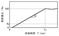
- the control device 7 compares the calculated allowance time T with a set time Ts predetermined for each combustion section. If the allowance time T is equal to or greater than the set time Ts (for example, 30 sec), the furnace temperature of each combustion section is individually set. A normal operation is performed to adjust the combustion amount of the burner 8 so that the set temperature is set to. However, when the surplus time T becomes equal to or shorter than the set time Ts, the control device 7 adjusts the combustion amount of the burner 8 in the combustion section according to the surplus time T according to the profile shown in FIG.
- the combustion amount profile is defined as a ratio (combustion amount ratio) in which the combustion amount of the burner 8 when the control device 7 recognizes that the margin time T has become equal to or less than the set time Ts is 100%.
- the margin time T when the margin time T is equal to or shorter than the set time Ts, the remaining amount of the length of the strip material 4 that can be adjusted in the looper 2 is reduced, and the margin time T is further reduced, the profile shown in FIG. Therefore, the amount of combustion in each combustion section is reduced.
- the control device 7 slows the rotation speed of the transport roller 11 so that the final temperature of the strip material 4 does not decrease. This control acts to suppress a decrease in the margin time T in order to reduce the conveying speed of the strip material 4 in the heating furnace 3.
- the conveying speed of the strip material 4 in the heating furnace 3 is slower than the conveying speed of the strip material 4 in the welding apparatus 1, the remaining amount of the length of the strip material 4 that can be adjusted in the looper 2 is increased, and the margin time T is increased. To increase. When the allowance time T increases, the combustion amount increases, and the furnace temperature rises, the conveying speed of the strip material 4 in the heating furnace 3 increases.
- the change in the furnace temperature is delayed with respect to the change in the combustion amount due to the heat capacity of the furnace body. Therefore, in the present invention, the furnace temperature is adjusted before the remaining amount of the length of the strip material 4 that can be adjusted in the looper 2 is exhausted by changing the combustion amount according to the margin time T without waiting for the furnace temperature to change.
- the temperature should be lowered below the safe temperature. For this reason, the profile of the set time Ts and the combustion amount must be determined so that the furnace temperature can be lowered to a safe temperature or less in the combustion section having the highest set temperature.
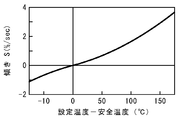
- the combustion amount is proportional to the margin time T, and the slope S is determined according to the difference between the set temperature and the safety temperature of each combustion section, as shown in FIG. Specifically, the higher the set temperature is than the safe temperature, the greater the slope S of the combustion amount profile and the greater the change rate of the combustion amount.
- the slope S becomes a negative value, and when the margin time T decreases, the combustion amount increases. In this case, the amount of combustion predicted when the margin time T becomes zero needs to be smaller than the amount of combustion predicted that the furnace temperature becomes the safe temperature.
- Such a setting of the slope S is predicted that the furnace temperature becomes the safe temperature when the combustion amount of each combustion section continues as the combustion amount corresponding to the safe temperature, that is, for a certain period of time, as the margin time T decreases. Approach the amount of combustion.
- the slope S may be a positive value when the set temperature is lower than the safe temperature.
- the profile is not limited to a linear one, and a curved line may be drawn.
- the control of the burners 8 in all the combustion sections is simultaneously switched from the normal PID control to the control according to the margin time, so that the control can be easily transferred. It is.
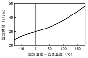
- the set time Ts may be set to a different value for each combustion section. Specifically, as illustrated in FIG. 5, the set time Ts may be set to a longer time as the difference between the set temperature of each combustion section and the safety temperature is larger. In this case, the slope S of the combustion amount ratio profile may be set to the same value in all combustion sections.
- the slope S of the profile is determined so that the actual rate of change of the combustion amount in each combustion section becomes equal, and the followability of the furnace temperature with respect to the margin time is made equal.
- the profile shown in FIG. 3 changes linearly until the combustion amount becomes zero, but when the combustion amount is less than the lower limit value Rc corresponding to the lower limit combustion amount that can maintain the combustion with the actual burner 8, the lower limit is set. It is necessary to maintain the combustion amount of the value Rc or stop the combustion completely. If combustion of the burner 8 is completely stopped, re-ignition requires time and effort. Therefore, when the combustion amount ratio corresponding to the margin time T is equal to or less than the lower limit value Rc, combustion is maintained at the lower limit value Rc, the margin time T becomes zero, and the conveying speed of the strip material 4 in the heating furnace 3 is increased. The combustion of the burner 8 may be stopped at the same time as zero.
- the combustion amount ratio corresponding to the margin time T is equal to or less than the lower limit value Rc
- the combustion amount ratio corresponding to the margin time T is equal to or less than the lower limit value Rc
- the combustion of the burner 8 may be maintained at the lower limit value Rc.
- a threshold value less than the lower limit value Rc is set and the combustion amount ratio is less than or equal to the lower limit value Rc
- the combustion of the lower limit value Rc is maintained or combustion is completely stopped depending on the magnitude relationship between the combustion amount ratio and the threshold value. You may decide whether to do it.
- the welding apparatus 1 is connected to the heating furnace 3 via the looper 2, but the present invention can also be applied to the case where another apparatus is connected via the looper 2.
- the present invention can also be applied to a case where another device is connected to the downstream side of the heating furnace via a looper.
Landscapes
- Engineering & Computer Science (AREA)
- Chemical & Material Sciences (AREA)
- Mechanical Engineering (AREA)
- General Engineering & Computer Science (AREA)
- Crystallography & Structural Chemistry (AREA)
- Thermal Sciences (AREA)
- Physics & Mathematics (AREA)
- Materials Engineering (AREA)
- Metallurgy (AREA)
- Organic Chemistry (AREA)
- Heat Treatment Of Strip Materials And Filament Materials (AREA)
- Control Of Heat Treatment Processes (AREA)
- Regulation And Control Of Combustion (AREA)
Description
本発明は、連続加熱装置に関する。
ストリップ材を連続的に加熱する加熱炉において、ストリップ材の最終到達温度は、炉温だけでなくストリップ材の搬送速度によっても変化する。そのような加熱炉と、他の装置、例えば、リールで供給される一定長のストリップ材を接続して加熱炉に連続供給するための溶接装置が直列に設けられた連続加熱装置では、特許文献1~4に記載されているように、加熱炉と他の装置とのストリップ材の搬送速度の差を吸収するバッファ装置であるルーパが設けられることが多い。
しかしながら、加熱炉と直列に設けられた他の装置がトラブル等で一定時間以上停止すると、ルーパでは吸収しきれず、加熱炉の運転を停止する必要がある。マルテンサイト系ステンレス製のストリップ材等は、通常運転時の炉温の加熱炉内に停止させると、最終到達目標温度よりも高い温度に熱せられ、組成変化して脆化するので、ストリップ材が再起動時等に破断するという問題が生じる。
そこで、従来の連続加熱装置では、ルーパのバッファ量が少なくなると、加熱炉の燃焼を停止して、ストリップ材が脆化しない安全温度まで炉温を低下させている。加熱炉の燃焼を停止してから炉温が安全温度まで低下するまでの間は、ストリップ材の搬送を停止することができないため、この間に加熱炉を通過したストリップ材は製品化できない。また、加熱炉の燃焼を完全に停止すると、燃焼を再開するためには時間がかかるため、ダウンタイムが大きくなるという問題も生じる。
前記問題点に鑑みて、本発明の課題は、ルーパの残量が減少してもストリップ材の適切な加熱を極力継続しながら、ルーパの残量がなくなって加熱炉を停止する際には炉温を安全温度以下に確実に低下できる連続加熱装置を提供することを課題とする。
前記課題を解決するために、本発明による連続加熱装置は、それぞれ独立して燃焼量を制御できる直列に並んだ複数の燃焼区分を有し、ストリップ材を連続的に加熱し、前記ストリップ材の最終到達温度が所定の目標温度になるように前記ストリップ材の搬送速度が調節される加熱炉と、前記加熱炉と直列に配設されて前記ストリップ材が通過し、内部に滞留する前記ストリップ材の長さを調節できるルーパと、前記ルーパが調節できる前記ストリップ材の長さの残量を前記加熱炉における前記ストリップ材の搬送速度で除した余裕時間に応じてそれぞれの前記燃焼区分の燃焼量を制御する制御装置とを有し、前記制御装置は、前記燃焼区分のそれぞれについて、前記余裕時間が所定の設定時間以上であれば、当該燃焼区分の内部温度が予め設定された設定温度になるように当該燃焼区分の燃焼量を調節し、前記余裕時間が前記設定時間以下であれば、当該燃焼区分の燃焼量を前記余裕時間に対する所定のプロファイルで変化させるものとする。
この構成によれば、余裕時間が短くなると、燃焼量を小さくして、燃焼量の減少により炉温が低下した分だけストリップ材の速度を低下させる。このように、ルーパのバッファ量が少なくなるのにしたがって、燃焼量を小さくして、炉温を停止時にもストリップ材を破断させない安全温度に近づけるとともに、可能な限り加熱炉の完全停止を防止して、製造を継続できる。
また、本発明の連続加熱装置において、前記プロファイルは、前記設定温度が高いほど大きな低下率で燃焼量を変化させてもよい。
この構成によれば、設定温度が低い燃焼区分の燃焼量は大きく低下しないので、加熱炉全体の熱量の低下を抑制できる。
また、本発明の連続加熱装置において、前記設定時間は、全ての前記燃焼区分で同一であってもよい。
この構成によれば、また、炉温を設定温度に近づける燃焼量の制御と余裕時間に応じたプロファイルで燃焼量を変化させる制御との切り替えを全ての燃焼区分で同時に行うことになるので、制御の移行が容易である。
また、本発明の連続加熱装置において、前記設定時間は、前記設定温度が高いほど長い時間であってもよい。
この構成によれば、設定温度が高い燃焼区分は、早いタイミングで燃焼量の低下を開始するので、余裕時間の減少による燃焼量の低下と、炉温の低下に応じたライン速度の低下による余裕時間の増加作用とのバランスを最適化でき、ライン停止時に確実に炉温を低下させられる。
また、本発明の連続加熱装置において、前記プロファイルは、前記余裕時間が少ないほど、前記燃焼区分の燃焼量を所定の安全温度に対応する燃焼量に近づけてもよい。
この構成によれば、設定温度が安全温度よりも低い場合には、余裕時間の減少に応じて炉温を高くする。このため、加熱炉全体の熱量の低下による製造量(ストリップ材の搬送速度)の低下を最小限に留められる。
また、本発明の連続加熱装置において、前記制御装置は、前記余裕時間が前記設定時間以下であるとき、前記燃焼区分のそれぞれの燃焼量を、前記余裕時間が前記設定時間になったときの当該燃焼区分の燃焼量を基準に定めてもよい。
この構成によれば、余裕時間が十分に長い場合には、PID制御のような通常の炉温制御を行い、余裕時間が短いときには、炉体の熱容量に起因する遅れが生じない燃焼量の制御に連続的に移行できる。
また、本発明の連続加熱装置において、前記制御装置は、前記燃焼区分の前記余裕時間に応じた燃焼量が所定の下限値以下である場合、前記ルーパを介して接続した設備が完全に停止していなければ前記燃焼区分の燃焼量を前記下限値に設定し、前記ルーパを介して接続した設備が完全に停止していれば前記燃焼区分の燃焼を停止してもよい。
この構成によれば、ルーパを介して接続した設備が稼働していれば、各燃焼区分の燃焼を維持し、余裕時間が増加したときに燃焼装置の再点火のための時間や労力を必要とせず、加熱炉を容易に再起動できる。
以上のように、本発明によれば、加熱炉の燃焼量を、ルーパによるストリップ材の調節量の残量をストリップ材の搬送速度で除した余裕時間に応じて変化させるので、加熱炉の運転を極力停止することなく、また、加熱炉の停止時に炉温を十分に下げられる。
これより、本発明の実施形態について、図面を参照しながら説明する。図1に、本発明の1つの実施形態である、連続加熱装置の構成を示す。この連続加熱装置は、溶接装置1、ルーパ2および加熱炉3がこの順番で配置され、ストリップ材4が連続して挿通される。
本実施形態の連続加熱装置において、ストリップ材4は、リール5の形態で供給される。溶接装置1は、先のリール5のストリップ材4の後端に次のリール5のストリップ材4の先端を溶接するものである。
ルーパ2は、溶接装置1の下流側に配置され、図1中矢印方向に移動可能な可動ローラ6により、内部に滞留するストリップ材4の長さを調節でき、それにより、上流側(溶接装置1)におけるストリップ材4の搬送速度と下流側(加熱炉3)におけるストリップ材4の搬送速度とを異ならせ得る。
加熱炉3は、ルーパ2の下流側に配置され、複数の燃焼区分H1~H8に分割され、動作を制御する制御装置7を有する。燃焼区分H1~H8は、それぞれ、1以上のバーナ8と、炉内の温度を検出する炉温センサ9とを有する。制御装置7は、通常運転時には、例えば図2に示すように、各燃焼区分の炉温が個別に設定された設定温度になるように、公知のPID制御等によって、バーナ8の燃焼量を制御する。尚、図2には、ストリップ材4を停止して炉内に長時間放置してもストリップ材4が脆化して再起動時の張力等によって破断することがない安全温度も示されている。
図1に戻ると、加熱炉3は、最下流においてストリップ材4の最終到達温度を検出する品温センサ10と、ストリップ材4の搬送速度を定める搬送ローラ11とをさらに有する。制御装置7は、品温センサ10によって検出した最終到達温度が予め設定した目標温度になるように、公知のPID制御等によって、搬送ローラ11の速度を制御する。
また、本実施形態の連続加熱装置は、ルーパ2の可動ローラ6の位置を検出する位置検出器12を有し、制御装置7において、ルーパ2が調節できるストリップ材4の長さの残量、つまり、その時点で溶接装置1が完全に停止した場合に、加熱炉3に続けて供給できるストリップ材4の長さを算出できる。さらに、制御装置7は、ルーパ2が調節できるストリップ材4の長さの残量を、搬送ローラ11の回転数に比例する加熱炉3におけるストリップ材4の搬送速度で除した余裕時間Tを算出する。
制御装置7は、算出した余裕時間Tを燃焼区分毎に予め定められた設定時間Tsと比較し、余裕時間Tが設定時間Ts(例えば30sec)以上であれば、各燃焼区分の炉温が個別に設定された設定温度になるようにバーナ8の燃焼量を調節する通常の運転を行う。しかしながら、制御装置7は、余裕時間Tが設定時間Ts以下になると、当該燃焼区分のバーナ8の燃焼量を、図3に示すプロファイルにしたがって、余裕時間Tに応じて調節する。燃焼量のプロファイルは、制御装置7において余裕時間Tが設定時間Ts以下になったと認識した時点でのバーナ8の燃焼量を100%とする比率(燃焼量比)として定められている。これにより、外気の温度や湿度により炉温と燃焼量との関係が変化しても、炉温を設定温度に維持する通常の制御から余裕時間Tに応じて燃焼量を定める制御に切り替える際に燃焼量が急変することを防止できる。勿論、燃焼量の絶対量のプロファイルを規定してもよい。
本実施形態において、余裕時間Tが設定時間Ts以下であるときに、ルーパ2において調節できるストリップ材4の長さの残量が減少して余裕時間Tがさらに減少すると、図3に示すプロファイルにしたがって各燃焼区分の燃焼量が減少する。燃焼量が減少すると、炉温が低下するので、ストリップ材4の最終到達温度が低下しようとする。制御装置7は、ストリップ材4の最終到達温度が低下しないように、搬送ローラ11の回転速度を遅くする。この制御は、加熱炉3におけるストリップ材4の搬送速度を低下させるため、余裕時間Tの減少を抑制するように作用する。
加熱炉3におけるストリップ材4の搬送速度が、溶接装置1におけるストリップ材4の搬送速度よりも遅い場合、ルーパ2において調節できるストリップ材4の長さの残量が増大して、余裕時間Tが増加する。余裕時間Tが増加して燃焼量が増大し、炉温が上昇すると、加熱炉3におけるストリップ材4の搬送速度が上昇する。
炉温の変化は、炉体の熱容量等により、燃焼量の変化に対して遅れて生じる。よって、本発明では、炉温の変化を待たず、余裕時間Tに応じて燃焼量を変化させることで、ルーパ2において調節できるストリップ材4の長さの残量がなくなる前に、炉温を安全温度以下に低下させられるようにする。このため、設定時間Tsおよび燃焼量のプロファイルは、最も設定温度が高い燃焼区分において、炉温を安全温度以下に低下させられるように定めなければならない。
本実施形態では、燃焼量は、余裕時間Tに比例し、その傾きSが、図4に示すように、各燃焼区分の設定温度と安全温度との差に応じて定められる。詳しくは、設定温度が安全温度よりも高いほど、燃焼量プロファイルの傾きSが大きく、燃焼量の変化率が大きくなる。本実施例では、設定温度が安全温度よりも低い場合は、傾きSが負の値となり、余裕時間Tが減少すると燃焼量が増大するようになっている。この場合、余裕時間Tがゼロになった場合に予測される燃焼量が、炉温が安全温度になると予測される燃焼量よりも小さくなる必要がある。このような傾きSの設定は、それぞれの燃焼区分の燃焼量を、余裕時間Tの減少にしたがって、安全温度に対応する燃焼量、つまり、一定時間以上継続すると炉温が安全温度になると予測される燃焼量に近づける。これにより、加熱炉3全体における燃焼量の余裕時間Tの減少に対する減少を抑制し、ストリップ材4の搬送速度の低下を最小限に留められる。また、設定温度が安全温度よりも低い場合にも、傾きSが正の値となるようにしてもよい。また、プロファイルは直線的なものに限らず、曲線を描いてもよい。
設定時間Tsを全ての燃焼区分で等しい値に設定すれば、全ての燃焼区分のバーナ8の制御が、通常のPID制御から、余裕時間に応じた制御に一斉に切り替わるので、制御の移行が容易である。しかしながら、設定時間Tsを燃焼区分毎に異なる値に設定してもよい。具体的には、設定時間Tsは、図5に例示するように、各燃焼区分の設定温度と安全温度との差が大きいほど長い時間に設定するとよい。この場合、燃焼量比のプロファイルの傾きSを、全ての燃焼区分で同じ値にしてもよい。また、特に燃焼区分の構造が等しい場合には、各燃焼区分の実際の燃焼量の変化率が等しくなるようにプロファイルの傾きSを定めて、余裕時間に対する炉温の追従性を同等にするとよい。
また、図3に示すプロファイルは、燃焼量がゼロになるまで直線的に変化しているが、実際のバーナ8で燃焼を維持できる下限燃焼量に相当する下限値Rc以下の場合には、下限値Rcの燃焼量を維持するか、完全に燃焼を停止する必要がある。バーナ8の燃焼を完全に停止すると、再点火には手間と時間が必要となる。そこで、余裕時間Tに対応する燃焼量比が下限値Rc以下である場合には、下限値Rcで燃焼を維持し、余裕時間Tがゼロになり、加熱炉3におけるストリップ材4の搬送速度をゼロにすると同時にバーナ8の燃焼を完全に停止するようにしてもよい。また、余裕時間Tに対応する燃焼量比が下限値Rc以下である場合には、溶接装置1が完全に停止しているときのみ、まもなく余裕時間Tがゼロになる蓋然性が高いので、バーナ8の燃焼を完全に停止し、溶接装置1が少しでも動いていれば、余裕時間Tが増大する可能性があるので、下限値Rcでバーナ8の燃焼を維持するようにしてもよい。また、下限値Rc以下の閾値を設定し、燃焼量比が下限値Rc以下である場合には、燃焼量比と閾値との大小関係により下限値Rcの燃焼を維持するか完全に燃焼を停止するかを決定してもよい。
尚、本実施形態では、加熱炉3にルーパ2を介して溶接装置1が接続されているが、ルーパ2を介して他の装置を接続する場合にも、本発明が適用できる。また、本発明は、加熱炉の下流側に、ルーパを介して他の装置を接続する場合にも適用できる。加熱炉の上流側と下流側の両方にルーパを設ける場合、両方のルーパについて余裕時間を算出し、短い方の余裕時間に基づいて加熱炉の燃焼量を制御すればよい。
1…溶接装置
2…ルーパ
3…加熱炉
4…ストリップ材
5…リール
6…可動ローラ
7…制御装置
8…バーナ
9…炉温センサ
10…品温センサ
11…搬送ローラ
12…位置検出器
2…ルーパ
3…加熱炉
4…ストリップ材
5…リール
6…可動ローラ
7…制御装置
8…バーナ
9…炉温センサ
10…品温センサ
11…搬送ローラ
12…位置検出器
Claims (7)
- それぞれ独立して燃焼量を制御できる直列に並んだ複数の燃焼区分を有し、ストリップ材を連続的に加熱し、前記ストリップ材の最終到達温度が所定の目標温度になるように前記ストリップ材の搬送速度が調節される加熱炉と、
前記加熱炉と直列に配設されて前記ストリップ材が通過し、内部に滞留する前記ストリップ材の長さを調節できるルーパと、
前記ルーパが調節できる前記ストリップ材の長さの残量を前記加熱炉における前記ストリップ材の搬送速度で除した余裕時間に応じてそれぞれの前記燃焼区分の燃焼量を制御する制御装置とを有し、
前記制御装置は、前記燃焼区分のそれぞれについて、前記余裕時間が所定の設定時間以上であれば、当該燃焼区分の内部温度が予め設定された設定温度になるように当該燃焼区分の燃焼量を調節し、前記余裕時間が前記設定時間以下であれば、当該燃焼区分の燃焼量を前記余裕時間に対する所定のプロファイルで変化させることを特徴とする連続加熱装置。 - 前記プロファイルは、前記設定温度が高いほど、大きな低下率で燃焼量を変化させることを特徴とする請求項1に記載の連続加熱装置。
- 前記設定時間は、全ての前記燃焼区分で同一であることを特徴とする請求項2に記載の連続加熱装置。
- 前記設定時間は、前記設定温度が高いほど長い時間であることを特徴とする請求項1に記載の連続加熱装置。
- 前記プロファイルは、前記余裕時間が少ないほど、前記燃焼区分の燃焼量を所定の安全温度に対応する燃焼量に近づけるものであることを特徴とする請求項1から4のいずれかに記載の連続加熱装置。
- 前記制御装置は、前記余裕時間が前記設定時間以下であるとき、前記燃焼区分のそれぞれの燃焼量を、前記余裕時間が前記設定時間になったときの当該燃焼区分の燃焼量を基準に定めることを特徴とする請求項1から4のいずれかに記載の連続加熱装置。
- 前記制御装置は、前記燃焼区分の前記余裕時間に応じた燃焼量が所定の下限値以下である場合、前記ルーパを介して接続した設備が完全に停止していなければ前記燃焼区分の燃焼量を前記下限値に設定し、前記ルーパを介して接続した設備が完全に停止していれば前記燃焼区分の燃焼を停止することを特徴とする請求項1から4のいずれかに記載の連続加熱装置。
Priority Applications (5)
| Application Number | Priority Date | Filing Date | Title |
|---|---|---|---|
| JP2012551429A JP5189230B1 (ja) | 2012-07-06 | 2012-07-06 | 連続加熱装置 |
| CN201280001715.8A CN103764856B (zh) | 2012-07-06 | 2012-07-06 | 连续加热装置的控制方法 |
| ES12816425T ES2571595T3 (es) | 2012-07-06 | 2012-07-06 | Dispositivo de calentamiento continuo |
| EP12816425.8A EP2701121B1 (en) | 2012-07-06 | 2012-07-06 | Continuous heating device |
| PCT/JP2012/067364 WO2014006749A1 (ja) | 2012-07-06 | 2012-07-06 | 連続加熱装置 |
Applications Claiming Priority (1)
| Application Number | Priority Date | Filing Date | Title |
|---|---|---|---|
| PCT/JP2012/067364 WO2014006749A1 (ja) | 2012-07-06 | 2012-07-06 | 連続加熱装置 |
Publications (1)
| Publication Number | Publication Date |
|---|---|
| WO2014006749A1 true WO2014006749A1 (ja) | 2014-01-09 |
Family
ID=48481460
Family Applications (1)
| Application Number | Title | Priority Date | Filing Date |
|---|---|---|---|
| PCT/JP2012/067364 Ceased WO2014006749A1 (ja) | 2012-07-06 | 2012-07-06 | 連続加熱装置 |
Country Status (5)
| Country | Link |
|---|---|
| EP (1) | EP2701121B1 (ja) |
| JP (1) | JP5189230B1 (ja) |
| CN (1) | CN103764856B (ja) |
| ES (1) | ES2571595T3 (ja) |
| WO (1) | WO2014006749A1 (ja) |
Families Citing this family (4)
| Publication number | Priority date | Publication date | Assignee | Title |
|---|---|---|---|---|
| JP7048721B2 (ja) * | 2018-03-23 | 2022-04-05 | Primetals Technologies Japan株式会社 | 熱処理炉の運転支援装置及び運転支援方法並びに熱処理設備及びその運転方法 |
| CN115786686B (zh) * | 2022-11-17 | 2025-12-05 | 攀钢集团西昌钢钒有限公司 | 连续退火炉故障停机时抑制带钢热瓢曲的控制方法及系统 |
| EP4481309A1 (en) * | 2023-06-19 | 2024-12-25 | Alite GmbH | Idc - indirect calciner |
| DE102024126517A1 (de) * | 2024-09-13 | 2026-03-19 | Maschinenfabrik Niehoff Gmbh & Co Kg | Drahtdurchlaufglühe und Verfahren zur Regelung der Temperatur des Drahtes in der Drahtdurchlaufglühe |
Citations (5)
| Publication number | Priority date | Publication date | Assignee | Title |
|---|---|---|---|---|
| JPH0679329A (ja) | 1992-09-04 | 1994-03-22 | Nippon Steel Corp | ストリップ連続処理ラインの水平ルーパー装置 |
| JP2007203363A (ja) | 2006-02-06 | 2007-08-16 | Sumitomo Metal Ind Ltd | 鋼帯の処理方法及び処理設備 |
| JP2007291472A (ja) | 2006-04-27 | 2007-11-08 | Nippon Steel Corp | 合金化溶融亜鉛メッキ鋼帯の製造方法 |
| JP2011084753A (ja) | 2009-10-13 | 2011-04-28 | Nippon Steel Corp | 連続焼鈍設備の加熱炉の板温度制御方法 |
| JP2011157590A (ja) * | 2010-02-01 | 2011-08-18 | Nippon Steel Corp | 連続焼鈍炉の板温制御装置および板温制御方法 |
Family Cites Families (1)
| Publication number | Priority date | Publication date | Assignee | Title |
|---|---|---|---|---|
| CN102409155A (zh) * | 2011-11-15 | 2012-04-11 | 江苏赛福天钢索股份有限公司 | 热处理炉温模糊控制系统 |
-
2012
- 2012-07-06 CN CN201280001715.8A patent/CN103764856B/zh not_active Expired - Fee Related
- 2012-07-06 JP JP2012551429A patent/JP5189230B1/ja active Active
- 2012-07-06 WO PCT/JP2012/067364 patent/WO2014006749A1/ja not_active Ceased
- 2012-07-06 ES ES12816425T patent/ES2571595T3/es active Active
- 2012-07-06 EP EP12816425.8A patent/EP2701121B1/en not_active Not-in-force
Patent Citations (5)
| Publication number | Priority date | Publication date | Assignee | Title |
|---|---|---|---|---|
| JPH0679329A (ja) | 1992-09-04 | 1994-03-22 | Nippon Steel Corp | ストリップ連続処理ラインの水平ルーパー装置 |
| JP2007203363A (ja) | 2006-02-06 | 2007-08-16 | Sumitomo Metal Ind Ltd | 鋼帯の処理方法及び処理設備 |
| JP2007291472A (ja) | 2006-04-27 | 2007-11-08 | Nippon Steel Corp | 合金化溶融亜鉛メッキ鋼帯の製造方法 |
| JP2011084753A (ja) | 2009-10-13 | 2011-04-28 | Nippon Steel Corp | 連続焼鈍設備の加熱炉の板温度制御方法 |
| JP2011157590A (ja) * | 2010-02-01 | 2011-08-18 | Nippon Steel Corp | 連続焼鈍炉の板温制御装置および板温制御方法 |
Non-Patent Citations (1)
| Title |
|---|
| See also references of EP2701121A4 * |
Also Published As
| Publication number | Publication date |
|---|---|
| EP2701121B1 (en) | 2016-04-27 |
| CN103764856A (zh) | 2014-04-30 |
| CN103764856B (zh) | 2015-11-25 |
| ES2571595T3 (es) | 2016-05-26 |
| JP5189230B1 (ja) | 2013-04-24 |
| EP2701121A4 (en) | 2014-09-03 |
| JPWO2014006749A1 (ja) | 2016-06-02 |
| EP2701121A1 (en) | 2014-02-26 |
Similar Documents
| Publication | Publication Date | Title |
|---|---|---|
| JP5189230B1 (ja) | 連続加熱装置 | |
| EP2535144A1 (en) | Wire saw | |
| JP6294956B2 (ja) | 巻取りが制御されるスパイラルコンベヤ | |
| CN103361608B (zh) | 蒸镀装置 | |
| US9682882B2 (en) | Methods for producing a glass ribbon | |
| RU2623520C2 (ru) | Устройство и способ непрерывной обработки металлической ленты | |
| JP2017534553A5 (ja) | ||
| KR101962551B1 (ko) | 텐션 제어 장치 및 반송 장치 | |
| JP5144963B2 (ja) | 鋼帯連続熱処理炉の温度制御方法 | |
| JP2016108150A (ja) | 給紙装置 | |
| JP7578113B2 (ja) | 走間板厚変更設定制御方法および走間板厚変更設定制御装置 | |
| JP6552085B2 (ja) | ボイラ給水装置 | |
| JP6417769B2 (ja) | 板状ガラス成形装置及び板状ガラスの成形方法 | |
| JP5742311B2 (ja) | 熱間圧延ラインにおける圧延材の上反り防止方法及び装置 | |
| JP2015210035A (ja) | 炉内圧力調節装置及び炉内圧力調節方法 | |
| JP5226825B2 (ja) | プロセス温度制御方法 | |
| JP5396900B2 (ja) | ヒートバックル防止制御方法および装置 | |
| JP5294012B2 (ja) | 張力制御装置 | |
| JP6354069B2 (ja) | 溶融金属めっき鋼帯の製造方法および溶融金属めっき鋼帯の製造ライン | |
| JPS63119922A (ja) | 圧延間ピツチの制御方法 | |
| KR102046953B1 (ko) | 사이드 트리머의 나이프 오일공급장치 및 오일공급방법 | |
| JP2019018237A (ja) | 厚板材の圧延装置、圧延方法及び厚鋼板の製造方法 | |
| JPH0610845A (ja) | 可変速給水装置 | |
| JP3891690B2 (ja) | 灰溶融方法とその灰溶融炉 | |
| JP2023014541A (ja) | プロセスライン制御システム |
Legal Events
| Date | Code | Title | Description |
|---|---|---|---|
| ENP | Entry into the national phase |
Ref document number: 2012551429 Country of ref document: JP Kind code of ref document: A |
|
| WWE | Wipo information: entry into national phase |
Ref document number: 2012816425 Country of ref document: EP |
|
| 121 | Ep: the epo has been informed by wipo that ep was designated in this application |
Ref document number: 12816425 Country of ref document: EP Kind code of ref document: A1 |
|
| NENP | Non-entry into the national phase |
Ref country code: DE |