WO2014006781A1 - 極薄銅箔及びその製造方法、並びに極薄銅層 - Google Patents
極薄銅箔及びその製造方法、並びに極薄銅層 Download PDFInfo
- Publication number
- WO2014006781A1 WO2014006781A1 PCT/JP2012/083531 JP2012083531W WO2014006781A1 WO 2014006781 A1 WO2014006781 A1 WO 2014006781A1 JP 2012083531 W JP2012083531 W JP 2012083531W WO 2014006781 A1 WO2014006781 A1 WO 2014006781A1
- Authority
- WO
- WIPO (PCT)
- Prior art keywords
- copper foil
- layer
- supporting
- ultrathin
- ultra
- Prior art date
- Legal status (The legal status is an assumption and is not a legal conclusion. Google has not performed a legal analysis and makes no representation as to the accuracy of the status listed.)
- Ceased
Links
Images


Classifications
-
- C—CHEMISTRY; METALLURGY
- C25—ELECTROLYTIC OR ELECTROPHORETIC PROCESSES; APPARATUS THEREFOR
- C25D—PROCESSES FOR THE ELECTROLYTIC OR ELECTROPHORETIC PRODUCTION OF COATINGS; ELECTROFORMING; APPARATUS THEREFOR
- C25D7/00—Electroplating characterised by the article coated
- C25D7/06—Wires; Strips; Foils
-
- B—PERFORMING OPERATIONS; TRANSPORTING
- B32—LAYERED PRODUCTS
- B32B—LAYERED PRODUCTS, i.e. PRODUCTS BUILT-UP OF STRATA OF FLAT OR NON-FLAT, e.g. CELLULAR OR HONEYCOMB, FORM
- B32B15/00—Layered products comprising a layer of metal
- B32B15/04—Layered products comprising a layer of metal comprising metal as the main or only constituent of a layer, which is next to another layer of the same or of a different material
- B32B15/08—Layered products comprising a layer of metal comprising metal as the main or only constituent of a layer, which is next to another layer of the same or of a different material of synthetic resin
-
- C—CHEMISTRY; METALLURGY
- C25—ELECTROLYTIC OR ELECTROPHORETIC PROCESSES; APPARATUS THEREFOR
- C25D—PROCESSES FOR THE ELECTROLYTIC OR ELECTROPHORETIC PRODUCTION OF COATINGS; ELECTROFORMING; APPARATUS THEREFOR
- C25D1/00—Electroforming
- C25D1/04—Wires; Strips; Foils
-
- C—CHEMISTRY; METALLURGY
- C25—ELECTROLYTIC OR ELECTROPHORETIC PROCESSES; APPARATUS THEREFOR
- C25D—PROCESSES FOR THE ELECTROLYTIC OR ELECTROPHORETIC PRODUCTION OF COATINGS; ELECTROFORMING; APPARATUS THEREFOR
- C25D1/00—Electroforming
- C25D1/20—Separation of the formed objects from the electrodes with no destruction of said electrodes
- C25D1/22—Separating compounds
-
- C—CHEMISTRY; METALLURGY
- C25—ELECTROLYTIC OR ELECTROPHORETIC PROCESSES; APPARATUS THEREFOR
- C25D—PROCESSES FOR THE ELECTROLYTIC OR ELECTROPHORETIC PRODUCTION OF COATINGS; ELECTROFORMING; APPARATUS THEREFOR
- C25D3/00—Electroplating: Baths therefor
- C25D3/02—Electroplating: Baths therefor from solutions
- C25D3/26—Electroplating: Baths therefor from solutions of cadmium
- C25D3/28—Electroplating: Baths therefor from solutions of cadmium from cyanide baths
-
- C—CHEMISTRY; METALLURGY
- C25—ELECTROLYTIC OR ELECTROPHORETIC PROCESSES; APPARATUS THEREFOR
- C25D—PROCESSES FOR THE ELECTROLYTIC OR ELECTROPHORETIC PRODUCTION OF COATINGS; ELECTROFORMING; APPARATUS THEREFOR
- C25D5/00—Electroplating characterised by the process; Pretreatment or after-treatment of workpieces
- C25D5/10—Electroplating with more than one layer of the same or of different metals
- C25D5/12—Electroplating with more than one layer of the same or of different metals at least one layer being of nickel or chromium
-
- C—CHEMISTRY; METALLURGY
- C25—ELECTROLYTIC OR ELECTROPHORETIC PROCESSES; APPARATUS THEREFOR
- C25D—PROCESSES FOR THE ELECTROLYTIC OR ELECTROPHORETIC PRODUCTION OF COATINGS; ELECTROFORMING; APPARATUS THEREFOR
- C25D5/00—Electroplating characterised by the process; Pretreatment or after-treatment of workpieces
- C25D5/60—Electroplating characterised by the structure or texture of the layers
- C25D5/605—Surface topography of the layers, e.g. rough, dendritic or nodular layers
-
- C—CHEMISTRY; METALLURGY
- C25—ELECTROLYTIC OR ELECTROPHORETIC PROCESSES; APPARATUS THEREFOR
- C25D—PROCESSES FOR THE ELECTROLYTIC OR ELECTROPHORETIC PRODUCTION OF COATINGS; ELECTROFORMING; APPARATUS THEREFOR
- C25D7/00—Electroplating characterised by the article coated
- C25D7/06—Wires; Strips; Foils
- C25D7/0614—Strips or foils
- C25D7/0621—In horizontal cells
-
- C—CHEMISTRY; METALLURGY
- C25—ELECTROLYTIC OR ELECTROPHORETIC PROCESSES; APPARATUS THEREFOR
- C25D—PROCESSES FOR THE ELECTROLYTIC OR ELECTROPHORETIC PRODUCTION OF COATINGS; ELECTROFORMING; APPARATUS THEREFOR
- C25D7/00—Electroplating characterised by the article coated
- C25D7/06—Wires; Strips; Foils
- C25D7/0614—Strips or foils
- C25D7/0635—In radial cells
-
- H—ELECTRICITY
- H05—ELECTRIC TECHNIQUES NOT OTHERWISE PROVIDED FOR
- H05K—PRINTED CIRCUITS; CASINGS OR CONSTRUCTIONAL DETAILS OF ELECTRIC APPARATUS; MANUFACTURE OF ASSEMBLAGES OF ELECTRICAL COMPONENTS
- H05K1/00—Printed circuits
- H05K1/02—Details
- H05K1/09—Use of materials for the conductive, e.g. metallic pattern
-
- C—CHEMISTRY; METALLURGY
- C25—ELECTROLYTIC OR ELECTROPHORETIC PROCESSES; APPARATUS THEREFOR
- C25D—PROCESSES FOR THE ELECTROLYTIC OR ELECTROPHORETIC PRODUCTION OF COATINGS; ELECTROFORMING; APPARATUS THEREFOR
- C25D3/00—Electroplating: Baths therefor
- C25D3/02—Electroplating: Baths therefor from solutions
- C25D3/12—Electroplating: Baths therefor from solutions of nickel or cobalt
-
- C—CHEMISTRY; METALLURGY
- C25—ELECTROLYTIC OR ELECTROPHORETIC PROCESSES; APPARATUS THEREFOR
- C25D—PROCESSES FOR THE ELECTROLYTIC OR ELECTROPHORETIC PRODUCTION OF COATINGS; ELECTROFORMING; APPARATUS THEREFOR
- C25D3/00—Electroplating: Baths therefor
- C25D3/02—Electroplating: Baths therefor from solutions
- C25D3/38—Electroplating: Baths therefor from solutions of copper
-
- H—ELECTRICITY
- H05—ELECTRIC TECHNIQUES NOT OTHERWISE PROVIDED FOR
- H05K—PRINTED CIRCUITS; CASINGS OR CONSTRUCTIONAL DETAILS OF ELECTRIC APPARATUS; MANUFACTURE OF ASSEMBLAGES OF ELECTRICAL COMPONENTS
- H05K2201/00—Indexing scheme relating to printed circuits covered by H05K1/00
- H05K2201/03—Conductive materials
- H05K2201/0332—Structure of the conductor
- H05K2201/0335—Layered conductors or foils
- H05K2201/0355—Metal foils
-
- H—ELECTRICITY
- H05—ELECTRIC TECHNIQUES NOT OTHERWISE PROVIDED FOR
- H05K—PRINTED CIRCUITS; CASINGS OR CONSTRUCTIONAL DETAILS OF ELECTRIC APPARATUS; MANUFACTURE OF ASSEMBLAGES OF ELECTRICAL COMPONENTS
- H05K2203/00—Indexing scheme relating to apparatus or processes for manufacturing printed circuits covered by H05K3/00
- H05K2203/15—Position of the PCB during processing
- H05K2203/1545—Continuous processing, i.e. involving rolls moving a band-like or solid carrier along a continuous production path
-
- H—ELECTRICITY
- H05—ELECTRIC TECHNIQUES NOT OTHERWISE PROVIDED FOR
- H05K—PRINTED CIRCUITS; CASINGS OR CONSTRUCTIONAL DETAILS OF ELECTRIC APPARATUS; MANUFACTURE OF ASSEMBLAGES OF ELECTRICAL COMPONENTS
- H05K3/00—Apparatus or processes for manufacturing printed circuits
- H05K3/02—Apparatus or processes for manufacturing printed circuits in which the conductive material is applied to the surface of the insulating support and is thereafter removed from such areas of the surface which are not intended for current conducting or shielding
- H05K3/022—Processes for manufacturing precursors of printed circuits, i.e. copper-clad substrates
- H05K3/025—Processes for manufacturing precursors of printed circuits, i.e. copper-clad substrates by transfer of thin metal foil formed on a temporary carrier, e.g. peel-apart copper
-
- Y—GENERAL TAGGING OF NEW TECHNOLOGICAL DEVELOPMENTS; GENERAL TAGGING OF CROSS-SECTIONAL TECHNOLOGIES SPANNING OVER SEVERAL SECTIONS OF THE IPC; TECHNICAL SUBJECTS COVERED BY FORMER USPC CROSS-REFERENCE ART COLLECTIONS [XRACs] AND DIGESTS
- Y10—TECHNICAL SUBJECTS COVERED BY FORMER USPC
- Y10T—TECHNICAL SUBJECTS COVERED BY FORMER US CLASSIFICATION
- Y10T428/00—Stock material or miscellaneous articles
- Y10T428/12—All metal or with adjacent metals
- Y10T428/12431—Foil or filament smaller than 6 mils
- Y10T428/12438—Composite
-
- Y—GENERAL TAGGING OF NEW TECHNOLOGICAL DEVELOPMENTS; GENERAL TAGGING OF CROSS-SECTIONAL TECHNOLOGIES SPANNING OVER SEVERAL SECTIONS OF THE IPC; TECHNICAL SUBJECTS COVERED BY FORMER USPC CROSS-REFERENCE ART COLLECTIONS [XRACs] AND DIGESTS
- Y10—TECHNICAL SUBJECTS COVERED BY FORMER USPC
- Y10T—TECHNICAL SUBJECTS COVERED BY FORMER US CLASSIFICATION
- Y10T428/00—Stock material or miscellaneous articles
- Y10T428/24—Structurally defined web or sheet [e.g., overall dimension, etc.]
- Y10T428/24802—Discontinuous or differential coating, impregnation or bond [e.g., artwork, printing, retouched photograph, etc.]
- Y10T428/24917—Discontinuous or differential coating, impregnation or bond [e.g., artwork, printing, retouched photograph, etc.] including metal layer
Definitions
- the present invention relates to an ultrathin copper foil, a manufacturing method thereof, and an ultrathin copper layer. More specifically, the present invention relates to an ultrathin copper foil used as a material for printed wiring boards for fine pattern applications, a method for producing the same, and an ultrathin copper layer.
- a general method for forming microcircuits is to form a wiring circuit on an ultrathin copper layer, and then remove the ultrathin copper layer by etching with a sulfuric acid-hydrogen peroxide etchant (MSAP: Modified-Semi-Additive-Process). ). Therefore, it is preferable that the ultrathin copper layer has a uniform thickness.
- a general method for forming an ultrathin copper layer is to form a release layer on a supporting copper foil (12 to 70 ⁇ m), and then form an ultrathin copper layer (0.5 to 10.0 ⁇ m) and roughened particles on the surface.
- the steps after the formation of the supporting copper foil have been carried out using a ninety-fold folding method that does not support the supporting copper foil with a drum as shown in FIG. 1 (Patent Document 1).
- the thickness accuracy of the ultra-thin copper layer formed by electrolytic plating is greatly affected by the distance between the anode and the cathode.
- this invention makes it the subject to provide the ultra-thin copper foil which improved the thickness precision of the ultra-thin copper layer on support copper foil.
- the present inventor has conducted earnest research, paying attention to the carrying method of the process after the supporting copper foil, and using the carrying method using the drum as a supporting medium instead of the ninety-five folding, It was found that the distance between the electrodes can be ensured and the thickness accuracy of the ultrathin copper layer can be improved.
- the present invention has been completed on the basis of the above knowledge.
- the present invention includes a supporting copper foil, a peeling layer laminated on the supporting copper foil, and an ultrathin copper layer laminated on the peeling layer. It is an ultra-thin copper foil, and the thickness accuracy of the ultra-thin copper layer measured by the weight-thickness method is 3.0% or less.
- the present invention is an ultrathin copper foil comprising a support copper foil, a release layer laminated on the support copper foil, and an ultrathin copper layer laminated on the release layer, It is an ultrathin copper foil whose thickness accuracy of the ultrathin copper layer measured by the four probe method is 10.0% or less.
- a roughened particle layer is provided on the surface of the ultrathin copper layer.
- the surface of the long support copper foil conveyed in the length direction by the roll-to-roll conveyance method is treated on the support copper foil and the support copper foil.
- This is a method for producing an ultrathin copper foil comprising a laminated release layer and an ultrathin copper layer laminated on the release layer, and the release layer is formed on the surface of the supporting copper foil conveyed by a conveyance roll.
- An ultrathin copper foil including a step and a step of forming an ultrathin copper layer on the surface of the release layer by electroplating while supporting the support copper foil on which the release layer transported by a transport roll is formed with a drum It is a manufacturing method.
- the manufacturing method of the ultra-thin copper foil of this invention is one Embodiment.
- WHEREIN The process of forming the said peeling layer is the said support copper foil surface by electroplating, supporting the said support copper foil conveyed with a conveyance roll with a drum. This is done by forming an ultrathin copper layer.
- the method for producing an ultrathin copper foil of the present invention further includes a step of forming a roughened particle layer on the surface of the ultrathin copper layer of the supporting copper foil that is transported by a transport roll.
- the step of forming the roughened particle layer is performed by electrolytic plating while supporting the supporting copper foil transported by a transport roll with a drum. This is done by forming a roughened particle layer on the surface of the ultrathin copper layer.
- an electrode made of an electrolytic copper foil is laminated on a release layer laminated on a support copper foil to form an ultrathin copper foil together with the support copper foil and the release layer.
- the thin copper layer is an ultrathin copper layer having a thickness accuracy of 3.0% or less as measured by a weight-thickness method.
- an electrode made of an electrolytic copper foil is laminated on a release layer laminated on a support copper foil to form an ultrathin copper foil together with the support copper foil and the release layer. It is a thin copper layer, and is an ultrathin copper layer having a thickness accuracy of 10.0% or less measured by the four-probe method.
- the ultrathin copper layer of the present invention is laminated on a release layer laminated on a support copper foil, and constitutes an ultrathin copper foil together with the support copper foil and the release layer. It is an ultra-thin copper layer made of foil, and has a roughened particle layer on the surface.
- the present invention is a printed wiring board manufactured using the ultrathin copper foil of the present invention.
- the present invention is a printed wiring board using the ultrathin copper layer of the present invention.
- an ultrathin copper foil in which the thickness accuracy of the ultrathin copper layer on the supporting copper foil is improved.
- the supporting copper foil that can be used in the present invention is typically provided in the form of a rolled copper foil or an electrolytic copper foil.
- the electrolytic copper foil is produced by electrolytic deposition of copper from a copper sulfate plating bath onto a drum of titanium or stainless steel, and the rolled copper foil is produced by repeating plastic working and heat treatment with a rolling roll.
- the copper foil material is, for example, Sn-containing copper, Ag-containing copper, copper alloy added with Cr, Zr, Mg, etc., and Corson-based added with Ni, Si, etc. Copper alloys such as copper alloys can also be used.
- a copper alloy foil is also included.
- the thickness of the support copper foil which can be used for this invention, What is necessary is just to adjust suitably to the thickness suitable for fulfill
- a release layer is provided on the supporting copper foil.
- the release layer can be formed using nickel, a nickel-phosphorus alloy, a nickel-cobalt alloy, chromium, or the like.
- the release layer is the part that peels off when the supporting copper foil is peeled off from the ultrathin copper layer, but it can also have a barrier effect that prevents the copper component from diffusing from the supporting copper foil into the ultrathin copper layer. it can.
- an electrolytic copper foil is used as the supporting copper foil, it is preferable to provide a release layer on the low roughness surface from the viewpoint of reducing pinholes.
- the release layer can be provided using a method such as plating, sputtering, CVD, or physical vapor deposition.
- Ultra-thin copper layer An ultrathin copper layer is provided on the release layer.
- the ultra-thin copper layer can be formed by electroplating using an electrolytic bath such as copper sulfate, copper pyrophosphate, copper sulfamate, copper cyanide, etc., and is used in general electrolytic copper foil with high current density. Since a copper foil can be formed, a copper sulfate bath is preferable.
- the thickness of the ultrathin copper layer is not particularly limited, but is generally thinner than the supporting copper foil, for example, 12 ⁇ m or less. Typically, it is 0.5 to 10 ⁇ m, and more typically 1 to 5 ⁇ m.
- a roughened particle layer may be provided on the surface of the ultrathin copper layer by performing a roughening treatment in order to improve adhesion to the insulating substrate, for example.
- the roughening treatment can be performed, for example, by forming roughened particles with copper or a copper alloy.
- the roughening process may be fine.
- the roughened particle layer may be a single layer selected from the group consisting of copper, nickel, cobalt, and zinc, or a layer made of an alloy containing at least one of them.
- secondary particles, tertiary particles and / or rust preventive layers are formed of nickel, cobalt, copper, zinc alone or an alloy, and further on the surface.
- Treatments such as chromate treatment and silane coupling treatment may be applied. That is, one or more layers selected from the group consisting of a rust preventive layer, a chromate treatment layer and a silane coupling treatment layer may be formed on the surface of the roughened particle layer, and on the surface of the ultrathin copper layer, You may form 1 or more types of layers selected from the group which consists of a rust prevention layer, a chromate treatment layer, and a silane coupling treatment layer.
- the ultrathin copper foil includes a supporting copper foil, a release layer formed on the support copper foil, and an ultrathin copper layer laminated on the release layer.
- the method of using the ultrathin copper foil itself is well known to those skilled in the art.
- the surface of the ultrathin copper layer is made of paper base phenolic resin, paper base epoxy resin, synthetic fiber cloth base epoxy resin, glass cloth / paper composite.
- the copper layer can be etched into the intended conductor pattern to finally produce a printed wiring board.
- the peeling site is mainly the interface between the peeling layer and the ultrathin copper layer.
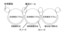
- FIG. 2 is a schematic diagram showing a foil handling method according to the method for manufacturing an ultrathin copper foil according to Embodiment 1 of the present invention.
- the manufacturing method of the ultra-thin copper foil which concerns on Embodiment 1 of this invention is processing support copper foil by processing the surface of the elongate support copper foil conveyed in a length direction by a roll-to-roll conveyance system. And an ultrathin copper foil comprising a peeling layer laminated on a supporting copper foil and an ultrathin copper layer laminated on the peeling layer.
- the manufacturing method of the ultra-thin copper foil which concerns on Embodiment 1 of this invention is the process of forming an ultra-thin copper layer on the surface of support copper foil by electrolytic plating, supporting the support copper foil conveyed with a conveyance roll with a drum, The process of forming an ultrathin copper layer on the surface of the release layer by electrolytic plating while supporting the supporting copper foil on which the release layer is formed with a drum, and the ultrathin copper by electrolytic plating while supporting the support copper foil with a drum Forming a roughened particle layer on the layer surface.
- the treatment surface of the supporting copper foil supported by the drum also serves as the cathode, and each electrolytic plating is performed in a plating solution between this drum and the anode provided so as to face the drum. Is called.
- the support copper foil in order to transport the long support copper foil by the roll-to-roll transport system, the support copper foil is transported while applying tension in the length direction of the support copper foil.
- the tension can be adjusted by applying torque by connecting each transport roll to a drive motor or the like.
- the conveying tension of the supporting copper foil is preferably 0.01 to 0.2 kg / mm. When the conveyance tension is less than 0.01 kg / mm, the adhesion with the drum is weak, and it is difficult to form each layer in a desired thickness. Further, although depending on the structure of the apparatus, problems such as slip are likely to occur, and further, the winding of the supporting copper foil becomes loose, and problems such as winding deviation are likely to occur.
- the transport tension is more than 0.2 kg / mm, wrinkles are likely to occur even with a slight displacement of the supporting copper foil, which is not preferable from the viewpoint of device management.
- the winding is hard, and winding wrinkles are likely to occur.
- the conveying tension of the supporting copper foil is more preferably 0.02 to 0.1 kg / mm.
- the release layer and the roughened particle layer are both formed by electrolytic plating while supporting the supporting copper foil with a drum, but the present invention is not limited to this.
- the roughened particle layer is formed by electrolytic plating using a ninety-fold folding method that does not support a conventional supporting copper foil by a drum. Also good.
- the peeling layer and the roughened particle layer were formed by using a ninety-nine folding method without any drum support to the conventional support copper foil. You may form by electroplating.
- Embodiments 2 and 3 do not perform all the steps by a foil carrying method using a drum as in Embodiment 1, compared with Embodiment 1, the distance between electrodes at the time of electrolytic plating is made constant. The thickness accuracy of the release layer and / or the roughened particle layer is poor.
- the distance between the anode and the cathode in the electrolytic plating is stabilized by supporting the supporting copper foil with a drum. For this reason, the variation in the thickness of the layer to form is suppressed favorably, and it becomes possible to produce an ultrathin copper foil having an ultrathin copper layer with high thickness accuracy.
- the ultrathin copper foil thus produced has an extremely thin copper layer thickness accuracy of 3.0% or less, preferably 2.0% or less, as measured by the weight-thickness method, and the thickness accuracy is extremely good. ing.
- the lower limit is not particularly limited, but is, for example, 0.05% or more, 0.1% or more, or 0.2% or more.
- a method for measuring thickness accuracy by the weight-thickness method will be described. First, after measuring the weight of the support copper foil and ultrathin copper foil, peel off the ultrathin copper layer, measure the weight of the support copper foil again, and define the difference between the former and the latter as the weight of the ultrathin copper layer To do.
- the ultra-thin copper layer piece to be measured is a 3 cm square sheet punched with a press.
- the average value of the weight-thickness measurement values of ultra-thin copper layer pieces of a total of 60 points, 10 points at equal intervals in the width direction and 6 points in the length direction (4 cm intervals) for each level Obtain the standard deviation ( ⁇ ).
- the ultrathin copper foil produced in this way has a thickness accuracy of the ultrathin copper layer measured by the four-probe method of 10.0% or less, preferably 6.0% or less, and has extremely high thickness accuracy. It is good.
- the lower limit is not particularly limited, but is, for example, 0.05% or more, 0.5% or more, 0.7% or more, or 1.0% or more.
- a method for measuring thickness accuracy by the four-probe method will be described. First, after determining the thickness of the supporting copper foil and the ultrathin copper foil by measuring the thickness resistance with a four probe, peel off the ultrathin copper layer and measure the thickness of the supporting copper foil again by the thickness resistance. The difference between the former and the latter is defined as the thickness of the ultrathin copper layer.
- Thickness accuracy (%) 3 ⁇ ⁇ 100 / average value
- the repeatability of this measurement method is 1.0%.
- the long support copper foil of the thickness of Table 1 was prepared as support copper foil.
- the copper foils of Examples 1, 3, 5 to 7, 10, 13, 15, 16 and Comparative Examples 1 and 2 were electrolytic copper foils (JTC manufactured by JX Nippon Mining & Metals), and Examples 2, 4, As the copper foils of 8, 9, 11, 12, 14 and Comparative Example 3, a rolled copper foil (Tough pitch copper foil (JIS-H3100-C1100) manufactured by JIS Nippon Mining & Metals) was used. With respect to the shiny surface of this copper foil, each forming treatment of the release layer, ultrathin copper layer and roughened particle layer described in Table 1 is performed under the following conditions in a roll-to-roll type continuous line under the following conditions. went.
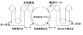
- Examples 1 to 3 are manufactured by the method according to the third embodiment shown in FIG. 4, and Examples 4 to 9 are manufactured by the method according to the second embodiment shown in FIG. Examples 10 to 16 were produced by the method according to Embodiment 1 shown in FIG. Comparative Examples 1 to 3 are manufactured by the conventional method shown in FIG.
- Electrolytic plating solution composition (Cu: 50 g / L, H 2 SO 4 : 50 g / L, Cl: 60 ppm) -Electroplating bath temperature: 45 ° C -Current density of electrolytic plating: 30 A / dm 2 Supporting copper foil transport tension: 0.05kg / mm (B) Foil handling method using drums ⁇ Anode: insoluble electrode ⁇ Cathode: surface of supporting copper foil supported on drum of 100 cm in diameter ⁇ Distance between electrodes (shown in Table 1) Electrolytic plating solution composition (Cu: 100 g / L, H 2 SO 4 : 80 g / L, Cl: 60 ppm -Electroplating bath temperature: 55 ° C -Current density of electrolytic plating: 30 A /
- Electrolytic plating solution composition (Cu: 10 g / L, H 2 SO 4 : 50 g / L) -Electroplating bath temperature: 40 ° C -Current density of electrolytic plating: 30 A / dm 2 Supporting copper foil transport tension: 0.05kg / mm (B) Foil handling method using drums ⁇ Anode: insoluble electrode ⁇ Cathode: surface of supporting copper foil supported on a 100 cm diameter drum ⁇ Distance between electrodes (shown in Table 1) Electrolytic plating solution composition (Cu: 20 g / L, H 2 SO 4 : 50 g / L) -Electroplating bath temperature: 40 ° C -Current density of electrolytic plating: 30 A / dm 2 Supporting copper foil transport tension: 0.05kg /
- Thickness accuracy (%) 3 ⁇ ⁇ 100 / average value
- the repeatability of this measurement method was 0.2%.
- the weighing machine used was HF-400 manufactured by A & D Co., Ltd., and the pressing machine used was HAP-12 manufactured by Noguchi Press Co., Ltd.
- the thickness accuracy by the weight-thickness method is 3% or less for the ultrathin copper layer, and the thickness accuracy by the four-probe method is 10% or less, and the thickness variation is good. Was suppressed.
- the thickness accuracy by the weight-thickness method is more than 3% for the ultrathin copper layer, and the thickness accuracy by the four-probe method is all more than 10%, and the thickness variation is large. It was.
Landscapes
- Chemical & Material Sciences (AREA)
- Engineering & Computer Science (AREA)
- Chemical Kinetics & Catalysis (AREA)
- Electrochemistry (AREA)
- Materials Engineering (AREA)
- Metallurgy (AREA)
- Organic Chemistry (AREA)
- Microelectronics & Electronic Packaging (AREA)
- Health & Medical Sciences (AREA)
- Toxicology (AREA)
- Electroplating Methods And Accessories (AREA)
- Parts Printed On Printed Circuit Boards (AREA)
- Laminated Bodies (AREA)
Abstract
Description
そこで、本発明は、支持銅箔上の極薄銅層の厚み精度を向上させた極薄銅箔を提供する課題とする。
本発明に用いることのできる支持銅箔は、典型的には圧延銅箔や電解銅箔の形態で提供される。一般的には、電解銅箔は硫酸銅めっき浴からチタンやステンレスのドラム上に銅を電解析出して製造され、圧延銅箔は圧延ロールによる塑性加工と熱処理を繰り返して製造される。銅箔の材料としてはタフピッチ銅や無酸素銅といった高純度の銅の他、例えばSn入り銅、Ag入り銅、Cr、Zr又はMg等を添加した銅合金、Ni及びSi等を添加したコルソン系銅合金のような銅合金も使用可能である。なお、本明細書において用語「銅箔」を単独で用いたときには銅合金箔も含むものとする。
支持銅箔上には剥離層を設ける。剥離層は、ニッケル、ニッケル-リン合金、ニッケル-コバルト合金、クロム等を用いて形成することができる。剥離層は、極薄銅層から支持銅箔を剥がすときに剥離する部分であるが、支持銅箔から銅成分が極薄銅層へと拡散していくのを防ぐバリア効果を持たせることもできる。
支持銅箔として電解銅箔を使用する場合には、ピンホールを減少させる観点から低粗度面に剥離層を設けることが好ましい。剥離層はめっき、スパッタリング、CVD、物理蒸着等の方法を用いて設けることができる。
剥離層の上には極薄銅層を設ける。極薄銅層は、硫酸銅、ピロリン酸銅、スルファミン酸銅、シアン化銅等の電解浴を利用した電気めっきにより形成することができ、一般的な電解銅箔で使用され、高電流密度での銅箔形成が可能であることから硫酸銅浴が好ましい。極薄銅層の厚みは特に制限はないが、一般的には支持銅箔よりも薄く、例えば12μm以下である。典型的には0.5~10μmであり、より典型的には1~5μmである。
極薄銅層の表面には、例えば絶縁基板との密着性を良好にすること等のために粗化処理を施すことで粗化粒子層を設けてもよい。粗化処理は、例えば、銅又は銅合金で粗化粒子を形成することにより行うことができる。粗化処理は微細なものであっても良い。粗化粒子層は、銅、ニッケル、コバルト及び亜鉛からなる群から選択されたいずれかの単体又はいずれか1種以上を含む合金からなる層であってもよい。また、粗化処理をした後、または粗化処理を行わずに、ニッケル、コバルト、銅、亜鉛の単体または合金で二次粒子や三次粒子及び/又は防錆層を形成し、さらにその表面にクロメート処理、シランカップリング処理などの処理を施してもよい。すなわち、粗化粒子層の表面に、防錆層、クロメート処理層及びシランカップリング処理層からなる群から選択された1種以上の層を形成してもよく、極薄銅層の表面に、防錆層、クロメート処理層及びシランカップリング処理層からなる群から選択された1種以上の層を形成してもよい。
極薄銅箔は、支持銅箔と、支持銅箔上に形成された剥離層と、剥離層の上に積層された極薄銅層とを備える。極薄銅箔自体の使用方法は当業者に周知であるが、例えば極薄銅層の表面を紙基材フェノール樹脂、紙基材エポキシ樹脂、合成繊維布基材エポキシ樹脂、ガラス布・紙複合基材エポキシ樹脂、ガラス布・ガラス不織布複合基材エポキシ樹脂及びガラス布基材エポキシ樹脂、ポリエステルフィルム、ポリイミドフィルム等の絶縁基板に貼り合わせて熱圧着後にキャリアを剥がし、絶縁基板に接着した極薄銅層を目的とする導体パターンにエッチングし、最終的にプリント配線板を製造することができる。本発明に係る極薄銅箔の場合、剥離箇所は主として剥離層と極薄銅層の界面である。
次に、本発明に係る極薄銅箔の製造方法を説明する。図2は、本発明の実施形態1に係る極薄銅箔の製造方法に係る運箔方式を示す模式図である。本発明の実施形態1に係る極薄銅箔の製造方法は、ロール・ツウ・ロール搬送方式により長さ方向に搬送される長尺状の支持銅箔の表面を処理することで、支持銅箔と、支持銅箔上に積層された剥離層と、剥離層上に積層された極薄銅層とを備えた極薄銅箔を製造する方法である。本発明の実施形態1に係る極薄銅箔の製造方法は、搬送ロールで搬送される支持銅箔をドラムで支持しながら、電解めっきにより支持銅箔表面に極薄銅層を形成する工程と、剥離層が形成された支持銅箔をドラムで支持しながら、電解めっきにより剥離層表面に極薄銅層を形成する工程と、支持銅箔をドラムで支持しながら、電解めっきにより極薄銅層表面に粗化粒子層を形成する工程とを含む。各工程ではドラムにて支持されている支持銅箔の処理面がカソードを兼ねており、このドラムと、ドラムに対向するように設けられたアノードとの間のめっき液中で各電解めっきが行われる。
ここで、重量厚み法による厚み精度の測定方法を説明する。まず、支持銅箔並びに極薄銅箔の重量を測定した後、極薄銅層を引き剥がし、再度支持銅箔の重量を測定し、前者と後者との差を極薄銅層の重量と定義する。測定対象となる極薄銅層片はプレス機で打ち抜いた3cm角シートとする。重量厚み精度を調査するため、各水準ともに、幅方向で等間隔に10点、長さ方向で6点(4cm間隔)、計60点の極薄銅層片の重量厚み測定値の平均値並びに標準偏差(σ)を求める。なお、重量厚み精度の算出式は次式とする。
厚み精度(%)=3σ×100/平均値
この測定方法の繰り返し精度は0.2%である。
ここで、四探針法による厚み精度の測定方法を説明する。まず、四探針にて厚み抵抗を測定することで支持銅箔と極薄銅箔との厚みを求めた後、極薄銅層を引き剥がし、再度支持銅箔の厚み抵抗による厚みを測定し、前者と後者との差を極薄銅層の厚みと定義する。厚み精度を調査するため、各水準ともに、幅方向で5mm間隔で測定をし、計280点の測定点の平均値並びに標準偏差(σ)を求める。なお、四探針による厚み精度の算出式は次式とする。
厚み精度(%)=3σ×100/平均値
この測定方法の繰り返し精度は1.0%である。
支持銅箔として、表1に記載の厚さの長尺の支持銅箔を準備した。実施例1、3、5~7、10、13、15、16、比較例1、2の銅箔は、電解銅箔(JX日鉱日石金属社製JTC)を用い、実施例2、4、8、9、11、12、14、比較例3の銅箔は、圧延銅箔(JX日鉱日石金属社製タフピッチ銅箔(JIS-H3100-C1100))を用いた。この銅箔のシャイニー面に対して、以下の条件でロール・トウ・ロール型の連続ラインで以下の条件で表1に記載の剥離層、極薄銅層及び粗化粒子層の各形成処理を行った。ここで、実施例1~3は上述の図4で示した実施形態3に係る方式で作製したものであり、実施例4~9は上述の図3で示した実施形態2に係る方式で作製したものであり、実施例10~16は上述の図2で示した実施形態1に係る方式で作製したものである。また、比較例1~3は、上述の図1で示した従来方式で作製したものである。
(A)九十九折による運箔方式
・アノード:不溶解性電極
・カソード:支持銅箔処理面
・極間距離(表1に示す)
・電解めっき液組成(NiSO4:100g/L)
・電解めっき液pH:6.7
・電解めっきの浴温:40℃
・電解めっきの電流密度:5A/dm2
・電解めっき時間:10秒
・支持銅箔搬送張力:0.05kg/mm
(B)ドラムによる運箔方式
・アノード:不溶解性電極
・カソード:直径100cmドラムに支持された支持銅箔表面
・極間距離(表1に示す)
・電解めっき液組成(NiSO4:100g/L)
・電解めっき液pH:6.7
・電解めっきの浴温:40℃
・電解めっきの電流密度:5A/dm2
・電解めっき時間:10秒
・支持銅箔搬送張力:0.05kg/mm
(A)九十九折による運箔方式
・アノード:不溶解性電極
・カソード:支持銅箔処理面
・極間距離(表1に示す)
・電解めっき液組成(Cu:50g/L、H2SO4:50g/L、Cl:60ppm)
・電解めっきの浴温:45℃
・電解めっきの電流密度:30A/dm2
・支持銅箔搬送張力:0.05kg/mm
(B)ドラムによる運箔方式
・アノード:不溶解性電極
・カソード:直径100cmドラムに支持された支持銅箔表面
・極間距離(表1に示す)
・電解めっき液組成(Cu:100g/L、H2SO4:80g/L、Cl:60ppm
・電解めっきの浴温:55℃
・電解めっきの電流密度:30A/dm2
・支持銅箔搬送張力:0.05kg/mm
(A)九十九折による運箔方式
・アノード:不溶解性電極
・カソード:支持銅箔処理面
・極間距離(表1に示す)
・電解めっき液組成(Cu:10g/L、H2SO4:50g/L)
・電解めっきの浴温:40℃
・電解めっきの電流密度:30A/dm2
・支持銅箔搬送張力:0.05kg/mm
(B)ドラムによる運箔方式
・アノード:不溶解性電極
・カソード:直径100cmドラムに支持された支持銅箔表面
・極間距離(表1に示す)
・電解めっき液組成(Cu:20g/L、H2SO4:50g/L)
・電解めっきの浴温:40℃
・電解めっきの電流密度:30A/dm2
・支持銅箔搬送張力:0.05kg/mm
上記のようにして得られた極薄銅箔について、以下の方法で厚み精度の評価を実施した。結果を表1に示す。
まず、支持銅箔並びに極薄銅箔の重量を測定した後、極薄銅層を引き剥がし、再度支持銅箔の重量を測定し、前者と後者との差を極薄銅層の重量と定義した。測定対象となる極薄銅層片はプレス機で打ち抜いた3cm角シートとした。重量厚み精度を調査するため、各水準ともに、幅方向で等間隔に10点、長さ方向で6点(4cm間隔)、計60点の極薄銅層片の重量厚み測定値の平均値並びに標準偏差(σ)を求めた。重量厚み精度の算出式は次式とした。
厚み精度(%)=3σ×100/平均値
この測定方法の繰り返し精度は0.2%であった。
また、重量計は、株式会社エー・アンド・デイ製HF-400を用い、プレス機は、野口プレス株式会社製HAP-12を用いた。
四探針にて厚み抵抗を測定することで支持銅箔と極薄銅箔との厚みを求めた後、極薄銅層を引き剥がし、再度支持銅箔の厚み抵抗による厚みを測定し、前者と後者との差を極薄銅層の厚みと定義した。厚み精度を調査するため、各水準ともに、幅方向で5mm間隔で計280点の測定点の平均値並びに標準偏差(σ)を求めた。四探針による厚み精度の算出式は次式とした。
厚み精度(%)=3σ×100/平均値
この測定方法の繰り返し精度は1.0%であった。
また、四探針は、OXFORD INSTRUMENTS社製CMI-700を用いた。

実施例1~16は、極薄銅層について、重量厚み法による厚み精度がいずれも3%以下であり、且つ、四探針法による厚み精度がいずれも10%以下であり、厚みバラツキが良好に抑制されていた。
比較例1~3は、極薄銅層について、重量厚み法による厚み精度がいずれも3%超であり、且つ、四探針法による厚み精度がいずれも10%超であり、厚みバラツキが大きかった。
Claims (12)
- 支持銅箔と、支持銅箔上に積層された剥離層と、剥離層上に積層された極薄銅層とを備えた極薄銅箔であって、
重量厚み法にて測定した前記極薄銅層の厚み精度が3.0%以下である極薄銅箔。 - 支持銅箔と、支持銅箔上に積層された剥離層と、剥離層上に積層された極薄銅層とを備えた極薄銅箔であって、
四探針法にて測定した前記極薄銅層の厚み精度が10.0%以下である極薄銅箔。 - 前記極薄銅層表面に粗化粒子層を有する請求項1又は2に記載の極薄銅箔。
- ロール・ツウ・ロール搬送方式により長さ方向に搬送される長尺状の支持銅箔の表面を処理することで、支持銅箔と、支持銅箔上に積層された剥離層と、剥離層上に積層された極薄銅層とを備えた極薄銅箔を製造する方法であり、
搬送ロールで搬送される支持銅箔の表面に剥離層を形成する工程と、
搬送ロールで搬送される前記剥離層が形成された支持銅箔をドラムで支持しながら、電解めっきにより前記剥離層表面に極薄銅層を形成する工程と、
を含む極薄銅箔の製造方法。 - 前記剥離層を形成する工程は、搬送ロールで搬送される前記支持銅箔をドラムで支持しながら、電解めっきにより前記支持銅箔表面に極薄銅層を形成することで行う請求項4に記載の極薄銅箔の製造方法。
- 搬送ロールで搬送される前記支持銅箔の極薄銅層表面に、粗化粒子層を形成する工程をさらに含む請求項4又は5に記載の極薄銅箔の製造方法。
- 前記粗化粒子層を形成する工程は、搬送ロールで搬送される前記支持銅箔をドラムで支持しながら、電解めっきにより前記極薄銅層表面に粗化粒子層を形成することで行う請求項6に記載の極薄銅箔の製造方法。
- 支持銅箔上に積層された剥離層上に積層されて、前記支持銅箔及び前記剥離層と共に極薄銅箔を構成するための、電解銅箔による極薄銅層であって、
重量厚み法にて測定した厚み精度が3.0%以下である極薄銅層。 - 支持銅箔上に積層された剥離層上に積層されて、前記支持銅箔及び前記剥離層と共に極薄銅箔を構成するための、電解銅箔による極薄銅層であって、
四探針法にて測定した厚み精度が10.0%以下である極薄銅層。 - 支持銅箔上に積層された剥離層上に積層されて、前記支持銅箔及び前記剥離層と共に極薄銅箔を構成するための、電解銅箔による極薄銅層であって、
表面に粗化粒子層を有する請求項8又は9に記載の極薄銅層。 - 請求項1~3のいずれかに記載の極薄銅箔を用いて製造されたプリント配線板。
- 請求項8~10のいずれかに記載の極薄銅層を用いたプリント配線板。
Priority Applications (8)
| Application Number | Priority Date | Filing Date | Title |
|---|---|---|---|
| KR1020137021154A KR20140017549A (ko) | 2012-07-06 | 2012-12-25 | 극박 동박 및 그 제조 방법, 그리고 극박 구리층 |
| CN201280069847.4A CN104114751A (zh) | 2012-07-06 | 2012-12-25 | 极薄铜箔及其制备方法以及极薄铜层 |
| KR1020137002706A KR101340828B1 (ko) | 2012-07-06 | 2012-12-25 | 극박 동박 및 그 제조 방법, 그리고 극박 구리층 |
| HK14112010.5A HK1198549A1 (en) | 2012-07-06 | 2012-12-25 | Ultrathin copper foil, method for producing same, and ultrathin copper layer |
| EP12880617.1A EP2871266A4 (en) | 2012-07-06 | 2012-12-25 | ULTRADÜNNE COPPER FILM, MANUFACTURING METHOD AND ULTRADÜNNE COPPER LAYER |
| US14/412,834 US9930776B2 (en) | 2012-07-06 | 2012-12-25 | Ultrathin copper foil and method of manufacturing the same, and ultrathin copper layer |
| KR1020177009194A KR20170039777A (ko) | 2012-07-06 | 2012-12-25 | 극박 동박 및 그 제조 방법, 그리고 극박 구리층 |
| PH12015500027A PH12015500027B1 (en) | 2012-07-06 | 2015-01-06 | Ultrathin copper foil, method of manufacturing the same, and ultrathin copper layer |
Applications Claiming Priority (2)
| Application Number | Priority Date | Filing Date | Title |
|---|---|---|---|
| JP2012152823A JP5175992B1 (ja) | 2012-07-06 | 2012-07-06 | 極薄銅箔及びその製造方法、並びに極薄銅層 |
| JP2012-152823 | 2012-07-06 |
Publications (1)
| Publication Number | Publication Date |
|---|---|
| WO2014006781A1 true WO2014006781A1 (ja) | 2014-01-09 |
Family
ID=48189391
Family Applications (1)
| Application Number | Title | Priority Date | Filing Date |
|---|---|---|---|
| PCT/JP2012/083531 Ceased WO2014006781A1 (ja) | 2012-07-06 | 2012-12-25 | 極薄銅箔及びその製造方法、並びに極薄銅層 |
Country Status (10)
| Country | Link |
|---|---|
| US (1) | US9930776B2 (ja) |
| EP (1) | EP2871266A4 (ja) |
| JP (1) | JP5175992B1 (ja) |
| KR (3) | KR101340828B1 (ja) |
| CN (1) | CN104114751A (ja) |
| HK (1) | HK1198549A1 (ja) |
| MY (1) | MY170525A (ja) |
| PH (1) | PH12015500027B1 (ja) |
| TW (1) | TWI435804B (ja) |
| WO (1) | WO2014006781A1 (ja) |
Families Citing this family (15)
| Publication number | Priority date | Publication date | Assignee | Title |
|---|---|---|---|---|
| JP6396641B2 (ja) * | 2013-04-03 | 2018-09-26 | Jx金属株式会社 | キャリア付銅箔及びその製造方法、極薄銅層、銅張積層板の製造方法、並びにプリント配線板の製造方法 |
| JP6246486B2 (ja) * | 2013-04-03 | 2017-12-13 | Jx金属株式会社 | キャリア付銅箔及びその製造方法、銅張積層板の製造方法及びプリント配線板の製造方法 |
| JP6134569B2 (ja) * | 2013-04-03 | 2017-05-24 | Jx金属株式会社 | キャリア付銅箔、キャリア付銅箔の製造方法、銅張積層板の製造方法及びプリント配線板の製造方法 |
| JP6254357B2 (ja) * | 2013-04-03 | 2017-12-27 | Jx金属株式会社 | キャリア付銅箔 |
| JP6158573B2 (ja) * | 2013-04-03 | 2017-07-05 | Jx金属株式会社 | キャリア付銅箔、銅張積層板の製造方法及びプリント配線板の製造方法 |
| JP2015133342A (ja) * | 2014-01-09 | 2015-07-23 | 京セラサーキットソリューションズ株式会社 | 配線基板の製造方法 |
| KR102781999B1 (ko) * | 2016-10-12 | 2025-03-14 | 에스케이넥실리스 주식회사 | 핸들링이 용이한 전해동박, 그것을 포함하는 전극, 그것을 포함하는 이차전지, 및 그것의 제조방법 |
| CN109518131A (zh) * | 2018-12-25 | 2019-03-26 | 胡旭日 | 一种带载体的极薄铜箔、极薄铜箔生产方法及装置 |
| CN111640915B (zh) | 2019-03-01 | 2024-12-31 | 麻省固能控股有限公司 | 负极、包括其的二次电池以及制造负极的方法 |
| US11444277B2 (en) | 2019-03-01 | 2022-09-13 | Ses Holdings Pte. Ltd. | Anodes, secondary batteries including the same, and methods of making anodes |
| CN110027982B (zh) * | 2019-03-24 | 2020-08-21 | 荆门市亿美工业设计有限公司 | 一种防锈铜箔卷吊具 |
| KR102323914B1 (ko) * | 2021-05-17 | 2021-11-08 | 에스케이넥실리스 주식회사 | 동박 제조장치 |
| KR102323908B1 (ko) * | 2021-06-01 | 2021-11-08 | 에스케이넥실리스 주식회사 | 동박 제조장치 |
| KR102517417B1 (ko) * | 2021-07-09 | 2023-04-03 | 주식회사 다이브 | 반도체용 동박의 제조방법 및 이를 이용한 반도체용 동박 |
| CN118685827B (zh) * | 2024-08-23 | 2024-12-13 | 安徽华威铜箔科技有限公司 | 一种一体式载体铜箔生产设备 |
Citations (8)
| Publication number | Priority date | Publication date | Assignee | Title |
|---|---|---|---|---|
| JPS6187889A (ja) * | 1984-10-04 | 1986-05-06 | Kawasaki Steel Corp | 合金薄帯の製造方法 |
| JPH04341596A (ja) * | 1991-05-17 | 1992-11-27 | Toagosei Chem Ind Co Ltd | 極薄銅張積層板の連続製造装置 |
| JPH08209396A (ja) * | 1994-12-30 | 1996-08-13 | Ishifuku Metal Ind Co Ltd | 電解用複合電極 |
| JP2000309898A (ja) | 1999-04-23 | 2000-11-07 | Mitsui Mining & Smelting Co Ltd | キャリア箔付電解銅箔及びその電解銅箔の製造方法並びにその電解銅箔を使用した銅張積層板 |
| JP2003033994A (ja) * | 2001-07-24 | 2003-02-04 | Toyo Metallizing Co Ltd | 金属化フィルム及び金属箔 |
| JP2004035985A (ja) * | 2002-07-08 | 2004-02-05 | Kawasaki Heavy Ind Ltd | 金属箔の表面メッキ装置 |
| JP2004131821A (ja) * | 2002-10-11 | 2004-04-30 | Kawasaki Heavy Ind Ltd | 表面処理設備用ロール |
| WO2012046804A1 (ja) * | 2010-10-06 | 2012-04-12 | 古河電気工業株式会社 | 銅箔及びその製造方法、キャリア付き銅箔及びその製造方法、プリント配線板、多層プリント配線板 |
Family Cites Families (16)
| Publication number | Priority date | Publication date | Assignee | Title |
|---|---|---|---|---|
| US4921590A (en) * | 1989-03-27 | 1990-05-01 | Yates Industries, Inc. | Production of metal foil having improved weight distribution across the width of the foil |
| DE69117155T2 (de) * | 1990-12-19 | 1996-09-05 | Nikko Gould Foil Co | Verfahren und Vorrichtung zur elektrolytischen Erzeugung von Kupferfolien |
| US5326455A (en) * | 1990-12-19 | 1994-07-05 | Nikko Gould Foil Co., Ltd. | Method of producing electrolytic copper foil and apparatus for producing same |
| US5069762A (en) | 1991-01-18 | 1991-12-03 | Usx Corporation | Appartaus for improved current transfer in radial cell electroplating |
| US5164059A (en) | 1991-03-11 | 1992-11-17 | Newcor, Inc. | Electroplating apparatus with improved current collector |
| US6270889B1 (en) * | 1998-01-19 | 2001-08-07 | Mitsui Mining & Smelting Co., Ltd. | Making and using an ultra-thin copper foil |
| JP3370624B2 (ja) * | 1999-08-24 | 2003-01-27 | 三井金属鉱業株式会社 | キャリア箔付電解銅箔及びその電解銅箔を使用した銅張積層板 |
| US6447929B1 (en) * | 2000-08-29 | 2002-09-10 | Gould Electronics Inc. | Thin copper on usable carrier and method of forming same |
| JP4426127B2 (ja) * | 2001-03-29 | 2010-03-03 | 三井金属鉱業株式会社 | 金属箔電解製造装置 |
| JP2005008973A (ja) | 2003-06-20 | 2005-01-13 | Hitachi Cable Ltd | 銅箔の表面粗化方法 |
| TW200609109A (en) | 2004-08-02 | 2006-03-16 | Nippon Denkai Ltd | Composite copper foil and method for production thereof |
| JP4927503B2 (ja) * | 2005-12-15 | 2012-05-09 | 古河電気工業株式会社 | キャリア付き極薄銅箔及びプリント配線基板 |
| JP4712759B2 (ja) * | 2006-06-07 | 2011-06-29 | 古河電気工業株式会社 | 表面処理電解銅箔及びその製造方法、並びに回路基板 |
| CN102203326A (zh) | 2008-09-05 | 2011-09-28 | 古河电气工业株式会社 | 带有载体的极薄铜箔以及贴铜层压板或印刷线路基板 |
| EP2431107A1 (de) * | 2010-09-16 | 2012-03-21 | Siemens VAI Metals Technologies GmbH | Verfahren zum Transfer eines Metallbundes |
| JP5723971B2 (ja) | 2011-03-25 | 2015-05-27 | Jx日鉱日石金属株式会社 | 複合銅箔及びその製造方法 |
-
2012
- 2012-07-06 JP JP2012152823A patent/JP5175992B1/ja not_active Expired - Fee Related
- 2012-12-25 EP EP12880617.1A patent/EP2871266A4/en not_active Withdrawn
- 2012-12-25 MY MYPI2014704053A patent/MY170525A/en unknown
- 2012-12-25 KR KR1020137002706A patent/KR101340828B1/ko not_active Expired - Fee Related
- 2012-12-25 US US14/412,834 patent/US9930776B2/en active Active
- 2012-12-25 WO PCT/JP2012/083531 patent/WO2014006781A1/ja not_active Ceased
- 2012-12-25 CN CN201280069847.4A patent/CN104114751A/zh active Pending
- 2012-12-25 KR KR1020177009194A patent/KR20170039777A/ko not_active Ceased
- 2012-12-25 HK HK14112010.5A patent/HK1198549A1/xx unknown
- 2012-12-25 KR KR1020137021154A patent/KR20140017549A/ko not_active Ceased
- 2012-12-27 TW TW101150319A patent/TWI435804B/zh not_active IP Right Cessation
-
2015
- 2015-01-06 PH PH12015500027A patent/PH12015500027B1/en unknown
Patent Citations (8)
| Publication number | Priority date | Publication date | Assignee | Title |
|---|---|---|---|---|
| JPS6187889A (ja) * | 1984-10-04 | 1986-05-06 | Kawasaki Steel Corp | 合金薄帯の製造方法 |
| JPH04341596A (ja) * | 1991-05-17 | 1992-11-27 | Toagosei Chem Ind Co Ltd | 極薄銅張積層板の連続製造装置 |
| JPH08209396A (ja) * | 1994-12-30 | 1996-08-13 | Ishifuku Metal Ind Co Ltd | 電解用複合電極 |
| JP2000309898A (ja) | 1999-04-23 | 2000-11-07 | Mitsui Mining & Smelting Co Ltd | キャリア箔付電解銅箔及びその電解銅箔の製造方法並びにその電解銅箔を使用した銅張積層板 |
| JP2003033994A (ja) * | 2001-07-24 | 2003-02-04 | Toyo Metallizing Co Ltd | 金属化フィルム及び金属箔 |
| JP2004035985A (ja) * | 2002-07-08 | 2004-02-05 | Kawasaki Heavy Ind Ltd | 金属箔の表面メッキ装置 |
| JP2004131821A (ja) * | 2002-10-11 | 2004-04-30 | Kawasaki Heavy Ind Ltd | 表面処理設備用ロール |
| WO2012046804A1 (ja) * | 2010-10-06 | 2012-04-12 | 古河電気工業株式会社 | 銅箔及びその製造方法、キャリア付き銅箔及びその製造方法、プリント配線板、多層プリント配線板 |
Also Published As
| Publication number | Publication date |
|---|---|
| MY170525A (en) | 2019-08-09 |
| US9930776B2 (en) | 2018-03-27 |
| JP2014015650A (ja) | 2014-01-30 |
| HK1198549A1 (en) | 2015-05-15 |
| US20150195909A1 (en) | 2015-07-09 |
| PH12015500027A1 (en) | 2015-02-23 |
| CN104114751A (zh) | 2014-10-22 |
| KR20170039777A (ko) | 2017-04-11 |
| EP2871266A4 (en) | 2016-03-30 |
| KR101340828B1 (ko) | 2013-12-11 |
| EP2871266A1 (en) | 2015-05-13 |
| TWI435804B (zh) | 2014-05-01 |
| JP5175992B1 (ja) | 2013-04-03 |
| KR20140017549A (ko) | 2014-02-11 |
| TW201331024A (zh) | 2013-08-01 |
| PH12015500027B1 (en) | 2017-10-06 |
Similar Documents
| Publication | Publication Date | Title |
|---|---|---|
| JP5175992B1 (ja) | 極薄銅箔及びその製造方法、並びに極薄銅層 | |
| JP5710737B1 (ja) | 表面処理銅箔、積層板、プリント配線板、プリント回路板及び電子機器 | |
| JP5859155B1 (ja) | 複合金属箔及びその製造方法並びにプリント配線板 | |
| KR101669745B1 (ko) | 2층 플렉시블 배선용 기판 및 플렉시블 배선판 및 이들의 제조 방법 | |
| CN104080951B (zh) | 印刷电路板用铜箔和使用其的层叠体、印刷电路板以及电子部件 | |
| JP6134569B2 (ja) | キャリア付銅箔、キャリア付銅箔の製造方法、銅張積層板の製造方法及びプリント配線板の製造方法 | |
| JP5156873B1 (ja) | キャリア付銅箔 | |
| JP5347074B1 (ja) | 極薄銅箔及びその製造方法、極薄銅層、並びにプリント配線板 | |
| JP2011037214A (ja) | 金属被覆ポリイミドフィルムとその製造方法 | |
| KR20070033005A (ko) | 복합 구리박 및 그 제조방법 | |
| JP6158573B2 (ja) | キャリア付銅箔、銅張積層板の製造方法及びプリント配線板の製造方法 | |
| JP2015105440A (ja) | 表面処理銅箔、積層板、プリント配線板、プリント回路板及び電子機器 | |
| JP6592029B2 (ja) | キャリア付銅箔及びその製造方法、極薄銅層、銅張積層板の製造方法、並びにプリント配線板の製造方法 | |
| JP6396641B2 (ja) | キャリア付銅箔及びその製造方法、極薄銅層、銅張積層板の製造方法、並びにプリント配線板の製造方法 | |
| JP6054523B2 (ja) | キャリア付銅箔、キャリア付銅箔の製造方法、キャリア付銅箔を用いて得られる銅張積層板及びプリント配線板の製造方法 | |
| JP6592028B2 (ja) | キャリア付銅箔及びその製造方法、極薄銅層、銅張積層板の製造方法、並びにプリント配線板の製造方法 | |
| JP2012064769A (ja) | プリント配線板用銅箔 | |
| JP6360659B2 (ja) | キャリア付き銅箔、当該キャリア付き銅箔を用いてプリント配線板を製造する方法、当該キャリア付き銅箔を用いて銅張積層板を製造する方法、及びプリント配線板の製造方法 | |
| JP6246486B2 (ja) | キャリア付銅箔及びその製造方法、銅張積層板の製造方法及びプリント配線板の製造方法 | |
| JP6254357B2 (ja) | キャリア付銅箔 | |
| KR20160098593A (ko) | 연성 구리박막 적층필름의 제조방법 및 그로부터 제조되는 세미 애디티브 공정용 연성 구리박막 적층필름 |
Legal Events
| Date | Code | Title | Description |
|---|---|---|---|
| ENP | Entry into the national phase |
Ref document number: 20137002706 Country of ref document: KR Kind code of ref document: A |
|
| 121 | Ep: the epo has been informed by wipo that ep was designated in this application |
Ref document number: 12880617 Country of ref document: EP Kind code of ref document: A1 |
|
| WWE | Wipo information: entry into national phase |
Ref document number: 14412834 Country of ref document: US |
|
| WWE | Wipo information: entry into national phase |
Ref document number: 12015500027 Country of ref document: PH |
|
| NENP | Non-entry into the national phase |
Ref country code: DE |
|
| WWE | Wipo information: entry into national phase |
Ref document number: 2012880617 Country of ref document: EP |