WO2014006829A1 - 空気入りタイヤ - Google Patents
空気入りタイヤ Download PDFInfo
- Publication number
- WO2014006829A1 WO2014006829A1 PCT/JP2013/003795 JP2013003795W WO2014006829A1 WO 2014006829 A1 WO2014006829 A1 WO 2014006829A1 JP 2013003795 W JP2013003795 W JP 2013003795W WO 2014006829 A1 WO2014006829 A1 WO 2014006829A1
- Authority
- WO
- WIPO (PCT)
- Prior art keywords
- groove
- tire
- sub
- pneumatic tire
- block
- Prior art date
- Legal status (The legal status is an assumption and is not a legal conclusion. Google has not performed a legal analysis and makes no representation as to the accuracy of the status listed.)
- Ceased
Links
Images


Classifications
-
- B—PERFORMING OPERATIONS; TRANSPORTING
- B60—VEHICLES IN GENERAL
- B60C—VEHICLE TYRES; TYRE INFLATION; TYRE CHANGING; CONNECTING VALVES TO INFLATABLE ELASTIC BODIES IN GENERAL; DEVICES OR ARRANGEMENTS RELATED TO TYRES
- B60C11/00—Tyre tread bands; Tread patterns; Anti-skid inserts
- B60C11/03—Tread patterns
- B60C11/11—Tread patterns in which the raised area of the pattern consists only of isolated elements, e.g. blocks
-
- B—PERFORMING OPERATIONS; TRANSPORTING
- B60—VEHICLES IN GENERAL
- B60C—VEHICLE TYRES; TYRE INFLATION; TYRE CHANGING; CONNECTING VALVES TO INFLATABLE ELASTIC BODIES IN GENERAL; DEVICES OR ARRANGEMENTS RELATED TO TYRES
- B60C11/00—Tyre tread bands; Tread patterns; Anti-skid inserts
- B60C11/01—Shape of the shoulders between tread and sidewall, e.g. rounded, stepped or cantilevered
-
- B—PERFORMING OPERATIONS; TRANSPORTING
- B60—VEHICLES IN GENERAL
- B60C—VEHICLE TYRES; TYRE INFLATION; TYRE CHANGING; CONNECTING VALVES TO INFLATABLE ELASTIC BODIES IN GENERAL; DEVICES OR ARRANGEMENTS RELATED TO TYRES
- B60C11/00—Tyre tread bands; Tread patterns; Anti-skid inserts
- B60C11/03—Tread patterns
- B60C11/0306—Patterns comprising block rows or discontinuous ribs
-
- B—PERFORMING OPERATIONS; TRANSPORTING
- B60—VEHICLES IN GENERAL
- B60C—VEHICLE TYRES; TYRE INFLATION; TYRE CHANGING; CONNECTING VALVES TO INFLATABLE ELASTIC BODIES IN GENERAL; DEVICES OR ARRANGEMENTS RELATED TO TYRES
- B60C11/00—Tyre tread bands; Tread patterns; Anti-skid inserts
- B60C11/03—Tread patterns
- B60C11/12—Tread patterns characterised by the use of narrow slits or incisions, e.g. sipes
- B60C11/1272—Width of the sipe
-
- B—PERFORMING OPERATIONS; TRANSPORTING
- B60—VEHICLES IN GENERAL
- B60C—VEHICLE TYRES; TYRE INFLATION; TYRE CHANGING; CONNECTING VALVES TO INFLATABLE ELASTIC BODIES IN GENERAL; DEVICES OR ARRANGEMENTS RELATED TO TYRES
- B60C11/00—Tyre tread bands; Tread patterns; Anti-skid inserts
- B60C11/03—Tread patterns
- B60C11/12—Tread patterns characterised by the use of narrow slits or incisions, e.g. sipes
-
- B—PERFORMING OPERATIONS; TRANSPORTING
- B60—VEHICLES IN GENERAL
- B60C—VEHICLE TYRES; TYRE INFLATION; TYRE CHANGING; CONNECTING VALVES TO INFLATABLE ELASTIC BODIES IN GENERAL; DEVICES OR ARRANGEMENTS RELATED TO TYRES
- B60C11/00—Tyre tread bands; Tread patterns; Anti-skid inserts
- B60C11/03—Tread patterns
- B60C2011/0337—Tread patterns characterised by particular design features of the pattern
- B60C2011/0339—Grooves
- B60C2011/0341—Circumferential grooves
- B60C2011/0348—Narrow grooves, i.e. having a width of less than 4 mm
-
- B—PERFORMING OPERATIONS; TRANSPORTING
- B60—VEHICLES IN GENERAL
- B60C—VEHICLE TYRES; TYRE INFLATION; TYRE CHANGING; CONNECTING VALVES TO INFLATABLE ELASTIC BODIES IN GENERAL; DEVICES OR ARRANGEMENTS RELATED TO TYRES
- B60C11/00—Tyre tread bands; Tread patterns; Anti-skid inserts
- B60C11/03—Tread patterns
- B60C2011/0337—Tread patterns characterised by particular design features of the pattern
- B60C2011/0339—Grooves
- B60C2011/0341—Circumferential grooves
- B60C2011/0353—Circumferential grooves characterised by width
-
- B—PERFORMING OPERATIONS; TRANSPORTING
- B60—VEHICLES IN GENERAL
- B60C—VEHICLE TYRES; TYRE INFLATION; TYRE CHANGING; CONNECTING VALVES TO INFLATABLE ELASTIC BODIES IN GENERAL; DEVICES OR ARRANGEMENTS RELATED TO TYRES
- B60C11/00—Tyre tread bands; Tread patterns; Anti-skid inserts
- B60C11/03—Tread patterns
- B60C2011/0337—Tread patterns characterised by particular design features of the pattern
- B60C2011/0339—Grooves
- B60C2011/0358—Lateral grooves, i.e. having an angle of 45 to 90 degees to the equatorial plane
- B60C2011/036—Narrow grooves, i.e. having a width of less than 3 mm
-
- B—PERFORMING OPERATIONS; TRANSPORTING
- B60—VEHICLES IN GENERAL
- B60C—VEHICLE TYRES; TYRE INFLATION; TYRE CHANGING; CONNECTING VALVES TO INFLATABLE ELASTIC BODIES IN GENERAL; DEVICES OR ARRANGEMENTS RELATED TO TYRES
- B60C11/00—Tyre tread bands; Tread patterns; Anti-skid inserts
- B60C11/03—Tread patterns
- B60C2011/0337—Tread patterns characterised by particular design features of the pattern
- B60C2011/0339—Grooves
- B60C2011/0358—Lateral grooves, i.e. having an angle of 45 to 90 degees to the equatorial plane
- B60C2011/0365—Lateral grooves, i.e. having an angle of 45 to 90 degees to the equatorial plane characterised by width
-
- B—PERFORMING OPERATIONS; TRANSPORTING
- B60—VEHICLES IN GENERAL
- B60C—VEHICLE TYRES; TYRE INFLATION; TYRE CHANGING; CONNECTING VALVES TO INFLATABLE ELASTIC BODIES IN GENERAL; DEVICES OR ARRANGEMENTS RELATED TO TYRES
- B60C11/00—Tyre tread bands; Tread patterns; Anti-skid inserts
- B60C11/03—Tread patterns
- B60C2011/0337—Tread patterns characterised by particular design features of the pattern
- B60C2011/0339—Grooves
- B60C2011/0358—Lateral grooves, i.e. having an angle of 45 to 90 degees to the equatorial plane
- B60C2011/0372—Lateral grooves, i.e. having an angle of 45 to 90 degees to the equatorial plane with particular inclination angles
-
- B—PERFORMING OPERATIONS; TRANSPORTING
- B60—VEHICLES IN GENERAL
- B60C—VEHICLE TYRES; TYRE INFLATION; TYRE CHANGING; CONNECTING VALVES TO INFLATABLE ELASTIC BODIES IN GENERAL; DEVICES OR ARRANGEMENTS RELATED TO TYRES
- B60C11/00—Tyre tread bands; Tread patterns; Anti-skid inserts
- B60C11/03—Tread patterns
- B60C11/12—Tread patterns characterised by the use of narrow slits or incisions, e.g. sipes
- B60C11/1204—Tread patterns characterised by the use of narrow slits or incisions, e.g. sipes with special shape of the sipe
- B60C2011/1213—Tread patterns characterised by the use of narrow slits or incisions, e.g. sipes with special shape of the sipe sinusoidal or zigzag at the tread surface
Definitions
- the present invention relates to a pneumatic tire in which a large number of blocks are defined by grooves in a tread portion.
- the grounding area cannot be secured due to the falling of the block at the time of grounding and the grounding property is deteriorated, and the braking performance, traction performance, cornering on the road surface on ice.
- Performance (hereinafter referred to as performance on ice) was not sufficiently obtained. Further, if the rigidity is increased by increasing the size of each block to improve the ground contact property, the drainage property is insufficient. Therefore, it is difficult to improve the performance on ice without impairing the drainage property.
- an object of the present invention is to provide a pneumatic tire having an improved performance on ice by securing a ground contact area without impairing drainage by arranging an appropriate block pattern.
- the present invention has been made to solve the above problems, and the pneumatic tire of the present invention partitions a plurality of land portions in the tread portion by at least one circumferential main groove extending in the tire circumferential direction.
- the shoulder land portion located on the outermost side in the tire width direction of the land portion is formed with a plurality of narrow grooves having a groove width smaller than the circumferential main groove, and at least other than the vicinity of the circumferential main groove.
- a plurality of blocks are defined by at least one secondary groove whose groove width increases toward the outer side in the tire width direction, and the area of the tread surface of the block is in the range of 100 to 200 mm 2. To do.
- extending in the tire circumferential direction means extending in the tire circumferential direction, continuously extending in a zigzag shape toward the tire circumferential direction, or continuous while curving in the tire circumferential direction. It is also included when it extends.
- the groove width of the sub-grooves is set appropriately, in particular in the tire width direction. Since the ground contact area of the block can be ensured in this area, the performance on ice can be improved. In addition, since the area of the tread surface of the block is in the range of 100 to 200 mm 2 , the rigidity of each block is secured, and the effect of removing the water film between the tread surface of the block and the road surface is enhanced. The performance can be further improved.
- the sub-groove is open to the circumferential main groove and the tread grounding end, and according to this, between the circumferential main groove and the sub-groove. Therefore, it is possible to move the water and to drain through the sub-groove, so that the drainage is improved.
- the “tread grounding end” means the outermost position in the tire width direction of the surface where the tire surface contacts the ground in a state where the tire is assembled to the regular rim, the regular internal pressure is filled, and the regular load is applied.
- Regular rim refers to the standard rim specified in the following standards according to the tire size
- Regular internal pressure refers to the maximum single wheel at the applicable size described in the following standards. Air pressure corresponding to the load capacity is referred to
- normal load refers to the maximum load (maximum load capacity) of a single wheel in the applicable size of the following standard.
- the standard is an industrial standard that is effective in the area where tires are produced or used. For example, in Japan, the “JATMA YEAR BOOK” of the “Japan Automobile Tire Association” and in the United States “THE TIRE AND RIM ASSOCIATION INC” "YEAR BOOK” in Europe, and “STANDARD MANUAL” in "The European Tire and Rim Technical Organization” in Europe.
- the minimum groove width of the sub-groove is preferably equal to or less than the groove width of the narrow groove, and according to this, the ground contact area is more reliably increased, The performance on ice can be improved.
- the sub-groove has an inclined portion whose extending direction is inclined with respect to the tire width direction, and the inclined portion is directed from the inner side to the outer side in the tire width direction.
- the direction of the tire circumferential direction inclined with respect to the tire width direction is preferably the same on both sides with the tire equatorial plane as a boundary, and according to this, the drainage performance when the tire rotates in a predetermined direction is improved. Can be improved.
- each of the narrow groove and the sub-groove has an inclined portion that is inclined with respect to a tire circumferential direction and a tire width direction, and at least a part of the shoulder land portion.
- the slanted portion of the narrow groove and the slanted portion of the sub-groove intersect each other and are arranged in a lattice shape, and the tread surface shape of the block is a square shape, a pentagonal shape, a hexagonal shape, a heptagonal shape, or an octagonal shape, respectively. According to this, the drainage around the block is enhanced, and the polygonal block shape can be used to exert an edge effect in multiple directions, thereby further improving the performance on ice.
- an enlarged groove portion having a large groove width at an intersection portion where the narrow grooves intersect and an intersection portion where the narrow grooves and the sub-groove intersect According to the above, drainage can be improved, and on snowy road surfaces, snow column shearing force can be increased to improve snow performance.
- a sipe is formed on the tread surface of the block. According to this, the water film removing effect is enhanced and the edge effect is enhanced to improve the performance on ice. Can be made.
- sipe refers to a thin notch cut into the inside from the surface of the block, which can be closed when grounded.
- the groove width of the narrow groove is preferably in the range of 0.5 to 3.0 mm. According to this, the drainage property and the block rigidity are ensured. It can improve the ground contact and improve the performance on ice.
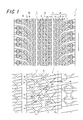
- FIG. 1 is a partial development view showing a tread pattern of a pneumatic tire (hereinafter referred to as “tire”) according to an embodiment of the present invention.
- tire a pneumatic tire
- the pneumatic tire in this embodiment is a tread part straddling between a pair of bead part, a pair of sidewall part connected to the tire radial direction outer side of a bead part, and a sidewall part according to usual.
- bead cores embedded in the bead part a carcass extending in a toroid shape extending over these parts, and a belt is disposed on the outer side in the tire radial direction of the crown part of the carcass.
- two circumferential main grooves 3 extending linearly along the tire circumferential direction are disposed in the tread portion of the tire 1, and one central land portion 5 a and two shoulders are disposed.
- the land portion 5b is partitioned.
- a large number of blocks 11 are defined by narrow grooves 7a, 7b and sub-grooves 9 in each shoulder land portion 5b.
- the groove width w0 of the narrow grooves 7a, 7b is smaller than the groove width w1 of the circumferential main groove, and the auxiliary groove 9 has a groove width that increases from the inner side to the outer side in the tire width direction.
- the sub-groove 9 is inclined to one side in the tire circumferential direction with respect to the tire width direction, and the narrow groove 7a extending incline in the same direction as the sub-groove 9 between the sub-grooves 9 adjacent in the tire circumferential direction. Is arranged.
- a narrow groove 7b inclined to the opposite side to the sub-groove 9 with respect to the tire width direction intersects the sub-groove 9 and the narrow groove 7a, and a plurality of these sub-grooves 9, the narrow grooves 7a, and the narrow grooves 7b are formed.
- a grid-like groove is formed.
- An enlarged groove part 13 having an enlarged groove width is formed at the intersection of the fine groove 7a and the sub groove 9 and the fine groove 7b.
- the blocks 11 defined by these grooves are arranged in a zigzag pattern along the tire circumferential direction, and the shape of the block 11 is a polygon such as an octagon obtained by cutting square corners.
- the sub-groove 9 opens to the circumferential main groove 3 and the tread grounding end TE, and a main groove opening 15 having a large groove width is formed in the opening to the circumferential main groove 3.
- the minor groove 9 has the smallest groove width in the vicinity of the main groove opening 15, and the smallest groove width w2 of the minor groove 9 is equal to or smaller than the groove width w0 of the narrow grooves 7a and 7b. That is, the groove width of the sub-groove 9 increases toward the outer side in the tire width direction at least in the vicinity of the circumferential main groove 3, that is, in a portion other than the main groove opening 15.
- the groove width w2 is equal to the groove width w0 of the narrow grooves 7a and 7b.
- the groove width w2 may be smaller than the groove width w0 of the narrow grooves 7a and 7b.
- the width of the main groove opening 15 is larger than w2, but may be equal to or less than w2.
- the groove width of the sub-groove 9 changes from the minimum groove width w2 toward the outer side in the tire width direction in steps of w3, w4, and w5. It may have changed.
- it is preferable that the groove width of the sub-groove 9 is changed in a stepwise manner. According to this, the edge region is increased, and the on-ice traction performance and the on-ice brake performance can be more reliably improved.
- the central land portion 5a has a plurality of narrow grooves 8 inclined in opposite directions and arranged in a lattice pattern, and a large number of blocks 12a and 12b are defined.
- the block 12a adjacent to the circumferential main groove 3 has a hexagonal shape, and the other blocks 12b have an octagonal shape.
- the circumferential main groove 3, the narrow grooves 7a and 7b, and the auxiliary groove 9 can ensure drainage, improve the ground contact of the block, and improve the performance on ice. Moreover, high drainage can be exhibited because the groove width of the sub-groove 9 increases toward the outer side in the tire width direction. Moreover, since the groove width of the sub-groove 9 on the inner side in the tire width direction is small, a ground contact area of the land portion can be secured and the performance on ice is improved.
- the sub-groove 9 is open to the circumferential main groove 3 and the tread grounding end TE, water movement between the circumferential main groove 3, the sub-groove 9, and the narrow grooves 7a and 7b is made free. In addition, since the water can be drained to the outside of the tread ground end TE, the drainage performance is further improved. Furthermore, since the minimum groove width of the sub-groove 9 is equal to or smaller than the groove widths of the narrow grooves 7a and 7b, the rigidity of the block is further secured, the grounding property of the block is improved, and the performance on ice is improved.
- the shoulder land portions 5b on both sides of the tire equatorial plane have a line-symmetric pattern shifted in the tire circumferential direction with the tire equatorial plane as a boundary, that is, all the auxiliary grooves 9 are directed from the inner side to the outer side in the tire width direction.
- the tire has a configuration that is inclined to the same side in the tire circumferential direction with respect to the tire width direction.
- the area of the tread of one single block 11, can be in the range of 100 ⁇ 200 mm 2, according to this, securing the rigidity of one single block
- the area of the tread surface of the blocks 12a and 12b is preferably in the range of 100 to 200 mm 2 in order to ensure drainage and block rigidity.
- the shape of the block 11 defined by the narrow grooves 7a and 7b and the sub-grooves 9 arranged in a lattice shape is a shape obtained by cutting a square corner portion,
- the octagonal block 11a, the pentagonal block 11b, the hexagonal block 11c, and the heptagonal block 11d can exhibit an edge effect against multidirectional forces, and Since the corners of the quadrangular shape are easily peeled by contact with the road surface, by cutting this part and making it chamfered, the effect of increasing the rigidity of each block and suppressing uneven wear is obtained. You can also.
- the narrow grooves 7a and 7b and the sub-grooves 9 are arranged in the tire circumferential direction by arranging the blocks so that one of the diagonal lines when each block 11 is regarded as a square extends in the tire circumferential direction. Further, the drainage in the tire circumferential direction is improved as compared with the grooves extending in parallel to the tire width direction.
- an enlarged groove portion 13 having an increased groove width is formed at the intersection of the narrow grooves 7a and 7b and the sub-groove 9 arranged in a lattice shape. That is, the block 11 adjacent to the groove enlarged portion 13 has a shape in which a square corner is chamfered.
- the distance between the blocks adjacent to each other in the tire circumferential direction and the tire width direction across the enlarged groove portion 13 is larger than when the narrow grooves 7a and 7b intersect with each other while the groove width is constant.
- At least one sipe 17 extending in a zigzag shape in the tire width direction is formed on the tread surface of each block 11 in this case, and an edge formed by the sipe 17 is formed.
- the effect can effectively improve the performance on ice.
- the extending direction of the sipe 17 can be set according to the performance to be emphasized. For example, when importance is attached to traction and braking performance, it is effective to arrange the tires along the tire width direction, and when the cornering performance is important, it is effective to incline with respect to the tire width direction.
- the groove width w0 of the narrow grooves 7a and 7b is preferably in the range of 0.5 to 3.0 mm. According to this, the drainage property and the water film removal performance are ensured, and the block rigidity is secured and the grounding property of the block is ensured. Can be improved and the performance on ice can be improved. If the groove width w0 of the narrow grooves 7a and 7b is less than 0.5 mm, there is a possibility that sufficient drainage performance may not be obtained, and there is a possibility that the effect of removing the water film is reduced and the grounding performance cannot be ensured. When the groove width w0 exceeds 3.0 mm, there is a possibility that the block rigidity is lowered and the grounding property is deteriorated. Further, since the grounding area is insufficient, the performance on ice may not be sufficiently obtained.
- the sub-groove 9 communicates with the outer side in the tire width direction of the main groove opening 15 and extends linearly, and continuously extends while bending outward in the tire width direction of the first inclined part 9a.
- the second inclined portion 9b that reaches the tread grounding end TE and extends linearly beyond the tread grounding end TE is provided.
- the 1st inclination part 9a and the 2nd inclination part 9b may be connected smoothly via the curved part which has a curvature.
- the first inclined portion 9a preferably forms a larger angle ⁇ 1 with respect to the tire width direction than the second inclined portion 9b, and more preferably has an angle of 20 ° to 60 ° with respect to the tire width direction. Is desirable.
- the angle ⁇ 2 of the second inclined portion with respect to the tire width direction is preferably 30 ° or less. According to this, the rigidity of the block defined by the sub-groove 9 is ensured and is likely to occur in the vicinity of the tread ground contact end TE. Uneven wear can be suppressed.
- the extending direction of the main groove opening 15 is preferably inclined at an angle ⁇ 3 of 30 ° or less with respect to the tire width direction. With such a configuration, the block adjacent to the circumferential main groove 3 is arranged. It is possible to prevent a decrease in rigidity, improve the ground contact property, and obtain an effect of reducing uneven wear.
- the outermost block 11e in the tire width direction preferably has a tread area that is at least twice that of the other blocks 11a, 11b, 11c, and 11d. As well as enhancing the performance on ice.
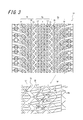
- 2 and 3 are partial development views showing tread patterns of tires of other embodiments according to the present invention, respectively.
- symbol is attached
- the tire 21 in FIG. 2 is formed by forming a circular small hole 25 having a diameter of 0.5 to 3 mm and a depth of 0.5 to 10 mm that opens in the tread surface of the block 23 and ends in the block 23 in the central land portion 5a.
- Other configurations are the same as those of the tire of the first embodiment.
- the circumferential main groove 33 extends in a zigzag shape. Further, the innermost end 35a in the tire width direction in the block 35 adjacent to the outer side in the tire width direction of the circumferential main groove 33 and the outermost end in the tire width direction in the block 37 adjacent to the inner side in the tire width direction of the circumferential main groove 33 37a is the same position in the tire width direction, and the block 35 and the block 37 are formed so as not to overlap when viewed in the tire circumferential direction.
- the edge component in the tire width direction increases, so that the traction performance and braking performance on ice and snow are improved.
- the tire does not overlap in the tire circumferential direction, and the outer end 37a is more tire than the inner end 35a. It may be located on the inner side in the width direction.
- the tires of Examples 1 to 3 and the comparative example are all radial tires for passenger cars having a size of 195 / 65R15.
- the tire of Example 1 has the tread pattern shown in FIG. 1 and specific dimensions are as shown in Table 1.
- the tire of Example 2 has the tread pattern shown in FIG. 2 and is formed with a circular small hole having a diameter of 1.5 mm that opens in the tread surface of the block and terminates in the block. This is the same as the tire of Example 1.
- the tire of Example 3 has a tread pattern shown in FIG. 3, and the circumferential main groove 33 extends in a zigzag shape. Further, the innermost end in the tire width direction in the block adjacent to the outer side in the tire width direction of the circumferential main groove 33, and the outermost end in the tire width direction in the block adjacent to the inner side in the tire width direction adjacent to the circumferential main groove 33 However, it is the same position in the tire width direction. Furthermore, the tires of Comparative Examples 1 and 2 are tires having tread patterns shown in FIGS. Specific dimensions of each tire are shown in Table 1.
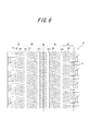
- the tire of Comparative Example 3 has a tread pattern shown in FIG. 6, and includes four circumferential main grooves 63a and 63b extending in the tire circumferential direction and five land portions 65 (tires) adjacent to the tread portion. From the center in the width direction to the central land, middle land, and shoulder land).
- the two circumferential main grooves 63a located on the inner side in the tire width direction have a width of 6.5 mm and a depth of 9.0 mm
- the two circumferential main grooves 63b located on the outer side in the tire width direction have a width of 5.0 mm. mm, depth is 9.0mm.
- a large number of blocks are formed by lateral grooves 67 that are inclined and inclined in the tread circumferential direction, and a large number of sipes 69 that are zigzag-shaped are formed in each block. .
- the evaluation results are expressed as an index with the result of Comparative Example 3 as 100, and the larger the value, the better the traction performance on ice.
- the evaluation results are shown in Table 1.
Landscapes
- Engineering & Computer Science (AREA)
- Mechanical Engineering (AREA)
- Tires In General (AREA)
Description
ここで、「トレッド接地端」とは、タイヤを正規リムに組付けて、正規内圧を充填し、正規荷重を適用した状態において、タイヤ表面が地面と接触する面のタイヤ幅方向最外位置をいう。なお、「正規リム」とは、タイヤのサイズに応じて下記の規格に規定された標準リムをいい、「正規内圧」とは、下記の規格に記載されている、適用サイズにおける単輪の最大負荷能力に対応する空気圧をいい、「正規荷重」とは、下記の規格の適用サイズにおける単輪の最大荷重(最大負荷能力)をいうものとする。そして規格とは、タイヤが生産または使用される地域に有効な産業規格であって、たとえば、日本では「日本自動車タイヤ協会」の“JATMA YEAR BOOK”であり、アメリカ合衆国では“THE TIRE AND RIM ASSOCIATION INC.”の“YEAR BOOK”であり、欧州では、“The European Tyre and Rim Technical Organisation”の“STANDARD MANUAL”である。
図1は、本発明に従う一実施形態の空気入りタイヤ(以下、「タイヤ」という)のトレッドパターンを示した部分展開図である。なお、図示は省略するが、本実施形態における空気入りタイヤは、通例に従い、一対のビード部と、ビード部のタイヤ径方向外側に連なる一対のサイドウォール部と、サイドウォール部間に跨るトレッド部とを備えるものである。また、ビード部に埋設されたビードコア間で、これら各部に亘ってトロイド状に延在するカーカスと、カーカスのクラウン部のタイヤ径方向外側にベルトが配設される。
(1)氷上ブレーキ性能評価試験
氷上でのブレーキ性能は、氷上路面のテストコースで時速20km/hからフル制動したときの制動距離を測定し、その測定した距離の逆数から評価した。評価結果は比較例3の結果を100とした指数で表し、数値が大きいほど氷上でのトラクション性能が良好であることを示す。評価結果を表1に示す。
(2)氷上トラクション性能評価試験
氷上でのトラクション性能は、氷上路面のテストコースで初速10km/hから加速し、30km/hに達するまでの時間を測定し、その測定した時間から評価した。評価結果は比較例3の結果を100とした指数で表し、数値が大きいほど氷上でのトラクション性能が良好であることを示す。評価結果を表1に示す。
(3)氷上コーナリング性能評価試験
氷上円旋回路面のテストコースでコーナリング性をドライバーのフィーリングで評価する。評価結果は比較例3の結果を100とした指数で表し、数値が大きいほど氷上でのコーナリング性能が良好であることを示す。評価結果を表1に示す。

3 周方向主溝
5a 中央陸部
5b ショルダー陸部
7a、7b 細溝
9 副溝
11 ブロック
13 拡大溝部
15 主溝開口部
17 サイプ
Claims (8)
- トレッド部に、
タイヤ周方向に延びる少なくとも1本の周方向主溝によって複数本の陸部を区画形成するとともに、
前記陸部のうちタイヤ幅方向最外側に位置するショルダー陸部に、前記周方向主溝よりも溝幅の小さい複数本の細溝と、少なくとも前記周方向主溝の近傍以外はタイヤ幅方向外側に向かうに連れて溝幅が大きくなる少なくとも1本の副溝とによって多数のブロックを区画形成し、
前記ブロックの踏面の面積が、100~200mm2の範囲であることを特徴とする空気入りタイヤ。 - 前記副溝は、前記周方向主溝及びトレッド接地端に開口してなる、請求項1に記載の空気入りタイヤ。
- 前記副溝の最小の溝幅は、前記細溝の溝幅以下である、請求項1又は2に記載の空気入りタイヤ。
- 前記副溝は、延在方向がタイヤ幅方向に対して傾斜する傾斜部を有し、
該傾斜部が、タイヤ幅方向の内側から外側に向って、タイヤ幅方向に対して傾斜するタイヤ周方向の向きが、タイヤ赤道面を境界とした両側で同一となる、請求項1~3のいずれか一項に記載の空気入りタイヤ。 - 前記細溝及び前記副溝はそれぞれ、タイヤ周方向及びタイヤ幅方向に対して傾斜する傾斜部を有し、
前記ショルダー陸部の少なくとも一部で、前記細溝の傾斜部及び前記副溝の傾斜部が交差して格子状に配置され、前記ブロックの踏面形状がそれぞれ四角形状、五角形状、六角形状、七角形状、又は八角形状のいずれかとなる、請求項1~4の何れか一項に記載の空気入りタイヤ。 - 前記細溝が交差する交差部、及び前記細溝と前記副溝が交差する交差部に、溝幅の大きい拡大溝部を有する、請求項1~5の何れか一項に記載の空気入りタイヤ。
- 前記ブロックの踏面にサイプを形成してなる、請求項1~6の何れか一項に記載の空気入りタイヤ。
- 前記細溝の溝幅が0.5~3.0mmの範囲である、請求項1~7の何れか一項に記載の空気入りタイヤ。
Priority Applications (4)
| Application Number | Priority Date | Filing Date | Title |
|---|---|---|---|
| US14/412,510 US9707804B2 (en) | 2012-07-05 | 2013-06-18 | Pneumatic tire |
| EP13813210.5A EP2871076B1 (en) | 2012-07-05 | 2013-06-18 | Pneumatic tire |
| KR1020157002761A KR101701070B1 (ko) | 2012-07-05 | 2013-06-18 | 공기식 타이어 |
| RU2015103724/11A RU2605219C2 (ru) | 2012-07-05 | 2013-06-18 | Пневматическая шина |
Applications Claiming Priority (2)
| Application Number | Priority Date | Filing Date | Title |
|---|---|---|---|
| JP2012151591A JP6012298B2 (ja) | 2012-07-05 | 2012-07-05 | 空気入りタイヤ |
| JP2012-151591 | 2012-07-05 |
Publications (1)
| Publication Number | Publication Date |
|---|---|
| WO2014006829A1 true WO2014006829A1 (ja) | 2014-01-09 |
Family
ID=49881605
Family Applications (1)
| Application Number | Title | Priority Date | Filing Date |
|---|---|---|---|
| PCT/JP2013/003795 Ceased WO2014006829A1 (ja) | 2012-07-05 | 2013-06-18 | 空気入りタイヤ |
Country Status (7)
| Country | Link |
|---|---|
| US (1) | US9707804B2 (ja) |
| EP (1) | EP2871076B1 (ja) |
| JP (1) | JP6012298B2 (ja) |
| KR (1) | KR101701070B1 (ja) |
| CN (2) | CN203472428U (ja) |
| RU (1) | RU2605219C2 (ja) |
| WO (1) | WO2014006829A1 (ja) |
Cited By (1)
| Publication number | Priority date | Publication date | Assignee | Title |
|---|---|---|---|---|
| US20190118583A1 (en) * | 2016-04-18 | 2019-04-25 | Bridgestone Corporation | Tire |
Families Citing this family (4)
| Publication number | Priority date | Publication date | Assignee | Title |
|---|---|---|---|---|
| JP6371112B2 (ja) * | 2014-05-16 | 2018-08-08 | 株式会社ブリヂストン | タイヤ |
| JP2016107728A (ja) * | 2014-12-03 | 2016-06-20 | 横浜ゴム株式会社 | 空気入りタイヤ |
| CN108349323B (zh) * | 2015-11-12 | 2020-09-22 | 株式会社普利司通 | 轮胎 |
| JP7366715B2 (ja) * | 2019-11-29 | 2023-10-23 | 株式会社ブリヂストン | タイヤ |
Citations (6)
| Publication number | Priority date | Publication date | Assignee | Title |
|---|---|---|---|---|
| JPS62196706U (ja) * | 1986-06-05 | 1987-12-14 | ||
| JPH06127217A (ja) * | 1992-10-13 | 1994-05-10 | Bridgestone Corp | 空気入りタイヤ |
| JP2002192914A (ja) | 2000-12-25 | 2002-07-10 | Yokohama Rubber Co Ltd:The | 氷雪路用空気入りタイヤ |
| JP2009113652A (ja) * | 2007-11-07 | 2009-05-28 | Yokohama Rubber Co Ltd:The | 空気入りタイヤ |
| JP2011136656A (ja) * | 2009-12-28 | 2011-07-14 | Bridgestone Corp | 空気入りタイヤ |
| JP2012066790A (ja) * | 2010-09-27 | 2012-04-05 | Sumitomo Rubber Ind Ltd | 空気入りタイヤ |
Family Cites Families (21)
| Publication number | Priority date | Publication date | Assignee | Title |
|---|---|---|---|---|
| JPS6418707A (en) * | 1987-07-15 | 1989-01-23 | Sumitomo Rubber Ind | Pneumatic tire |
| JP2755995B2 (ja) * | 1989-06-07 | 1998-05-25 | 株式会社ブリヂストン | 空気入りタイヤ |
| DE4108745A1 (de) * | 1991-03-18 | 1992-09-24 | Sp Reifenwerke Gmbh | Luftreifen |
| JP2864439B2 (ja) | 1992-12-16 | 1999-03-03 | 住友ゴム工業株式会社 | 空気入りラジアルタイヤ |
| JP2892924B2 (ja) * | 1993-11-30 | 1999-05-17 | 住友ゴム工業株式会社 | 低騒音タイヤ |
| JP4198366B2 (ja) | 2002-02-14 | 2008-12-17 | 株式会社ブリヂストン | 空気入りタイヤ |
| RU2342257C2 (ru) * | 2002-12-19 | 2008-12-27 | Пирелли Пнеуматичи С.П.А. | Рисунок протектора для зимних шин |
| JP2005349970A (ja) | 2004-06-11 | 2005-12-22 | Yokohama Rubber Co Ltd:The | 空気入りタイヤ |
| JP2006240456A (ja) | 2005-03-02 | 2006-09-14 | Bridgestone Corp | 空気入りタイヤ |
| JP5291107B2 (ja) | 2008-08-22 | 2013-09-18 | 株式会社ブリヂストン | タイヤ |
| JP5331433B2 (ja) * | 2008-10-03 | 2013-10-30 | 株式会社ブリヂストン | 空気入りタイヤ |
| JP5241422B2 (ja) * | 2008-10-16 | 2013-07-17 | 株式会社ブリヂストン | 空気入りタイヤ |
| JP5394698B2 (ja) * | 2008-11-06 | 2014-01-22 | 株式会社ブリヂストン | 空気入りタイヤ |
| EP2397345B1 (en) * | 2009-02-13 | 2014-03-19 | Bridgestone Corporation | Pneumatic tire |
| RU2492064C2 (ru) | 2009-02-24 | 2013-09-10 | Бриджстоун Корпорейшн | Шипованная шина |
| US8955564B2 (en) * | 2009-04-10 | 2015-02-17 | Bridgestone Corporation | Pneumatic tire |
| JP5368180B2 (ja) * | 2009-06-10 | 2013-12-18 | 株式会社ブリヂストン | 空気入りタイヤ |
| JP5275903B2 (ja) * | 2009-05-25 | 2013-08-28 | 株式会社ブリヂストン | 空気入りタイヤ |
| JP4755709B2 (ja) * | 2009-08-03 | 2011-08-24 | 住友ゴム工業株式会社 | 空気入りタイヤ |
| JP2011042252A (ja) * | 2009-08-21 | 2011-03-03 | Bridgestone Corp | 空気入りタイヤ |
| CN102892594B (zh) * | 2010-03-12 | 2015-09-23 | 株式会社普利司通 | 充气轮胎 |
-
2012
- 2012-07-05 JP JP2012151591A patent/JP6012298B2/ja not_active Expired - Fee Related
-
2013
- 2013-06-18 EP EP13813210.5A patent/EP2871076B1/en not_active Not-in-force
- 2013-06-18 RU RU2015103724/11A patent/RU2605219C2/ru active
- 2013-06-18 US US14/412,510 patent/US9707804B2/en active Active
- 2013-06-18 KR KR1020157002761A patent/KR101701070B1/ko not_active Expired - Fee Related
- 2013-06-18 WO PCT/JP2013/003795 patent/WO2014006829A1/ja not_active Ceased
- 2013-07-04 CN CN201320396382.5U patent/CN203472428U/zh not_active Expired - Fee Related
- 2013-07-04 CN CN201310279352.0A patent/CN103522845B/zh not_active Expired - Fee Related
Patent Citations (6)
| Publication number | Priority date | Publication date | Assignee | Title |
|---|---|---|---|---|
| JPS62196706U (ja) * | 1986-06-05 | 1987-12-14 | ||
| JPH06127217A (ja) * | 1992-10-13 | 1994-05-10 | Bridgestone Corp | 空気入りタイヤ |
| JP2002192914A (ja) | 2000-12-25 | 2002-07-10 | Yokohama Rubber Co Ltd:The | 氷雪路用空気入りタイヤ |
| JP2009113652A (ja) * | 2007-11-07 | 2009-05-28 | Yokohama Rubber Co Ltd:The | 空気入りタイヤ |
| JP2011136656A (ja) * | 2009-12-28 | 2011-07-14 | Bridgestone Corp | 空気入りタイヤ |
| JP2012066790A (ja) * | 2010-09-27 | 2012-04-05 | Sumitomo Rubber Ind Ltd | 空気入りタイヤ |
Cited By (1)
| Publication number | Priority date | Publication date | Assignee | Title |
|---|---|---|---|---|
| US20190118583A1 (en) * | 2016-04-18 | 2019-04-25 | Bridgestone Corporation | Tire |
Also Published As
| Publication number | Publication date |
|---|---|
| CN103522845A (zh) | 2014-01-22 |
| CN203472428U (zh) | 2014-03-12 |
| CN103522845B (zh) | 2016-08-10 |
| RU2605219C2 (ru) | 2016-12-20 |
| US9707804B2 (en) | 2017-07-18 |
| US20150191049A1 (en) | 2015-07-09 |
| EP2871076A1 (en) | 2015-05-13 |
| RU2015103724A (ru) | 2016-08-27 |
| JP2014015057A (ja) | 2014-01-30 |
| JP6012298B2 (ja) | 2016-10-25 |
| KR20150036328A (ko) | 2015-04-07 |
| EP2871076A4 (en) | 2016-04-06 |
| KR101701070B1 (ko) | 2017-01-31 |
| EP2871076B1 (en) | 2017-10-11 |
Similar Documents
| Publication | Publication Date | Title |
|---|---|---|
| US10836215B2 (en) | Tire | |
| EP3081397A1 (en) | Pneumatic tire | |
| JP5770834B2 (ja) | 雪上用空気入りタイヤ | |
| KR102377656B1 (ko) | 공기 타이어 | |
| JP6139843B2 (ja) | 空気入りタイヤ | |
| JP6088336B2 (ja) | 空気入りタイヤ | |
| JP6012298B2 (ja) | 空気入りタイヤ | |
| JP7176320B2 (ja) | タイヤ | |
| CN113799544A (zh) | 轮胎 | |
| WO2015004888A1 (ja) | 空気入りタイヤ | |
| JP5814042B2 (ja) | 空気入りタイヤ | |
| JP2017095085A (ja) | 空気入りタイヤ | |
| CN106427402B (zh) | 充气轮胎 | |
| JP5200123B2 (ja) | 重荷重用空気入りタイヤ | |
| JP2016037083A (ja) | 空気入りタイヤ | |
| CN114643809B (zh) | 充气轮胎 | |
| WO2014083758A1 (ja) | 空気入りタイヤ | |
| JP6060221B2 (ja) | 空気入りタイヤ | |
| JP2015178337A (ja) | 空気入りタイヤ | |
| JP6416024B2 (ja) | 空気入りタイヤ | |
| JP6254342B2 (ja) | 空気入りタイヤ | |
| JP2014151748A (ja) | 空気入りタイヤ | |
| JPWO2019111756A1 (ja) | タイヤ | |
| JP6299078B2 (ja) | 空気入りタイヤ | |
| JP5437851B2 (ja) | 空気入りタイヤ |
Legal Events
| Date | Code | Title | Description |
|---|---|---|---|
| 121 | Ep: the epo has been informed by wipo that ep was designated in this application |
Ref document number: 13813210 Country of ref document: EP Kind code of ref document: A1 |
|
| REEP | Request for entry into the european phase |
Ref document number: 2013813210 Country of ref document: EP |
|
| WWE | Wipo information: entry into national phase |
Ref document number: 2013813210 Country of ref document: EP |
|
| WWE | Wipo information: entry into national phase |
Ref document number: 14412510 Country of ref document: US |
|
| NENP | Non-entry into the national phase |
Ref country code: DE |
|
| ENP | Entry into the national phase |
Ref document number: 20157002761 Country of ref document: KR Kind code of ref document: A |
|
| ENP | Entry into the national phase |
Ref document number: 2015103724 Country of ref document: RU Kind code of ref document: A |