WO2014007094A1 - 復号装置および方法、符号化装置および方法、並びにプログラム - Google Patents
復号装置および方法、符号化装置および方法、並びにプログラム Download PDFInfo
- Publication number
- WO2014007094A1 WO2014007094A1 PCT/JP2013/067230 JP2013067230W WO2014007094A1 WO 2014007094 A1 WO2014007094 A1 WO 2014007094A1 JP 2013067230 W JP2013067230 W JP 2013067230W WO 2014007094 A1 WO2014007094 A1 WO 2014007094A1
- Authority
- WO
- WIPO (PCT)
- Prior art keywords
- unit
- audio data
- information
- sound source
- source position
- Prior art date
- Legal status (The legal status is an assumption and is not a legal conclusion. Google has not performed a legal analysis and makes no representation as to the accuracy of the status listed.)
- Ceased
Links
Images










Classifications
-
- G—PHYSICS
- G10—MUSICAL INSTRUMENTS; ACOUSTICS
- G10L—SPEECH ANALYSIS TECHNIQUES OR SPEECH SYNTHESIS; SPEECH RECOGNITION; SPEECH OR VOICE PROCESSING TECHNIQUES; SPEECH OR AUDIO CODING OR DECODING
- G10L19/00—Speech or audio signals analysis-synthesis techniques for redundancy reduction, e.g. in vocoders; Coding or decoding of speech or audio signals, using source filter models or psychoacoustic analysis
- G10L19/008—Multichannel audio signal coding or decoding using interchannel correlation to reduce redundancy, e.g. joint-stereo, intensity-coding or matrixing
-
- G—PHYSICS
- G10—MUSICAL INSTRUMENTS; ACOUSTICS
- G10L—SPEECH ANALYSIS TECHNIQUES OR SPEECH SYNTHESIS; SPEECH RECOGNITION; SPEECH OR VOICE PROCESSING TECHNIQUES; SPEECH OR AUDIO CODING OR DECODING
- G10L19/00—Speech or audio signals analysis-synthesis techniques for redundancy reduction, e.g. in vocoders; Coding or decoding of speech or audio signals, using source filter models or psychoacoustic analysis
- G10L19/04—Speech or audio signals analysis-synthesis techniques for redundancy reduction, e.g. in vocoders; Coding or decoding of speech or audio signals, using source filter models or psychoacoustic analysis using predictive techniques
- G10L19/16—Vocoder architecture
- G10L19/167—Audio streaming, i.e. formatting and decoding of an encoded audio signal representation into a data stream for transmission or storage purposes
-
- H—ELECTRICITY
- H03—ELECTRONIC CIRCUITRY
- H03M—CODING; DECODING; CODE CONVERSION IN GENERAL
- H03M7/00—Conversion of a code where information is represented by a given sequence or number of digits to a code where the same, similar or subset of information is represented by a different sequence or number of digits
- H03M7/30—Compression; Expansion; Suppression of unnecessary data, e.g. redundancy reduction
-
- H—ELECTRICITY
- H04—ELECTRIC COMMUNICATION TECHNIQUE
- H04S—STEREOPHONIC SYSTEMS
- H04S3/00—Systems employing more than two channels, e.g. quadraphonic
- H04S3/008—Systems employing more than two channels, e.g. quadraphonic in which the audio signals are in digital form, i.e. employing more than two discrete digital channels
-
- H—ELECTRICITY
- H04—ELECTRIC COMMUNICATION TECHNIQUE
- H04S—STEREOPHONIC SYSTEMS
- H04S5/00—Pseudo-stereo systems, e.g. in which additional channel signals are derived from monophonic signals by means of phase shifting, time delay or reverberation
- H04S5/02—Pseudo-stereo systems, e.g. in which additional channel signals are derived from monophonic signals by means of phase shifting, time delay or reverberation of the pseudo four-channel type, e.g. in which rear channel signals are derived from two-channel stereo signals
-
- H—ELECTRICITY
- H04—ELECTRIC COMMUNICATION TECHNIQUE
- H04S—STEREOPHONIC SYSTEMS
- H04S2400/00—Details of stereophonic systems covered by H04S but not provided for in its groups
- H04S2400/03—Aspects of down-mixing multi-channel audio to configurations with lower numbers of playback channels, e.g. 7.1 -> 5.1
-
- H—ELECTRICITY
- H04—ELECTRIC COMMUNICATION TECHNIQUE
- H04S—STEREOPHONIC SYSTEMS
- H04S2400/00—Details of stereophonic systems covered by H04S but not provided for in its groups
- H04S2400/11—Positioning of individual sound objects, e.g. moving airplane, within a sound field
Definitions
- the present technology relates to a decoding apparatus and method, an encoding apparatus and method, and a program, and in particular, a decoding apparatus and method, an encoding apparatus and method, and a program that can obtain more realistic high-quality speech.
- a decoding apparatus and method an encoding apparatus and method, and a program that can obtain more realistic high-quality speech.
- next-generation high-definition video with more pixels is being studied for higher image quality, and the audio part also exceeds 5.1 multi-channel, and in order to achieve a more realistic sensation in the plane and vertical directions. Channel expansion in the direction is expected.
- This technology has been made in view of such a situation, and is intended to obtain a higher quality voice with a more realistic feeling.
- a decoding device includes a decoding unit that decodes audio data included in an encoded bitstream, and an area in which the arbitrary data of the encoded bitstream can be stored.
- a reading unit that reads sound source position information related to the height of the sound source, and an output unit that outputs the decoded audio data based on the sound source position information.
- the sound source position information may be information indicating whether the height of the sound source is substantially the same as that of the user, above the user, or below the user.
- Identification information for identifying presence / absence of the sound source position information is stored in the area in which the arbitrary data can be stored, and the reading unit reads the sound source position information based on the identification information. Can be.
- first identification information determined in advance and second identification information calculated based on the sound source position information are stored as the identification information. Can be.
- the first identification information included in the area where the arbitrary data can be stored is predetermined specific information, and is read from the area where the arbitrary data can be stored
- the second identification information matches the second identification information calculated based on the read sound source position information
- the sound source position information can be regarded as valid information.
- the second identification information can be calculated based on information obtained by performing byte alignment on information including the sound source position information.
- the decoding method or program according to the first aspect of the present technology decodes audio data included in an encoded bitstream and generates a sound source of the audio data from an area in which arbitrary data of the encoded bitstream can be stored. Reading out the sound source position information relating to the height of the sound source, and outputting the decoded audio data based on the sound source position information.
- the audio data included in the encoded bitstream is decoded, and the sound source height of the audio data is related to an area where arbitrary data of the encoded bitstream can be stored.
- Sound source position information is read, and the decoded audio data is output based on the sound source position information.
- An encoding device includes an acquisition unit that acquires sound source position information regarding the height of a sound source, an encoding unit that encodes audio data and the sound source position information, and the encoded sound source The position information is stored in an area where arbitrary data can be stored, and the packing unit generates the encoded bit stream including the encoded audio data and the sound source position information.
- the sound source position information may be information indicating whether the height of the sound source is substantially the same as that of the user, above the user, or below the user.
- identification information for identifying presence / absence of the sound source position information can be stored together with the sound source position information.
- first identification information determined in advance and second identification information calculated based on the sound source position information are stored as the identification information. can do.
- information for instructing execution of byte alignment for information including the sound source position information, and the second identification information calculated based on the information obtained by the byte alignment And information instructing collation with the second identification information stored in the area where the arbitrary data can be stored can be further stored.
- the encoding method or program according to the second aspect of the present technology acquires sound source position information related to the height of a sound source, encodes audio data and the sound source position information, and converts the encoded sound source position information into an arbitrary sound source position information. Storing the data in a storable area and generating an encoded bitstream including the encoded audio data and the sound source position information.
- sound source position information related to the height of a sound source is acquired, audio data and the sound source position information are encoded, and the encoded sound source position information can store arbitrary data.
- An encoded bit stream including the encoded audio data and the sound source position information is generated in a separate area.
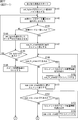
- positioning It is a figure which shows an example of speaker mapping. It is a figure explaining an encoding bit stream. It is a figure which shows the syntax of height_extension_element. It is a figure explaining the arrangement
- This technology relates to encoding and decoding of audio data.
- MPEG-2 AAC and MPEG-4 AAC standard multi-channel coding cannot have information for channel expansion in the horizontal and vertical directions.
- these multi-channel encodings do not have channel down-mixed content downmix information, and the appropriate mixing ratio of each channel is unknown, making it difficult to hear the playback sound on a portable device with a small number of playback channels. End up.
- the following features (1) to (4) make it possible to obtain high-quality audio with a more realistic feeling.
- FIG. 1 it is assumed that the user observes the display screen TVS of a display device such as a television receiver from the front. That is, it is assumed that the user is located on the near side in the figure of the display screen TVS.
- audio data (sound) channels reproduced by these speakers Lvh, Rvh, Lrs, Ls, L, Lc, C, Rc, R, Rs, Rrs, Cs, and LFE are respectively represented by Lvh, Rvh, Lrs. , Ls, L, Lc, C, Rc, R, Rs, Rrs, Cs, LFE.
- channel L is “Front Left”
- channel R is “Front Right”
- channel C is “Front Center”.
- channel Ls is “LeftroundSurround”
- channel Rs is “Right Surround”
- channel Lrs is “Left Rear”
- channel Rrs is “Right Rear”
- channel Cs is “Center Back” is there.
- the channel Lvh is “Left High Front”
- the channel Rvh is “Right High Front”
- the channel LFE is “Low-Frequency-Effect”.
- the speaker Lvh and the speaker Rvh are respectively arranged on the left and right on the front upper side of the user, and the layer in which these speakers Rvh and Lvh are arranged is “Top layer”.
- Speakers L, C, and R are disposed on the left side, center, and right side in front of the user, respectively. Speakers Lc and Rc are disposed between speakers L and C, and between speakers R and C, respectively. ing. Furthermore, the speakers Ls and Rs are respectively disposed on the left and right sides of the user, and the speakers Lrs, Rrs and Cs are respectively disposed on the rear left side, the rear right side and the rear side of the user.
- These speakers Lrs, Ls, L, Lc, C, Rc, R, Rs, Rrs, and Cs are arranged so as to surround the user on a plane located approximately at the height of the user's ear, and these speakers
- the layer where the speaker is arranged is “Middle layer”.
- the speaker LFE is disposed on the lower front side of the user, and the layer on which the speaker LFE is disposed is “LFE layer”.
- FIG. 3 shows the syntax of the encoded bit stream of the AAC frame.
- the encoded bitstream of FIG. 3 includes “Header / sideinfo”, “PCE”, “SCE”, “CPE”, “LFE”, “DSE”, “FIL (DRC)”, and “FIL (END)”.
- the encoded bitstream includes three “CPEs”.
- “PCE” includes information on each channel of audio data.
- a certain “Height Infomation” is included.
- “PCE” includes “comment_field_data” that is a comment area (comment field) in which a free comment can be stored, and “comment_field_data” includes “height_extension_element” that is an extension area.
- the comment area is an area in which arbitrary data such as general comments can be stored.
- This “height_extension_element” includes “Height Infomation” that is information related to the height of the speaker arrangement.
- SCE contains single-channel audio data
- CPE contains channel pairs, that is, two channels of audio data
- LFE contains LFE channel audio data.
- SCE stores audio data of channels such as C and Cs
- CPE stores audio data of channels such as L, R, Lvh, and Rvh.
- DSE is an ancillary data area
- DSE stores free data.
- the information about the downmix of the audio data is “Downmix 5.1ch to 2ch”, ”Dynamic Range Control”, ⁇ DRC Presentation Mode '', ⁇ Downmix 6.1ch 7.1 5.1ch '' global gain downmixing ”and“ LFE downmixing ”are included.
- FIL (DRC) includes information related to audio dynamic range control.
- FIL (DRC) includes “Program Reference Level” and “Dynamic Range Control”.
- “comment_field_data” of “PCE” includes “height_extension_element”, thereby realizing multi-channel reproduction based on speaker arrangement information in the vertical direction. That is, high-quality sound reproduction with a more realistic sensation can be performed by the speakers arranged in each height layer such as “Top layer” and “Middle layer”.
- FIG. 4 is a diagram illustrating the syntax of “height_extension_element”.
- PCE_HEIGHT_EXTENSION_SYNC indicates a synchronization word.
- front_element_height_info [i]”, “side_element_height_info [i]”, and “back_element_height_info [i]” indicate the height, that is, the layer of each speaker located in front, side, and rear as viewed from the viewer. ing.
- “byte_alignment ()” indicates that byte alignment is performed
- “height_info_crc_check” indicates a CRC check code used as identification information.
- a CRC check code is calculated based on information read between “PCE_HEIGHT_EXTENSION_SYNC” and “byte_alignment ()”, that is, the synchronization word, the arrangement information of each speaker (information of each channel), and byte alignment. Then, it is determined whether or not the calculated CRC check code matches the CRC check code indicated by “height_info_crc_check”. If they match, it is assumed that the information regarding the arrangement of each speaker has been correctly read.
- front_element_height_info [i]”, “side_element_height_info [i]”, and “back_element_height_info [i]”, which are information related to the position of the sound source, that is, the speaker arrangement (height), are determined as shown in FIG. .
- DSE that is, “MPEG4 ancillary data” that is an ancillary data area included in “data_stream_byte []” of “data_stream_element ()” will be described.
- This “MPEG4 ancillary data” enables downmix DRC control from 6.1 channels or 7.1 channels of audio data to 5.1 channels or 2 channels.
- FIG. 6 shows the syntax of “MPEG4 ancillary data”.
- “MPEG4 ancillary data” includes “bs_info ()”, “ancillary_data_status ()”, “downmixing_levels_MPEG4 ()”, “audio_coding_mode ()”, “Compression_value”, and “MPEG4_ext_ancillary_data ()”.
- “Compression_value” corresponds to “Dynamic Range Control” in FIG.
- the syntax of “bs_info ()”, “ancillary_data_status ()”, “downmixing_levels_MPEG4 ()”, “audio_coding_mode ()”, and “MPEG4_ext_ancillary_data ()” is as shown in FIGS. 7 to 11, respectively. .
- “bs_info ()” includes “mpeg_audio_type”, “dolby_surround_mode”, “drc_presentation_mode”, and “pseudo_surround_enable” as shown in FIG.
- Drc_presentation_mode corresponds to “DRC Presentation Mode” shown in FIG.
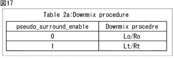
- “pseudo_surround_enable” includes information indicating the downmix processing procedure from 5.1 channel to 2 channels, that is, information indicating which of the plurality of downmix processing methods is used for downmixing. Yes.
- ancillary_data_extension_status included in “ancillary_data_status ()” shown in FIG. 8 is 0 or 1.
- ancillary_data_extension_status is 1, “MPEG4_ext_ancillary_data ()” in “MPEG4PEGancillaryilldata” in FIG. 6 is accessed, and downmix DRC control is performed.
- ancillary_data_extension_status is 0, the conventional processing is performed. Thereby, compatibility with existing standards can be ensured.
- “Downmixing_levels_MPEG4_status” included in “ancillary_data_status ()” in FIG. 8 is information for specifying a coefficient (mixing ratio) used for downmixing from 5.1 channel to 2 channels. That is, when “downmixing_levels_MPEG4_status” is 1, downmixing is performed using a coefficient determined by information stored in “downmixing_levels_MPEG4 ()” shown in FIG.
- “Downmixing_levels_MPEG4 ()” in FIG. 9 includes “center_mix_level_value” and “surround_mix_level_value” as information for specifying the downmix coefficient.
- the values of the coefficients corresponding to “center_mix_level_value” and “surround_mix_level_value” are determined by, for example, a table shown in FIG.
- MPEG4_ext_ancillary_data () in FIG. 11 includes “ext_ancillary_data_status ()”, “ext_downmixing_levels ()”, “ext_downmixing_global_gains ()”, and “ext_downmixing_lfe_level ()”.
- MPEG4_ext_ancillary_data () stores information necessary for expanding the number of channels so that 7.1 or 6.1 channels of audio data can be handled compared to 5.1 channels of audio data.
- “ext_ancillary_data_status ()” includes information (flag) indicating whether or not downmixing from more than 5.1 channels to 5.1 channels is performed, and information indicating whether gain control is performed during downmixing Information indicating whether to use the LFE channel for downmixing is included.
- Ext_downmixing_levels () stores information for specifying the coefficients (mixing ratio) used when downmixing
- “ext_downmixing_global_gains ()” contains information about gains during gain adjustment. It is. Further, “ext_downmixing_lfe_level ()” stores information for specifying the coefficient (mixing ratio) of the LEF channel used when downmixing is performed.
- “ext_ancillary_data_status ()” is as shown in FIG.
- “ext_ancillary_data_status ()” indicates whether or not to downmix from 6.1 channel or 7.1 channel to 5.1 channel. That is, it indicates whether or not “ext_downmixing_levels ()” exists.
- This “ext_downmixing_levels_status” corresponds to “Downmix 6.1ch and 7.1ch to 5.1ch” in FIG.
- ext_downmixing_global_gains_status indicates whether or not to perform global gain control, and corresponds to “global gain downmixing” in FIG. That is, it indicates whether or not “ext_downmixing_global_gains ()” exists.
- Ext_downmixing_lfe_level_status indicates whether or not the LFE channel is used when downmixing from 5.1 channel to 2 channels, and corresponds to “LFE downmixing” in FIG.
- “ext_downmixing_global_gains ()” in FIG. 15 includes “dmx_gain_5_sign” indicating the sign of gain when downmixing to 5.1 channel, gain “dmx_gain_5_idx”, gain when performing downmixing to two channels “Dmx_gain_2_sign” indicating the sign of “dmx” and its gain “dmx_gain_2_idx” are included.
- dmix_lfe_idx is included in “ext_downmixing_lfe_level ()” of FIG. 16, and this “dmix_lfe_idx” is information indicating the mixing ratio (coefficient) of the LFE channel during downmixing.
- the downmix from 5.1 channel to 2 channels will be explained.
- the L channel and the R channel after downmixing are the L ′ channel and the R ′ channel, respectively, the following processing is performed.
- L, R, C, Ls, Rs, and LFE are channels constituting the 5.1 channel, and L, described with reference to FIGS. 1 and 2, respectively. R, C, Ls, Rs, and LFE channels are shown.
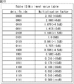
- c is a constant determined by the value of “dmix_lfe_idx” included in “ext_downmixing_lfe_level ()” shown in FIG. 16, for example, a constant for each value of “dmix_lfe_idx”
- the value of c is as shown in FIG.
- the LFE channel is not used for the calculations of Expressions (1) and (2).
- “ext_downmixing_lfe_level_status” is 1, the value of the constant c multiplied by the LFE channel is determined based on the table shown in FIG.
- a and b are constants determined by the values of “dmix_a_idx” and “dmix_b_idx” included in “ext_downmixing_levels ()” shown in FIG.
- a and b in Expression (1) and Expression (2) may be constants determined by the values of “center_mix_level_value” and “surround_mix_level_value” in “downmixing_levels_MPEG4 ()” illustrated in FIG.
- the values of constants a and b for each value of “dmix_a_idx” and “dmix_b_idx” or “center_mix_level_value” and “surround_mix_level_value” are as shown in FIG.
- “dmix_a_idx” and “dmix_b_idx” and “center_mix_level_value” and “surround_mix_level_value” refer to the same table, so the values of a and b that are constants (coefficients) for downmixing are the same. Become.
- the audio data of channels C, L, R, Ls, Rs, Lrs, Rrs, and LFE, including the channels of speakers Lrs and Rrs behind the user, are C ', L', R ', Ls', and Rs'.
- LFE ′ is converted to 5.1 channel audio data, the following equation (3) is calculated.
- d1 and d2 are constants, and these constants d1 and d2 are constants determined for each value of “dmix_a_idx” and “dmix_b_idx” shown in FIG. 19, for example. .
- channels C, L, R, Lc, Rc, Ls, Rs, and LFE including the channels of speakers Lc and Rc in front of the user, are C ′, L ′, R ′, Ls ′
- channels C ′, L ′, R ′, Ls ′, Rs ′, and LFE ′ represent channels C, L, R, Ls, Rs, and LFE after downmixing.
- C, L, R, Lc, Rc, Ls, Rs, and LFE indicate audio data of channels C, L, R, Lc, Rc, Ls, Rs, and LFE.
- e1 and e2 are constants, and these constants e1 and e2 are constants determined for each value of “dmix_a_idx” and “dmix_b_idx” shown in FIG. 19, for example. .
- channels C, L, R, Lvh, Rvh, Ls, Rs, and LFE including the channels of speakers Rvh and Lvh on the upper front side as viewed from the user
- channels C ′, L ′, R ′, and Ls ′ represent channels C, L, R, Ls, Rs, and LFE after downmixing.
- C, L, R, Lvh, Rvh, Ls, Rs, and LFE indicate audio data of channels C, L, R, Lvh, Rvh, Ls, Rs, and LFE.
- f1 and f2 are constants, and these constants f1 and f2 are constants determined for each value of “dmix_a_idx” and “dmix_b_idx” shown in FIG. 19, for example. .
- channels C, L, R, Ls, Rs, Cs, and LFE are converted into 5.1 channel audio data consisting of C ′, L ′, R ′, Ls ′, Rs ′, and LFE ′
- channels C ′, L ′, R ′, Ls ′, Rs ′, and LFE ′ represent channels C, L, R, Ls, Rs, and LFE after downmixing.
- C, L, R, Ls, Rs, Cs, and LFE indicate audio data of channels C, L, R, Ls, Rs, Cs, and LFE.
- Equation (6) g1 and g2 are constants, and these constants g1 and g2 are constants determined for each value of “dmix_a_idx” and “dmix_b_idx” shown in FIG. 19, for example. .
- the global downmix gain is used to correct the volume of audio that has become larger or smaller due to downmixing.
- dmx_gain5 indicates a correction value for downmix from 7.1 channel or 6.1 channel to 5.1 channel
- dmx_gain2 indicates a correction value for downmix from 5.1 channel to 2 channels.
- Dmx_gain2 also supports decoding devices and bitstreams that do not support 7.1 channels.
- the encoding apparatus can appropriately evaluate a long period or a very short period of the audio frame as appropriate, and determine a global downmix gain.
- dmx_gain5 + dmx_gain2 the gain is combined, that is, (dmx_gain5 + dmx_gain2) is applied.
- dmx_gain5 and dmx_gain2 are quantized in increments of 0.25 dB using 6-bit unsigned integers.
- dmx_gain5 and dmx_gain2 has a value in the range of ⁇ 15.75 dB. These are gain values applied to the decoded sample of audio data of the current frame.
- dmx_gain5 is a scalar value, which is a gain value obtained from the following equation (8) from “dmx_gain_5_sign” and “dmx_gain_5_idx” shown in FIG.
- dmx_gain2 is a scalar value, which is a gain value obtained by the following equation (10) from “dmx_gain_2_sign” and “dmx_gain_2_idx” shown in FIG.
- the gain value dmx_gain_7to2 applied to the audio data can be obtained by combining dmx_gain5 and dmx_gain2, as shown in the following equation (11).
- Dmx_gain_7to2 dmx_gain_2 ⁇ dmx_gain_5 (11)
- downmixing from 6.1 channels to 2 channels is the same as downmixing from 7.1 channels to 2 channels.
- Equation (7) and Equation (9) when downmixing from 7.1 channel to 2 channels, calculation of Equation (7) and Equation (9) is performed, and when gain correction is performed in two stages, 5.1 channel audio data and 2 channels Audio data can be output.
- FIG. 20 is a diagram illustrating the syntax of “drc_presentation_mode”.
- FIG. 22 is a diagram illustrating a configuration example of an embodiment of an encoding device to which the present technology is applied.
- the encoding device 11 includes an input unit 21, an encoding unit 22, and a packing unit 23.
- the input unit 21 obtains audio data and information related to the audio data from the outside and supplies them to the encoding unit 22. For example, information on the arrangement (arrangement height) of speakers is acquired as information on audio data.
- the encoding unit 22 encodes the audio data supplied from the input unit 21 and information related to the audio data, and supplies the encoded data to the packing unit 23.
- the packing unit 23 packs the audio data supplied from the encoding unit 22 and information related to the audio data, generates the encoded bit stream shown in FIG. 3, and outputs the encoded bit stream.
- step S11 the input unit 21 acquires audio data and information related to the audio data and supplies the acquired audio data to the encoding unit 22.
- audio data of each channel of 7.1 channels, information on speaker arrangement (hereinafter referred to as speaker arrangement information) stored in “height_extension_element” illustrated in FIG. 4 and the like are acquired.
- step S12 the encoding unit 22 encodes the audio data of each channel supplied from the input unit 21.
- step S13 the encoding unit 22 encodes the speaker arrangement information supplied from the input unit 21.
- the encoding unit 22 generates a synchronization word stored in “PCE_HEIGHT_EXTENSION_SYNC” included in “height_extension_element” in FIG. 4 or generates a CRC check code that is identification information stored in “height_info_crc_check”. Then, these synchronization words and CRC check codes are supplied to the packing unit 23 together with the encoded speaker arrangement information.
- the encoding unit 22 generates information necessary for generating an encoded bit stream, and supplies the information to the packing unit 23 together with the encoded audio data and speaker arrangement information.
- step S14 the packing unit 23 performs bit packing on the audio data and speaker arrangement information supplied from the encoding unit 22 to generate and output the encoded bit stream of FIG.
- the packing unit 23 stores speaker arrangement information, a synchronization word, a CRC check code, and the like in “PCE”, and stores audio data in “SCE” and “CPE”.
- the encoding device 11 includes the speaker arrangement information, which is information relating to the speaker arrangement in each layer, in the encoded bitstream, and outputs encoded audio data.
- the speaker arrangement information is information relating to the speaker arrangement in each layer, in the encoded bitstream, and outputs encoded audio data.
- FIG. 24 is a diagram illustrating a configuration example of such a decoding device.
- the decoding device 51 includes a separation unit 61, a decoding unit 62, and an output unit 63.
- the separating unit 61 receives the encoded bit stream transmitted from the encoding device 11, bit unpacks the encoded bit stream, and supplies the encoded bit stream to the decoding unit 62.
- the decoding unit 62 decodes the encoded bit stream supplied from the separation unit 61, that is, audio data of each channel, speaker arrangement information, and the like, and supplies the audio data obtained by the decoding to the output unit 63.
- the decoding unit 62 also performs downmixing of audio data as necessary.
- the output unit 63 outputs the audio data supplied from the decoding unit 62 according to the speaker arrangement (speaker mapping) instructed by the decoding unit 62.
- the audio data of each channel output from the output unit 63 is supplied to the speaker of each channel and reproduced.
- step S41 the decoding unit 62 decodes the audio data.
- the separating unit 61 receives the encoded bit stream transmitted from the encoding device 11 and bit unpacks the encoded bit stream. Then, the separation unit 61 supplies the audio data obtained by bit unpacking and various pieces of information such as speaker arrangement information to the decoding unit 62. The decoding unit 62 decodes the audio data supplied from the separation unit 61 and supplies the decoded audio data to the output unit 63.
- step S42 the decoding unit 62 detects a synchronization word from the information supplied from the separation unit 61. Specifically, the synchronization word is detected from “height_extension_element” in FIG.
- step S43 the decoding unit 62 determines whether or not a synchronization word has been detected. If it is determined in step S43 that a synchronization word has been detected, the decoding unit 62 decodes the speaker arrangement information in step S44.
- the decoding unit 62 reads information such as “front_element_height_info [i]”, “side_element_height_info [i]”, “back_element_height_info [i]” from “height_extension_element” illustrated in FIG. As a result, it is understood which position (channel) the audio data should be reproduced by the speaker.
- step S45 the decoding unit 62 generates identification information. That is, the decoding unit 62 calculates a CRC check code based on information read from “PCE_HEIGHT_EXTENSION_SYNC” to “byte_alignment ()” of “height_extension_element”, that is, synchronization word, speaker arrangement information, and byte alignment. And identification information.
- step S46 the decoding unit 62 compares the identification information generated in step S45 with the identification information included in “height_info_crc_check” of “height_extension_element” illustrated in FIG. Determine whether or not.
- step S46 When it is determined in step S46 that the identification information matches, the decoding unit 62 supplies the audio data obtained by the decoding to the output unit 63, and outputs the audio data based on the obtained speaker arrangement information. The process proceeds to step S47.
- step S47 the output unit 63 outputs the audio data supplied from the decoding unit 62 according to the speaker arrangement (speaker mapping) instructed by the decoding unit 62, and the decoding process ends.
- step S48 the output unit 63 uses a predetermined speaker arrangement for audio. Output data.
- step S48 is performed when the speaker arrangement information cannot be read correctly from “height_extension_element”.
- the decoding unit 62 supplies the audio data to the output unit 63 and instructs the output of the audio data so that the audio data of each channel is reproduced by the speaker of each predetermined channel. .
- the output unit 63 outputs audio data according to the instruction of the decoding unit 62, and the decoding process ends.
- the decoding device 51 decodes audio data and speaker arrangement information included in the encoded bitstream, and outputs audio data based on the speaker arrangement information. Since the speaker arrangement information includes information related to the arrangement of the speakers in the vertical direction, it is possible to reproduce not only a plane but also a sound image in the vertical direction, and audio reproduction with a higher sense of presence is possible.
- processing such as audio data downmixing is also performed as necessary.
- the decoding unit 62 reads “MPEG4_ext_ancillary_data ()”. Then, the decoding unit 62 reads each piece of information included in “MPEG4_ext_ancillary_data ()” shown in FIG. 11, and performs audio data downmix and gain correction.
- the decoding unit 62 downmixes 7.1-channel or 6.1-channel audio data into 5.1-channel audio data, and further downmixes 5.1-channel audio data into 2-channel audio data.
- the decoding unit 62 uses the audio data of the LFE channel for downmixing as necessary.
- the coefficient to be multiplied by each channel is determined with reference to “ext_downmixing_levels ()” shown in FIG. 13 and “ext_downmixing_lfe_level ()” shown in FIG. Further, “ext_downmixing_global_gains ()” shown in FIG. 15 is referred to for gain correction during downmixing.
- FIG. 26 is a diagram illustrating a more detailed configuration example of the encoding device.
- the encoding device 91 includes an input unit 21, an encoding unit 22, and a packing unit 23.
- portions corresponding to those in FIG. 22 are denoted by the same reference numerals, and description thereof will be omitted as appropriate.
- the encoding unit 22 includes a PCE encoding unit 101, a DSE encoding unit 102, and an audio element encoding unit 103.
- the PCE encoding unit 101 performs PCE encoding based on the information supplied from the input unit 21. That is, the PCE encoding unit 101 generates each piece of information stored in the PCE while encoding each piece of information as necessary.
- the PCE encoding unit 101 includes a synchronization word encoding unit 111, an arrangement information encoding unit 112, and an identification information encoding unit 113.
- the synchronization word encoding unit 111 encodes the synchronization word, and uses the encoded synchronization word as information stored in the extension area included in the comment area of the PCE.
- the arrangement information encoding unit 112 encodes speaker arrangement information indicating the height (layer) of the speaker for each audio data supplied from the input unit 21, and uses the information as information stored in the extension area in the comment area. .
- the identification information encoding unit 113 encodes identification information. For example, the identification information encoding unit 113 generates a CRC check code as identification information based on the synchronization word and the speaker arrangement information as necessary, and uses the CRC check code as information stored in the extension area in the comment area.
- the DSE encoding unit 102 performs DSE encoding based on the information supplied from the input unit 21. That is, the DSE encoding unit 102 generates each piece of information stored in the DSE while encoding each piece of information as necessary.
- the DSE encoding unit 102 includes an extension information encoding unit 114 and a downmix information encoding unit 115.
- the extension information encoding unit 114 encodes information (flag) indicating whether or not extension information is included in “MPEG4_ext_ancillary_data ()” that is an extension area of DSE.
- the downmix information encoding unit 115 encodes information regarding the downmix of audio data.
- the audio element encoding unit 103 encodes the audio data supplied from the input unit 21.
- the encoding unit 22 supplies information stored in each element obtained by encoding various data to the packing unit 23.
- step S71 the input unit 21 acquires audio data and information necessary for encoding the audio data and supplies the acquired audio data to the encoding unit 22.
- the input unit 21 indicates PCM (Pulse Code Modulation) data of each channel as audio data, information indicating the speaker arrangement of each channel, information for specifying a downmix coefficient, and the bit rate of the encoded bit stream.
- PCM Pulse Code Modulation
- the information for specifying the downmix coefficient is multiplied by the audio data of each channel when downmixing from 7.1 or 6.1 channels to 5.1 channels and from 5.1 channels to 2 channels. It is information indicating a coefficient.
- the input unit 21 acquires the file name of the encoded bit stream to be obtained from now. This file name is appropriately used by the encoding device.
- step S72 the audio element encoding unit 103 encodes the audio data supplied from the input unit 21, and sets the data to be stored in each element of SCE, CPE, and LFE. At this time, the audio data is encoded at a bit rate determined from the bit rate supplied from the input unit 21 to the encoding unit 22 and the code amount of information other than the audio data.
- C channel and Cs channel audio data is encoded and stored in the SCE
- L channel and R channel audio data is encoded and stored in the CPE
- the audio data of the LFE channel is encoded and stored in the LFE.
- step S73 the synchronization word encoding unit 111 encodes the synchronization word based on the information supplied from the input unit 21, and the encoded synchronization word is stored in “PCE_HEIGHT_EXTENSION_SYNC” included in “height_extension_element” illustrated in FIG. Let it be stored information.
- step S74 the arrangement information encoding unit 112 encodes the speaker arrangement information of each audio data supplied from the input unit 21.
- the encoded speaker arrangement information is stored in the “height_extension_element” in the packing unit 23 in the order according to the sound source position, that is, the speaker arrangement. That is, speaker arrangement information indicating the speaker height (sound source height) of each channel reproduced by a speaker arranged in front of the user is stored in “height_extension_element” as “front_element_height_info [i]”.
- speaker placement information indicating the speaker height of each channel played by the speaker placed sideways as viewed from the user is stored in “height_extension_element” as “side_element_height_info [i]” Is done. Further, thereafter, speaker arrangement information indicating the speaker height of each channel reproduced by the speaker arranged behind the user is stored in “height_extension_element” as “back_element_height_info [i]”.
- the identification information encoding unit 113 encodes the identification information. For example, the identification information encoding unit 113 generates a CRC check code as identification information based on the synchronization word and the speaker arrangement information as necessary, and uses the CRC check code as information stored in “height_info_crc_check” of “height_extension_element”.
- the synchronization word and the CRC check code are information for identifying the presence / absence of speaker arrangement information in the encoded bitstream.
- step S76 the PCE encoding unit 101 performs PCE encoding based on the information supplied from the input unit 21 and the information on the extension area generated so far.
- the PCE encoding unit 101 can select the number of channels reproduced by speakers arranged in the front, side, and rear, and any of channels such as C, L, and R in which each audio data is transmitted. Information indicating whether it is channel data or the like is generated as information stored in the PCE.
- step S77 the extension information encoding unit 114 encodes information indicating whether or not extension information is included in the extension area of the DSE based on the information supplied from the input unit 21, and displays “ancillary_data_status” in FIG.
- step S78 the downmix information encoding unit 115 encodes information related to the downmix of the audio data based on the information supplied from the input unit 21.
- the downmix information encoding unit 115 encodes information for specifying the downmix coefficient supplied from the input unit 21. Specifically, the downmix information encoding unit 115 encodes information indicating a coefficient to be multiplied to the audio data of each channel when downmixing from 5.1 channel to 2 channels, and performs “downmixing_levels_MPEG4 ( "Center_mix_level_value” and "surround_mix_level_value” stored in ”)”.
- the downmix information encoding unit 115 encodes information indicating a coefficient to be multiplied to the audio data of the LFE channel when downmixing from 5.1 channel to 2 channels, and sets the information to “ext_downmixing_lfe_level ()” in FIG. It is assumed that “dmix_lfe_idx” is stored. At the same time, the downmix information encoding unit 115 encodes information indicating the processing procedure of downmixing to two channels supplied from the input unit 21 and stores “pseudo_surround_enable” stored in “bs_info ()” of FIG. And
- the downmix information encoding unit 115 encodes information indicating a coefficient to be multiplied to the audio data of each channel when downmixing from 7.1 or 6.1 channel to 5.1 channel, and stores it in “ext_downmixing_levels” in FIG. It is assumed that “dmix_a_idx” and “dmix_b_idx” are stored.
- the downmix information encoding unit 115 encodes information indicating whether the LFE channel is used in the downmix from 5.1 channel to 2 channel, and is in the extension field “ext_ancillary_data_status ()” in FIG. 11. 12 is stored in “ext_downmixing_lfe_level_status”.
- the downmix information encoding unit 115 encodes information necessary for gain adjustment at the time of downmixing and uses it as information stored in “ext_downmixing_global_gains” in “MPEG4_ext_ancillary_data ()” of FIG.
- step S79 the DSE encoding unit 102 encodes the DSE based on the information supplied from the input unit 21 and information on the downmix generated so far.
- the encoding unit 22 supplies information to be stored in each of these elements to the packing unit 23. Also, the encoding unit 22 generates elements such as “Header / Sideinfo”, “FIL (DRC)”, and “FIL (END)” as necessary, and supplies them to the packing unit 23.
- step S80 the packing unit 23 performs bit packing on the audio data, speaker arrangement information, and the like supplied from the encoding unit 22 to generate and output the encoded bit stream of FIG.
- the packing unit 23 generates the encoded bitstream by storing the information supplied from the encoding unit 22 in the PCE or DSE.
- the encoded bit stream is output, the encoding process ends.
- the encoding device 91 includes the speaker arrangement information, information about downmix, information indicating whether the extension information is included in the extension area, and the like in the encoded bitstream. Is output.
- speaker arrangement information information about downmixing, and the like in the encoded bitstream in this way, the decoding side of the encoded bitstream can obtain more realistic and high-quality audio. .
- the decoding side can reproduce the sound image not only in the plane but also in the vertical direction, and the sound reproduction with higher presence can be realized.
- speaker arrangement information in order to identify whether the information stored in the extension area in the comment area is speaker arrangement information or text information such as other comments, speaker arrangement information is included.
- a plurality of identification information (identification codes) to be identified is included.
- the identification information a synchronization word arranged immediately before the speaker arrangement information and a CRC check code determined by the stored information content such as the speaker arrangement information are included in the encoded bitstream.
- “pseudo_surround_enable” is included in the DSE as information for audio data downmixing. According to this information, it is possible to specify any one of a plurality of methods as a method of downmix processing from 5.1 channel to 2 channels, so that the degree of freedom on the decoding side of audio data is further increased. Can do.
- a method of downmix processing from 5.1 channel to 2 channels there are a method of calculating the above-described equation (1) and a method of calculating the equation (2).
- 2-channel audio data obtained by downmixing is further transferred to the playback device on the decoding side, and the 2-channel audio data is converted into 5.1-channel audio data and played back on the playback device. To do.
- the audio data obtained by any one of the method according to the equation (1) and the method according to the equation (2) is preliminarily obtained when the finally obtained 5.1 channel audio data is reproduced.
- the expected appropriate sound effect cannot be obtained.
- a downmix method capable of obtaining the acoustic effect assumed on the decoding side can be designated by “pseudo_surround_enable”, so that the decoding side is more realistic. High quality audio can be obtained.
- extension information (flag) indicating whether extension information is included in the encoded bitstream is stored in “ancillary_data_extension_status”. Therefore, by referring to this information, it is possible to specify whether or not the extension information is included in the extension area “MPEG4_ext_ancillary_data ()”.
- “ext_ancillary_data_status ()”, “ext_downmixing_levels ()”, “ext_downmixing_global_gains”, and “ext_downmixing_lfe_level ()” are stored in the extension area as necessary.
- the audio data can be downmixed with a higher degree of freedom, and various audio data can be obtained on the decoding side. As a result, it is possible to obtain a higher quality voice with a more realistic feeling.
- FIG. 28 is a diagram illustrating a more detailed configuration example of the decoding device.
- portions corresponding to those in FIG. 24 are denoted by the same reference numerals, and description thereof is omitted as appropriate.
- the decoding device 141 includes a separation unit 61, a decoding unit 62, a switching unit 151, a downmix processing unit 152, and an output unit 63.
- the separating unit 61 receives the encoded bitstream output from the encoding device 91, unpacks it, supplies it to the decoding unit 62, and obtains the downmix format parameter and the audio data file name.
- the downmix format parameter is information indicating the downmix format of the audio data included in the encoded bitstream in the decoding device 141.
- a downmix format parameter information that downmix from 7.1 or 6.1 channel to 5.1 channel, information that downmix from 7.1 or 6.1 channel to 2 channel, 5.1 channel to 2 channel Information indicating that downmixing is performed or information indicating that downmixing is not performed.
- the downmix format parameter acquired by the separation unit 61 is supplied to the switching unit 151 and the downmix processing unit 152.
- the file name acquired by the separation unit 61 is used in the decryption device 141 as appropriate.
- the decoding unit 62 decodes the encoded bit stream supplied from the separation unit 61.
- the decoding unit 62 includes a PCE decoding unit 161, a DSE decoding unit 162, and an audio element decoding unit 163.
- the PCE decoding unit 161 decodes the PCE included in the encoded bitstream and supplies information obtained as a result to the downmix processing unit 152 and the output unit 63.
- the PCE decoding unit 161 includes a synchronization word detection unit 171 and an identification information calculation unit 172.
- the synchronization word detection unit 171 detects the synchronization word from the extension area in the PCE comment area, and reads the synchronization word. Further, the identification information calculation unit 172 calculates identification information based on information read from the extension area in the comment area of the PCE.
- the DSE decoding unit 162 decodes the DSE included in the encoded bitstream, and supplies information obtained as a result to the downmix processing unit 152.
- the DSE decoding unit 162 includes an extension detection unit 173 and a downmix information decoding unit 174.
- the extension detection unit 173 detects whether or not extension information is included in the “MPEG4_ancillary_data ()” of the DSE.
- the downmix information decoding unit 174 decodes information related to the downmix included in the DSE.
- the audio element decoding unit 163 decodes the audio data included in the encoded bit stream and supplies the audio data to the switching unit 151.
- the switching unit 151 switches the output destination of the audio data supplied from the decoding unit 62 to either the downmix processing unit 152 or the output unit 63 based on the downmix format parameter supplied from the separation unit 61.
- the downmix processing unit 152 downmixes the audio data supplied from the switching unit 151 based on the downmix format parameters from the separation unit 61 and the information from the decoding unit 62, and the resulting audio data is obtained as a result. This is supplied to the output unit 63.
- the output unit 63 outputs the audio data supplied from the switching unit 151 or the downmix processing unit 152 based on the information supplied from the decoding unit 62.
- the output unit 63 includes a rearrangement processing unit 181.
- the rearrangement processing unit 181 rearranges and outputs the audio data supplied from the switching unit 151 based on the information supplied from the PCE decoding unit 161.
- the downmix processing unit 152 of FIG. 28 is configured as shown in FIG. 29 in more detail. That is, the downmix processing unit 152 includes a switching unit 211, a switching unit 212, a downmix unit 213-1 to a downmix unit 213-4, a switching unit 214, a gain adjustment unit 215, a switching unit 216, and a downmix unit 217-1. , A downmix unit 217-2, and a gain adjustment unit 218.
- the switching unit 211 supplies the audio data supplied from the switching unit 151 to either the switching unit 212 or the switching unit 216.
- the output destination of the audio data is the switching unit 212 when the audio data is 7.1 channel or 6.1 channel data, and the switching unit 216 when the audio data is 5.1 channel data.
- the switching unit 212 supplies the audio data supplied from the switching unit 211 to any of the downmix unit 213-1 to the downmix unit 213-4.
- the audio data output destination by the switching unit 212 is the downmix unit 213-1 when the audio data is 6.1-channel data.
- the switching unit 212 supplies the audio data from the switching unit 211 to the downmix unit 213-2. To do.
- the switching unit 212 supplies the audio data from the switching unit 211 to the downmix unit 213-3.
- the switching unit 212 supplies the audio data from the switching unit 211 to the downmix unit 213-4. To do.
- the downmix unit 213-1 to the downmix unit 213-4 downmix the audio data supplied from the switching unit 212 into 5.1-channel audio data and supply the audio data to the switching unit 214.
- the downmix unit 213-1 to the downmix unit 213-4 are also simply referred to as the downmix unit 213 when it is not necessary to distinguish them.
- the switching unit 214 supplies the audio data supplied from the downmix unit 213 to either the gain adjustment unit 215 or the switching unit 216.
- the switching unit 214 supplies the audio data to the gain adjustment unit 215.
- the switching unit 214 supplies the audio data to the switching unit 216.
- the gain adjusting unit 215 adjusts the gain of the audio data supplied from the switching unit 214 and supplies it to the output unit 63.
- the switching unit 216 supplies the audio data supplied from the switching unit 211 or the switching unit 214 to the downmix unit 217-1 or the downmix unit 217-2.
- the audio data output destination is switched by the switching unit 216 in accordance with the value of “pseudo_surround_enable” included in the DSE of the encoded bitstream.
- the downmix unit 217-1 and the downmix unit 217-2 downmix the audio data supplied from the switching unit 216 into 2-channel data and supply the data to the gain adjustment unit 218.
- the downmix unit 217-1 and the downmix unit 217-2 are also simply referred to as a downmix unit 217, unless it is necessary to distinguish between them.
- the gain adjusting unit 218 adjusts the gain of the audio data supplied from the downmix unit 217, and supplies the adjusted gain to the output unit 63.
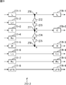
- FIG. 30 is a diagram illustrating a configuration example of the downmix unit 213-1 in FIG.
- the downmix unit 213-1 includes an input terminal 241-1 through an input terminal 241-7, a multiplier 242 through a multiplier 244, an adder 245, an adder 246, and an output terminal 247-1 through an output terminal 247-6. Is done.
- the audio data of the L, R, C, Ls, Rs, Cs, and LFE channels is supplied from the switching unit 212 to the input terminals 241-1 to 241-7, respectively.
- the input terminals 241-1 through 241-3 supply the audio data supplied from the switching unit 212 to the switching unit 214 as they are via the output terminals 247-1 through 247-3. That is, the audio data of each of the L, R, and C channels supplied to the downmix unit 213-1 is directly output to the subsequent stage as audio data of each of the L, R, and C channels after downmixing.
- the input terminals 241-4 to 241-6 supply the audio data supplied from the switching unit 212 to the multipliers 242 to 244.
- the multiplier 242 multiplies the audio data supplied from the input terminal 241-4 by a downmix coefficient and supplies the result to the adder 245.
- the multiplication unit 243 multiplies the audio data supplied from the input terminal 241-5 by a coefficient for downmixing, and supplies the result to the addition unit 246.
- the multiplication unit 244 multiplies the audio data supplied from the input terminal 241-6 by a coefficient for downmixing, and supplies the result to the addition unit 245 and the addition unit 246.
- the adder 245 adds the audio data supplied from the multiplier 242 and the audio data supplied from the multiplier 244 and supplies the result to the output terminal 247-4.
- the output terminal 247-4 supplies the audio data supplied from the adding unit 245 to the switching unit 214 as audio data of the Ls channel after downmixing.
- the adder 246 adds the audio data supplied from the multiplier 243 and the audio data supplied from the multiplier 244 and supplies the result to the output terminal 247-5.
- the output terminal 247-5 supplies the audio data supplied from the adding unit 246 to the switching unit 214 as audio data of the Rs channel after downmixing.
- the input terminal 241-7 supplies the audio data supplied from the switching unit 212 to the switching unit 214 as it is via the output terminal 247-6. That is, the audio data of the LFE channel supplied to the downmix unit 213-1 is directly output to the subsequent stage as audio data of the LFE channel after downmixing.
- FIG. 31 is a diagram illustrating a configuration example of the downmix unit 213-2 of FIG.
- the downmix unit 213-2 includes an input terminal 271-1 through an input terminal 271-8, a multiplier 272 through a multiplier 275, an adder 276, an adder 277, an adder 278, and an output terminal 279-1 through an output terminal 279. It consists of -6.
- the audio data of the L, Lc, C, Rc, R, Ls, Rs, and LFE channels is supplied from the switching unit 212 to the input terminals 271-1 to 271-8, respectively.
- the input terminals 271-1 to 271-5 convert the audio data supplied from the switching unit 212 to an adder 276, a multiplier 272 and a multiplier 273, an adder 277, a multiplier 274 and a multiplier 275, and It supplies to the addition part 278.
- the multiplying unit 272 and the multiplying unit 273 multiply the audio data supplied from the input terminal 271-2 by a coefficient for downmixing, and supplies the result to the adding unit 276 and the adding unit 277. Further, the multiplication unit 274 and the multiplication unit 275 multiply the audio data supplied from the input terminal 271-4 by a coefficient for downmixing, and supplies the result to the addition unit 277 and the addition unit 278.
- the adder 276 adds the audio data supplied from the input terminal 271-1 and the audio data supplied from the multiplier 272 and supplies the result to the output terminal 279-1.
- the output terminal 279-1 supplies the audio data supplied from the adding unit 276 to the switching unit 214 as L-channel audio data after downmixing.
- the adder 277 adds the audio data supplied from the input terminal 271-3, the audio data supplied from the multiplier 273, and the audio data supplied from the multiplier 274, and supplies the result to the output terminal 279-2. .
- the output terminal 279-2 supplies the audio data supplied from the adding unit 277 to the switching unit 214 as C-channel audio data after downmixing.
- the adder 278 adds the audio data supplied from the input terminal 271-5 and the audio data supplied from the multiplier 275, and supplies the result to the output terminal 279-3.
- the output terminal 279-3 supplies the audio data supplied from the addition unit 278 to the switching unit 214 as R-channel audio data after downmixing.
- the input terminals 271-6 to 271-8 supply the audio data supplied from the switching unit 212 to the switching unit 214 as they are via the output terminals 279-4 to 279-6. That is, the audio data of each channel of Ls, Rs, and LFE supplied to the downmix unit 213-2 is directly output as audio data of each channel of Ls, Rs, and LFE after downmixing.
- FIG. 32 is a diagram illustrating a configuration example of the downmix unit 213-3 in FIG.
- the downmix unit 213-3 includes an input terminal 301-1 through an input terminal 301-8, a multiplier 302 through a multiplier 305, an adder 306, an adder 307, and an output terminal 308-1 through an output terminal 308-6. Is done.
- the audio data of each channel of L, R, C, Ls, Rs, Lrs, Rrs, and LFE is supplied from the switching unit 212 to the input terminal 301-1 to the input terminal 301-8, respectively.
- the input terminals 301-1 through 301-3 supply the audio data supplied from the switching unit 212 to the switching unit 214 as they are via the output terminals 308-1 through 308-3. That is, the audio data of each of the L, R, and C channels supplied to the downmix unit 213-3 is directly output to the subsequent stage as audio data of each of the L, R, and C channels after downmixing.
- the input terminals 301-4 through 301-7 supply the audio data supplied from the switching unit 212 to the multipliers 302 through 305.
- the multipliers 302 to 305 multiply the audio data supplied from the input terminals 301-4 to 301-7 by a coefficient for downmixing, and adder 306, adder 307, adder 306, And supplied to the adder 307.
- the adder 306 adds the audio data supplied from the multiplier 302 and the audio data supplied from the multiplier 304 and supplies the result to the output terminal 308-4.
- the output terminal 308-4 supplies the audio data supplied from the adding unit 306 to the switching unit 214 as the audio data of the Ls channel after downmixing.
- the adder 307 adds the audio data supplied from the multiplier 303 and the audio data supplied from the multiplier 305, and supplies the result to the output terminal 308-5.
- the output terminal 308-5 supplies the audio data supplied from the addition unit 307 to the switching unit 214 as audio data of the Rs channel after downmixing.
- the input terminal 301-8 supplies the audio data supplied from the switching unit 212 to the switching unit 214 as it is via the output terminal 308-6. That is, the audio data of the LFE channel supplied to the downmix unit 213-3 is directly output to the subsequent stage as audio data of the LFE channel after downmixing.
- FIG. 33 is a diagram illustrating a configuration example of the downmix unit 213-4 of FIG.
- the downmix unit 213-4 includes an input terminal 331-1 through an input terminal 331-8, a multiplier 332 through a multiplier 335, an adder 336, an adder 337, and an output terminal 338-1 through an output terminal 338-6. Is done.
- the audio data of the L, R, C, Ls, Rs, Lvh, Rvh, and LFE channels is supplied from the switching unit 212 to the input terminal 331-1 to the input terminal 331-8, respectively.
- the input terminal 331-1 and the input terminal 331-2 supply the audio data supplied from the switching unit 212 to the multiplication unit 332 and the multiplication unit 333, respectively. Further, the input terminal 331-6 and the input terminal 331-7 supply the audio data supplied from the switching unit 212 to the multiplication unit 334 and the multiplication unit 335, respectively.
- the multipliers 332 to 335 multiply the audio data supplied from the input terminal 331-1, the input terminal 331-2, the input terminal 331-6, and the input terminal 331-7 by a coefficient for downmixing. , Adder 336, adder 337, adder 336, and adder 337.
- the adder 336 adds the audio data supplied from the multiplier 332 and the audio data supplied from the multiplier 334, and supplies the result to the output terminal 338-1.
- the output terminal 338-1 supplies the audio data supplied from the adding unit 336 to the switching unit 214 as L-channel audio data after downmixing.
- the adder 337 adds the audio data supplied from the multiplier 333 and the audio data supplied from the multiplier 335, and supplies the result to the output terminal 338-2.
- the output terminal 338-2 supplies the audio data supplied from the adding unit 337 to the switching unit 214 as R-channel audio data after downmixing.
- the input terminal 331-3 through the input terminal 331-5 and the input terminal 331-8 send the audio data supplied from the switching unit 212 to the output terminal 338-3 through the output terminal 338-5 and the output terminal 338-6. Then, the data is supplied to the switching unit 214 as it is. That is, the audio data of each channel of C, Ls, Rs, and LFE supplied to the downmix unit 213-4 is directly output as audio data of each channel of C, Ls, Rs, and LFE after downmixing.
- the input terminal 331-3 through the input terminal 331-5 and the input terminal 331-8 send the audio data supplied from the switching unit 212 to the output terminal 338-3 through the output terminal 338-5 and the output terminal 338-6. Then, the data is supplied to the switching unit 214 as it is. That is, the audio data of each channel of C, Ls, Rs, and LFE supplied to the downmix unit 213-4 is directly output as audio data of each channel of C, Ls, Rs, and LFE after downmixing.
- FIG. 34 is a diagram illustrating a configuration example of the downmix unit 217-1 in FIG.
- the downmix unit 217-1 includes an input terminal 361-1 through an input terminal 361-6, a multiplier 362 through a multiplier 365, an adder 366 through an adder 371, an output terminal 372-1, and an output terminal 372-2. Is done.
- the audio data of the L, R, C, Ls, Rs, and LFE channels is supplied from the switching unit 216 to the input terminals 361-1 to 361-6, respectively.
- the input terminals 361-1 through 361-6 supply the audio data supplied from the switching unit 216 to the adder 366, adder 369, and multipliers 362 through 365, respectively.
- the multipliers 362 to 365 multiply the audio data supplied from the input terminals 361-3 to 361-6 by a coefficient for downmixing, and adder 366, adder 369, adder 367, The data is supplied to the adder 370, the adder 368, and the adder 371.
- the adder 366 adds the audio data supplied from the input terminal 361-1 and the audio data supplied from the multiplier 362 and supplies the result to the adder 367.
- the adder 367 adds the audio data supplied from the adder 366 and the audio data supplied from the multiplier 363 and supplies the result to the adder 368.
- the adder 368 adds the audio data supplied from the adder 367 and the audio data supplied from the multiplier 365 and supplies the result to the output terminal 372-1.
- the output terminal 372-1 supplies the audio data supplied from the adding unit 368 to the gain adjusting unit 218 as L-channel audio data after downmixing.
- the adder 369 adds the audio data supplied from the input terminal 361-2 and the audio data supplied from the multiplier 362 and supplies the result to the adder 370.
- the adder 370 adds the audio data supplied from the adder 369 and the audio data supplied from the multiplier 364 and supplies the result to the adder 371.
- the adder 371 adds the audio data supplied from the adder 370 and the audio data supplied from the multiplier 365 and supplies the result to the output terminal 372-2.
- the output terminal 372-2 supplies the audio data supplied from the adding unit 371 to the gain adjusting unit 218 as R channel audio data after downmixing.
- FIG. 35 is a diagram illustrating a configuration example of the downmix unit 217-2 of FIG.
- the downmix unit 217-2 includes an input terminal 401-1 through an input terminal 401-6, a multiplier unit 402 through a multiplier unit 405, an adder unit 406, a subtractor unit 407, a subtractor unit 408, an adder unit 409 through an adder unit 413, and an output terminal. 414-1 and an output terminal 414-2.
- the audio data of the L, R, C, Ls, Rs, and LFE channels is supplied from the switching unit 216 to the input terminal 401-1 to the input terminal 401-6, respectively.
- the input terminals 401-1 through 401-6 supply the audio data supplied from the switching unit 216 to the adder 406, the adder 410, and the multipliers 402 through 405, respectively.
- the multipliers 402 to 405 multiply the audio data supplied from the input terminals 401-3 to 401-6 by a coefficient for downmixing, adder 406 and adder 410, subtractor 407 and The data is supplied to the adder 411, the subtractor 408 and the adder 412, and the adder 409 and the adder 413.
- the addition unit 406 adds the audio data supplied from the input terminal 401-1 and the audio data supplied from the multiplication unit 402 and supplies the result to the subtraction unit 407.
- the subtraction unit 407 subtracts the audio data supplied from the multiplication unit 403 from the audio data supplied from the addition unit 406 and supplies the result to the subtraction unit 408.
- the subtraction unit 408 subtracts the audio data supplied from the multiplication unit 404 from the audio data supplied from the subtraction unit 407 and supplies the subtraction unit 408 to the addition unit 409.
- the adder 409 adds the audio data supplied from the subtractor 408 and the audio data supplied from the multiplier 405 and supplies the result to the output terminal 414-1.
- the output terminal 414-1 supplies the audio data supplied from the adding unit 409 to the gain adjusting unit 218 as the audio data of the L channel after downmixing.
- the adder 410 adds the audio data supplied from the input terminal 401-2 and the audio data supplied from the multiplier 402, and supplies the result to the adder 411.
- the adder 411 adds the audio data supplied from the adder 410 and the audio data supplied from the multiplier 403 and supplies the result to the adder 412.
- the adder 412 adds the audio data supplied from the adder 411 and the audio data supplied from the multiplier 404 and supplies the result to the adder 413.
- the adder 413 adds the audio data supplied from the adder 412 and the audio data supplied from the multiplier 405 and supplies the result to the output terminal 414-2.
- the output terminal 414-2 supplies the audio data supplied from the adding unit 413 to the gain adjusting unit 218 as R channel audio data after downmixing.
- step S111 the separation unit 61 acquires the encoded bitstream output from the encoding device 91 and the downmix format parameter.
- the downmix format parameter is acquired from an information processing device provided with a decoding device.
- the separation unit 61 supplies the acquired downmix format parameters to the switching unit 151 and the downmix processing unit 152, and acquires the output file name of the audio data as necessary and uses it appropriately.
- step S112 the separation unit 61 unpacks the encoded bit stream, and supplies each element obtained as a result to the decoding unit 62.
- the PCE decoding unit 161 decodes the PCE supplied from the separation unit 61. For example, the PCE decoding unit 161 reads “height_extension_element”, which is an extension area, from the PCE comment area, or reads information about speaker arrangement from the PCE.
- information about the speaker arrangement for example, the number of channels reproduced by the speakers arranged in front, side, and rear of the user, and any channel such as C, L, and R in which each audio data is provided. Information indicating whether the data is the same data is read out.
- step S114 the DSE decoding unit 162 decodes the DSE supplied from the separation unit 61. For example, the DSE decoding unit 162 reads “MPEG4 ancillary data” from the DSE, and further reads necessary information from “MPEG4 ancillary data”.
- the downmix information decoding unit 174 of the DSE decoding unit 162 uses “center_mix_level_value” and “surround_mix_level_value” as information for specifying a coefficient used for downmixing from “downmixing_levels_MPEG4 ()” illustrated in FIG. This is read and supplied to the downmix processing unit 152.
- step S115 the audio element decoding unit 163 decodes the audio data stored in the SCE, CPE, and LFE elements supplied from the separation unit 61. Thereby, PCM data of each channel is obtained as audio data.
- the channel of the decoded audio data that is, the arrangement position on the horizontal plane can be specified by the element such as SCE in which the audio data is stored and the information on the speaker arrangement obtained by the DSE decoding.
- speaker arrangement information which is information relating to the height of the speaker arrangement, has not been read out, so the height (layer) of each channel is not specified.
- the audio element decoding unit 163 supplies the audio data obtained by the decoding to the switching unit 151.
- step S116 the switching unit 151 determines whether or not to perform the audio data downmix based on the downmix format parameter supplied from the separation unit 61. For example, if the downmix format parameter indicates that downmixing is not performed, it is determined that downmixing is not performed.
- step S116 When it is determined in step S116 that the downmix is not performed, the switching unit 151 supplies the audio data supplied from the decoding unit 62 to the rearrangement processing unit 181, and the process proceeds to step S117.
- step S117 the decoding device 141 performs a rearrangement process to rearrange and output the audio data according to the speaker arrangement.
- the decoding process ends. Details of the rearrangement process will be described later.
- step S116 when it is determined in step S116 that downmixing is to be performed, the switching unit 151 supplies the audio data supplied from the decoding unit 62 to the switching unit 211 of the downmix processing unit 152, and the processing is performed in step S118. Proceed to
- step S118 the decoding device 141 performs a downmix process, downmixes each audio data into audio data of the number of channels indicated by the downmix format parameter, and outputs the audio data.
- the decoding process ends. Details of the downmix process will be described later.
- the decoding device 141 decodes the encoded bit stream and outputs audio data.
- step S142 the synchronization word detection unit 171 reads data from the PCE comment area by a predetermined amount of synchronization word data. For example, in the example of FIG. 4, since the synchronization word “PCE_HEIGHT_EXTENSION_SYNC” is 8 bits, that is, 1 byte, data of 1 byte is read from the head of the comment area of the PCE.
- step S143 the PCE decoding unit 161 determines whether or not the data read in step S142 matches the synchronization word. That is, it is determined whether or not the read data is a synchronization word.
- step S144 the synchronization word detection unit 171 decreases the value of the parameter cmt_byte by the read data amount. In this case, the value of the parameter cmt_byte is decreased by 1 byte.
- step S145 the synchronization word detection unit 171 determines whether or not the parameter cmt_byte> 0. That is, it is determined whether or not the parameter cmt_byte is larger than 0, in other words, whether or not all data in the comment area has been read out.
- step S145 If it is determined in step S145 that the parameter cmt_byte> 0, all data has not yet been read from the comment area, so the process returns to step S142 and the above-described process is repeated. That is, the data corresponding to the data amount of the synchronization word following the data read so far in the comment area is read out and collated with the synchronization word.
- step S145 if it is determined in step S145 that the parameter cmt_byte> 0 is not satisfied, the process proceeds to step S146.
- the process proceeds to step S146 in this way when all the data in the comment area has been read, but no synchronization word has been detected from the comment area.
- step S146 the PCE decoding unit 161 supplies the information to that effect to the rearrangement processing unit 181 assuming that there is no speaker arrangement information, and the process proceeds to step S164.
- “height_extension_element” it is possible to more easily and reliably specify whether or not the information included in the comment area is the speaker arrangement information by arranging the synchronization word immediately before the speaker arrangement information. It becomes like this.
- step S143 If it is determined in step S143 that the data read from the comment area matches the synchronization word, the synchronization word has been detected. Therefore, the process proceeds to step S147 to read the speaker arrangement information immediately following the synchronization word. Proceed to
- step S147 the PCE decoding unit 161 sets the value of the parameter num_fr_elem for reading the speaker arrangement information of the audio data reproduced by the speaker arranged in front of the user as the number of elements belonging to the front.
- the number of elements belonging to the front is the number of audio data (number of channels) reproduced by a speaker arranged in front of the user, and this number of elements is stored in the PCE. Accordingly, the value of the parameter num_fr_elem is the number of pieces of speaker arrangement information of audio data to be read from “height_extension_element” and reproduced by a speaker arranged in front.
- step S148 the PCE decoding unit 161 determines whether or not the parameter num_fr_elem> 0.
- step S148 If it is determined in step S148 that the parameter num_fr_elem is greater than 0, there is still speaker arrangement information to be read out, and the process proceeds to step S149.
- step S149 the PCE decoding unit 161 reads speaker arrangement information for one element arranged subsequent to the synchronization word in the comment area.
- speaker arrangement information for one element arranged subsequent to the synchronization word in the comment area.
- one speaker arrangement information is 2 bits
- 2-bit data arranged immediately after the data read so far in the comment area is read as one speaker arrangement information. It is.
- step S150 the PCE decoding unit 161 reads one piece of speaker arrangement information, and thus decrements the value of the parameter num_fr_elem by one.
- the process returns to step S148 and the above-described process is repeated. That is, the next speaker arrangement information is read out.
- step S148 If it is determined in step S148 that the parameter num_fr_elem> 0 is not satisfied, all the speaker arrangement information of the front element has been read, and the process proceeds to step S151.
- step S151 the PCE decoding unit 161 sets the value of the parameter num_side_elem for reading the speaker arrangement information of the audio data reproduced by the speaker arranged on the side as viewed from the user as the number of elements belonging to the side.
- the number of elements belonging to the side is the number of audio data reproduced by a speaker arranged on the side of the user, and this number of elements is stored in the PCE.
- step S152 the PCE decoding unit 161 determines whether or not the parameter num_side_elem> 0.
- step S153 the PCE decoding unit 161 stores speaker arrangement information for one element arranged subsequent to the data read so far in the comment area. read out.
- the speaker arrangement information read in step S153 is the speaker arrangement information of the channel on the side of the user, that is, “side_element_height_info [i]”.
- step S154 the PCE decoding unit 161 decrements the value of the parameter num_side_elem by 1.
- the process returns to step S152 and the above-described process is repeated.
- step S152 If it is determined in step S152 that the parameter num_side_elem> 0 is not satisfied, all the speaker arrangement information of the side elements has been read, and the process proceeds to step S155.
- step S155 the PCE decoding unit 161 sets the value of the parameter num_back_elem for reading the speaker arrangement information of the audio data reproduced by the speaker arranged behind when viewed from the user as the number of elements belonging to the rear.
- the number of elements belonging to the rear is the number of audio data reproduced by a speaker arranged behind the user, and this number of elements is stored in the PCE.
- step S156 the PCE decoding unit 161 determines whether or not the parameter num_back_elem> 0.
- step S157 the PCE decoding unit 161 stores speaker arrangement information for one element arranged subsequent to the data read so far in the comment area. read out.
- the speaker arrangement information read in step S157 is the speaker arrangement information of the channel behind the user, that is, “back_element_height_info [i]”.
- step S158 the PCE decoding unit 161 decrements the value of the parameter num_back_elem by 1.
- the process returns to step S156 and the above-described process is repeated.
- step S156 If it is determined in step S156 that the parameter num_back_elem> 0 is not satisfied, all the speaker arrangement information of the rear element has been read, and the process proceeds to step S159.
- step S159 the identification information calculation unit 172 performs byte alignment.
- the identification information calculation unit 172 causes the data amount of information read from “PCE_HEIGHT_EXTENSION_SYNC” to “byte_alignment ()” in “height_extension_element” to be an 8-bit integer multiple data amount.
- predetermined data is added immediately after such information. That is, byte alignment is performed so that the total data amount of the read synchronization word, speaker arrangement information, and added data is an integer multiple of 8 bits.
- the number of channels of audio data that is, the number of speaker arrangement information included in the encoded bitstream is a number within a predetermined range. Therefore, the data obtained by byte alignment, that is, one data (hereinafter also referred to as alignment data) composed of the synchronization word, the speaker arrangement information, and the added data is always made into a predetermined amount of data. Yes.
- the amount of alignment data is always a predetermined amount regardless of the number of speaker arrangement information included in the “height_extension_element”, that is, the number of channels of audio data. Therefore, when the alignment data is not a predetermined amount of data when the alignment data is generated, the PCE decoding unit 161 does not read the speaker arrangement information read so far, that is, correct speaker arrangement information. Suppose it is invalid.
- step S160 the identification information calculation unit 172 reads the identification information following “byte_alignment ()” read in step S159, that is, the information stored in “height_info_crc_check” in “height_extension_element”.
- a CRC check code is read as identification information.
- step S161 the identification information calculation unit 172 calculates identification information based on the alignment data obtained in step S159. For example, a CRC check code is calculated as identification information.
- step S162 the PCE decoding unit 161 determines whether or not the identification information read in step S160 matches the identification information calculated in step S161.
- the PCE decoding unit 161 determines that the identification information does not match in step S162 without performing the processing in steps S160 and S161.
- step S163 If it is determined in step S162 that the identification information does not match, in step S163, the PCE decoding unit 161 invalidates the read speaker arrangement information, and sorts the information to that effect into the rearrangement processing unit 181 and the downmix processing unit 152. To supply. Then, the process proceeds to step S164.
- step S164 the rearrangement processing unit 181 outputs the audio data supplied from the switching unit 151 in a predetermined speaker arrangement.
- the rearrangement processing unit 181 determines the speaker arrangement of each audio data based on the information about the speaker arrangement read from the PCE supplied from the PCE decoding unit 161.
- the reference destination of the information used by the reordering processing unit 181 when determining the speaker arrangement depends on the service and application using the audio data, and is determined in advance according to the number of channels of the audio data.
- step S164 When the process of step S164 is performed, the rearrangement process ends, and thus the process of step S117 of FIG. 36 is also ended, so that the decoding process ends.
- step S165 the PCE decoding unit 161 validates the read speaker arrangement information, rearranges the speaker arrangement information, and the rearrangement processing unit 181 and the downmix processing unit. 152. At this time, the PCE decoding unit 161 also supplies information about the speaker arrangement read from the PCE to the rearrangement processing unit 181 and the downmix processing unit 152.
- step S166 the rearrangement processing unit 181 outputs the audio data supplied from the switching unit 151 with the speaker arrangement determined from the speaker arrangement information supplied from the PCE decoding unit 161 and the like. That is, the audio data of each channel is rearranged in the order determined by the speaker arrangement information or the like and output to the subsequent stage.
- the rearrangement process ends, and thereby the process of step S117 of FIG.
- the decoding device 141 reads the speaker arrangement information by collating the synchronization word and the CRC check code from the comment area of the PCE, and outputs the decoded audio data with the arrangement according to the speaker arrangement information. To do.
- the speaker arrangement information can be read more reliably from the comment area in which other text information or the like may be stored. That is, the speaker arrangement information and other information can be more reliably identified.
- the speaker arrangement information is distinguished from other information by the three elements of synchronization word matching, CRC check code matching, and alignment data amount matching. False detection can be suppressed. In this way, by suppressing erroneous detection of the speaker arrangement information, it becomes possible to reproduce audio data with the correct speaker arrangement, and it is possible to obtain high-quality sound with a more realistic feeling.
- step S191 the extension detection unit 173 of the DSE decoding unit 162 reads “ancillary_data_extension_status” from “ancillary_data_status ()” in “MPEG4_ancillary_data ()” of the DSE.
- step S192 the extension detection unit 173 determines whether or not the read “ancillary_data_extension_status” is 1.
- step S192 when “ancillary_data_extension_status” is not 1, that is, it is determined to be 0, in step S193, the downmix processing unit 152 performs a downmix of the audio data by a predetermined method.
- the downmix processing unit 152 downmixes the audio data from the switching unit 151 using the coefficients determined by “center_mix_level_value” and “surround_mix_level_value” supplied from the downmix information decoding unit 174 and supplies the audio data to the output unit 63. .
- the downmix process may be performed in any way.
- step S194 the output unit 63 outputs the audio data supplied from the downmix processing unit 152 to the subsequent stage as it is, and the downmix processing ends. Thereby, since the process of step S118 of FIG. 36 is completed, the decoding process is also terminated.
- step S192 determines whether “ancillary_data_extension_status” is 1, the process proceeds to step S195.
- step S 195 the downmix information decoding unit 174 reads the information in “ext_downmixing_levels ()” of “MPEG4_ext_ancillary_data ()” illustrated in FIG. 11 and supplies the information to the downmix processing unit 152.
- “dmix_a_idx” and “dmix_b_idx” in FIG. 13 are read.
- step S 196 the downmix information decoding unit 174 reads the information in “ext_downmixing_global_gains ()” of “MPEG4_ext_ancillary_data ()” and supplies it to the downmix processing unit 152.
- the information shown in FIG. 15, that is, “dmx_gain_5_sign”, “dmx_gain_5_idx”, “dmx_gain_2_sign”, and “dmx_gain_2_idx” are read out.
- step S 197 the downmix information decoding unit 174 reads the information in “ext_downmixing_lfe_level ()” of “MPEG4_ext_ancillary_data ()” and supplies it to the downmix processing unit 152. Thereby, for example, “dmix_lfe_idx” illustrated in FIG. 16 is read.
- the downmix information decoding unit 174 reads “ext_downmixing_lfe_level_status” shown in FIG. 12, and reads “dmix_lfe_idx” according to the value of “ext_downmixing_lfe_level_status”.
- “dmix_lfe_idx” is not read when “ext_downmixing_lfe_level_status” included in “MPEG4_ext_ancillary_data ()” is 0.
- the audio data of the LFE channel is not used in the downmix from 5.1 channel to 2 channels of audio data described below. That is, the coefficient multiplied to the audio data of the LFE channel is set to 0.
- step S198 the downmix information decoding unit 174 reads the information stored in “pseudo_surround_enable” from “bs_info ()” of “MPEG4PEGancillary data” shown in FIG. 7 and supplies the information to the downmix processing unit 152. To do.
- step S199 the downmix processing unit 152 determines whether the audio data is a 2-channel output based on the downmix format parameters supplied from the separation unit 61.
- the downmix format parameter indicates that a downmix from 7.1 channel or 6.1 channel to 2 channels or a downmix from 5.1 channel to 2 channels is performed, it is determined that the output is 2 channels. .
- step S199 If it is determined in step S199 that the output is 2 channels, the process proceeds to step S200. In this case, the output destination of the switching unit 214 is switched to the switching unit 216.
- step S200 the downmix processing unit 152 determines whether the input of audio data is 5.1 channel based on the downmix format parameter from the separation unit 61. For example, if the downmix format parameter indicates that a downmix from 5.1 channels to 2 channels is to be performed, it is determined that the input is 5.1 channels.
- step S200 If it is determined in step S200 that the input is not 5.1 channel, the process proceeds to step S201, and downmix from 7.1 channel or 6.1 channel to 2 channel is performed.
- the switching unit 211 supplies the audio data supplied from the switching unit 151 to the switching unit 212. Further, the switching unit 212 converts the audio data supplied from the switching unit 211 to any one of the downmix unit 213-1 to the downmix unit 213-4 based on the information regarding the speaker arrangement supplied from the PCE decoding unit 161. To supply. For example, when the audio data is 6.1 channel data, the audio data of each channel is supplied to the downmix unit 213-1.
- step S201 the downmix unit 213 performs the downmix process to the 5.1 channel based on “dmix_a_idx” and “dmix_b_idx” read from “ext_downmixing_levels ()” supplied from the downmix information decoding unit 174. Do.
- the downmix unit 213-1 when audio data is supplied to the downmix unit 213-1, the downmix unit 213-1 refers to the table shown in FIG. 19 and constants determined for the values of “dmix_a_idx” and “dmix_b_idx” Are constants g1 and g2, respectively. Then, the downmix unit 213-1 uses the constants g1 and g2 as coefficients used in the multiplication unit 242, the multiplication unit 243, and the multiplication unit 244, respectively, thereby performing the calculation of Expression (6), and the 5.1 channel audio Data is generated and supplied to the switching unit 214.
- the downmix unit 213-2 sets constants determined for the values of “dmix_a_idx” and “dmix_b_idx” as constants e1 and e2, respectively. Then, the downmix unit 213-2 performs the calculation of Expression (4) by using the constants e1 and e2 as coefficients used in the multiplication unit 273 and the multiplication unit 274, and the multiplication unit 272 and the multiplication unit 275, respectively.
- the supplied 5.1-channel audio data is supplied to the switching unit 214.
- the downmix unit 213-3 sets constants determined for the values of “dmix_a_idx” and “dmix_b_idx” as constants d1 and d2, respectively.
- the downmix unit 213-3 performs the calculation of Expression (3) by using the constants d1 and d2 as coefficients used in the multiplier 302 and the multiplier 303, and the multiplier 304 and the multiplier 305, respectively.
- the audio data thus received is supplied to the switching unit 214.
- the downmix unit 213-4 sets constants determined for the values of “dmix_a_idx” and “dmix_b_idx” as constants f1 and f2, respectively. Then, the downmix unit 213-4 performs the calculation of Expression (5) by using the constants f1 and f2 as coefficients used in the multiplication unit 332 and the multiplication unit 333, and the multiplication unit 334 and the multiplication unit 335, respectively.
- the audio data thus received is supplied to the switching unit 214.
- the switching unit 214 supplies the audio data from the downmix unit 213 to the switching unit 216. Further, the switching unit 216 supplies the audio data from the switching unit 214 to the downmix unit 217-1 or the downmix unit 217-2 according to the value of “pseudo_surround_enable” supplied from the downmix information decoding unit 174. To do.
- the audio data is supplied to the downmix unit 217-1, and when the value of “pseudo_surround_enable” is 1, the audio data is supplied to the downmix unit 217-2. .
- step S202 the downmix unit 217 performs the downmix processing of the audio data supplied from the switching unit 216 into two channels based on the information regarding the downmix supplied from the downmix information decoding unit 174. That is, based on the information in “downmixing_levels_MPEG4 ()” and the information in “ext_mixdownmixing_lfe_level ()”, the downmix processing to two channels is performed.
- the downmix unit 217-1 when audio data is supplied to the downmix unit 217-1, the downmix unit 217-1 refers to the table of FIG. 19 and sets constants determined for the values of “center_mix_level_value” and “surround_mix_level_value”, respectively. Let constants a and b. Further, the downmix unit 217-1 refers to the table shown in FIG. 18 and sets a constant determined for the value of “dmix_lfe_idx” as a constant c.
- the downmix unit 217-1 performs the calculation of the expression (1) by using the constants a, b, and c as coefficients used in the multiplication unit 363, the multiplication unit 364, the multiplication unit 362, and the multiplication unit 365.
- the two-channel audio data is supplied to the gain adjusting unit 218.
- the downmix unit 217-2 determines constants a, b, and c in the same manner as in the downmix unit 217-1. Then, the downmix unit 217-2 performs the calculation of Expression (2) by using the constants a, b, and c as coefficients used in the multiplication unit 403, the multiplication unit 404, the multiplication unit 402, and the multiplication unit 405. The audio data thus received is supplied to the gain adjustment unit 218.
- step S203 the gain adjustment unit 218 performs gain adjustment of the audio data from the downmix unit 217 based on the information read from “ext_downmixing_global_gains ()” supplied from the downmix information decoding unit 174.
- the gain adjustment unit 218 calculates Expression (11) based on “dmx_gain_5_sign”, “dmx_gain_5_idx”, “dmx_gain_2_sign”, and “dmx_gain_2_idx” read from “ext_downmixing_global_gains ()”, and gain value dmx_gain_7to2 Is calculated. Then, the gain adjusting unit 218 multiplies the audio data of each channel by the gain value dmx_gain_7to2 and supplies the result to the output unit 63.
- step S204 the output unit 63 outputs the audio data supplied from the gain adjusting unit 218 to the subsequent stage as it is, and the downmix process ends. Thereby, since the process of step S118 of FIG. 36 is completed, the decoding process is also terminated.
- audio data is output from the output unit 63
- audio data is output from the rearrangement processing unit 181 and a case where audio data from the downmix processing unit 152 is output as it is.
- it can be determined in advance which of the two types of output of these audio data is used.
- step S200 If it is determined in step S200 that the input is 5.1 channel, the process proceeds to step S205, and downmixing from 5.1 channel to 2 channels is performed.
- the switching unit 211 supplies the audio data supplied from the switching unit 151 to the switching unit 216. Also, the switching unit 216 supplies the audio data from the switching unit 211 to the downmix unit 217-1 or the downmix unit 217-2 according to the value of “pseudo_surround_enable” supplied from the downmix information decoding unit 174. To do.
- step S205 the downmix unit 217 performs the downmix processing of the audio data supplied from the switching unit 216 into two channels based on the information about the downmix supplied from the downmix information decoding unit 174.
- step S205 processing similar to that in step S202 is performed.
- step S206 the gain adjustment unit 218 performs gain adjustment of the audio data from the downmix unit 217 based on the information read from “ext_downmixing_global_gains ()” supplied from the downmix information decoding unit 174.
- the gain adjustment unit 218 calculates Expression (9) based on “dmx_gain_2_sign” and “dmx_gain_2_idx” read from “ext_downmixing_global_gains ()”, and outputs the audio data obtained as a result to the output unit 63. Supply.
- step S207 the output unit 63 outputs the audio data supplied from the gain adjustment unit 218 to the subsequent stage as it is, and the downmix process ends. Thereby, since the process of step S118 of FIG. 36 is completed, the decoding process is also terminated.
- step S199 determines whether the output is not 2 channels, that is, 5.1 channel output. If it is determined in step S199 that the output is not 2 channels, that is, 5.1 channel output, the process proceeds to step S208, and downmixing from 7.1 channel or 6.1 channel to 5.1 channel is performed.
- the switching unit 211 supplies the audio data supplied from the switching unit 151 to the switching unit 212. Further, the switching unit 212 converts the audio data supplied from the switching unit 211 to any one of the downmix unit 213-1 to the downmix unit 213-4 based on the information regarding the speaker arrangement supplied from the PCE decoding unit 161. To supply. Further, the output destination of the switching unit 214 is the gain adjusting unit 215.
- step S208 the downmix unit 213 performs the downmix process to the 5.1 channel based on “dmix_a_idx” and “dmix_b_idx” read from “ext_downmixing_levels ()” supplied from the downmix information decoding unit 174. Do. In step S208, processing similar to that in step S201 is performed.
- the switching unit 214 supplies the supplied audio data to the gain adjusting unit 215.
- step S209 the gain adjustment unit 215 adjusts the gain of the audio data from the switching unit 214 based on the information read from “ext_downmixing_global_gains ()” supplied from the downmix information decoding unit 174.
- the gain adjustment unit 215 calculates Expression (7) based on “dmx_gain_5_sign” and “dmx_gain_5_idx” read from “ext_downmixing_global_gains ()”, and outputs the audio data obtained as a result to the output unit 63. Supply.
- step S210 the output unit 63 outputs the audio data supplied from the gain adjusting unit 215 to the subsequent stage as it is, and the downmix process ends. Thereby, since the process of step S118 of FIG. 36 is completed, the decoding process is also terminated.
- the decoding device 141 downmixes audio data based on information read from the encoded bitstream.
- extension information indicating whether extension information is included in the encoded bitstream is stored in “ancillary_data_extension_status”. Therefore, by referring to this information, it can be specified whether the extension information is included in the extension area. If such extended information can be obtained, the audio data can be downmixed with a higher degree of freedom, so that high-quality sound with a higher sense of presence can be obtained.
- the series of processes described above can be executed by hardware or can be executed by software.
- a program constituting the software is installed in the computer.
- the computer includes, for example, a general-purpose personal computer capable of executing various functions by installing a computer incorporated in dedicated hardware and various programs.
- FIG. 40 is a block diagram illustrating a configuration example of hardware of a computer that executes the above-described series of processes by a program.
- a CPU Central Processing Unit
- ROM Read Only Memory
- RAM Random Access Memory
- An input / output interface 505 is further connected to the bus 504.
- An input unit 506, an output unit 507, a recording unit 508, a communication unit 509, and a drive 510 are connected to the input / output interface 505.
- the input unit 506 includes a keyboard, a mouse, a microphone, an image sensor, and the like.
- the output unit 507 includes a display, a speaker, and the like.
- the recording unit 508 includes a hard disk, a nonvolatile memory, and the like.
- the communication unit 509 includes a network interface or the like.
- the drive 510 drives a removable medium 511 such as a magnetic disk, an optical disk, a magneto-optical disk, or a semiconductor memory.
- the CPU 501 loads the program recorded in the recording unit 508 to the RAM 503 via the input / output interface 505 and the bus 504 and executes the program, for example. Is performed.
- the program executed by the computer (CPU 501) can be provided by being recorded on the removable medium 511 as a package medium, for example.
- the program can be provided via a wired or wireless transmission medium such as a local area network, the Internet, or digital satellite broadcasting.
- the program can be installed in the recording unit 508 via the input / output interface 505 by attaching the removable medium 511 to the drive 510. Further, the program can be received by the communication unit 509 via a wired or wireless transmission medium and installed in the recording unit 508. In addition, the program can be installed in the ROM 502 or the recording unit 508 in advance.
- the program executed by the computer may be a program that is processed in time series in the order described in this specification, or in parallel or at a necessary timing such as when a call is made. It may be a program for processing.
- the present technology can take a cloud computing configuration in which one function is shared by a plurality of devices via a network and is jointly processed.
- each step described in the above flowchart can be executed by one device or can be shared by a plurality of devices.
- the plurality of processes included in the one step can be executed by being shared by a plurality of apparatuses in addition to being executed by one apparatus.
- the present technology can be configured as follows.
- a decoding unit for decoding the audio data included in the encoded bitstream A reading unit that reads sound source position information related to the height of the sound source of the audio data from an area where arbitrary data of the encoded bitstream can be stored; A decoding device comprising: an output unit that outputs the decoded audio data based on the sound source position information.
- the sound source position information is information indicating whether the height of the sound source is substantially the same as a user, above the user, or below the user.
- identification information for identifying the presence or absence of the sound source position information is stored, The decoding device according to [1] or [2], wherein the reading unit reads the sound source position information based on the identification information.
- first identification information determined in advance and second identification information calculated based on the sound source position information are stored as the identification information. 3].
- the first identification information included in the area in which the arbitrary data can be stored is predetermined specific information, and the read out from the area in which the arbitrary data can be stored If the second identification information matches the second identification information calculated based on the read sound source position information, the sound source position information is valid information.
- [8] Decode the audio data contained in the encoded bitstream, Read sound source position information related to the height of the sound source of the audio data from an area where arbitrary data of the encoded bitstream can be stored, A program for causing a computer to execute a process including a step of outputting the decoded audio data based on the sound source position information.
- the encoded sound source position information is stored in an area where arbitrary data can be stored, and the encoded audio data and a packing unit that generates an encoded bitstream including the sound source position information are provided.
- Encoding device Encoding device.
- the encoding apparatus according to [9], wherein the sound source position information is information indicating whether a height of the sound source is substantially the same as a user, above the user, or below the user.
- the sound source position information is information indicating whether a height of the sound source is substantially the same as a user, above the user, or below the user.
- identification information for identifying presence / absence of the sound source position information is stored together with the sound source position information in an area in which the arbitrary data can be stored.
- first identification information determined in advance and second identification information calculated based on the sound source position information are stored as the identification information.
- the encoding apparatus as described in.
- [15] Obtain sound source position information about the height of the sound source, Encoding audio data and the sound source position information; Storing the encoded sound source position information in an area where arbitrary data can be stored, and generating a coded bitstream including the encoded audio data and the sound source position information.
Landscapes
- Engineering & Computer Science (AREA)
- Physics & Mathematics (AREA)
- Signal Processing (AREA)
- Acoustics & Sound (AREA)
- Multimedia (AREA)
- Health & Medical Sciences (AREA)
- Human Computer Interaction (AREA)
- Audiology, Speech & Language Pathology (AREA)
- Computational Linguistics (AREA)
- Mathematical Physics (AREA)
- Theoretical Computer Science (AREA)
- Stereophonic System (AREA)
- Compression, Expansion, Code Conversion, And Decoders (AREA)
Abstract
Description
[本技術の概要について]
まず、本技術の概要について説明する。
(2) 特徴(1)の場合において、一般コメントと垂直方向のスピーカ配置情報を識別するために、符号化装置側で同期ワードとCRCチェックコードの2つの識別情報を符号化し、復号装置では、2つの識別情報の照合を行い、合致した場合にスピーカ配置情報を取得する。
(3) オーディオデータのダウンミックス情報をアンシラリデータ領域(DSE(data_stream_element))に記録する。
(4) 6.1チャンネルまたは7.1チャンネルから2チャンネルへのダウンミックスは、6.1チャンネルまたは7.1チャンネルから5.1チャンネルへのダウンミックスと、その後に行なわれる5.1チャンネルから2チャンネルへのダウンミックスとの2段階の処理とする。
次にオーディオデータが再生されるときの各スピーカの配置について説明する。
これらの各チャンネルのオーディオデータを符号化すると、例えば図3に示す符号化ビットストリームが得られる。すなわち、図3は、AACフレームの符号化ビットストリームのシンタックスを示している。
上述したように「PCE」の「comment_field_data」には「height_extension_element」が含まれており、これにより垂直方向のスピーカ配置情報によるマルチチャンネル再生が実現される。つまり、「Top layer」や「Middle layer」など各高さのレイヤに配置されたスピーカにより、より臨場感のある高品質な音声再生ができるようになる。
次に、「DSE」、つまり「data_stream_element()」の「data_stream_byte[]」に含まれるアンシラリデータ領域である「MPEG4 ancillary data」について説明する。この「MPEG4 ancillary data」によって、オーディオデータの6.1チャンネルまたは7.1チャンネルから、5.1チャンネルや2チャンネルへのダウンミックスDRC制御が可能となる。
また、図7に示した「bs_info()」のシンタックスにおける「pseudo_surround_enable」は、ダウンミックスの処理手順を示しており、その処理手順は図17に示す通りである。ここでは、「pseudo_surround_enable」が0である場合と1である場合の2通りの処理手順が示されている。
R’=R+C×b+Rs×a+LFE×c ・・・(1)
R’=R+C×b+a×(Ls+Rs)+LFE×c ・・・(2)
L’=L
R’=R
Ls’=Ls×d1+ Lrs×d2
Rs’=Rs×d1+ Rrs×d2
LFE’=LFE ・・・(3)
L’=L+Lc×e2
R’=R+Rc×e2
Ls’=Ls
Rs’=Rs
LFE’=LFE ・・・(4)
L’=L×f1+Lvh×f2
R’=R×f1+Rvh×f2
Ls’=Ls
Rs’=Rs
LFE’=LFE ・・・(5)
L’=L
R’=R
Ls’=Ls×g1+Cs×g2
Rs’=Rs×g1+Cs×g2
LFE’=LFE ・・・(6)
R’’=R’×dmx_gain5
C’’=C’×dmx_gain5
Ls’’=Ls’×dmx_gain5
Rs’’=Rs’×dmx_gain5
LFE’’=LFE’×dmx_gain5 ・・・(7)
dmx_gain5=10(-dmx_gain_5_idx/20) if dmx_gain_5_sign==0 ・・・(8)
R’’=R’×dmx_gain2 ・・・(9)
dmx_gain2=10(-dmx_gain_2_idx/20) if dmx_gain_2_sign==0 ・・・(10)
また、図7に示した「bs_info()」に含まれている「drc_presentation_mode」は図20に示すようになっている。すなわち、図20は、「drc_presentation_mode」のシンタックスを示す図である。
次に、本技術を適用した具体的な実施の形態について説明する。
さらに、図23のフローチャートを参照して、符号化装置11による符号化処理について説明する。
次に、符号化装置11から出力された符号化ビットストリームを受信して復号する復号装置について説明する。
続いて、図25のフローチャートを参照して、復号装置51により行なわれる復号処理について説明する。
次に、以上において説明した符号化装置と復号装置のより詳細な構成例と、それらの装置のより詳細な動作について説明する。
ここで、図27のフローチャートを参照して、符号化装置91により行なわれる符号化処理について説明する。なお、この符号化処理は、図23のフローチャートを参照して説明した処理のより詳細な処理である。
続いて、復号装置のより詳細な構成について説明する。
また、図28のダウンミックス処理部152は、より詳細には図29に示すように構成される。すなわち、ダウンミックス処理部152は、切替部211、切替部212、ダウンミックス部213-1乃至ダウンミックス部213-4、切替部214、ゲイン調整部215、切替部216、ダウンミックス部217-1、ダウンミックス部217-2、およびゲイン調整部218から構成される。
さらに、図29のダウンミックス部213およびダウンミックス部217のより詳細な構成例について説明する。
次に、図36のフローチャートを参照して、復号装置141により行なわれる復号処理について説明する。
続いて、図37および図38のフローチャートを参照して、図36のステップS117の処理に対応する並び替え処理について説明する。
さらに、図39のフローチャートを参照して、図36のステップS118の処理に対応するダウンミックス処理について説明する。この場合、切替部151からダウンミックス処理部152の切替部211に各チャンネルのオーディオデータが供給される。
符号化ビットストリームに含まれているオーディオデータを復号する復号部と、
前記符号化ビットストリームの任意のデータを格納可能な領域から、前記オーディオデータの音源の高さに関する音源位置情報を読み出す読み出し部と、
前記音源位置情報に基づいて、復号された前記オーディオデータを出力する出力部と
を備える復号装置。
[2]
前記音源位置情報は、前記音源の高さがユーザとほぼ同じ高さ、前記ユーザの上方、または前記ユーザの下方の何れかを示す情報である
[1]に記載の復号装置。
[3]
前記任意のデータを格納可能な領域には、前記音源位置情報の有無を識別する識別情報が格納されており、
前記読み出し部は、前記識別情報に基づいて前記音源位置情報を読み出す
[1]または[2]に記載の復号装置。
[4]
前記任意のデータを格納可能な領域には、前記識別情報として、予め定められた第1の識別情報と、前記音源位置情報に基づいて算出される第2の識別情報とが格納されている
[3]に記載の復号装置。
[5]
前記読み出し部は、前記任意のデータを格納可能な領域に含まれる前記第1の識別情報が予め定められた特定の情報であり、かつ前記任意のデータを格納可能な領域から読み出された前記第2の識別情報が、読み出された前記音源位置情報に基づいて算出された前記第2の識別情報と一致する場合、前記音源位置情報が有効な情報であるとする
[4]に記載の復号装置。
[6]
前記第2の識別情報は、前記音源位置情報を含む情報に対してバイトアラインメントを行なうことで得られた情報に基づいて算出される
[5]に記載の復号装置。
[7]
符号化ビットストリームに含まれているオーディオデータを復号し、
前記符号化ビットストリームの任意のデータを格納可能な領域から、前記オーディオデータの音源の高さに関する音源位置情報を読み出し、
前記音源位置情報に基づいて、復号された前記オーディオデータを出力する
ステップを含む復号方法。
[8]
符号化ビットストリームに含まれているオーディオデータを復号し、
前記符号化ビットストリームの任意のデータを格納可能な領域から、前記オーディオデータの音源の高さに関する音源位置情報を読み出し、
前記音源位置情報に基づいて、復号された前記オーディオデータを出力する
ステップを含む処理をコンピュータに実行させるプログラム。
[9]
音源の高さに関する音源位置情報を取得する取得部と、
オーディオデータおよび前記音源位置情報を符号化する符号化部と、
符号化された前記音源位置情報を、任意のデータを格納可能な領域に格納して、符号化された前記オーディオデータと前記音源位置情報が含まれる符号化ビットストリームを生成するパッキング部と
を備える符号化装置。
[10]
前記音源位置情報は、前記音源の高さがユーザとほぼ同じ高さ、前記ユーザの上方、または前記ユーザの下方の何れかを示す情報である
[9]に記載の符号化装置。
[11]
前記任意のデータを格納可能な領域には、前記音源位置情報とともに、前記音源位置情報の有無を識別する識別情報が格納される
[9]または[10]に記載の符号化装置。
[12]
前記任意のデータを格納可能な領域には、前記識別情報として、予め定められた第1の識別情報と、前記音源位置情報に基づいて算出される第2の識別情報とが格納される
[11]に記載の符号化装置。
[13]
前記任意のデータを格納可能な領域には、前記音源位置情報を含む情報に対するバイトアラインメントの実行を指示する情報、および前記バイトアラインメントにより得られた情報に基づいて算出された前記第2の識別情報と、前記任意のデータを格納可能な領域に格納されている前記第2の識別情報との照合を指示する情報がさらに格納される
[12]に記載の符号化装置。
[14]
音源の高さに関する音源位置情報を取得し、
オーディオデータおよび前記音源位置情報を符号化し、
符号化された前記音源位置情報を、任意のデータを格納可能な領域に格納して、符号化された前記オーディオデータと前記音源位置情報が含まれる符号化ビットストリームを生成する
ステップを含む符号化方法。
[15]
音源の高さに関する音源位置情報を取得し、
オーディオデータおよび前記音源位置情報を符号化し、
符号化された前記音源位置情報を、任意のデータを格納可能な領域に格納して、符号化された前記オーディオデータと前記音源位置情報が含まれる符号化ビットストリームを生成する
ステップを含む処理をコンピュータに実行させるプログラム。
Claims (15)
- 符号化ビットストリームに含まれているオーディオデータを復号する復号部と、
前記符号化ビットストリームの任意のデータを格納可能な領域から、前記オーディオデータの音源の高さに関する音源位置情報を読み出す読み出し部と、
前記音源位置情報に基づいて、復号された前記オーディオデータを出力する出力部と
を備える復号装置。 - 前記音源位置情報は、前記音源の高さがユーザとほぼ同じ高さ、前記ユーザの上方、または前記ユーザの下方の何れかを示す情報である
請求項1に記載の復号装置。 - 前記任意のデータを格納可能な領域には、前記音源位置情報の有無を識別する識別情報が格納されており、
前記読み出し部は、前記識別情報に基づいて前記音源位置情報を読み出す
請求項2に記載の復号装置。 - 前記任意のデータを格納可能な領域には、前記識別情報として、予め定められた第1の識別情報と、前記音源位置情報に基づいて算出される第2の識別情報とが格納されている
請求項3に記載の復号装置。 - 前記読み出し部は、前記任意のデータを格納可能な領域に含まれる前記第1の識別情報が予め定められた特定の情報であり、かつ前記任意のデータを格納可能な領域から読み出された前記第2の識別情報が、読み出された前記音源位置情報に基づいて算出された前記第2の識別情報と一致する場合、前記音源位置情報が有効な情報であるとする
請求項4に記載の復号装置。 - 前記第2の識別情報は、前記音源位置情報を含む情報に対してバイトアラインメントを行なうことで得られた情報に基づいて算出される
請求項5に記載の復号装置。 - 符号化ビットストリームに含まれているオーディオデータを復号し、
前記符号化ビットストリームの任意のデータを格納可能な領域から、前記オーディオデータの音源の高さに関する音源位置情報を読み出し、
前記音源位置情報に基づいて、復号された前記オーディオデータを出力する
ステップを含む復号方法。 - 符号化ビットストリームに含まれているオーディオデータを復号し、
前記符号化ビットストリームの任意のデータを格納可能な領域から、前記オーディオデータの音源の高さに関する音源位置情報を読み出し、
前記音源位置情報に基づいて、復号された前記オーディオデータを出力する
ステップを含む処理をコンピュータに実行させるプログラム。 - 音源の高さに関する音源位置情報を取得する取得部と、
オーディオデータおよび前記音源位置情報を符号化する符号化部と、
符号化された前記音源位置情報を、任意のデータを格納可能な領域に格納して、符号化された前記オーディオデータと前記音源位置情報が含まれる符号化ビットストリームを生成するパッキング部と
を備える符号化装置。 - 前記音源位置情報は、前記音源の高さがユーザとほぼ同じ高さ、前記ユーザの上方、または前記ユーザの下方の何れかを示す情報である
請求項9に記載の符号化装置。 - 前記任意のデータを格納可能な領域には、前記音源位置情報とともに、前記音源位置情報の有無を識別する識別情報が格納される
請求項10に記載の符号化装置。 - 前記任意のデータを格納可能な領域には、前記識別情報として、予め定められた第1の識別情報と、前記音源位置情報に基づいて算出される第2の識別情報とが格納される
請求項11に記載の符号化装置。 - 前記任意のデータを格納可能な領域には、前記音源位置情報を含む情報に対するバイトアラインメントの実行を指示する情報、および前記バイトアラインメントにより得られた情報に基づいて算出された前記第2の識別情報と、前記任意のデータを格納可能な領域に格納されている前記第2の識別情報との照合を指示する情報がさらに格納される
請求項12に記載の符号化装置。 - 音源の高さに関する音源位置情報を取得し、
オーディオデータおよび前記音源位置情報を符号化し、
符号化された前記音源位置情報を、任意のデータを格納可能な領域に格納して、符号化された前記オーディオデータと前記音源位置情報が含まれる符号化ビットストリームを生成する
ステップを含む符号化方法。 - 音源の高さに関する音源位置情報を取得し、
オーディオデータおよび前記音源位置情報を符号化し、
符号化された前記音源位置情報を、任意のデータを格納可能な領域に格納して、符号化された前記オーディオデータと前記音源位置情報が含まれる符号化ビットストリームを生成する
ステップを含む処理をコンピュータに実行させるプログラム。
Priority Applications (9)
| Application Number | Priority Date | Filing Date | Title |
|---|---|---|---|
| RU2014106516A RU2648590C2 (ru) | 2012-07-02 | 2013-06-24 | Устройство декодирования, способ декодирования, устройство кодирования, способ кодирования и программа |
| BR112014004126A BR112014004126A2 (pt) | 2012-07-02 | 2013-06-24 | dispositivos e métodos de decodificação e codificação, e, programa |
| CN201380002774.1A CN103782339B (zh) | 2012-07-02 | 2013-06-24 | 解码装置和方法、编码装置和方法、以及程序 |
| CA2843254A CA2843254A1 (en) | 2012-07-02 | 2013-06-24 | Decoding device, decoding method, encoding device, encoding method, and program |
| EP13812609.9A EP2741284B1 (en) | 2012-07-02 | 2013-06-24 | Decoding device and method, encoding device and method, and program |
| KR1020147004083A KR20150032648A (ko) | 2012-07-02 | 2013-06-24 | 복호 장치 및 방법, 부호화 장치 및 방법, 및 프로그램 |
| JP2014502688A JP6331093B2 (ja) | 2012-07-02 | 2013-06-24 | 復号装置および方法、符号化装置および方法、並びにプログラム |
| US14/238,265 US9542952B2 (en) | 2012-07-02 | 2013-06-24 | Decoding device, decoding method, encoding device, encoding method, and program |
| AU2013284702A AU2013284702A1 (en) | 2012-07-02 | 2013-06-24 | Decoding device and method, encoding device and method, and program |
Applications Claiming Priority (4)
| Application Number | Priority Date | Filing Date | Title |
|---|---|---|---|
| JP2012148918 | 2012-07-02 | ||
| JP2012-148918 | 2012-07-02 | ||
| JP2012-255462 | 2012-11-21 | ||
| JP2012255462 | 2012-11-21 |
Publications (1)
| Publication Number | Publication Date |
|---|---|
| WO2014007094A1 true WO2014007094A1 (ja) | 2014-01-09 |
Family
ID=49881852
Family Applications (1)
| Application Number | Title | Priority Date | Filing Date |
|---|---|---|---|
| PCT/JP2013/067230 Ceased WO2014007094A1 (ja) | 2012-07-02 | 2013-06-24 | 復号装置および方法、符号化装置および方法、並びにプログラム |
Country Status (11)
| Country | Link |
|---|---|
| US (1) | US9542952B2 (ja) |
| EP (1) | EP2741284B1 (ja) |
| JP (2) | JP6331093B2 (ja) |
| KR (1) | KR20150032648A (ja) |
| CN (1) | CN103782339B (ja) |
| AU (1) | AU2013284702A1 (ja) |
| BR (1) | BR112014004126A2 (ja) |
| CA (1) | CA2843254A1 (ja) |
| RU (1) | RU2648590C2 (ja) |
| TW (1) | TWI517142B (ja) |
| WO (1) | WO2014007094A1 (ja) |
Cited By (2)
| Publication number | Priority date | Publication date | Assignee | Title |
|---|---|---|---|---|
| JP2016010090A (ja) * | 2014-06-26 | 2016-01-18 | ソニー株式会社 | 復号装置および方法、並びにプログラム |
| WO2026047976A1 (ja) * | 2024-08-30 | 2026-03-05 | パイオニア株式会社 | 表示装置およびスピーカ |
Families Citing this family (27)
| Publication number | Priority date | Publication date | Assignee | Title |
|---|---|---|---|---|
| MX2007005027A (es) | 2004-10-26 | 2007-06-19 | Dolby Lab Licensing Corp | Calculo y ajuste de la sonoridad percibida y/o el balance espectral percibido de una senal de audio. |
| JP5754899B2 (ja) | 2009-10-07 | 2015-07-29 | ソニー株式会社 | 復号装置および方法、並びにプログラム |
| TWI529703B (zh) | 2010-02-11 | 2016-04-11 | 杜比實驗室特許公司 | 用以非破壞地正常化可攜式裝置中音訊訊號響度之系統及方法 |
| JP5609737B2 (ja) | 2010-04-13 | 2014-10-22 | ソニー株式会社 | 信号処理装置および方法、符号化装置および方法、復号装置および方法、並びにプログラム |
| JP5850216B2 (ja) | 2010-04-13 | 2016-02-03 | ソニー株式会社 | 信号処理装置および方法、符号化装置および方法、復号装置および方法、並びにプログラム |
| JP5707842B2 (ja) | 2010-10-15 | 2015-04-30 | ソニー株式会社 | 符号化装置および方法、復号装置および方法、並びにプログラム |
| TWI896112B (zh) | 2010-12-03 | 2025-09-01 | 美商杜比實驗室特許公司 | 音頻解碼裝置、音頻解碼方法及音頻編碼方法 |
| JP5743137B2 (ja) | 2011-01-14 | 2015-07-01 | ソニー株式会社 | 信号処理装置および方法、並びにプログラム |
| CN103325380B (zh) | 2012-03-23 | 2017-09-12 | 杜比实验室特许公司 | 用于信号增强的增益后处理 |
| US10844689B1 (en) | 2019-12-19 | 2020-11-24 | Saudi Arabian Oil Company | Downhole ultrasonic actuator system for mitigating lost circulation |
| CN121122295A (zh) | 2012-05-18 | 2025-12-12 | 杜比实验室特许公司 | 用于维持与参数音频编码器相关联的可逆动态范围控制信息的系统 |
| RU2652468C2 (ru) | 2012-07-02 | 2018-04-26 | Сони Корпорейшн | Декодирующее устройство, способ декодирования, кодирующее устройство, способ кодирования и программа |
| RU2649944C2 (ru) | 2012-07-02 | 2018-04-05 | Сони Корпорейшн | Устройство декодирования, способ декодирования, устройство кодирования, способ кодирования и программа |
| US9437198B2 (en) | 2012-07-02 | 2016-09-06 | Sony Corporation | Decoding device, decoding method, encoding device, encoding method, and program |
| CN119479682A (zh) | 2013-01-21 | 2025-02-18 | 杜比实验室特许公司 | 用于在不同回放设备之间优化响度和动态范围的系统和方法 |
| KR102192755B1 (ko) | 2013-01-21 | 2020-12-18 | 돌비 레버러토리즈 라이쎈싱 코오포레이션 | 프로그램 라우드니스 및 경계 메타데이터를 가진 오디오 인코더 및 디코더 |
| CN105074818B (zh) | 2013-02-21 | 2019-08-13 | 杜比国际公司 | 音频编码系统、用于产生比特流的方法以及音频解码器 |
| CN107093991B (zh) | 2013-03-26 | 2020-10-09 | 杜比实验室特许公司 | 基于目标响度的响度归一化方法和设备 |
| CN105190618B (zh) | 2013-04-05 | 2019-01-25 | 杜比实验室特许公司 | 用于自动文件检测的对来自基于文件的媒体的特有信息的获取、恢复和匹配 |
| TWM487509U (zh) | 2013-06-19 | 2014-10-01 | 杜比實驗室特許公司 | 音訊處理設備及電子裝置 |
| ES3061991T3 (en) | 2013-09-12 | 2026-04-08 | Dolby Laboratories Licensing Corp | Dynamic range control for a wide variety of playback environments |
| CN110675883B (zh) | 2013-09-12 | 2023-08-18 | 杜比实验室特许公司 | 用于下混合音频内容的响度调整 |
| JP6531649B2 (ja) | 2013-09-19 | 2019-06-19 | ソニー株式会社 | 符号化装置および方法、復号化装置および方法、並びにプログラム |
| KR102356012B1 (ko) | 2013-12-27 | 2022-01-27 | 소니그룹주식회사 | 복호화 장치 및 방법, 및 프로그램 |
| CN110808723B (zh) | 2014-05-26 | 2024-09-17 | 杜比实验室特许公司 | 音频信号响度控制 |
| CN119296555A (zh) | 2014-10-10 | 2025-01-10 | 杜比实验室特许公司 | 基于发送无关的表示的节目响度 |
| US11019450B2 (en) | 2018-10-24 | 2021-05-25 | Otto Engineering, Inc. | Directional awareness audio communications system |
Citations (5)
| Publication number | Priority date | Publication date | Assignee | Title |
|---|---|---|---|---|
| JP2000214889A (ja) * | 1998-10-13 | 2000-08-04 | Victor Co Of Japan Ltd | 音声符号化装置、記録媒体及び音声復号装置並びに音声伝送方法、音声伝送媒体 |
| JP2009508433A (ja) * | 2005-09-14 | 2009-02-26 | エルジー エレクトロニクス インコーポレイティド | オーディオ信号のデコーディング方法及び装置 |
| JP2010217900A (ja) | 2002-09-04 | 2010-09-30 | Microsoft Corp | マルチチャネルオーディオのエンコーディングおよびデコーディング |
| JP2011066868A (ja) * | 2009-08-18 | 2011-03-31 | Victor Co Of Japan Ltd | オーディオ信号符号化方法、符号化装置、復号化方法及び復号化装置 |
| US20110286535A1 (en) * | 2009-02-13 | 2011-11-24 | Woo Suk Ko | Apparatus for transmitting and receiving a signal and method of transmitting and receiving a signal |
Family Cites Families (30)
| Publication number | Priority date | Publication date | Assignee | Title |
|---|---|---|---|---|
| JPS5859641A (ja) | 1981-10-05 | 1983-04-08 | Nec Corp | デイジタル伝送装置 |
| JP3632891B2 (ja) | 1998-09-07 | 2005-03-23 | 日本ビクター株式会社 | オーディオ信号の伝送方法、オーディオディスク、エンコード装置及びデコード装置 |
| JP3011925B1 (ja) | 1998-09-18 | 2000-02-21 | 日立電子サービス株式会社 | ネットワーク監視支援装置 |
| US6463410B1 (en) | 1998-10-13 | 2002-10-08 | Victor Company Of Japan, Ltd. | Audio signal processing apparatus |
| WO2001023104A2 (en) * | 1999-09-29 | 2001-04-05 | 1...Limited | Method and apparatus to direct sound using an array of output transducers |
| JP3694888B2 (ja) | 1999-12-03 | 2005-09-14 | ソニー株式会社 | 復号装置および方法、符号化装置および方法、情報処理装置および方法、並びに記録媒体 |
| US6680753B2 (en) | 2001-03-07 | 2004-01-20 | Matsushita Electric Industrial Co., Ltd. | Method and apparatus for skipping and repeating audio frames |
| KR100951158B1 (ko) * | 2003-09-10 | 2010-04-06 | 콸콤 인코포레이티드 | 고속 데이터 인터페이스 |
| TWI233091B (en) | 2003-11-18 | 2005-05-21 | Ali Corp | Audio mixing output device and method for dynamic range control |
| CN101253550B (zh) | 2005-05-26 | 2013-03-27 | Lg电子株式会社 | 将音频信号编解码的方法 |
| US8214221B2 (en) | 2005-06-30 | 2012-07-03 | Lg Electronics Inc. | Method and apparatus for decoding an audio signal and identifying information included in the audio signal |
| KR20070003594A (ko) | 2005-06-30 | 2007-01-05 | 엘지전자 주식회사 | 멀티채널 오디오 신호에서 클리핑된 신호의 복원방법 |
| CN101341533B (zh) * | 2005-09-14 | 2012-04-18 | Lg电子株式会社 | 解码音频信号的方法和装置 |
| MX2008016163A (es) * | 2006-06-30 | 2009-02-04 | Fraunhofer Ges Forschung | Codificador de audio, decodificador de audio y procesador de audio con caracteristicas de warping variable de manera dinamica. |
| WO2008039045A1 (en) | 2006-09-29 | 2008-04-03 | Lg Electronics Inc., | Apparatus for processing mix signal and method thereof |
| CN101484935B (zh) | 2006-09-29 | 2013-07-17 | Lg电子株式会社 | 用于编码和解码基于对象的音频信号的方法和装置 |
| US8805678B2 (en) | 2006-11-09 | 2014-08-12 | Broadcom Corporation | Method and system for asynchronous pipeline architecture for multiple independent dual/stereo channel PCM processing |
| JP2008301454A (ja) | 2007-06-04 | 2008-12-11 | Toshiba Corp | オーディオデータ中継装置 |
| EP2278582B1 (en) | 2007-06-08 | 2016-08-10 | LG Electronics Inc. | A method and an apparatus for processing an audio signal |
| CN101690269A (zh) * | 2007-06-26 | 2010-03-31 | 皇家飞利浦电子股份有限公司 | 双耳的面向对象的音频解码器 |
| JP4530007B2 (ja) * | 2007-08-02 | 2010-08-25 | ヤマハ株式会社 | 音場制御装置 |
| KR101061129B1 (ko) | 2008-04-24 | 2011-08-31 | 엘지전자 주식회사 | 오디오 신호의 처리 방법 및 이의 장치 |
| KR101600352B1 (ko) | 2008-10-30 | 2016-03-07 | 삼성전자주식회사 | 멀티 채널 신호의 부호화/복호화 장치 및 방법 |
| KR101387902B1 (ko) | 2009-06-10 | 2014-04-22 | 한국전자통신연구원 | 다객체 오디오 신호를 부호화하는 방법 및 부호화 장치, 복호화 방법 및 복호화 장치, 그리고 트랜스코딩 방법 및 트랜스코더 |
| US20100324915A1 (en) | 2009-06-23 | 2010-12-23 | Electronic And Telecommunications Research Institute | Encoding and decoding apparatuses for high quality multi-channel audio codec |
| KR101283783B1 (ko) | 2009-06-23 | 2013-07-08 | 한국전자통신연구원 | 고품질 다채널 오디오 부호화 및 복호화 장치 |
| JP5743137B2 (ja) | 2011-01-14 | 2015-07-01 | ソニー株式会社 | 信号処理装置および方法、並びにプログラム |
| US9437198B2 (en) | 2012-07-02 | 2016-09-06 | Sony Corporation | Decoding device, decoding method, encoding device, encoding method, and program |
| RU2652468C2 (ru) | 2012-07-02 | 2018-04-26 | Сони Корпорейшн | Декодирующее устройство, способ декодирования, кодирующее устройство, способ кодирования и программа |
| RU2649944C2 (ru) | 2012-07-02 | 2018-04-05 | Сони Корпорейшн | Устройство декодирования, способ декодирования, устройство кодирования, способ кодирования и программа |
-
2013
- 2013-06-21 TW TW102122170A patent/TWI517142B/zh not_active IP Right Cessation
- 2013-06-24 US US14/238,265 patent/US9542952B2/en not_active Expired - Fee Related
- 2013-06-24 WO PCT/JP2013/067230 patent/WO2014007094A1/ja not_active Ceased
- 2013-06-24 AU AU2013284702A patent/AU2013284702A1/en not_active Abandoned
- 2013-06-24 CN CN201380002774.1A patent/CN103782339B/zh not_active Expired - Fee Related
- 2013-06-24 EP EP13812609.9A patent/EP2741284B1/en active Active
- 2013-06-24 RU RU2014106516A patent/RU2648590C2/ru not_active IP Right Cessation
- 2013-06-24 BR BR112014004126A patent/BR112014004126A2/pt active Search and Examination
- 2013-06-24 JP JP2014502688A patent/JP6331093B2/ja active Active
- 2013-06-24 CA CA2843254A patent/CA2843254A1/en not_active Abandoned
- 2013-06-24 KR KR1020147004083A patent/KR20150032648A/ko not_active Ceased
-
2018
- 2018-04-27 JP JP2018087337A patent/JP6504419B2/ja active Active
Patent Citations (5)
| Publication number | Priority date | Publication date | Assignee | Title |
|---|---|---|---|---|
| JP2000214889A (ja) * | 1998-10-13 | 2000-08-04 | Victor Co Of Japan Ltd | 音声符号化装置、記録媒体及び音声復号装置並びに音声伝送方法、音声伝送媒体 |
| JP2010217900A (ja) | 2002-09-04 | 2010-09-30 | Microsoft Corp | マルチチャネルオーディオのエンコーディングおよびデコーディング |
| JP2009508433A (ja) * | 2005-09-14 | 2009-02-26 | エルジー エレクトロニクス インコーポレイティド | オーディオ信号のデコーディング方法及び装置 |
| US20110286535A1 (en) * | 2009-02-13 | 2011-11-24 | Woo Suk Ko | Apparatus for transmitting and receiving a signal and method of transmitting and receiving a signal |
| JP2011066868A (ja) * | 2009-08-18 | 2011-03-31 | Victor Co Of Japan Ltd | オーディオ信号符号化方法、符号化装置、復号化方法及び復号化装置 |
Non-Patent Citations (1)
| Title |
|---|
| See also references of EP2741284A4 |
Cited By (2)
| Publication number | Priority date | Publication date | Assignee | Title |
|---|---|---|---|---|
| JP2016010090A (ja) * | 2014-06-26 | 2016-01-18 | ソニー株式会社 | 復号装置および方法、並びにプログラム |
| WO2026047976A1 (ja) * | 2024-08-30 | 2026-03-05 | パイオニア株式会社 | 表示装置およびスピーカ |
Also Published As
| Publication number | Publication date |
|---|---|
| RU2014106516A (ru) | 2015-08-27 |
| CN103782339A (zh) | 2014-05-07 |
| BR112014004126A2 (pt) | 2017-04-04 |
| JP2018142003A (ja) | 2018-09-13 |
| US20140156289A1 (en) | 2014-06-05 |
| CN103782339B (zh) | 2017-07-18 |
| US9542952B2 (en) | 2017-01-10 |
| JPWO2014007094A1 (ja) | 2016-06-02 |
| RU2648590C2 (ru) | 2018-03-26 |
| EP2741284A1 (en) | 2014-06-11 |
| AU2013284702A1 (en) | 2014-02-20 |
| EP2741284A4 (en) | 2015-04-15 |
| KR20150032648A (ko) | 2015-03-27 |
| TW201413708A (zh) | 2014-04-01 |
| EP2741284B1 (en) | 2020-04-22 |
| TWI517142B (zh) | 2016-01-11 |
| JP6504419B2 (ja) | 2019-04-24 |
| JP6331093B2 (ja) | 2018-05-30 |
| CA2843254A1 (en) | 2014-01-09 |
Similar Documents
| Publication | Publication Date | Title |
|---|---|---|
| JP6504419B2 (ja) | テレビジョン受像機および信号処理方法、並びにプログラム | |
| JP6508390B2 (ja) | テレビジョン受像機および信号処理方法、並びにプログラム | |
| JP6583485B2 (ja) | テレビジョン受像機および信号処理方法、並びにプログラム | |
| JP6504420B2 (ja) | テレビジョン受像機および信号処理方法、並びにプログラム |
Legal Events
| Date | Code | Title | Description |
|---|---|---|---|
| ENP | Entry into the national phase |
Ref document number: 2014502688 Country of ref document: JP Kind code of ref document: A |
|
| WWE | Wipo information: entry into national phase |
Ref document number: 2013812609 Country of ref document: EP |
|
| ENP | Entry into the national phase |
Ref document number: 2843254 Country of ref document: CA |
|
| WWE | Wipo information: entry into national phase |
Ref document number: 14238265 Country of ref document: US |
|
| ENP | Entry into the national phase |
Ref document number: 20147004083 Country of ref document: KR Kind code of ref document: A |
|
| ENP | Entry into the national phase |
Ref document number: 2013284702 Country of ref document: AU Date of ref document: 20130624 Kind code of ref document: A Ref document number: 2014106516 Country of ref document: RU Kind code of ref document: A |
|
| 121 | Ep: the epo has been informed by wipo that ep was designated in this application |
Ref document number: 13812609 Country of ref document: EP Kind code of ref document: A1 |
|
| REG | Reference to national code |
Ref country code: BR Ref legal event code: B01A Ref document number: 112014004126 Country of ref document: BR |
|
| NENP | Non-entry into the national phase |
Ref country code: DE |
|
| ENP | Entry into the national phase |
Ref document number: 112014004126 Country of ref document: BR Kind code of ref document: A2 Effective date: 20140221 |