WO2014007177A1 - ステータ - Google Patents
ステータ Download PDFInfo
- Publication number
- WO2014007177A1 WO2014007177A1 PCT/JP2013/067903 JP2013067903W WO2014007177A1 WO 2014007177 A1 WO2014007177 A1 WO 2014007177A1 JP 2013067903 W JP2013067903 W JP 2013067903W WO 2014007177 A1 WO2014007177 A1 WO 2014007177A1
- Authority
- WO
- WIPO (PCT)
- Prior art keywords
- coil
- stator
- winding
- stator core
- bus bar
- Prior art date
- Legal status (The legal status is an assumption and is not a legal conclusion. Google has not performed a legal analysis and makes no representation as to the accuracy of the status listed.)
- Ceased
Links
Images




Classifications
-
- H—ELECTRICITY
- H02—GENERATION; CONVERSION OR DISTRIBUTION OF ELECTRIC POWER
- H02K—DYNAMO-ELECTRIC MACHINES
- H02K3/00—Details of windings
- H02K3/04—Windings characterised by the conductor shape, form or construction, e.g. with bar conductors
- H02K3/28—Layout of windings or of connections between windings
-
- H—ELECTRICITY
- H02—GENERATION; CONVERSION OR DISTRIBUTION OF ELECTRIC POWER
- H02K—DYNAMO-ELECTRIC MACHINES
- H02K3/00—Details of windings
- H02K3/46—Fastening of windings on the stator or rotor structure
- H02K3/50—Fastening of winding heads, equalising connectors, or connections thereto
-
- H—ELECTRICITY
- H02—GENERATION; CONVERSION OR DISTRIBUTION OF ELECTRIC POWER
- H02K—DYNAMO-ELECTRIC MACHINES
- H02K3/00—Details of windings
- H02K3/46—Fastening of windings on the stator or rotor structure
- H02K3/50—Fastening of winding heads, equalising connectors, or connections thereto
- H02K3/505—Fastening of winding heads, equalising connectors, or connections thereto for large machine windings, e.g. bar windings
-
- H—ELECTRICITY
- H02—GENERATION; CONVERSION OR DISTRIBUTION OF ELECTRIC POWER
- H02K—DYNAMO-ELECTRIC MACHINES
- H02K3/00—Details of windings
- H02K3/04—Windings characterised by the conductor shape, form or construction, e.g. with bar conductors
- H02K3/18—Windings for salient poles
-
- H—ELECTRICITY
- H02—GENERATION; CONVERSION OR DISTRIBUTION OF ELECTRIC POWER
- H02K—DYNAMO-ELECTRIC MACHINES
- H02K3/00—Details of windings
- H02K3/32—Windings characterised by the shape, form or construction of the insulation
- H02K3/38—Windings characterised by the shape, form or construction of the insulation around winding heads, equalising connectors, or connections thereto
-
- H—ELECTRICITY
- H02—GENERATION; CONVERSION OR DISTRIBUTION OF ELECTRIC POWER
- H02K—DYNAMO-ELECTRIC MACHINES
- H02K3/00—Details of windings
- H02K3/46—Fastening of windings on the stator or rotor structure
- H02K3/52—Fastening salient pole windings or connections thereto
- H02K3/521—Fastening salient pole windings or connections thereto applicable to stators only
- H02K3/522—Fastening salient pole windings or connections thereto applicable to stators only for generally annular cores with salient poles
-
- H—ELECTRICITY
- H02—GENERATION; CONVERSION OR DISTRIBUTION OF ELECTRIC POWER
- H02K—DYNAMO-ELECTRIC MACHINES
- H02K2203/00—Specific aspects not provided for in the other groups of this subclass relating to the windings
- H02K2203/06—Machines characterised by the wiring leads, i.e. conducting wires for connecting the winding terminations
-
- H—ELECTRICITY
- H02—GENERATION; CONVERSION OR DISTRIBUTION OF ELECTRIC POWER
- H02K—DYNAMO-ELECTRIC MACHINES
- H02K2203/00—Specific aspects not provided for in the other groups of this subclass relating to the windings
- H02K2203/09—Machines characterised by wiring elements other than wires, e.g. bus rings, for connecting the winding terminations
-
- H—ELECTRICITY
- H02—GENERATION; CONVERSION OR DISTRIBUTION OF ELECTRIC POWER
- H02K—DYNAMO-ELECTRIC MACHINES
- H02K3/00—Details of windings
- H02K3/04—Windings characterised by the conductor shape, form or construction, e.g. with bar conductors
Definitions
- the present invention relates to a stator for a rotating electrical machine in which coils are arranged in a plurality of slots in a stator core.
- Patent Document 1 is adjacent to each other by a connecting wire (bus bar portion) formed by pulling out one end of a coil wire (conductor) forming a coil.
- a stator for connecting in-phase coils to each other is disclosed.
- an object of the present invention is to provide a stator that can be reduced in size in the central axis direction.
- One aspect of the present invention made to solve the above problems includes an annular stator core, a winding part in which a conductor is wound in an annular shape, a bus bar part drawn out from one end of the winding part, and the winding
- a stator that includes a terminal portion that is drawn from the other end portion of the wire portion, and a plurality of coils that are attached to the stator core, and that connects the bus bar portion to the terminal portion of the other in-phase coil.
- the coil is formed by winding the conductor in a plurality of layers in the inner and outer directions of the winding at the winding portion, and the lane change portion made of the conductor is formed on the inner peripheral side and the outer peripheral side of the coil end portion of the coil.
- It is a multi-layer wound coil comprising a plurality, wherein the bus bar portion is embedded in a gap between the lane change portions of the coils of the other phase arranged between the connected coils of the same phase. That.
- the bus bar portion is embedded in the gap between the lane change portions of the other-phase coils arranged between the connected in-phase coils. Therefore, the height of the coil end can be reduced. Therefore, the stator can be reduced in size in the central axis direction. Further, the position of the bus bar portion is stabilized, and the coils in the same phase can be reliably connected to each other by the bus bar portion.
- the terminal portion is formed so that the conductor is bent at the other end portion of the winding portion so as to be orthogonal to the central axis direction of the stator core, and the radial direction of the stator core It is preferable that it is formed outside the winding part.
- the terminal portion of the coil is formed such that the conductor is bent at the other end of the winding portion and is orthogonal to the central axis direction of the stator core,
- the joint part of a bus-bar part and a terminal part becomes low.
- the height of a coil end can be reliably made small. Therefore, the stator can be reliably reduced in size in the central axis direction.
- the terminal part of the coil is formed outside the winding part in the radial direction of the stator core, a working space can be secured outside the winding part, and the joining work between the bus bar part and the terminal part is easy. become.
- the terminal portion is formed along a circumferential direction of the stator core.
- the stator can be reduced in size in the radial direction. Further, when the coil is sealed with resin after the coil is mounted on the stator core, the coil can be reliably sealed with resin even if the width of the back yoke is small. Further, when the motor is formed by incorporating the stator into the case, the clearance between the joint portion between the bus bar portion and the terminal portion and the case can be secured, so that the insulation performance of the motor is improved.
- the bus bar portion is pulled out from the radially inner end portion of the stator core in the winding portion, and the terminal portion is pulled out from the radially outer end portion of the stator core in the winding portion. It is preferable that
- the joint portion between the bus bar portion and the terminal portion can be formed at a position on the outer side in the radial direction of the stator core, the rotor assembled inside the inner peripheral surface of the stator core is a joint portion between the bus bar portion and the terminal portion. Does not interfere. Therefore, the assembly property of the rotor is good.
- the stator according to the present invention can be downsized in the central axis direction.
- FIG. 6 is an AA end view of FIG. 5.
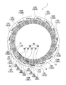
- stator 1 (stator) of this embodiment will be described. As shown in FIGS. 1 to 4, the stator 1 includes a stator core 10 and a coil 12 (coil 12U, coil 12V, coil 12W) and the like.
- the stator core 10 is formed in an annular shape and includes a back yoke 14 and teeth 16.
- the stator core 10 is integrally formed in the circumferential direction.
- the back yoke 14 is formed in an annular shape at the outer peripheral side portion of the stator core 10.
- a plurality of teeth 16 are formed so as to protrude from the inner peripheral surface of the back yoke 14 toward the inside in the radial direction.
- a slot (not shown) is formed between adjacent teeth 16.
- a plurality of coils 12 are mounted so as to be intensively wound around the teeth 16 of the stator core 10 via insulators (not shown) of insulating members.
- the surface of the rectangular conductor forming the coil 12 is enameled to ensure insulation between adjacent rectangular conductors.
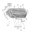
- the coil 12 is an edgewise coil as shown in FIG.
- An edgewise coil is formed by winding a rectangular conductor while bending the rectangular conductor in the short side direction, with one side on the short side in the rectangular cross section of the rectangular conductor as the inner diameter surface and the other surface as the outer diameter surface. Coil.
- the coil 12 is a two-layer coil in which a flat conductor is wound around two layers, an inner layer and an outer layer, as shown in FIG.
- the coil 12 may be a coil in which a flat conductor is wound in three or more layers so as to further include an intermediate layer between the inner layer and the outer layer. That is, the coil 12 may be a multi-layer wound coil formed by winding a rectangular conductor in a plurality of layers in the inner and outer directions of the winding at the winding portion 18.
- the “inner / outer direction of the winding” referred to here is a direction (in the circumferential direction of the stator core 10 in FIG. 3) that passes through the inner side and the outer side of the winding part 18 of the rectangular conductor.
- the coil 12 includes a U-phase coil 12U, a V-phase coil 12V, and a W-phase coil 12W.
- the U-phase coil 12U, the V-phase coil 12V, and the W-phase coil 12W are sequentially arranged along the circumferential direction of the stator core 10, and each U-phase coil 12U, each V-phase coil 12V, and each W-phase are arranged.
- the coils 12 ⁇ / b> W are mounted on the teeth 16 of the stator core 10 at intervals.
- the adjacent coils 12 having the same phase (the same phase among the U phase, the V phase, and the W phase) are electrically connected to each other.
- the stator 1 includes U-phase coils 12U1, 12U2, 12U3, 12U4, 12U5, V-phase coils 12V1, 12V2, 12V3, 12V4, 12V5, and W-phase coils 12W1, 12W2, 12W3. , 12W4, 12W5. Then, along the circumferential direction of the stator core 10, a U-phase coil 12U1, a V-phase coil 12V1, a W-phase coil 12W1, a U-phase coil 12U2, a V-phase coil 12V2, a W-phase coil 12W2, ..., a U-phase coil 12U5, V-phase coil 12V5 and W-phase coil 12W5 are arranged in this order.
- the coil 12 includes a winding portion 18, a bus bar portion 20, a terminal portion 22, and the like as shown in FIGS. In FIGS. 1 to 4, the winding portion 18 is simplified.
- the winding portion 18 is a portion formed by laminating a flat conductor while being wound in an annular shape. Specifically, the winding portion 18 includes an inner end surface 24, an outer end surface 26, an axial end surface 28, an inner end portion 30, an outer end portion 32, and the like.
- the inner end face 24 is an end face formed in the stacking direction of the rectangular conductors, and is arranged inside the stator core 10 in the radial direction when the coil 12 is attached to the stator core 10.
- the outer end face 26 is an end face formed in the stacking direction of the rectangular conductors, and is arranged on the outer side in the radial direction of the stator core 10 when the coil 12 is attached to the stator core 10.
- the axial end face 28 is an end face arranged in the central axis direction of the stator core 10 when the coil 12 is mounted on the stator core 10, and is formed on the side (lead side) where the bus bar portion 20 and the terminal portion 22 are formed. . As shown in FIG. 6, the axial end face 28 corresponds to the outer peripheral face of the rectangular conductor of the outermost layer in the lead side coil end 38.
- the inner end portion 30 is an end portion of a flat conductor that forms the winding portion 18, and is disposed inside the stator core 10 in the radial direction when the coil 12 is attached to the stator core 10.
- the outer end portion 32 is an end portion of a flat conductor that forms the winding portion 18, and is disposed on the outer side in the radial direction of the stator core 10 when the coil 12 is attached to the stator core 10.
- the bus bar portion 20 is a portion formed by drawing a flat conductor from the inner end 30 of the winding portion 18.
- the bus bar portion 20 electrically connects adjacent coils 12 having the same phase.
- the bus bar portion 20 moves from the inner end portion 30 of the winding portion 18 of one U-phase coil 12U (for example, 12U1) toward another adjacent U-phase coil 12U (for example, 12U2).
- the stator core 10 is displaced toward the outside in the radial direction, and is connected to the terminal portion 22 of another U-phase coil 12U.
- the bus-bar part 20 is similarly connected also about V-phase coil 12V and W-phase coil 12W.
- the bus bar portion 20 includes a joint portion 34 and a crossover portion 36.
- the joining portion 34 is a portion that is formed at the distal end portion of the bus bar portion 20 and joined to the terminal portion 22 of another coil 12 (the adjacent in-phase coil 12).
- the crossover portion 36 is a portion formed between the joint portion 34 and the winding portion 18.
- the terminal portion 22 is a portion where a rectangular conductor is drawn out from the outer end portion 32 of the winding portion 18. In the terminal portion 22, the enamel film of the flat conductor is removed. And the terminal part 22 is joined to the junction part 34 of the bus-bar part 20 in the adjacent coil 12 of the same phase.
- the stator 1 connects the inner end 30 of the U-phase coil 12U5, the inner end 30 of the V-phase coil 12V5, and the inner end 30 of the W-phase coil 12W5, respectively. It constitutes a neutral point. Also, external wiring (not shown) is connected to the terminal portion 22 of the U-phase coil 12U1, the terminal portion 22 of the V-phase coil 12V1, and the terminal portion 22 of the W-phase coil 12W1, respectively.
- the coil 12 includes a lead side coil end 38 and an anti-lead side coil end 40 as shown in FIG.
- the coil 12 includes a lane change portion 42 made of a rectangular conductor in the outermost layer of the winding portion 18 in the lead side coil end 38.
- a plurality of (four in the example of FIG. 5) lane change portions 42 are formed with a gap ⁇ in the stacking direction of the rectangular conductors.
- the lane change part 42 is a first lane change part 42A, a second lane change part 42B, a third lane change part 42C, and a fourth lane change part 42D in order from the inner end face 24 side. Further, in the coil 12, in detail, as shown in FIG.
- the coil 12 is formed with three layers of rectangular conductors, and in addition to the lane change portion 42, the innermost layer is formed.
- a plurality of lane change portions 41 made of a rectangular conductor are provided.
- the lane change portion 41 and the lane change portion 42 are portions that are lane changed to adjacent rows in the stacking direction of the flat rectangular conductors.
- the transition part 36 of the bus-bar part 20 is embedded in the coil
- the crossover portion 36 is arranged side by side at the same height as the lane change portion 42 of the coil 12 of the other phase in the central axis direction of the stator core 10.
- transition portion 36 of the bus bar portion 20 of the U-phase coil 12U1 will be described as a representative example.
- the first portion 44 of the transition portion 36 is replaced with the V-phase coil 12V1.
- the first shift portion 46 of the crossover portion 36 is arranged along the circumferential direction so as to be embedded in the winding portion 18 inside the first lane change portion 42A of the first lane change portion 42A, and the V-phase coil 12V1 and the W-phase coil 12W1. It arrange
- the second portion 48 of the crossover portion 36 is placed in the winding portion 18 by a gap ⁇ (see FIGS.
- the second shift part 50 of the crossover part 36 is arranged between the W-phase coil 12W1 and the U-phase coil 12U2 in the radial direction. 1 to 3, the bus bar portion 20 of the U-phase coil 12U1 is shown in color.
- the second portion 48 of the transition portion 36 of the bus bar portion 20 of the U-phase coil 12U1 is replaced by a gap ⁇ between the first lane change portion 42A and the second lane change portion 42B of the W-phase coil 12W1 or the W-phase coil 12W1.
- the third lane change portion 42C and the fourth lane change portion 42D may be embedded in the gap ⁇ .
- first portion 44 of the transition portion 36 of the bus bar portion 20 of the U-phase coil 12U1 may be embedded in any gap ⁇ .
- the second portion 48 of the transition portion 36 is embedded in the gap ⁇ outside the radial direction of the stator core 10 relative to the first portion 44.
- the terminal portion 22 is formed so that the flat conductor is bent at the outer end portion 32 of the winding portion 18 so as to be orthogonal to the central axis direction of the stator core 10.
- the central axis direction of the terminal portion 22 does not coincide with the central axis direction of the stator core 10, and is inclined so as to be orthogonal to the central axis direction of the stator core 10.
- the terminal portion 22 is formed inside the axial end surface 28 of the winding portion 18 in the central axis direction of the stator core 10. Specifically, the position of the upper surface 52 (upper surface in FIG. 4) of the terminal portion 22 is aligned with the position of the axial end surface 28 of the winding portion 18 in the central axis direction of the stator core 10.
- the terminal portion 22 is formed along the circumferential direction of the stator core 10 outside the outer end face 26 of the winding portion 18 in the radial direction of the stator core 10.
- the stator 1 of the first embodiment as described above, the following effects can be obtained.
- the bridging portion 36 of the bus bar portion 20 is embedded in a gap ⁇ between the lane change portions 42 of the other phase coils 12 arranged between the connected in-phase coils 12. Therefore, the coil end height H (see FIG. 4) can be reduced. Therefore, the stator 1 can be reduced in size in the central axis direction. Further, the position of the bus bar portion 20 is stabilized, and the coils 12 having the same phase can be reliably connected to each other by the bus bar portion 20.
- the terminal portion 22 of the coil 12 is formed so that the rectangular conductor is bent at the outer end portion 32 of the winding portion 18 and is orthogonal to the central axis direction of the stator core 10,
- the junction part of the bus-bar part 20 and the terminal part 22 becomes low about a direction.
- the height H of the coil end can be reliably reduced. Therefore, the stator 1 can be reliably downsized in the central axis direction.
- terminal portion 22 of the coil 12 is formed outside the outer end surface 26 of the winding portion 18 in the radial direction of the stator core 10, a work space can be secured outside the outer end surface 26 of the winding portion 18.
- the joining operation of the bus bar portion 20 and the terminal portion 22 becomes easy.
- the terminal portion 22 of the coil 12 is formed along the circumferential direction of the stator core 10.
- the stator 1 can be reduced in size in the radial direction.
- the coil 12 when the coil 12 is sealed with resin after the coil 12 is mounted on the stator core 10, the coil 12 can be reliably sealed with resin even if the width of the back yoke 14 is small.
- the stator 1 when the stator 1 is incorporated in a case (not shown) to form a motor (not shown), a clearance between the joint between the bus bar portion 20 and the terminal portion 22 and the case can be secured, so that the motor is insulated. Performance is improved.
- bus bar portion 20 is drawn from the inner end portion 30 in the winding portion 18, and the terminal portion 22 is drawn from the outer end portion 32 in the winding portion 18.
- a joint portion between the bus bar portion 20 and the terminal portion 22 can be formed at a radially outer position of the stator core 10, so that a rotor (not shown) assembled inside the inner peripheral surface of the stator core 10 is provided. It does not interfere with the joint portion with the portion 22. Therefore, the assembly property of the rotor is good.
- the transition portion 36 of the bus bar portion 20 instead of disposing the transition portion 36 of the bus bar portion 20 in the gap ⁇ between the lane change portions 42 of the coils 12 of the other phase, the outer side of the outermost lane change portion 42 in the radial direction of the stator core 10.
- the transition part 36 of the bus bar part 20 of the U-phase coil 12U1 is taken as an example, the second part 48 of the transition part 36 of the bus bar part 20 of the U-phase coil 12U1 is designated as the second lane of the W-phase coil 12W1.
- an embodiment is conceivable that is placed outside the fourth lane change portion 42D of the W-phase coil 12W1.
- the bus bar portion 20 is formed by pulling a flat conductor from the outer end portion 32 of the winding portion 18, and the terminal portion 22 is formed by pulling a flat conductor from the inner end portion 30 of the winding portion 18.
- the bus bar portion 20 is formed by pulling a flat conductor from the outer end portion 32 of the winding portion 18, and the terminal portion 22 is formed by pulling a flat conductor from the inner end portion 30 of the winding portion 18.
- the transition portion 36 of the bus bar portion 20 is formed as a one-layer winding coil in which the coil 12 is wound by one layer while a gap is formed between adjacent flat conductors at the winding portion 18.
- the flat conductors are arranged so as to be embedded in the gap between the flat conductors is also conceivable.
- the coil 12 is arranged as a coil in which a flat conductor is wound in three or more layers at the winding part 18, and the transition part 36 of the bus bar part 20 is arranged to be embedded in the gap ⁇ between the lane change parts 42.
- An embodiment is also conceivable.
Landscapes
- Engineering & Computer Science (AREA)
- Power Engineering (AREA)
- Insulation, Fastening Of Motor, Generator Windings (AREA)
- Windings For Motors And Generators (AREA)
Abstract
Description
10 ステータコア
12 コイル
14 バックヨーク
16 ティース
18 巻線部
20 バスバー部
22 端末部
24 内側端面
26 外側端面
28 軸方向端面
30 内側端部
32 外側端部
34 接合部
36 渡り部
42 レーンチェンジ部
44 (渡り部の)第1部位
48 (渡り部の)第2部位
δ 隙間
Claims (4)
- 環状のステータコアと、
導体が環状に巻かれる巻線部と、前記巻線部の一方の端部から引き出されるバスバー部と、前記巻線部の他方の端部から引き出される端末部と、を備え、前記ステータコアに複数装着されるコイルと、を有し、
前記バスバー部を他の同相の前記コイルの前記端末部に接続するステータにおいて、
前記コイルは、前記巻線部にて周回の内外方向に前記導体が複数層に巻かれて形成され、前記コイルのコイルエンド部の内周側と外周側に前記導体から成るレーンチェンジ部を複数備える複数層巻コイルであり、
接続される同相の前記コイル同士間に配置される他相の前記コイルの前記レーンチェンジ部間の隙間に前記バスバー部を埋め込ませていること、
を特徴とするステータ。 - 請求項1のステータにおいて、
前記端末部は、前記巻線部の他方の端部にて前記導体が曲げられて前記ステータコアの中心軸方向に対して直交するように形成され、前記ステータコアの径方向について前記巻線部よりも外側に形成されていること、
を特徴とするステータ。 - 請求項2のステータにおいて、
前記端末部は、前記ステータコアの周方向に沿って形成されていること、
を特徴とするステータ。 - 請求項1乃至3のいずれか1つのステータにおいて、
前記バスバー部は前記巻線部における前記ステータコアの径方向の内側の端部から引き出され、
前記端末部は前記巻線部における前記ステータコアの径方向の外側の端部から引き出されていること、
を特徴とするステータ。
Priority Applications (4)
| Application Number | Priority Date | Filing Date | Title |
|---|---|---|---|
| EP13812911.9A EP2833520B1 (en) | 2012-07-03 | 2013-06-28 | Stator |
| KR1020147034000A KR20150014946A (ko) | 2012-07-03 | 2013-06-28 | 스테이터 |
| CN201380030177.XA CN104350667B (zh) | 2012-07-03 | 2013-06-28 | 定子 |
| US14/407,227 US9837869B2 (en) | 2012-07-03 | 2013-06-28 | Stator with bus bar portion embedded between adjacent lane change portions and connected to terminal portion |
Applications Claiming Priority (2)
| Application Number | Priority Date | Filing Date | Title |
|---|---|---|---|
| JP2012-149261 | 2012-07-03 | ||
| JP2012149261A JP5789570B2 (ja) | 2012-07-03 | 2012-07-03 | ステータ |
Publications (1)
| Publication Number | Publication Date |
|---|---|
| WO2014007177A1 true WO2014007177A1 (ja) | 2014-01-09 |
Family
ID=49881933
Family Applications (1)
| Application Number | Title | Priority Date | Filing Date |
|---|---|---|---|
| PCT/JP2013/067903 Ceased WO2014007177A1 (ja) | 2012-07-03 | 2013-06-28 | ステータ |
Country Status (6)
| Country | Link |
|---|---|
| US (1) | US9837869B2 (ja) |
| EP (1) | EP2833520B1 (ja) |
| JP (1) | JP5789570B2 (ja) |
| KR (1) | KR20150014946A (ja) |
| CN (1) | CN104350667B (ja) |
| WO (1) | WO2014007177A1 (ja) |
Cited By (1)
| Publication number | Priority date | Publication date | Assignee | Title |
|---|---|---|---|---|
| DE102018125834A1 (de) * | 2018-10-18 | 2020-04-23 | Dr. Ing. H.C. F. Porsche Aktiengesellschaft | Stator für eine elektrische Maschine und Verfahren zum Herstellen eines derartigen Stators |
Families Citing this family (13)
| Publication number | Priority date | Publication date | Assignee | Title |
|---|---|---|---|---|
| JP6304192B2 (ja) * | 2015-10-20 | 2018-04-04 | トヨタ自動車株式会社 | ステータ |
| US10630127B1 (en) | 2017-01-06 | 2020-04-21 | Apple Inc. | Electric motor with bar wound stator and end turn cooling |
| EP3573215A1 (en) * | 2017-01-18 | 2019-11-27 | Panasonic Intellectual Property Management Co., Ltd. | Molded coil body, method for producing same, motor, and method for assembling stator |
| DE112018000159T9 (de) * | 2017-03-16 | 2019-09-19 | Aisin Aw Co., Ltd. | Stator |
| DE102017207885B4 (de) * | 2017-05-10 | 2021-05-12 | Vitesco Technologies GmbH | Stator für eine elektrische Maschine und elektrische Maschine |
| JP6996407B2 (ja) * | 2018-04-19 | 2022-01-17 | スズキ株式会社 | 固定子コイル及びこれを備えた固定子 |
| EP3629445A1 (en) * | 2018-09-27 | 2020-04-01 | Rolls-Royce Deutschland Ltd & Co KG | A stator and a method for assembling a stator |
| CN111463944B (zh) * | 2019-01-22 | 2021-09-21 | 上海汽车集团股份有限公司 | 定子组件及电机 |
| KR102696292B1 (ko) * | 2020-01-08 | 2024-08-20 | 엘지마그나 이파워트레인 주식회사 | 회전 전기 기기의 스테이터 |
| WO2022107395A1 (ja) * | 2020-11-18 | 2022-05-27 | 株式会社村田製作所 | ステータアッシー、および、ステータアッシーの組み立て方法 |
| EP4016801B1 (en) * | 2020-12-18 | 2025-07-02 | Grundfos Holding A/S | Three-phase stator assembly |
| JP7570266B2 (ja) * | 2021-03-29 | 2024-10-21 | 株式会社日立製作所 | 回転電機の固定子、回転電機、電気駆動システム、及び電動ホイール |
| FR3166497A1 (fr) * | 2024-09-16 | 2026-03-20 | Sonceboz Mechatronics Boncourt Sa | Dispositif d’entrainement à assemblage facilité |
Citations (4)
| Publication number | Priority date | Publication date | Assignee | Title |
|---|---|---|---|---|
| JP2008312290A (ja) * | 2007-06-12 | 2008-12-25 | Toyota Motor Corp | 回転電機 |
| JP2009033832A (ja) * | 2007-07-25 | 2009-02-12 | Aisin Aw Co Ltd | モータ用ステータ |
| JP2009118636A (ja) * | 2007-11-06 | 2009-05-28 | Toyota Motor Corp | 回転電機および回転電機の製造方法 |
| JP2010110122A (ja) | 2008-10-30 | 2010-05-13 | Toyota Motor Corp | 回転電機 |
Family Cites Families (27)
| Publication number | Priority date | Publication date | Assignee | Title |
|---|---|---|---|---|
| US7026739B2 (en) * | 2003-05-23 | 2006-04-11 | Honda Motor Co., Ltd | Stator and insulating bobbin and a manufacturing method of the stator |
| JP2006174547A (ja) * | 2004-12-14 | 2006-06-29 | Mitsubishi Electric Corp | 回転電機の固定子 |
| JP4631631B2 (ja) * | 2005-09-20 | 2011-02-16 | 株式会社デンソー | 回転電機のステータコイル |
| JP4353950B2 (ja) * | 2006-03-06 | 2009-10-28 | 三菱電機株式会社 | 回転電機 |
| JP2008113539A (ja) * | 2006-10-03 | 2008-05-15 | Denso Corp | 交流回転電機 |
| JP4234749B2 (ja) * | 2006-10-19 | 2009-03-04 | 株式会社日立製作所 | 回転電機、クランク形状の連続巻きコイル、分布巻き固定子及びそれらの形成方法 |
| US7830062B2 (en) * | 2006-12-12 | 2010-11-09 | Nidec Corporation | Motor having round and angular coils |
| US7723879B2 (en) * | 2006-12-12 | 2010-05-25 | Nidec Corporation | Motor having multiple busbar plates and wire for the same |
| JP4301334B2 (ja) * | 2007-10-19 | 2009-07-22 | トヨタ自動車株式会社 | 回転電機 |
| DE102009004645A1 (de) * | 2008-02-12 | 2009-08-13 | Ebm-Papst St. Georgen Gmbh & Co. Kg | Elektronisch kommutierter Motor |
| JP5237048B2 (ja) * | 2008-02-13 | 2013-07-17 | 日立オートモティブシステムズ株式会社 | 回転電機、および固定子巻線 |
| JP5363762B2 (ja) * | 2008-06-12 | 2013-12-11 | 株式会社マキタ | 電動工具 |
| JP2010124657A (ja) * | 2008-11-21 | 2010-06-03 | Toyota Motor Corp | 回転電機 |
| JP4670942B2 (ja) * | 2008-11-21 | 2011-04-13 | トヨタ自動車株式会社 | 回転電機 |
| JP2010239691A (ja) * | 2009-03-30 | 2010-10-21 | Denso Corp | 回転電機の固定子及び回転電機 |
| CN102474145B (zh) * | 2009-06-29 | 2014-02-19 | 丰田自动车株式会社 | 多层绕组线圈、定子、及其制造方法 |
| JP5586969B2 (ja) * | 2010-01-21 | 2014-09-10 | 株式会社デンソー | 回転電機の固定子 |
| JP5493906B2 (ja) * | 2010-01-21 | 2014-05-14 | 株式会社デンソー | 回転電機の固定子 |
| JP5234173B2 (ja) * | 2010-06-11 | 2013-07-10 | トヨタ自動車株式会社 | ステータ及びそれに使用される単位コイルの製造方法 |
| JP2012029355A (ja) * | 2010-07-20 | 2012-02-09 | Denso Corp | 回転電機の固定子 |
| IT1401829B1 (it) * | 2010-09-29 | 2013-08-28 | Magneti Marelli Spa | Macchina elettrica presentante un avvolgimento statorico con barre rigide e relativo metodo di costruzione |
| CN102386705B (zh) * | 2011-11-25 | 2013-06-19 | 南车株洲电机有限公司 | 一种电机定子线圈及电机 |
| DE102012010234A1 (de) * | 2012-05-24 | 2013-11-28 | Brose Fahrzeugteile GmbH & Co. Kommanditgesellschaft, Würzburg | Statorsystem für einen Elektromotor |
| DE112013003663B4 (de) * | 2012-07-26 | 2025-01-23 | Mitsubishi Electric Corporation | Elektrische Rotationsmaschine |
| JP6221034B2 (ja) * | 2013-03-29 | 2017-11-01 | 日本電産株式会社 | モータおよびモータの製造方法 |
| JP5862970B2 (ja) * | 2013-06-25 | 2016-02-16 | 株式会社デンソー | 回転電機 |
| JP6029548B2 (ja) * | 2013-07-18 | 2016-11-24 | 本田技研工業株式会社 | 回転電機 |
-
2012
- 2012-07-03 JP JP2012149261A patent/JP5789570B2/ja not_active Expired - Fee Related
-
2013
- 2013-06-28 EP EP13812911.9A patent/EP2833520B1/en active Active
- 2013-06-28 WO PCT/JP2013/067903 patent/WO2014007177A1/ja not_active Ceased
- 2013-06-28 CN CN201380030177.XA patent/CN104350667B/zh active Active
- 2013-06-28 KR KR1020147034000A patent/KR20150014946A/ko not_active Abandoned
- 2013-06-28 US US14/407,227 patent/US9837869B2/en not_active Expired - Fee Related
Patent Citations (4)
| Publication number | Priority date | Publication date | Assignee | Title |
|---|---|---|---|---|
| JP2008312290A (ja) * | 2007-06-12 | 2008-12-25 | Toyota Motor Corp | 回転電機 |
| JP2009033832A (ja) * | 2007-07-25 | 2009-02-12 | Aisin Aw Co Ltd | モータ用ステータ |
| JP2009118636A (ja) * | 2007-11-06 | 2009-05-28 | Toyota Motor Corp | 回転電機および回転電機の製造方法 |
| JP2010110122A (ja) | 2008-10-30 | 2010-05-13 | Toyota Motor Corp | 回転電機 |
Non-Patent Citations (1)
| Title |
|---|
| See also references of EP2833520A4 |
Cited By (1)
| Publication number | Priority date | Publication date | Assignee | Title |
|---|---|---|---|---|
| DE102018125834A1 (de) * | 2018-10-18 | 2020-04-23 | Dr. Ing. H.C. F. Porsche Aktiengesellschaft | Stator für eine elektrische Maschine und Verfahren zum Herstellen eines derartigen Stators |
Also Published As
| Publication number | Publication date |
|---|---|
| US9837869B2 (en) | 2017-12-05 |
| JP2014011934A (ja) | 2014-01-20 |
| EP2833520B1 (en) | 2017-11-22 |
| JP5789570B2 (ja) | 2015-10-07 |
| CN104350667B (zh) | 2017-02-22 |
| KR20150014946A (ko) | 2015-02-09 |
| US20150162793A1 (en) | 2015-06-11 |
| CN104350667A (zh) | 2015-02-11 |
| EP2833520A1 (en) | 2015-02-04 |
| EP2833520A4 (en) | 2017-03-29 |
Similar Documents
| Publication | Publication Date | Title |
|---|---|---|
| JP5789570B2 (ja) | ステータ | |
| JP6033582B2 (ja) | ステータおよびステータの製造方法 | |
| JP5306411B2 (ja) | 回転電機 | |
| JP6053001B2 (ja) | バスバーユニット | |
| JP6058146B2 (ja) | 回転電機 | |
| WO2014007176A1 (ja) | ステータ | |
| JP5989496B2 (ja) | 回転電機のステータ用のバスリング | |
| JP2008253063A (ja) | モータ用ステータ及びその製造方法 | |
| JP6638629B2 (ja) | 回転電機のステータ | |
| EP2690757A2 (en) | Electricity collection and distribution ring and electric motor | |
| JP2018042423A (ja) | コイルおよびコイルを備えた回転電機 | |
| JP5585819B2 (ja) | 回転電機の固定子 | |
| JPWO2018185902A1 (ja) | 回転電機 | |
| JP6210705B2 (ja) | 回転電機およびそれに用いられる固定子 | |
| WO2015092884A1 (ja) | 回転電機 | |
| WO2013179491A1 (ja) | 回転電機、回転電機用ステータおよび車両 | |
| JP5511254B2 (ja) | モータの固定子 | |
| JP5502131B2 (ja) | ステータ、ブラシレスモータ、ステータの製造方法 | |
| WO2014157621A1 (ja) | ステータの構造 | |
| JP5972154B2 (ja) | 回転電機 | |
| JP2017050966A (ja) | 回転電機ステータ | |
| JP2011182579A (ja) | 回転電機 | |
| JP2015119535A (ja) | 回転電機ステータ | |
| JP5874438B2 (ja) | 回転電機の分布巻固定子、および回転電機の分布巻固定子の製造方法 |
Legal Events
| Date | Code | Title | Description |
|---|---|---|---|
| 121 | Ep: the epo has been informed by wipo that ep was designated in this application |
Ref document number: 13812911 Country of ref document: EP Kind code of ref document: A1 |
|
| REEP | Request for entry into the european phase |
Ref document number: 2013812911 Country of ref document: EP |
|
| WWE | Wipo information: entry into national phase |
Ref document number: 2013812911 Country of ref document: EP |
|
| ENP | Entry into the national phase |
Ref document number: 20147034000 Country of ref document: KR Kind code of ref document: A |
|
| WWE | Wipo information: entry into national phase |
Ref document number: 14407227 Country of ref document: US |
|
| NENP | Non-entry into the national phase |
Ref country code: DE |