WO2014010000A1 - レーダシステムおよびデータ処理装置 - Google Patents
レーダシステムおよびデータ処理装置 Download PDFInfo
- Publication number
- WO2014010000A1 WO2014010000A1 PCT/JP2012/004511 JP2012004511W WO2014010000A1 WO 2014010000 A1 WO2014010000 A1 WO 2014010000A1 JP 2012004511 W JP2012004511 W JP 2012004511W WO 2014010000 A1 WO2014010000 A1 WO 2014010000A1
- Authority
- WO
- WIPO (PCT)
- Prior art keywords
- data
- image
- unit
- provisional
- generation unit
- Prior art date
- Legal status (The legal status is an assumption and is not a legal conclusion. Google has not performed a legal analysis and makes no representation as to the accuracy of the status listed.)
- Ceased
Links
Images

Classifications
-
- G—PHYSICS
- G01—MEASURING; TESTING
- G01S—RADIO DIRECTION-FINDING; RADIO NAVIGATION; DETERMINING DISTANCE OR VELOCITY BY USE OF RADIO WAVES; LOCATING OR PRESENCE-DETECTING BY USE OF THE REFLECTION OR RERADIATION OF RADIO WAVES; ANALOGOUS ARRANGEMENTS USING OTHER WAVES
- G01S7/00—Details of systems according to groups G01S13/00, G01S15/00, G01S17/00
- G01S7/02—Details of systems according to groups G01S13/00, G01S15/00, G01S17/00 of systems according to group G01S13/00
- G01S7/28—Details of pulse systems
- G01S7/285—Receivers
- G01S7/295—Means for transforming co-ordinates or for evaluating data, e.g. using computers
-
- G—PHYSICS
- G01—MEASURING; TESTING
- G01S—RADIO DIRECTION-FINDING; RADIO NAVIGATION; DETERMINING DISTANCE OR VELOCITY BY USE OF RADIO WAVES; LOCATING OR PRESENCE-DETECTING BY USE OF THE REFLECTION OR RERADIATION OF RADIO WAVES; ANALOGOUS ARRANGEMENTS USING OTHER WAVES
- G01S13/00—Systems using the reflection or reradiation of radio waves, e.g. radar systems; Analogous systems using reflection or reradiation of waves whose nature or wavelength is irrelevant or unspecified
- G01S13/88—Radar or analogous systems specially adapted for specific applications
- G01S13/89—Radar or analogous systems specially adapted for specific applications for mapping or imaging
- G01S13/90—Radar or analogous systems specially adapted for specific applications for mapping or imaging using synthetic aperture techniques, e.g. synthetic aperture radar [SAR] techniques
- G01S13/9004—SAR image acquisition techniques
- G01S13/9011—SAR image acquisition techniques with frequency domain processing of the SAR signals in azimuth
-
- G—PHYSICS
- G01—MEASURING; TESTING
- G01S—RADIO DIRECTION-FINDING; RADIO NAVIGATION; DETERMINING DISTANCE OR VELOCITY BY USE OF RADIO WAVES; LOCATING OR PRESENCE-DETECTING BY USE OF THE REFLECTION OR RERADIATION OF RADIO WAVES; ANALOGOUS ARRANGEMENTS USING OTHER WAVES
- G01S7/00—Details of systems according to groups G01S13/00, G01S15/00, G01S17/00
- G01S7/02—Details of systems according to groups G01S13/00, G01S15/00, G01S17/00 of systems according to group G01S13/00
- G01S7/40—Means for monitoring or calibrating
-
- G—PHYSICS
- G06—COMPUTING OR CALCULATING; COUNTING
- G06T—IMAGE DATA PROCESSING OR GENERATION, IN GENERAL
- G06T3/00—Geometric image transformations in the plane of the image
- G06T3/40—Scaling of whole images or parts thereof, e.g. expanding or contracting
- G06T3/4053—Scaling of whole images or parts thereof, e.g. expanding or contracting based on super-resolution, i.e. the output image resolution being higher than the sensor resolution
-
- G—PHYSICS
- G06—COMPUTING OR CALCULATING; COUNTING
- G06T—IMAGE DATA PROCESSING OR GENERATION, IN GENERAL
- G06T2207/00—Indexing scheme for image analysis or image enhancement
- G06T2207/10—Image acquisition modality
- G06T2207/10032—Satellite or aerial image; Remote sensing
- G06T2207/10044—Radar image
-
- G—PHYSICS
- G06—COMPUTING OR CALCULATING; COUNTING
- G06T—IMAGE DATA PROCESSING OR GENERATION, IN GENERAL
- G06T2207/00—Indexing scheme for image analysis or image enhancement
- G06T2207/30—Subject of image; Context of image processing
- G06T2207/30181—Earth observation
-
- G—PHYSICS
- G06—COMPUTING OR CALCULATING; COUNTING
- G06T—IMAGE DATA PROCESSING OR GENERATION, IN GENERAL
- G06T2210/00—Indexing scheme for image generation or computer graphics
- G06T2210/36—Level of detail
Definitions
- the present invention relates to a radar system and a data processing apparatus that are mounted on a moving body such as a satellite or an aircraft and observe an object such as the ground surface.
- Synthetic Aperture Radar is a device that is mounted on a moving body such as a satellite or an aircraft and observes an object such as the ground surface with high resolution.
- This radar normally radiates radio waves in a direction substantially orthogonal to the moving direction of the moving body. Then, in the ground area irradiated with radio waves, the direction parallel to the moving direction of the moving object is obtained by synthetic aperture processing, and the radio wave radiation direction (distance direction) is obtained by obtaining resolution by pulse compression processing. It is carried out.
- the synthetic aperture process is a process for improving the angular resolution.
- the angular resolution of a radar is determined by the size of an antenna used when radiating radio waves into space, and the higher the antenna aperture, the higher the angular resolution.
- the size of an antenna that can be mounted is limited. Therefore, in SAR, observation is performed while moving, and the received signal obtained in a fixed time is synthesized by signal processing, thereby obtaining an angular resolution equivalent to that of an antenna having an opening having the same size as the moving path length.
- Patent Document 1 shows an example of a signal processing method.
- high-accuracy signal processing is performed in consideration of the fact that the satellite orbit is a curve in order to obtain a high-resolution image.
- angular resolution is obtained by performing Doppler frequency analysis on the received signal. That is, when the same target point is observed for a long time, the relative speed between the radar and the target point changes during the observation time. As a result, the received signal at the target point has a Doppler frequency bandwidth corresponding to the amount of change in relative speed. As the Doppler frequency width is wider, the amount of information related to the angle at which the target is present increases, so the angular resolution is improved.
- the SAR pulse compression processing is performed to obtain distance resolution. For this reason, radio wave radiation is pulsed. That is, the SAR is a kind of pulse Doppler radar that emits a pulse wave. Therefore, the Doppler frequency analysis for obtaining the angular resolution is performed on the received signal discretized at the pulse repetition frequency (PRF).
- PRF pulse repetition frequency
- the received signal of SAR since the received signal of SAR is generally a large data size, it may be transmitted to the ground equipment after data compression processing.
- the signal before the image reproduction process since the signal before the image reproduction process has high randomness, there is a restriction in increasing the efficiency of data compression.
- the randomness of the image data is reduced, so that the data compression efficiency can be increased.
- the present invention has been made in order to solve the above-described problems, and an object of the present invention is to provide a radar system and a data processing apparatus that can obtain an image with no degradation in resolution while reducing the amount of data transmission. It is said.
- a radar system includes an observation device mounted on a moving body for observing an object, and a data processing device for processing data from the observation device.
- the observation device radiates a predetermined radar wave to the outside.
- a transmission / reception unit that receives the radar wave scattered by an object existing outside to acquire a reception signal
- a provisional image generation unit that generates a provisional image from the reception signal acquired by the transmission / reception unit, and provisional image generation
- a data transmission unit for transmitting the provisional image generated by the data transmission unit to the data processing device, the data processing unit received by the data reception unit for receiving the provisional image transmitted by the data transmission unit, and the data reception unit
- the apparatus includes an provisional image and an image generation unit that generates an image from trajectory data of the moving object.
- FIG. 1 is a block diagram showing a configuration of a radar system according to Embodiment 1 of the present invention. As shown in FIG. 1, the radar system includes an observation device 1 and a data processing device 2.
- the observation apparatus 1 is mounted on a moving body and observes an object.
- the observation apparatus 1 includes a transmission unit 11, a transmission / reception switch 12, an antenna 13, a reception unit 14, a provisional image generation unit 15, a data compression unit 16, and a data transmission unit 17.
- the transmission unit 11 generates a predetermined pulsed radar wave.
- the radar wave generated by the transmitter 11 is output to the transmission / reception switch 12.
- the transmission / reception switch 12 selectively switches the output destination of the input wave.
- the transmission / reception switch 12 outputs the radar wave from the transmission unit 11 from the antenna 13 to the space, and outputs the radar wave from the antenna 13 to the reception unit 14.
- the radar wave from the antenna 13 and the transmission / reception switch 12 is radiated to the outside (space), and a part of the radar wave (scattered wave) scattered by the object (observation target) existing outside is received. Radar waves received by the antenna 13 are output to the transmission / reception switch 12.
- the receiver 14 receives the radar wave from the transmission / reception switch 12. And the receiving part 14 amplifies the said radar wave, and converts it into a low frequency received signal by frequency conversion.
- the reception signal converted by the reception unit 14 is output to the provisional image generation unit 15.
- the transmission unit 11, the transmission / reception switching unit 12, the antenna 13 and the reception unit 14 constitute a transmission / reception unit of the present invention.
- the provisional image generation unit 15 generates a provisional image (low-resolution image) based on the reception signal from the reception unit 14.
- the provisional image generated by the provisional image generation unit 15 is output to the data compression unit 16.
- the data compression unit 16 performs data compression processing on the provisional image from the provisional image generation unit 15 to generate compressed image data.
- the compressed image data generated by the data compression unit 16 is output to the data transmission unit 17.
- the data transmission unit 17 transmits the compressed image data from the data compression unit 16 to the remote data processing device 2.
- the data processing device 2 is installed in the data receiving facility and processes data from the observation device 1.
- the data receiving equipment is generally ground equipment.
- the data receiving facility is not limited to the ground facility, and may be owned by, for example, a ship or an aircraft.
- the data processing device 2 includes a data receiving unit 21, a data decompressing unit 22, a data restoring unit 23, and an image generating unit 24.
- the data receiving unit 21 receives the compressed image data from the data transmitting unit 17 of the observation apparatus 1.
- the compressed image data received by the data receiving unit 21 is output to the data decompressing unit 22.
- the data decompression unit 22 decompresses the compressed image data from the data reception unit 21 to obtain the original provisional image.
- the provisional image obtained by the data decompression unit 22 is output to the data restoration unit 23.
- the data restoration unit 23 performs a reverse process on the azimuth compression process in the image reproduction process in the temporary image generation unit 15 for the temporary image from the data decompression unit 22 to temporarily convert the signal before the azimuth compression. It is something to return.
- the image restored to the signal before azimuth compression by the data restoration unit 23 is output to the image generation unit 24.
- the image generation unit 24 uses high-precision trajectory data of the moving object on which the observation apparatus 1 is mounted, and generates an image with higher resolution than the provisional image generation unit 15 based on the image from the data restoration unit 23. It is. The image generated by the image generation unit 24 is output to the outside.
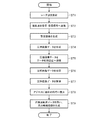
- the transmitter 11 generates a predetermined pulsed radar wave and radiates it from the antenna 13 via the transmission / reception switch 12 (step ST1).
- the antenna 13 receives a part of the radar wave (scattered wave) scattered by an object existing outside, and outputs it to the receiving unit 14 via the transmission / reception switch 12.
- the receiver 14 amplifies the radar wave and converts it into a low-frequency received signal by frequency conversion (step ST2).
- the reception signal received / converted by the reception unit 14 is output to the provisional image generation unit 15.
- the provisional image generation unit 15 generates a provisional image based on the reception signal from the reception unit 14 (step ST3).
- SAR a received signal is obtained in a two-dimensional space defined by two axes, a distance axis and an azimuth axis.
- the provisional image generation unit 15 improves the distance resolution by the pulse compression process and improves the azimuth resolution by the azimuth compression process. Since the pulse compression processing and the azimuth compression processing are the same as the conventionally known methods, the details are not particularly described here, but the data compression processing and the coherent integration processing in the azimuth axis direction are generally configured.
- Data compensation processing may be performed on the azimuth axis, or data may be converted on the azimuth frequency axis by Fourier transform, and data compensation processing may be performed there.
- a Fourier transform is generally used in order to improve the efficiency of the operation.
- the data compression unit 16 performs data compression processing on the temporary image from the temporary image generation unit 15 to generate compressed image data (step ST4).
- the data size of the compressed image data becomes smaller than the data size of the original image.
- the type of data compression method is not particularly limited, and a generally known method may be used. For example, JPEG compression may be performed.
- the compressed image data generated by the data compression unit 16 is output to the data transmission unit 17.
- the data transmission unit 17 transmits the compressed image data from the data compression unit 16 to the remote data processing device 2 (step ST5). That is, the compressed image data is transmitted from the observation device 1 mounted on the moving body by the data transmission unit 17 to the data processing device 2 installed in the remote data reception facility. For this transmission, a data transmission method similar to that used in general SAR satellites may be used.
- the data reception unit 21 of the data processing device 2 receives the compressed image data from the data transmission unit 17 of the observation device 1 (step ST6).
- the compressed image data received by the data receiving unit 21 is output to the data decompressing unit 22.
- the data decompression unit 22 decompresses the compressed image data from the data reception unit 21 to obtain the original provisional image (step ST7). If the data compression method used by the data compression unit 16 is reversible, the provisional image obtained by the data decompression unit 22 is exactly the same as the provisional image generated by the provisional image generation unit 15. When an irreversible data compression method is used with priority given to compression efficiency, the provisional image obtained by the data decompression unit 22 is added with noise generated by the compression. The provisional image obtained by the data decompression unit 22 is output to the data restoration unit 23.
- the data restoration unit 23 performs a reverse process on the azimuth compression process in the image reproduction process in the temporary image generation unit 15 for the provisional image from the data decompression unit 22 to thereby obtain a signal before azimuth compression.
- a technique called a chirp scaling method is used in the provisional image generation unit 15.
- image reproduction is performed by multiplication of a Fourier transform and a phase compensation coefficient. Therefore, the data restoration unit 23 performs inverse Fourier transform and divides the phase value multiplied by the provisional image generation unit 15 to obtain a signal before azimuth compression.
- the provisional image generation unit 15 is in a state called when using low-precision trajectory data. The image restored by the data restoration unit 23 is output to the image generation unit 24.
- the image generation unit 24 generates high-resolution images by performing azimuth compression processing based on the provisional image from the data restoration unit 23 using the highly accurate trajectory data of the moving body (step ST9). . That is, a high-resolution image reproduction process is performed on the obtained signal before azimuth compression (the azimuth compression process is performed with a higher azimuth resolution than the azimuth compression process performed by the provisional image generation unit 15). Is generated. In this highly accurate image reproduction process, more accurate trajectory data than simple trajectory data in the provisional image generation unit 15 is used.
- the data compression efficiency at the time of data transmission from the moving body to the data receiving facility is increased, and the data transmission amount is reduced. Can be reduced. As a result, data transmission can be performed in a short time. Further, data transmission is possible even with the data transmission unit 17 and the data reception unit 21 having low data transmission capability. For example, since the antenna gains of the data transmission unit 17 and the data reception unit 21 may be low, the antenna size can be reduced. In addition, since image reproduction processing is performed using highly accurate orbit data after data transmission, an image with high resolution can be obtained.
- the data compression unit 16 of the observation device 1 compresses the image data and then transmits the image data to the data processing device 2.
- the data decompression unit 22 of the data processing device 2 decompresses the compressed data.
- the original image is extracted, but the data compression unit 16 and the data decompression unit 22 are omitted, and the provisional image generated by the provisional image generation unit 15 may be transmitted to the data processing apparatus 2 as it is. Good.
- image reproduction processing including azimuth compression processing, pulse compression processing, or both, the data size after processing is smaller than before processing even when data compression is not performed. For this reason, the amount of data transmission can be reduced without performing data compression by performing these processes with the observation device.
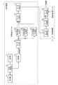
- FIG. 3 is a block diagram showing the configuration of the radar system according to Embodiment 2 of the present invention.
- the radar system according to Embodiment 2 shown in FIG. 3 changes the provisional image generation unit 15 of the radar system according to Embodiment 1 shown in FIG. 1 to a data division unit 18 and a plurality of provisional image generation units 15b.
- the data restoration unit 23 and the image generation unit 24 are changed to a data combination unit (image generation unit) 25.
- Other configurations are the same, and the same reference numerals are given and description thereof is omitted.
- the data dividing unit 18 divides the reception signal from the receiving unit 14 into a plurality of sections in the time direction, and outputs the divided signals to each provisional image generating unit 15b.
- Each provisional image generation unit 15b generates a plurality of provisional images (low-resolution images) based on the received signals for each section from the data division unit 18.
- the provisional images generated by the provisional image generation units 15b are output to the data compression unit 16, respectively.
- the data combination unit 25 combines a plurality of provisional images from the data decompression unit 22 to generate one high resolution image.
- the image generated by the data combination unit 25 is output to the outside.
- the radar system has a configuration in which an image reproducing method known as a sub-aperture method is shared and executed by the observation device 1 and the data processing device 2.
- the sub-aperture method is disclosed in Patent Document 1, for example.
- the received signal obtained during the synthetic aperture is first divided in the time direction.
- each provisional image generator 15b performs low-resolution provisional image reproduction for each signal of the divided small sections.
- azimuth compression is performed with a short synthetic opening time, the azimuth resolution is low. Since each temporary image has a low resolution, the accuracy of the trajectory data used here (temporary trajectory data obtained on the trajectory) may be lower than the trajectory data used in the data processing device 2 described later.
- the data compression unit 16 collectively compresses the plurality of provisional images generated by the plurality of provisional image generation units 15b.
- a plurality of provisional images may be simply connected to form one data and then compressed, or the data may be compressed for each provisional image and the compressed data is collected. You may do it.
- the amount of data after imaging is smaller than that before imaging.
- the efficiency of data compression is increased. As a result, the data size is expected to be smaller than when an unprocessed received signal is transmitted.
- the compressed data is returned to the data at the output stage of the provisional image generation unit 15b, that is, a plurality of provisional images, through the data transmission unit 17, the data reception unit 21, and the data decompression unit 22.
- the data combining unit 25 combines a plurality of provisional images to generate one high resolution image. Since the specific processing procedure is the same as that of Patent Document 1, it will not be described in detail here. However, since the image generated here has a high resolution, the accuracy of the orbit data is required to be higher than that required by the processing in the observation apparatus 1 described above.
- the amount of data transmission from the observation device 1 to the data processing device 2 can be reduced by performing processing up to provisional imaging in the observation device 1, and High-resolution images can be obtained by signal processing in the data processing device 2.
- Embodiment 3 shows a case where both the pulse compression processing and the azimuth compression processing are performed in the observation apparatus 1 has been described.
- Embodiment 3 shows a case where only pulse compression processing is performed.
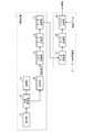
- 4 is a block diagram showing a configuration of a radar system according to Embodiment 3 of the present invention.
- the radar system according to Embodiment 3 shown in FIG. 4 changes the provisional image generation unit 15 of the radar system according to Embodiment 1 shown in FIG. 1 to a pulse compression unit (provisional image generation unit) 19 to generate an image.
- the unit 24 is changed to an azimuth compression unit (image generation unit) 26 and the data restoration unit 23 is deleted.
- Other configurations are the same, and the same reference numerals are given and description thereof is omitted.
- the pulse compression unit 19 generates a provisional image with high distance resolution by performing only the pulse compression processing based on the reception signal from the reception unit 14.
- the provisional image generated by the pulse compression unit 19 is output to the data compression unit 16.
- the data compression unit 16 performs data compression processing on the provisional image from the pulse compression unit 19 to generate compressed image data.
- the pulse compression unit 19 can obtain a high-resolution image in the distance axis direction. Even before data compression, the amount of data is reduced by the pulse width. Furthermore, since the distance resolution is improved, the efficiency of data compression by the data compression unit 16 is increased. In addition, since the pulse compression process is a process that does not depend on the trajectory of the moving object, the observation device 1 mounted on the moving object does not require orbit data.
- the azimuth compression unit 26 generates a high-resolution image by performing azimuth compression processing that increases the azimuth resolution based on the provisional image from the data decompression unit 22 using the trajectory data of the moving object.
- the image generated by the azimuth compression unit 26 is output to the outside.
- the same effect as that of the first embodiment can be obtained even when only the pulse compression processing is performed when the provisional image is generated on the moving body. it can.
- a radar system and a data processing device include an observation device that is mounted on a moving body and observes an object, and a data processing device that processes data from the observation device.
- the observation device includes a predetermined radar wave.
- a transmission / reception unit that receives the radar wave scattered by an object existing outside and acquires a reception signal; and a provisional image generation unit that generates a provisional image from the reception signal acquired by the transmission / reception unit;
- a data transmission unit that transmits the provisional image generated by the provisional image generation unit to the data processing device, the data processing device including a data reception unit that receives the provisional image transmitted by the data transmission unit, and a data reception unit
- an image generation unit that generates an image from the trajectory data of the moving object, and obtains an image with no degradation in resolution while reducing the data transmission amount.
- synthetic aperture radar it can be applied to (SAR Synthetic Aperture Radar).
- 1 observation device 2 data processing device, 11 transmission unit, 12 transmission / reception switch, 13 antenna, 14 reception unit, 15, 15b provisional image generation unit, 16 data compression unit, 17 data transmission unit, 18 data division unit, 19 pulses Compression unit, 21 data reception unit, 22 data decompression unit, 23 data restoration unit, 24 image generation unit, 25 data combination unit, 26 azimuth compression unit.
Landscapes
- Engineering & Computer Science (AREA)
- Remote Sensing (AREA)
- Radar, Positioning & Navigation (AREA)
- Physics & Mathematics (AREA)
- General Physics & Mathematics (AREA)
- Computer Networks & Wireless Communication (AREA)
- Electromagnetism (AREA)
- Signal Processing (AREA)
- Theoretical Computer Science (AREA)
- Radar Systems Or Details Thereof (AREA)
- Compression, Expansion, Code Conversion, And Decoders (AREA)
Abstract
Description
そこで、SARでは、移動しながら観測を行い、一定時間に得た受信信号を信号処理で合成することにより、移動経路長と同じ大きさの開口を持つアンテナと同等の角度分解能を得ている。例えば、特許文献1に信号処理手法の例が示されている。この特許文献1では、高分解能画像を得るために、衛星軌道が曲線であることを考慮した高精度な信号処理を行っている。
実施の形態1.
図1はこの発明の実施の形態1に係るレーダシステムの構成を示すブロック図である。
レーダシステムは、図1に示すように、観測装置1およびデータ処理装置2から構成されている。
送受切替器12は、入力波の出力先を選択的に切り替えるものである。この送受切替器12は、送信部11からのレーダ波を空中線13から空間へ出力し、空中線13からのレーダ波を受信部14へ出力する。
なお、送信部11、送受切替部12、空中線13および受信部14は、本発明の送受信部を構成する。
データ送信部17は、データ圧縮部16からの圧縮画像データを遠隔のデータ処理装置2へ送信するものである。
レーダシステムの動作では、図2に示すように、まず、送信部11は所定のパルス状のレーダ波を生成し、送受切替器12を経由して空中線13から外部へ放射する(ステップST1)。
次いで、空中線13は、外部に存在する物体により散乱されたレーダ波(散乱波)の一部を受信し、送受切替器12を経由して受信部14へ出力する。そして、受信部14は、このレーダ波の増幅を行うとともに、周波数変換により低周波の受信信号へと変換する(ステップST2)。この受信部14により受信・変換された受信信号は暫定画像生成部15へ出力される。
ここで、SARでは、距離軸およびアジマス軸の2軸で定義される2次元空間上で受信信号が得られる。画像再生処理前は、距離軸方向およびアジマス軸方向にぼけた画像となっている。そこで、暫定画像生成部15は、パルス圧縮処理により距離分解能を改善し、アジマス圧縮処理によりアジマス分解能を改善する。パルス圧縮処理およびアジマス圧縮処理については、従来から知られている手法と同様であるため、特にここでは詳細を述べないが、一般にデータ補償処理とアジマス軸方向のコヒーレント積分処理で構成される。データ補償処理はアジマス軸上で行われる場合と、フーリエ変換によりアジマス周波数軸上にデータを変換し、そこでデータ補償処理を行う場合がある。コヒーレント積分は演算の効率化のため、一般にはフーリエ変換が用いられる。
このデータ圧縮部16により生成された圧縮画像データはデータ送信部17へ出力される。
実施の形態1では、観測装置1で生成した画像をデータ処理装置2で受信した後、データ復元部23でアジマス圧縮前の信号に一旦戻す構成を示した。それに対して、実施の形態2では、アジマス圧縮を観測装置1で途中まで行い、データ処理装置2でアジマス圧縮処理の残った部分を実行する場合について示す。
図3はこの発明の実施の形態2に係るレーダシステムの構成を示すブロック図である。この図3に示す実施の形態2に係るレーダシステムは、図1に示す実施の形態1に係るレーダシステムの暫定画像生成部15をデータ分割部18および複数の暫定画像生成部15bに変更し、データ復元部23および画像生成部24をデータ結合部(画像生成部)25に変更したものである。その他の構成は同様であり、同一の符号を付してその説明を省略する。
各暫定画像生成部15bは、データ分割部18からの区間毎の受信信号に基づいて、複数の暫定画像(低分解能な画像)を生成するものである。この各暫定画像生成部15bにより生成された暫定画像はそれぞれデータ圧縮部16へ出力される。
サブアパーチャ法は合成開口中に得られる受信信号をまず時間方向に分割する。そして、分割後の小区間の信号毎に、各暫定画像生成部15bにて低分解能な暫定画像再生を行う。ここでの処理では、短い合成開口時間でのアジマス圧縮となるため、アジマス分解能は低い。個々の暫定画像が低分解能であることから、ここで用いる軌道データ(軌道上で得られた暫定軌道データ)の精度は、後述のデータ処理装置2で利用する軌道データより低くても良い。
画像化後のデータ量は画像化前に比べて小さくなる。また、画像化されているため、データ圧縮の効率が高くなる。以上により、未処理の受信信号を伝送するよりもデータサイズは小さくなると期待される。
実施の形態1では、観測装置1にてパルス圧縮処理およびアジマス圧縮処理の両方を行う場合について示した。それに対して、実施の形態3では、パルス圧縮処理のみを行う場合について示す。
図4はこの発明の実施の形態3に係るレーダシステムの構成を示すブロック図である。この図4に示す実施の形態3に係るレーダシステムは、図1に示す実施の形態1に係るレーダシステムの暫定画像生成部15をパルス圧縮部(暫定画像生成部)19に変更し、画像生成部24をアジマス圧縮部(画像生成部)26に変更し、データ復元部23を削除したものである。その他の構成は同様であり、同一の符号を付してその説明を省略する。
なお、データ圧縮部16は、パルス圧縮部19からの暫定画像に対してデータ圧縮処理を施し、圧縮画像データを生成する。
また、パルス圧縮処理は、移動体の軌道に依存しない処理であるため、移動体に搭載された観測装置1では軌道データが不要となる。
Claims (6)
- 移動体に搭載されて物体の観測を行う観測装置と、前記観測装置からのデータを処理するデータ処理装置とを備えたレーダシステムにおいて、
前記観測装置は、
所定のレーダ波を外部に放射し、外部に存在する物体により散乱された当該レーダ波を受信して受信信号を取得する送受信部と、
前記送受信部により取得された受信信号から暫定画像を生成する暫定画像生成部と、
前記暫定画像生成部により生成された暫定画像を前記データ処理装置へ送信するデータ送信部とを備え、
前記データ処理装置は、
前記データ送信部により送信された暫定画像を受信するデータ受信部と、
前記データ受信部により受信された暫定画像と移動体の軌道データから画像を生成する画像生成部とを備えた
ことを特徴とするレーダシステム。 - 前記観測装置は、
前記暫定画像生成部により生成された暫定画像にデータ圧縮処理を施し、圧縮画像データを生成するデータ圧縮部を備え、
前記データ送信部は、前記暫定画像生成部により生成された暫定画像に代えて、前記データ圧縮部により生成された圧縮画像データを前記データ処理装置へ送信し、
前記データ処理装置は、
前記データ受信部は、前記データ送信部により送信された圧縮画像データを受信し、
前記データ受信部により受信された圧縮画像データを解凍して前記暫定画像を得るデータ解凍部を備え、
前記画像生成部は、前記データ解凍部により得られた暫定画像から画像を生成する
ことを特徴とする請求項1記載のレーダシステム。 - 前記暫定画像生成部は、前記受信信号に対してパルス圧縮処理を行うことにより距離分解能の高い暫定画像を生成し、
前記画像生成部は、前記暫定画像に対してアジマス分解能を高めるアジマス圧縮処理を行う
ことを特徴とする請求項1記載のレーダシステム。 - 前記暫定画像生成部は、軌道上で得られた暫定軌道データを用いて、前記受信信号に対して暫定的にアジマス圧縮処理を行い、
前記画像生成部は、前記暫定画像に対して、前記暫定軌道データより高い精度の軌道データを用いてアジマス圧縮処理を行う
ことを特徴とする請求項1記載のレーダシステム。 - 前記暫定画像生成部は、前記受信信号を時間方向に複数の区間で分割し、当該区間毎の受信信号を用いて複数の暫定画像を生成し、
前記画像生成部は、前記複数の暫定画像を組み合わせて、1つの画像を生成する
ことを特徴とする請求項4記載のレーダシステム。 - 移動体に搭載されて物体の観測を行う観測装置からのデータを処理するデータ処理装置において、
前記観測装置が所定のレーダ波を外部に放射し、外部に存在する物体により散乱された当該レーダ波を受信して受信信号を取得し、当該受信信号から生成した暫定画像を、受信するデータ受信部と、
前記データ受信部により受信された暫定画像と移動体の軌道データから画像を生成する画像生成部とを備えた
ことを特徴とするデータ処理装置。
Priority Applications (4)
| Application Number | Priority Date | Filing Date | Title |
|---|---|---|---|
| EP12881094.2A EP2873987B1 (en) | 2012-07-12 | 2012-07-12 | Radar system and data processing device |
| PCT/JP2012/004511 WO2014010000A1 (ja) | 2012-07-12 | 2012-07-12 | レーダシステムおよびデータ処理装置 |
| JP2014524498A JP5901767B2 (ja) | 2012-07-12 | 2012-07-12 | レーダシステム、観測装置およびデータ処理装置 |
| US14/371,398 US9442193B2 (en) | 2012-07-12 | 2012-07-12 | Radar system and data processing device |
Applications Claiming Priority (1)
| Application Number | Priority Date | Filing Date | Title |
|---|---|---|---|
| PCT/JP2012/004511 WO2014010000A1 (ja) | 2012-07-12 | 2012-07-12 | レーダシステムおよびデータ処理装置 |
Publications (1)
| Publication Number | Publication Date |
|---|---|
| WO2014010000A1 true WO2014010000A1 (ja) | 2014-01-16 |
Family
ID=49915504
Family Applications (1)
| Application Number | Title | Priority Date | Filing Date |
|---|---|---|---|
| PCT/JP2012/004511 Ceased WO2014010000A1 (ja) | 2012-07-12 | 2012-07-12 | レーダシステムおよびデータ処理装置 |
Country Status (4)
| Country | Link |
|---|---|
| US (1) | US9442193B2 (ja) |
| EP (1) | EP2873987B1 (ja) |
| JP (1) | JP5901767B2 (ja) |
| WO (1) | WO2014010000A1 (ja) |
Cited By (2)
| Publication number | Priority date | Publication date | Assignee | Title |
|---|---|---|---|---|
| WO2018155683A1 (ja) * | 2017-02-24 | 2018-08-30 | 国立研究開発法人宇宙航空研究開発機構 | 飛翔体、及びプログラム |
| CN113811786A (zh) * | 2019-05-17 | 2021-12-17 | 三菱电机株式会社 | 天线装置及雷达装置 |
Families Citing this family (15)
| Publication number | Priority date | Publication date | Assignee | Title |
|---|---|---|---|---|
| CA2980920C (en) | 2015-03-25 | 2023-09-26 | King Abdulaziz City Of Science And Technology | Apparatus and methods for synthetic aperture radar with digital beamforming |
| WO2018217902A1 (en) | 2017-05-23 | 2018-11-29 | King Abdullah City Of Science And Technology | Synthetic aperture radar imaging apparatus and methods for moving targets |
| EP3631506A4 (en) * | 2017-05-23 | 2020-11-04 | King Abdullah City of Science and Technology | APPARATUS AND METHODS FOR SYNTHESIS OF APERTURE RADAR EQUIPPED WITH A MULTI-APERTURE ANTENNA |
| US12199644B1 (en) | 2023-12-12 | 2025-01-14 | Atombeam Technologies Inc | System and method for homomorphic compression using latent space preprocessing and neural upsampling |
| US12231151B1 (en) | 2017-10-30 | 2025-02-18 | Atombeam Technologies Inc | Federated large codeword model deep learning architecture with homomorphic compression and encryption |
| US12058333B1 (en) * | 2023-12-12 | 2024-08-06 | AtomBeam Technologies Inc. | System and methods for upsampling of decompressed data after lossy compression using a neural network |
| US12261631B2 (en) | 2017-10-30 | 2025-03-25 | Atombeam Technologies Inc | Deep learning using large codeword model with homomorphically compressed data |
| US12294640B1 (en) | 2023-12-12 | 2025-05-06 | Atombeam Technologies Inc | System and method for distributed edge-cloud homomorphic compression using adaptive neural networks |
| US12493569B2 (en) | 2023-12-12 | 2025-12-09 | AtomBeam Technologies Inc. | System and method for energy-aware distributed edge-cloud homomorphic compression using adaptive neural networks |
| US12602586B2 (en) | 2024-05-23 | 2026-04-14 | Atombeam Technolgies Inc. | Supervisory neuron for continuously adaptive neural network |
| US12469179B2 (en) | 2023-12-12 | 2025-11-11 | AtomBeam Technologies Inc. | System and methods for upsampling of decompressed data after lossy compression using a neural network |
| US12579437B2 (en) | 2024-05-23 | 2026-03-17 | AtomBeam Technologies Inc. | Mobile-optimized multi-stage LLM with federated persistent cognitive architecture |
| US12572830B1 (en) | 2024-05-23 | 2026-03-10 | AtomBeam Technologies Inc. | System and method for enterprise hierarchical persistent cognitive machines with organizational hierarchy awareness and compliance integration |
| US12506496B2 (en) | 2024-05-23 | 2025-12-23 | AtomBeam Technologies Inc. | Hierarchical smart caching for machine learning codeword responses |
| CN121069314B (zh) * | 2025-11-10 | 2025-12-30 | 珠海正和微芯科技有限公司 | 雷达数据传输方法及雷达系统 |
Citations (4)
| Publication number | Priority date | Publication date | Assignee | Title |
|---|---|---|---|---|
| JPH09178846A (ja) * | 1995-12-27 | 1997-07-11 | Nec Corp | 衛星搭載合成開口レーダ |
| JPH11183607A (ja) * | 1997-12-25 | 1999-07-09 | Mitsubishi Electric Corp | 合成開口レーダ装置 |
| JP2005024395A (ja) * | 2003-07-02 | 2005-01-27 | Toshiba Corp | レーダ装置およびレーダシステム |
| JP2011169869A (ja) | 2010-02-22 | 2011-09-01 | Mitsubishi Electric Corp | レーダ信号処理装置 |
Family Cites Families (6)
| Publication number | Priority date | Publication date | Assignee | Title |
|---|---|---|---|---|
| JPH02210285A (ja) * | 1989-02-10 | 1990-08-21 | Mitsubishi Electric Corp | スポットライトマッピングレーダ装置 |
| US5608404A (en) * | 1993-06-23 | 1997-03-04 | The United States Of America As Represented By The United States Department Of Energy | Imaging synthetic aperture radar |
| US7411540B1 (en) * | 2005-03-10 | 2008-08-12 | Itt Manufacturing Enterprises Inc. | Synthetic aperture radar (SAR) data compression |
| JP4698617B2 (ja) * | 2007-01-17 | 2011-06-08 | 三菱電機株式会社 | 画像伝送装置及び画像伝送方法 |
| JP5312150B2 (ja) * | 2009-03-31 | 2013-10-09 | 三菱スペース・ソフトウエア株式会社 | SAR(SyntheticApertureRadar)重畳データ生成装置、SAR重畳データ再生装置、SAR重畳データ生成プログラム、SAR重畳データ再生プログラム、SAR重畳データ生成方法およびSAR重畳データ再生方法 |
| CA2828923A1 (en) * | 2011-03-10 | 2012-09-13 | Astrium Limited | Sar data processing |
-
2012
- 2012-07-12 WO PCT/JP2012/004511 patent/WO2014010000A1/ja not_active Ceased
- 2012-07-12 US US14/371,398 patent/US9442193B2/en active Active
- 2012-07-12 EP EP12881094.2A patent/EP2873987B1/en active Active
- 2012-07-12 JP JP2014524498A patent/JP5901767B2/ja active Active
Patent Citations (4)
| Publication number | Priority date | Publication date | Assignee | Title |
|---|---|---|---|---|
| JPH09178846A (ja) * | 1995-12-27 | 1997-07-11 | Nec Corp | 衛星搭載合成開口レーダ |
| JPH11183607A (ja) * | 1997-12-25 | 1999-07-09 | Mitsubishi Electric Corp | 合成開口レーダ装置 |
| JP2005024395A (ja) * | 2003-07-02 | 2005-01-27 | Toshiba Corp | レーダ装置およびレーダシステム |
| JP2011169869A (ja) | 2010-02-22 | 2011-09-01 | Mitsubishi Electric Corp | レーダ信号処理装置 |
Non-Patent Citations (2)
| Title |
|---|
| "Gosei Kaiko Rader ni yoru Remote Sensing no Shoyoka ni Mukete no Feasibility Study", THE MECHANICAL SOCIAL SYSTEMS FOUNDATION, March 2007 (2007-03-01), pages 21 - 29, XP008175456, Retrieved from the Internet <URL:http://www.jspacesystems.or.jp/jaros/kisikyou18sar_rimosen_shouyouka_fs.pdf> [retrieved on 20120727] * |
| See also references of EP2873987A4 * |
Cited By (5)
| Publication number | Priority date | Publication date | Assignee | Title |
|---|---|---|---|---|
| WO2018155683A1 (ja) * | 2017-02-24 | 2018-08-30 | 国立研究開発法人宇宙航空研究開発機構 | 飛翔体、及びプログラム |
| JPWO2018155683A1 (ja) * | 2017-02-24 | 2019-12-26 | 国立研究開発法人宇宙航空研究開発機構 | 飛翔体、及びプログラム |
| US11262447B2 (en) | 2017-02-24 | 2022-03-01 | Japan Aerospace Exploration Agency | Flying body and program |
| JP7521768B2 (ja) | 2017-02-24 | 2024-07-24 | 国立研究開発法人宇宙航空研究開発機構 | 飛翔体 |
| CN113811786A (zh) * | 2019-05-17 | 2021-12-17 | 三菱电机株式会社 | 天线装置及雷达装置 |
Also Published As
| Publication number | Publication date |
|---|---|
| US20150054678A1 (en) | 2015-02-26 |
| EP2873987B1 (en) | 2019-07-03 |
| US9442193B2 (en) | 2016-09-13 |
| EP2873987A4 (en) | 2016-03-09 |
| JPWO2014010000A1 (ja) | 2016-06-20 |
| JP5901767B2 (ja) | 2016-04-13 |
| EP2873987A1 (en) | 2015-05-20 |
Similar Documents
| Publication | Publication Date | Title |
|---|---|---|
| JP5901767B2 (ja) | レーダシステム、観測装置およびデータ処理装置 | |
| CN102857287B (zh) | 宽带波束形成设备,宽带波束导向设备及相应的方法 | |
| US10228459B2 (en) | Radar system and radar signal processing device | |
| JP6472370B2 (ja) | 3次元(3d)シーン画像を生成するシステム及び方法 | |
| CN121232175A (zh) | 用于fmcw雷达处理的方法和装置 | |
| JP7381991B2 (ja) | 合成開口レーダの信号処理方法、信号処理装置、および信号処理プログラム | |
| CN116448081B (zh) | 合成孔径高度计小卫星敏捷编队海洋观测方法及系统 | |
| JP5489813B2 (ja) | レーダ画像処理装置 | |
| CN116400353B (zh) | 一种用于多通道雷达前视成像的实合成孔径成像方法 | |
| JP2011169869A (ja) | レーダ信号処理装置 | |
| Berizzi et al. | Performance analysis of a contrast-based ISAR autofocusing algorithm | |
| JP5106323B2 (ja) | レーダ画像再生装置 | |
| JP5080795B2 (ja) | イメージング装置 | |
| El-Ashkar et al. | Compressed sensing for SAR image reconstruction | |
| CN114646958A (zh) | 一种分布式小卫星聚束mimo-sar超高分辨成像方法 | |
| Li et al. | An improved ultrahigh-resolution stepped-frequency spaceborne SAR imaging algorithm | |
| RU2429990C1 (ru) | Многофункциональная радиолокационная станция высокого разрешения с активной фазированной решеткой для пилотируемых и беспилотных летательных аппаратов | |
| JPWO2015166560A1 (ja) | 測角装置及び測角方法 | |
| Yang et al. | Range ambiguity suppression by azimuth phase coding in multichannel SAR systems | |
| JP2023170302A (ja) | 目標速度検出装置及び目標速度検出方法 | |
| JP3649565B2 (ja) | 合成開口レーダ装置 | |
| Yan et al. | Underwater sonar target imaging via compressed sensing with M sequences | |
| JP4143007B2 (ja) | レーダ装置 | |
| JP2014052336A (ja) | 信号処理装置およびレーダ観測方法 | |
| JP6296891B2 (ja) | 合成開口レーダ装置及びその画像処理方法 |
Legal Events
| Date | Code | Title | Description |
|---|---|---|---|
| 121 | Ep: the epo has been informed by wipo that ep was designated in this application |
Ref document number: 12881094 Country of ref document: EP Kind code of ref document: A1 |
|
| ENP | Entry into the national phase |
Ref document number: 2014524498 Country of ref document: JP Kind code of ref document: A |
|
| WWE | Wipo information: entry into national phase |
Ref document number: 14371398 Country of ref document: US |
|
| WWE | Wipo information: entry into national phase |
Ref document number: 2012881094 Country of ref document: EP |
|
| NENP | Non-entry into the national phase |
Ref country code: DE |