WO2014010022A1 - 内燃機関の点火時期制御装置 - Google Patents
内燃機関の点火時期制御装置 Download PDFInfo
- Publication number
- WO2014010022A1 WO2014010022A1 PCT/JP2012/067504 JP2012067504W WO2014010022A1 WO 2014010022 A1 WO2014010022 A1 WO 2014010022A1 JP 2012067504 W JP2012067504 W JP 2012067504W WO 2014010022 A1 WO2014010022 A1 WO 2014010022A1
- Authority
- WO
- WIPO (PCT)
- Prior art keywords
- cylinder volume
- ignition timing
- crank angle
- learning
- value
- Prior art date
- Legal status (The legal status is an assumption and is not a legal conclusion. Google has not performed a legal analysis and makes no representation as to the accuracy of the status listed.)
- Ceased
Links
Images

Classifications
-
- F—MECHANICAL ENGINEERING; LIGHTING; HEATING; WEAPONS; BLASTING
- F02—COMBUSTION ENGINES; HOT-GAS OR COMBUSTION-PRODUCT ENGINE PLANTS
- F02P—IGNITION, OTHER THAN COMPRESSION IGNITION, FOR INTERNAL-COMBUSTION ENGINES; TESTING OF IGNITION TIMING IN COMPRESSION-IGNITION ENGINES
- F02P5/00—Advancing or retarding ignition; Control therefor
- F02P5/04—Advancing or retarding ignition; Control therefor automatically, as a function of the working conditions of the engine or vehicle or of the atmospheric conditions
- F02P5/145—Advancing or retarding ignition; Control therefor automatically, as a function of the working conditions of the engine or vehicle or of the atmospheric conditions using electrical means
- F02P5/15—Digital data processing
- F02P5/152—Digital data processing dependent on pinking
-
- F—MECHANICAL ENGINEERING; LIGHTING; HEATING; WEAPONS; BLASTING
- F02—COMBUSTION ENGINES; HOT-GAS OR COMBUSTION-PRODUCT ENGINE PLANTS
- F02D—CONTROLLING COMBUSTION ENGINES
- F02D35/00—Controlling engines, dependent on conditions exterior or interior to engines, not otherwise provided for
- F02D35/02—Controlling engines, dependent on conditions exterior or interior to engines, not otherwise provided for on interior conditions
- F02D35/028—Controlling engines, dependent on conditions exterior or interior to engines, not otherwise provided for on interior conditions by determining the combustion timing or phasing
-
- F—MECHANICAL ENGINEERING; LIGHTING; HEATING; WEAPONS; BLASTING
- F02—COMBUSTION ENGINES; HOT-GAS OR COMBUSTION-PRODUCT ENGINE PLANTS
- F02P—IGNITION, OTHER THAN COMPRESSION IGNITION, FOR INTERNAL-COMBUSTION ENGINES; TESTING OF IGNITION TIMING IN COMPRESSION-IGNITION ENGINES
- F02P5/00—Advancing or retarding ignition; Control therefor
- F02P5/04—Advancing or retarding ignition; Control therefor automatically, as a function of the working conditions of the engine or vehicle or of the atmospheric conditions
- F02P5/145—Advancing or retarding ignition; Control therefor automatically, as a function of the working conditions of the engine or vehicle or of the atmospheric conditions using electrical means
- F02P5/15—Digital data processing
- F02P5/153—Digital data processing dependent on combustion pressure
-
- F—MECHANICAL ENGINEERING; LIGHTING; HEATING; WEAPONS; BLASTING
- F02—COMBUSTION ENGINES; HOT-GAS OR COMBUSTION-PRODUCT ENGINE PLANTS
- F02D—CONTROLLING COMBUSTION ENGINES
- F02D41/00—Electrical control of supply of combustible mixture or its constituents
- F02D41/24—Electrical control of supply of combustible mixture or its constituents characterised by the use of digital means
- F02D41/2406—Electrical control of supply of combustible mixture or its constituents characterised by the use of digital means using essentially read only memories
- F02D41/2425—Particular ways of programming the data
- F02D41/2429—Methods of calibrating or learning
- F02D41/2477—Methods of calibrating or learning characterised by the method used for learning
-
- Y—GENERAL TAGGING OF NEW TECHNOLOGICAL DEVELOPMENTS; GENERAL TAGGING OF CROSS-SECTIONAL TECHNOLOGIES SPANNING OVER SEVERAL SECTIONS OF THE IPC; TECHNICAL SUBJECTS COVERED BY FORMER USPC CROSS-REFERENCE ART COLLECTIONS [XRACs] AND DIGESTS
- Y02—TECHNOLOGIES OR APPLICATIONS FOR MITIGATION OR ADAPTATION AGAINST CLIMATE CHANGE
- Y02T—CLIMATE CHANGE MITIGATION TECHNOLOGIES RELATED TO TRANSPORTATION
- Y02T10/00—Road transport of goods or passengers
- Y02T10/10—Internal combustion engine [ICE] based vehicles
- Y02T10/40—Engine management systems
Definitions
- the present invention relates to an ignition timing control device for an internal combustion engine.
- an ignition timing control device for an internal combustion engine capable of ignition timing control for avoiding knock is known.
- This ignition timing control device can detect the occurrence of knocking by a knock sensor and execute knock control for feedback correction of the ignition timing in accordance with the detection result.
- a control amount (knock control amount) is set such that the ignition timing is retarded when the frequency of knocking is high, while the ignition timing is advanced when the frequency of knocking is low. Then, the occurrence of knocking is suppressed by setting the control target value of the ignition timing based on this knock control amount.
- the steady deviation between the knock control amount and its reference value is learned as a knock learning value.
- the reference value since the reference value is set to zero, the steady component of the knock control amount is transferred to the knock learning value.
- the knock learning value is learned as the ignition timing correction amount for the engine speed and the engine load.
- Such a conventional learning technique has a limit in that knock learning is appropriately performed.
- the conventional knock learning technique basically stores knock learning values simply in association with engine control amounts such as engine speed and engine load.
- Such learning techniques based on engine control amounts store learned values according to engine speed and engine load, so there are major changes in the engine operating range, differences in engine systems, changes in operating conditions, and additions. If this happens, it will be difficult to perform appropriate knock learning in response to these environmental changes.
- engine systems such as high supercharging, variable compression ratio, variable mechanism such as variable valve mechanism, lean burn, EGR device, etc. It is not preferable to perform knock learning in terms of its difficulty and complexity.
- knock learning can be performed based on the relationship between the state of a physical phenomenon called engine combustion phenomenon and the knock suppression principle, it is considered possible to perform preferable knock learning that can cope with changes in the operation region, differences in engine systems, and the like.
- the inventor of the present application diligently researched the relationship between the state of the physical phenomenon called engine combustion phenomenon and the knock suppression principle, and gained new knowledge about the principle of the knock suppression effect by the ignition delay.
- the inventor of the present application uses a novel knock learning technique capable of performing appropriate knock learning by performing knock learning according to the engine combustion phenomenon, unlike the conventional case, using the knowledge obtained about the knock suppression principle. I found it.
- the present invention has been made to solve the above-described problems, and provides an ignition timing control device for an internal combustion engine capable of appropriately performing knock learning by performing knock learning in accordance with an engine combustion phenomenon.
- the purpose is to do.
- the principle of the knock suppression effect by the ignition delay is “the in-cylinder volume during the combustion period increases when the combustion period moves to the retard side, and as a result, the unburned gas temperature and pressure The rise of the is suppressed. "
- the ignition timing control device according to the present invention can perform novel knock learning based on this principle.
- the crank angle at which the combustion ratio becomes a constant value also referred to as “predetermined combustion ratio crank angle” for convenience
- the crank angle at which the combustion ratio is 50% (hereinafter also referred to as “CA50” for convenience) has a correlation with the ignition timing, and the CA50 moves to the retard side as the ignition timing is retarded.
- the predetermined combustion rate crank angle moves to the retard side due to the ignition retard angle for avoiding knocking. The more the predetermined combustion rate crank angle is on the retard side, the more the piston position at the predetermined combustion rate is positioned below the top dead center, and the cylinder volume at the predetermined combustion rate is relatively growing.
- An ignition timing control device for an internal combustion engine includes a knock control means, a first in-cylinder volume calculation means, a second in-cylinder volume calculation means, an in-cylinder volume ratio learning means, and a third cylinder content.
- the knock control means performs ignition timing control so that knocking of the internal combustion engine is not more than a predetermined level.
- the first in-cylinder volume calculating means calculates the in-cylinder volume at a predetermined combustion ratio crank angle in the combustion stroke performed at the first base ignition timing when the engine operation state is in the first operation state.
- the predetermined combustion rate crank angle is preferably the crank angle at which the combustion rate is 50%.
- the second in-cylinder volume calculating means is configured to obtain the predetermined combustion ratio in a combustion stroke performed at an ignition timing at which the ignition timing control is performed by the knock control means when the engine operating state is in the first operating state.
- the in-cylinder volume at the crank angle is calculated.
- the cylinder volume ratio learning means calculates the cylinder volume ratio and stores the calculated cylinder volume ratio as a learning value.
- the in-cylinder volume ratio is a difference obtained by subtracting the in-cylinder volume calculated by the second in-cylinder volume calculation unit from the in-cylinder volume calculated by the first in-cylinder volume calculation unit by the first in-cylinder volume calculation unit. It is a value divided by the calculated cylinder volume.
- the third in-cylinder volume calculating means is a cylinder at the predetermined combustion ratio crank angle in a combustion stroke performed at a second base ignition timing when the engine operating state is in a second operating state different from the first operating state. Calculate the internal volume.
- the setting means sets the learning ignition timing.
- the learned ignition timing is an ignition timing as an initial value when the ignition timing control by the knock control means is performed when the engine operating state is in the second operating state.
- the setting means sets the learning ignition timing such that the larger the learning value, the larger the cylinder volume at the predetermined combustion ratio crank angle in the combustion stroke performed at the learning ignition timing.
- the setting means adds the learned value to the in-cylinder volume calculated by the third in-cylinder volume calculating means for the in-cylinder volume at the predetermined combustion ratio crank angle in the combustion stroke performed at the learning ignition timing.
- the learning ignition timing is set so as to change from the in-cylinder volume calculated by the third in-cylinder volume calculating means by an integrated value.
- the predetermined combustion ratio crank angle is one crank angle selected from a crank angle range in which the combustion ratio is 50% or more.
- the setting means performs the predetermined combustion according to a rule that the crank angle at which the predetermined combustion ratio is retarded in proportion to the retard amount of the learning ignition timing.
- the fifth invention according to any one of the first to fourth inventions further comprises a base value storage means.
- the base value storage means stores information defining a base in-cylinder volume value, which is a base value of the in-cylinder volume at a predetermined combustion rate crank angle, for each engine operating state.
- the first in-cylinder volume calculation means calculates a value corresponding to the first operating state among a plurality of base in-cylinder volume values stored in the base value storage means at the cylinder at the predetermined combustion ratio crank angle.
- a means for reading out the internal volume is included.
- the third in-cylinder volume calculating means calculates a value corresponding to the second operating state among a plurality of base in-cylinder volume values stored in the base value storage means at the predetermined combustion rate crank angle.
- a means for reading out the internal volume is included.
- An ignition timing control device for an internal combustion engine includes a knock control means, a storage means, a first crank angle acquisition means, a first characteristic value calculation means, a learning means, and a second crank angle acquisition means. And a second characteristic value calculating means and a setting means.
- the knock control means performs ignition timing control so that knocking of the internal combustion engine is not more than a predetermined level.
- the storage means stores characteristics defining the relationship between the crank angle change amount per unit cylinder volume change rate and the crank angle.
- the first crank angle acquisition means obtains a predetermined combustion ratio crank angle by detection or estimation in the combustion stroke when the engine operation state is in the first operation state.
- the first characteristic value calculating means calculates the value of the crank angle change amount per unit cylinder volume change rate at the predetermined combustion ratio crank angle obtained by the first crank angle obtaining means according to the characteristic, as a first characteristic value.
- the learning means uses a ratio between the retard amount obtained by the ignition timing control and the first characteristic value as a learning value.
- the second crank angle acquisition means obtains the predetermined combustion ratio crank angle by detection or estimation in a combustion stroke when the engine operating state is in a second operating state different from the first operating state.
- the second characteristic value calculating means calculates a value of the crank angle change amount per unit cylinder volume change rate at the predetermined combustion ratio crank angle obtained by the second crank angle obtaining means according to the characteristic, as a second characteristic value.
- the setting means is a setting means for setting a learning retardation amount that is an initial value of an ignition timing retardation amount when the ignition timing control is performed by the knock control means when the engine operation state is in the second operation state. is there.
- the setting means sets the learning retardation amount based on a value obtained by multiplying the second characteristic value by the learning value.
- the first invention it is possible to perform appropriate knock learning in accordance with the engine combustion phenomenon by the novel knock learning based on the knock suppression principle found by the present inventor.
- the knock learning based on the engine combustion phenomenon is performed, so that the ignition timing control can be performed by using one learning value in common even in a plurality of different operation states.
- the learning ignition timing can be set so that the same knock suppression effect can be obtained every time even under different operating conditions.
- the crank angle representative of combustion can be selected from the crank angle having an appropriate combustion ratio of 50% from the viewpoint of combustion balance, or the crank angle in the latter half of combustion that well represents the cause of knocking. it can.
- the in-cylinder volume at a predetermined combustion rate crank angle can be calculated without relying on the in-cylinder pressure sensor.
- an appropriate in-cylinder volume for each operating state is stored using the base value storage means, and the in-cylinder volume at a predetermined combustion rate crank angle can be read from there as needed.
- the sixth invention it is possible to perform a novel knock learning based on the knock suppression principle found by the present inventor with a simple configuration.
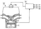
- FIG. 1 shows schematic structure of the ignition timing control apparatus concerning Embodiment 1 of this invention. It is a schematic diagram for demonstrating the content of knock learning in the ignition timing control apparatus concerning Embodiment 1 of this invention. It is a schematic diagram for demonstrating the content of knock learning in the ignition timing control apparatus concerning Embodiment 1 of this invention. It is a schematic diagram for demonstrating the effect of knock learning in the ignition timing control apparatus concerning Embodiment 1 of this invention. 4 is a flowchart of a routine executed by an electronic control unit in the ignition timing control apparatus according to the first embodiment of the present invention. It is a schematic diagram for demonstrating the content of knock learning in the ignition timing control apparatus concerning Embodiment 2 of this invention. 6 is a flowchart of a routine executed by an electronic control unit in the ignition timing control apparatus according to the second embodiment of the present invention.
- FIG. 1 is a diagram showing a schematic configuration of the ignition timing control apparatus according to the first embodiment of the present invention.
- the ignition timing control device according to the present embodiment is applied to the internal combustion engine 10.
- the internal combustion engine 10 is a 4-stroke spark ignition engine.
- the internal combustion engine 10 includes a plurality of cylinders and is an internal combustion engine for mounting on a vehicle.
- the combustion chamber 13 of the internal combustion engine 10 is provided with a spark plug 14 that ignites and burns an air-fuel mixture sucked into the combustion chamber 13.
- a knock sensor 15 is provided in the cylinder block 11 of the internal combustion engine 10. The knock sensor 15 is a sensor for detecting the occurrence of knocking accompanying combustion of the air-fuel mixture.
- the internal combustion engine 10 is provided with an electronic control unit 16 related to its operation.
- the electronic control unit 16 is a CPU that executes various controls, a ROM such as a ROM and a RAM that stores information necessary for the control, an input port for inputting a signal from the outside, and a command signal to be output to the outside. An output port and the like are provided.
- Various sensors for detecting the engine operating state are connected to the input port of the electronic control unit 16.
- a crank angle sensor 17 for detecting a crank angle which is a rotation phase of a crankshaft (not shown), and a throttle valve opening (throttle opening TA) are detected.
- a throttle sensor 19 for detecting the intake air amount and an air flow meter 20 for detecting the intake air amount are included. From the detection signal of the crank angle sensor 17, the engine speed NE can be obtained. Further, the electronic control unit 16 calculates the engine load KL based on the intake air amount, the engine speed, and the like.
- the output port of the electronic control unit 16 is connected to a drive circuit for actuators necessary for engine control, such as an igniter 14a for generating a high-voltage current necessary for ignition of the air-fuel mixture by the spark plug 14.
- the electronic control unit 16 performs various calculations based on the detection signals of the sensors, and performs engine control by executing drive control of actuators based on the calculation results.
- the electronic control unit 16 executes “knock control” that adjusts the ignition timing in accordance with the occurrence of knocking detected by the knock sensor 15.
- a control value (knock control amount) is set such that the ignition timing is retarded when the occurrence frequency of knocking is high, while the ignition timing is advanced when the occurrence frequency of knocking is low. Then, the occurrence of knocking is suppressed by setting the control target value of the ignition timing based on this knock control amount.
- a steady deviation between a knock control amount and its reference value is learned as a knock learning value. In the present embodiment, this knock learning is performed as described later.
- the electronic control unit 16 stores a base in-cylinder volume map, which will be described later, in a memory.
- the base in-cylinder volume map defines a base in-cylinder volume V base for each engine operating state.
- the engine operating state is determined by the engine speed NE and the engine load KL.
- the electronic control unit 16 can execute a process of reading one base cylinder volume V base from the base cylinder volume map using the engine speed NE and the engine load KL as input variables.
- the combustion ratio (hereinafter also referred to as “MFB”) is a value defined as an index representing the progress of combustion. Specifically, it is assumed that the combustion ratio varies in the range of 0 to 1 (or in the range of 0% to 100%). When the combustion ratio is 0 (0%), the combustion start point is indicated. When the combustion ratio is 1 (100%), the combustion end point is indicated.
- P ⁇ 0 and V ⁇ 0 are the in-cylinder pressure P and the in-cylinder volume V when the crank angle ⁇ is the predetermined combustion start timing ⁇ 0 , respectively
- P ⁇ f and V ⁇ f are The in-cylinder pressure P and the in-cylinder volume V when the crank angle ⁇ is a predetermined combustion end timing ⁇ f , respectively.
- P ⁇ and V ⁇ are the in-cylinder pressure P and the in-cylinder volume V when the crank angle ⁇ is an arbitrary value, respectively.
- ⁇ is a specific heat ratio. Since the technology relating to the combustion ratio is already known, further explanation is omitted.
- crank angle at which the combustion ratio becomes a constant value is also referred to as “predetermined combustion ratio crank angle” for convenience.
- the crank angle at which the combustion ratio is 50% will be described below as “CA50” for convenience.
- the CA50 is correlated with the ignition timing, and the CA50 moves to the retard side as the ignition timing is retarded. Assuming this relationship, the CA 50 also moves to the retard side due to the ignition retard for avoiding knocking. The closer the CA50 is to the retard side, the more the piston position at the CA50 is located below the top dead center, and the “in-cylinder volume at the CA50” becomes relatively large.
- “In-cylinder volume at CA50” is the in-cylinder volume determined from the crank angle position when the combustion ratio reaches 50%.
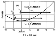
- FIG. 2 is a schematic diagram for explaining the contents of knock learning in the ignition timing control apparatus according to the first embodiment of the present invention.
- the graph shown in FIG. 2 shows the value of the in-cylinder volume determined by the piston position at each crank angle. When the crank angle that is the piston top dead center is 0 degree, the in-cylinder volume takes the minimum value, and the in-cylinder volume increases as the distance from the top dead center increases.
- FIG. 2 also shows two different ignition timings SA1 and SA2.
- FIG. 2 further schematically shows a combustion period in which combustion is performed at the ignition timing SA1 and a combustion period in which combustion is performed at the ignition timing SA2.
- the in-cylinder volume graph of FIG. 2 is compared with the arrow of the combustion period by SA1, the in-cylinder volume decreases after ignition and the in-cylinder volume becomes the minimum value at the top dead center. It is a certain period after it started to increase.
- the combustion period by SA2 is a certain period after the in-cylinder volume starts to increase from the top dead center. As a whole, it is located in the crank angle region where the cylinder volume is larger than SA1.
- the in-cylinder volume at each time point in the combustion period is relatively larger in the combustion period by SA2 than in the combustion period by SA1. That is, it can be said that the in-cylinder volume during the combustion period is increased during the combustion period of SA2.
- the in-cylinder volume during the combustion period can be relatively increased. Since SA2 has a larger in-cylinder volume during the combustion period than SA1, SA2 is in a state in which the increase in unburned gas temperature and pressure is suppressed, and the knock suppression effect is enhanced.
- the ignition timing control apparatus can perform knock learning based on such a knock suppression principle.
- “in-cylinder volume ratio” described later is learned.
- the in-cylinder volume ratio is a parameter determined from the amount of change in the in-cylinder volume. Even when the operating state changes, the learned ignition timing by the knock control means can be set to an appropriate value by reflecting the learned in-cylinder volume ratio.
- the electronic control unit 16 stores a base in-cylinder volume map.
- the base in-cylinder volume map defines a base in-cylinder volume V base for each operation state determined by the engine speed and the engine load.
- the “base in-cylinder volume V base ” is the value of the in-cylinder volume at CA50 in the combustion stroke performed at the base ignition timing SA base .
- the base ignition timing is an ignition timing set as a base value of the ignition timing of the internal combustion engine 10 and is stored in the electronic control unit 16 as an ignition timing map.
- the base ignition timing of the first operating state corresponding to the first operating state at the first engine speed NE 1 and the first engine load KL 1 is shown.
- the first base in-cylinder volume V base1 when combustion is performed in SA base1 is stored.
- the second base when corresponding to the second operation state when the second engine speed NE 2 and the second engine load KL 2, combustion is performed in the base ignition timing SA base2 of the second operating condition
- An in-cylinder volume V base1 is stored.
- n is an integer
- each of the operating states is corresponding to n operating states (first operating state, second operating state,..., Nth operating state) one by one.
- the base ignition timing (SA base1, SA base2, ⁇ SA basen) in the base cylinder volume when combustion is performed (V base1, V base2 ⁇ , V basen) are stored.
- the base cylinder volume map is created in advance and stored in the memory area of the electronic control unit 16. By using the base in-cylinder volume map, when a certain engine speed NE and engine load KL are given, one base in-cylinder volume V base corresponding to these values can be obtained.
- the ignition timing control device is roughly divided into the following “learning process” and “learned value reflection process”.
- learning process and “learned value reflection process”.
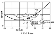
- FIG. 3 is a schematic diagram for explaining the contents of knock learning in the ignition timing control apparatus according to the first embodiment of the present invention.
- the graph shown in FIG. 3 shows the value of the in-cylinder volume for each crank angle, as in FIG. When the crank angle, which is the top dead center of the piston, is 0 degree, the in-cylinder volume takes the minimum value.
- Four points are plotted on the in-cylinder volume graph of FIG. These four points are V base1, V base2, V KC1 , V KC2.
- V base1, V base2 respectively show the base cylinder volume under different operating conditions.
- V KC1 and V KC2 are respectively referred to as “actual cylinder internal volumes”.
- This actual in-cylinder volume is the in-cylinder volume at CA50 in the combustion stroke when combustion is performed at the ignition timing after being retarded from the base ignition timing by the ignition timing control. When the ignition timing is retarded to avoid knocking, it means the ignition timing when the knocking avoidance is realized.
- V KC1 and V KC2 are actual in-cylinder volumes in different operating states.
- the learning process includes a cylinder volume detection process, a knock control process, a first cylinder volume calculation process, a second cylinder volume calculation process, and a cylinder volume ratio learning process.
- the electronic control unit 16 can execute an in-cylinder volume detection process.
- the cylinder volume at CA50 is obtained by estimation for each combustion stroke of the internal combustion engine.
- the in-cylinder volume at CA50 is obtained by estimation by executing a calculation process in the in-cylinder volume detection process.
- the CA50 is retarded when the ignition timing is retarded, and the ignition timing retard amount and the CA50 retard amount coincide with each other.
- This premise is based on the premise that the combustion period from 0% to 50% is constant regardless of the ignition timing. According to this premise, first, the value of the in-cylinder volume corresponding to CA50 when combustion is performed at the base ignition timing, that is, the base in-cylinder volume is obtained. If the retardation amount with respect to the base ignition timing is determined, the retardation amount of the CA 50 is determined according to the retardation amount.
- the base in-cylinder volume is increased by the retard amount in accordance with the relationship between the piston position determined from the crank angle and the in-cylinder volume. Can be calculated. Also in the present embodiment, based on this assumption, an in-cylinder volume detection processing program for calculating the in-cylinder volume at the CA 50 reflecting the ignition timing retardation amount is created, and the electronic control unit 16 executes this process. To do.
- the electronic control unit 16 executes a knock control process.
- the knock control process is a process for performing ignition timing control so that knocking of the internal combustion engine 10 is not more than a predetermined level. Specifically, the corrected ignition timing is obtained by correcting (retarding or advancing) the base ignition timing so that knocking detected by the knock sensor 15 is below an allowable level. This process avoids knocking.
- the electronic control unit 16 performs a first in-cylinder volume calculation process.
- the first in-cylinder volume calculation process calculates a first base in-cylinder volume V base1 also shown in FIG.
- the first base in-cylinder volume V base1 is combustion performed at the first base ignition timing SA base1 when the engine operating state is in the first operating state (the first engine speed NE 1 and the first engine load KL 1 ). This is the in-cylinder volume at CA50 in the stroke.
- the electronic control unit 16 calculates a value corresponding to the engine speed NE 1 and the engine load KL 1 among the plurality of base cylinder volume values stored in the base cylinder volume map. Read as internal volume Vbase1 .
- the electronic control unit 16 executes a second cylinder volume calculation process.
- the second cylinder volume calculation process calculates the actual cylinder volume V KC1 also shown in FIG.
- the actual in-cylinder volume V KC1 is calculated at the CA50 in the combustion stroke performed at the ignition timing after the ignition timing control by the knock control is performed after the engine operation state is in the first operation state. This is the cylinder volume.
- the ignition timing is corrected (retarded or advanced) based on the detection value of the knock sensor 15 so that the knocking is below a predetermined level.
- a certain correction amount ⁇ SA is added to the base ignition timing SA base .
- the CA50 during the combustion stroke is determined. Due to the engine structure, the piston position is determined from the crank angle, and as a result the in-cylinder volume is determined. If the CA50 value is determined, the value of one in-cylinder volume is determined accordingly.
- the in-cylinder volume is calculated from such a series of relationships between the ignition timing, the combustion ratio, the crank angle, and the in-cylinder volume.
- a function that uniquely defines the relationship between the ignition timing and the in-cylinder volume is stored in the electronic control unit 16 in the form of a mathematical expression or a map.
- the electronic control unit 16 executes a process of calculating V KC1 from the ignition timing correction amount (retard amount) according to a mathematical expression or map representing this function.
- the electronic control unit 16 performs an in-cylinder volume ratio learning process.
- the cylinder volume ratio learning process calculates the cylinder volume ratio and stores it as a learning value.
- the in-cylinder volume ratio is the difference obtained by subtracting the “in-cylinder volume calculated by the second in-cylinder volume calculation process” from the “in-cylinder volume calculated by the first in-cylinder volume calculation process”. It is a value divided by the “in-cylinder volume calculated by the dispensing process”.
- the in-cylinder volume ratio to be stored as the learning value is expressed by the following equation.
- the electronic control unit 16 executes a learning value storage process for storing the value of ⁇ V / V base1 as a knock learning value in a predetermined memory area.
- the learning value reflecting process is for using the learning value acquired by the learning process described above at the time of knock control under a different driving state (referred to as “second driving state” in the present embodiment). It is a step.
- the learned value reflecting process includes a third in-cylinder volume calculating process and a learning ignition timing setting process.
- the electronic control unit 16 executes a third in-cylinder volume calculation process.
- the third in-cylinder volume calculation process calculates the second base in-cylinder volume V base2 also shown in FIG.
- the second base cylinder volume V base2 the second base ignition timing SA when the engine operating condition is in the second operating condition different from the first operating state (second engine rotational speed NE2 and a second engine load KL2) in the combustion stroke to be performed by base2, a cylinder volume of at CA50.
- the electronic control unit 16 reads the value of the base cylinder volume determined from the second engine speed NE2 and the second engine load KL2 from the base cylinder volume map, and this is read as the second base cylinder volume. Let Vbase2 .
- the electronic control unit 16 executes a setting process for setting the “learning ignition timing”.
- the “learning ignition timing” is an ignition timing as an initial value when the ignition timing control by the knock control process is performed when the engine operating state is in the second operating state. That is, in the knock control process, the ignition timing control is started with the learning ignition timing as an initial value, and further correction (generally, retarding) is performed on the initial value.
- this setting process sets an initial value of a correction amount ( ⁇ SA) to be added to the base ignition timing SA base , and this correction amount is used to calculate the learning ignition timing.
- ⁇ SA correction amount
- the learning ignition timing is set so that the actual in-cylinder volume V KC2 increases as the learning value increases.
- the actual in-cylinder volume V KC2 is the actual in-cylinder volume in the combustion stroke at the learning ignition timing, and is also shown in FIG.
- “learning ignition timing at which actual cylinder volume V KC2 is achieved” is set. That is, as shown in FIG. 3, the V KC2, the V base2 within second base cylinder volume is an enlarged cylinder volume by increment ⁇ V' with.
- this in-cylinder volume expansion amount ⁇ V ′ is calculated using a learning value as follows.
- ⁇ V' V base2 ⁇ ( ⁇ V / V base1) ⁇ (4)
- the ignition timing retard amount with respect to the base ignition timing is calculated so that a learning ignition timing at which the actual in-cylinder volume V KC2 is achieved is obtained.
- the present embodiment introduces the premise that the ignition timing retardation amount and the CA50 retardation amount coincide. According to this assumption, in the present embodiment, as the ignition timing retard amount and CA50 retard amount matches the actual cylinder volume V KC2 at present combustion stroke by adding ⁇ V' the "V base2 The ignition timing retardation amount is calculated so as to be “in-cylinder volume”.
- the learning result by the above series of processes is used for ignition timing control. That is, in the knock control, the ignition timing control is started after the initial value of the ignition timing is set to the learning ignition timing.
- the learning process and the learning value reflection process are repeated again. That is, a series of processes such as correction of the base ignition timing and learning of the in-cylinder volume ratio are performed so that knocking detected by the knock sensor 15 is below the allowable level.
- the portion relating to the first operating state is read as “the operating state at the time of the previous combustion stroke”, and the portion relating to the second operating state is referred to as “the time after the combustion stroke. "Operating state at time of”.
- the same process may be executed each time a combustion stroke occurs with the operation of the internal combustion engine 10.
- a plurality of operating states can be dealt with by having one cylinder volume ratio learning value. That is, the learning value is updated while the learning process and the learning value reflection process are repeated as the operation time of the internal combustion engine 10 elapses. Using the latest updated learning value, the amount of retardation with respect to the base ignition timing is calculated by using the above equation (4) so that a learning ignition timing at which an appropriate actual cylinder volume is achieved is obtained. can do. Therefore, the learning value can be unified.
- the knock learning technique of the ignition timing control device uses a single in-cylinder volume ratio learning value in a consistent learning method even in a plurality of different operating states, and uses the knock learning value. Can be set appropriately.
- FIG. 4 is a schematic diagram for explaining the operational effects of knock learning in the ignition timing control apparatus according to the first embodiment of the present invention.
- the vertical axis in FIG. 4 represents “in-cylinder volume change rate”, which is a value of (dV / d ⁇ ) / V.
- V is the in-cylinder volume
- dV / d ⁇ is the change in the in-cylinder volume per degree (deg) of the crank angle.
- the knock suppression effect per crank angle turns from increasing to decreasing at a predetermined crank angle.
- FIG. 4 it can be seen that the in-cylinder volume change rate turns from increasing to decreasing at a certain crank angle (crank angle of 30 degrees in FIG. 4).
- the in-cylinder volume ratio is used as a learning value, and the ignition timing at the time of knock avoidance is determined using the learned value.
- the in-cylinder volume change rate is the same, the unburned gas temperature and pressure change rate are also the same. Based on this relationship, by making the in-cylinder volume change rate accompanying the ignition timing retardation constant, the same knock suppression effect can be obtained every time even under different operating conditions.
- multiplication of the same learning value is performed every time according to the above equation (4). Then, the ignition timing retardation amount is determined so that the actual in-cylinder volume determined from the calculation result is realized. Thereby, it is possible to make the knock suppression effect uniform every time.
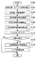
- FIG. 5 is a flowchart of a routine executed by the electronic control unit 16 in the ignition timing control apparatus according to the first embodiment of the present invention.
- the electronic control unit 16 repeats this routine during the operation of the internal combustion engine 10 and executes it every combustion stroke (for each combustion cycle).
- the routine of FIG. 5 is executed again from the state where the routine of FIG. 5 has already been executed once and the learning value has been obtained once will be described.
- step S100 the electronic control unit 16 executes a process of detecting the vehicle state and the engine state. In this step, the following three detection processes are performed.
- the first detection process is a process for detecting the speed of the vehicle.
- the speed detection is realized by the electronic control unit 16 receiving an output signal from the speedometer of the vehicle.
- the second detection process is a process for detecting a driver request for the vehicle.
- the detection of the driver request specifically includes detection of the accelerator opening and detection of the shift position.
- the electronic control unit 16 detects these signals by receiving signals from an accelerator opening sensor and a shift position detection circuit (not shown).
- the third detection process is a process for detecting the engine state of the internal combustion engine 10.
- the engine state includes engine cooling water temperature, engine speed, intake air amount, compression ratio, and the like. These detections are performed when the electronic control unit 16 obtains outputs of various sensors mounted on the internal combustion engine such as an engine water temperature sensor, a crank position sensor, an air flow meter, and the like.
- step S102 the electronic control unit 16 performs fuel injection amount control based on the detected intake air amount. More specifically, in this step, engine control other than the ignition timing control is performed using the detection result in step S100. Since the engine control performed here may use various known engine control techniques, detailed description thereof is omitted.
- step S104 the electronic control unit 16 executes processing for calculating the cylinder volume ratio correction value.
- This step is a step of calculating the ignition timing correction value required in accordance with the change in the environment such as the intake air temperature, the outside air temperature, and the supercharging pressure in units of in-cylinder volume ratio ⁇ V / V. Note that the method of calculating the cylinder volume ratio correction value described here is different from the calculation content described in the “learning process” according to the first embodiment.
- the electronic control unit 16 stores a correction value calculation program for calculating the in-cylinder volume ratio correction value ( ⁇ V / V) dst corresponding to the intake air temperature, the outside air temperature and other disturbances.
- In-cylinder volume ratio correction value ( ⁇ V / V) dst is a value that indicates how much the ignition timing is delayed with respect to a change amount (for example, change temperature) when an environment such as intake air temperature, outside air temperature, supercharging pressure, or the like changes. It is an index value indicating whether or not to make a corner.
- the relationship between the in-cylinder volume ratio correction value ( ⁇ V / V) dst and the “disturbance change amount” is created in advance in the form of a correction value formula or a correction value map. Is stored in the electronic control unit 16 in advance.
- An in-cylinder volume ratio correction value ( ⁇ V / V) dst is calculated by inputting the amount of change in disturbance to the correction value calculation program.
- the amount of change in disturbance is specifically the amount of intake air temperature change based on the output of an intake air temperature sensor (not shown), the amount of outside air temperature change based on the output of an outside air temperature sensor (not shown), and the output of an intake pressure sensor (not shown). Assume the amount of change in supercharging pressure.
- a plurality of the above correction value formulas and correction value maps are created for each type of disturbance or for each operating state.
- the cylinder volume ratio correction value ( ⁇ V / V) dst calculated in step S104 is used together with the cylinder volume ratio learning value according to the present embodiment in subsequent steps. Thereby, the in-cylinder volume ratio to be finally realized is calculated.
- the electronic control unit 16 executes a process of calculating the KCS ignition timing learning amount (step S106). And the electronic control unit 16 performs the process which reflects the correction amount by an ignition timing learning value (step S108). In these steps, the electronic control unit 16 carries out the contents of the “learning ignition timing setting process” in the “learning value reflection process” described above.
- step S106 the electronic control unit 16 executes a process of reading the knock learning value learned by the “learning process” described above.
- the previous knock learning is performed in the first operating state, and the value of ⁇ V / V base1 is stored in the knock learning value.
- the in-cylinder volume ratio correction value ( ⁇ V / V) dst and the knock learning value ⁇ V / V base1 are added together to calculate the integrated in-cylinder volume ratio ( ⁇ V / V) Total .
- This “summation” means a calculation for reflecting a plurality of correction values in the ignition timing control.
- a value obtained by collecting correction values and learning values into one numerical value is obtained by multiplying a value of (V + ⁇ V) / V.
- a specific numerical value will be described as an example.
- knock learning value ⁇ V / V base1 is 0.2
- an integrated value of 1.32 is obtained.
- the value of 1.32 is converted into a plurality of correction values and learning values (that is, in-cylinder volume ratio correction value ( ⁇ V / V) dst and knock learning value ⁇ V / V base1 ). It shall be handled as an aggregated (summed) value.
- the electronic control unit 16 calculates the in-cylinder volume expansion amount ⁇ V 2 ′ according to the following mathematical formula (6) using the integrated in-cylinder volume ratio ( ⁇ V / V) Total .
- ⁇ V 2 ′ V base2 ⁇ ( ⁇ V / V) Total (6)
- the content of the calculation of Expression (6) is similar to Expression (4) related to the “learning value reflection process” described above.
- the current operation state is the second operation state, and the in-cylinder volume expansion amount ⁇ V 2 ′ with respect to the base in-cylinder volume V base2 is calculated.
- the electronic control unit 16 calculates the ignition timing retard amount with respect to the base ignition timing SA base2 .
- the ignition timing retard quantity as [Delta] V 2 'worth only this base cylinder volume V base2 cylinder volume from expanding, a retard amount calculated with respect to the base ignition timing SA base2.
- the ignition timing retard amount is a retard amount calculated with respect to the base ignition timing SA base2 so that a learning ignition timing at which the actual in-cylinder volume V KC2 is achieved is obtained.
- step S110 the electronic control unit 16 executes an ignition timing feedback control process based on the output of the knock sensor 15 (step S110). Note that at the stage of reaching this step, it is assumed that the combustion stroke is being performed in the internal combustion engine 10 and that knocking can be detected by the knock sensor 15. In this step, the ignition timing control is performed so that the knocking is below the allowable level by the electronic control unit 16 executing the knock control. The initial value of this knock control is the ignition timing (learning ignition timing) reflected in step S108.
- step S112 the electronic control unit 16 executes a process of determining whether or not the feedback correction amount is larger than a predetermined value.
- Changes in intake air temperature, intake pipe pressure, in-cylinder deposit accumulation, octane number, and other environmental conditions are disturbances, but the learning value may not be appropriate due to the change in disturbances. Therefore, in this step, it is determined whether or not the feedback correction amount in step S110, that is, the ignition timing retardation amount by knock control, deviates from the learning ignition timing by a predetermined value or more. This makes it possible to evaluate whether the current learning value is appropriate. If it is determined in this step that the feedback correction amount is larger than the predetermined value, it can be determined that the current learning value is no longer appropriate and an update process described later is necessary.
- step S112 If it is not determined in step S112 that the feedback correction amount is greater than the predetermined value, the current routine ends without updating the knock learning value. Then, the routine of FIG. 5 is executed again in the next combustion stroke.
- step S112 If it is determined in step S112 that the feedback correction amount is greater than the predetermined value, the electronic control unit 16 executes a process of calculating a time when the 50% combustion ratio is reached (step S114). Then, the electronic control unit 16 calculates ⁇ V / V base2, that is, the in-cylinder volume ratio, and executes a process of updating the learning value with the calculated value (step S116). That is, in the series of processes in steps S114 and S116, the electronic control unit 16 performs the in-cylinder volume detection process, the first in-cylinder volume calculation process, the second in-cylinder volume calculation process, and the “learning process” described above, and The contents of the cylinder volume ratio learning process are executed.
- step S114 the time (crank angle) at which the combustion ratio reaches 50% is calculated.
- the actual in-cylinder volume V KCX is calculated.
- the actual in-cylinder volume V KCX is the actual in-cylinder volume at CA50 after the ignition timing feedback control in step S112.
- the actual in-cylinder volume V KCX is realized by the electronic control unit 16 executing the second in-cylinder volume calculation process related to the “learning process” described above.
- step S108 the determination routine in step S112 indicates that the ignition timing is inappropriate. Therefore, it is considered that the ignition timing determined by the ignition timing feedback control process in step S110 is significantly different from the ignition timing that realizes the actual in-cylinder volume V KC2 . Therefore, the actual in-cylinder volume V KCX is different from the actual in-cylinder volume V KC2 .
- the base cylinder volume is read from the base cylinder volume map.
- V base2 is read from the base cylinder volume map. This process corresponds to the first in-cylinder volume calculation process in the aforementioned “learning process”.
- step S116 using the actual cylinder volume V KCX and the base cylinder volume V base2, according to the following equation, cylinder volume ratio is calculated.
- This process corresponds to the cylinder volume ratio learning process in the “learning process” described above.
- In-cylinder volume ratio ⁇ V / V base2 (7)
- ⁇ V V base2 -V KCX ⁇ ( 8)
- the electronic control unit 16 executes a learning value storing process for storing the value of ⁇ V / V base2 in a predetermined memory area as a knock learning value. Thereby, the update of the knock learning value is completed.
- the in-cylinder volume determined by the crank angle at which the combustion ratio is 50% is used for knock learning.
- the “crank angle at which the combustion ratio is 50%”, that is, CA50 plays a role as “a crank angle representing combustion”. This is because it is possible to detect whether the combustion period is on the advance side or the retard side as a whole by looking at the relative positional relationship of CA50.
- the present invention is not limited to this, and an in-cylinder volume determined by a crank angle at which the combustion ratio is other than 50% may be used.
- the combustion ratio is any point from 0 to 100%, specifically, any one of the combustion ratios such as 10%, 20%, 30%,..., 60%, 70%, 80%, etc.
- One may be used as a predetermined combustion ratio instead of the 50% combustion ratio.
- the 10% increments are merely examples.
- the crank angle corresponding to each of these combustion ratios is written as CA10, CA20, CA30,..., CA60, CA70, CA80 according to the same rules as CA50.
- the in-cylinder volume determined by the selected crank angle at the desired combustion ratio may be used as a learning parameter for knock learning according to the first embodiment.
- the crank angle at which the predetermined combustion ratio is obtained is abbreviated as “predetermined combustion ratio crank angle”.
- CA50 is preferable in that it can represent the entire combustion in a well-balanced manner compared to CA10 and CA20 in the first half of combustion or CA70 and CA80 in the second half of combustion.
- the ignition timing control apparatus In the second half of the combustion, that is, the period when the combustion ratio is later than 50%, the unburned gas temperature and pressure become higher, and the contribution to the occurrence of knocking is large. Therefore, with emphasis on the latter half of the combustion, that is, for example, CA60, CA70, etc. may be selected as the predetermined combustion ratio crank angle instead of CA50, and the ignition timing control apparatus according to the first embodiment may be constructed.
- the in-cylinder volume at CA50 is estimated by the in-cylinder volume detection process.
- the present invention is not limited to this, and direct detection using an in-cylinder pressure sensor may be performed. That is, an in-cylinder pressure sensor may be installed in the internal combustion engine 10 and the pressure in the cylinder may be directly sensed to calculate the combustion ratio according to Equation (1). A crank angle at a 50% combustion rate may be specified from the calculated combustion rate, and the in-cylinder volume may be calculated from the specified crank angle. As described above, the in-cylinder volume at the CA 50 may be obtained using the detection result of the in-cylinder pressure based on the in-cylinder pressure sensor.
- FIG. [Configuration of Apparatus According to Second Embodiment]
- the hardware configuration of the ignition timing control device according to the second embodiment is the same as the device configuration of the first embodiment (configuration shown in FIG. 1). Therefore, illustration of the hardware configuration is omitted.
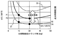
- FIG. 6 is a schematic diagram for explaining the contents of knock learning in the ignition timing control apparatus according to the second embodiment of the present invention.
- the characteristic curve indicated by the bold line with the symbol d ⁇ / (dV / V) is also referred to as “base characteristic curve”.
- This base characteristic curve indicates the crank angle change amount per unit cylinder volume change rate.
- the in-cylinder volume change rate dV / V is a value obtained by dividing the minute in-cylinder volume change dV by the in-cylinder volume V.
- the base characteristic curve shows the crank angle change amount d ⁇ necessary to change the in-cylinder volume so that the in-cylinder volume change rate dV / V becomes 1 for a plurality of operating states with different CA50. is there.
- This base characteristic curve is a theoretical value calculated from the crank diameter and the connecting rod length, which are geometric dimensions of the internal combustion engine 10.
- thin characteristic curves S1 and S2 in FIG. 6 each represent an ignition timing correction amount.
- the ignition timing correction amount is a retard amount with respect to the base ignition timing.
- the knock learning according to the second embodiment will be schematically described.
- “the amount of change in each crank per volume change rate” and the “ignition timing correction amount” are proportional.
- “change amount of each crank per volume change rate” may be described as d ⁇ / (dV / V)).
- FIG. 6 is a diagram created based on such a premise, and d ⁇ / (dV / V) and the ignition timing correction amount are both shown on the vertical axis of a graph having the same scale.
- the base characteristic curve is calculated so that “the whole is equal to the learning coefficient”.
- characteristic curves S1 and S2 are obtained, and the ignition timing correction amount is calculated using the characteristic curves S1 and S2.
- a characteristic curve S1 obtained by multiplying the base characteristic curve as a whole by the learning coefficient is obtained.
- a value determined from this characteristic curve S1 is set as the ignition timing retard amount for each crank angle of CA50 in each operating state.
- the ignition timing control apparatus finally calculates the ignition timing correction amount using the base characteristic curve and the learning coefficient to be multiplied by the base characteristic curve.
- the electronic control unit 16 stores a map that defines the base characteristic curve, and also includes a storage area that enables writing and reading of learning coefficients.
- the electronic control unit 16 performs the ignition timing feedback control so that the knock level is below the allowable level based on the knock control, that is, the output of the knock sensor 15.
- knock control is performed in an operating state in which the CA50 is located at a crank angle of 15 degrees, and the result of this knock control (ignition timing retard amount) is represented on the map shown in FIG. 6, the result of that knock control Assuming that the ignition timing retardation amount is P2 (° CA).
- the electronic control unit 16 executes a process of storing the value of P2 / P1 as a learning coefficient.
- the crank angle change amount of P1 (° CA) is theoretically necessary, whereas the actual knock control results.
- the ignition timing retardation obtained as follows is P2 (° CA) which is smaller than this. Accordingly, the value P2 / P1 represents the in-cylinder volume change rate changed by the previous knock control.
- the learning coefficient P2 / P1 described above represents the in-cylinder volume change rate when the in-cylinder volume changes due to the ignition timing being retarded by the previous knock control.
- In-cylinder volume expansion at the same in-cylinder volume change rate means that the in-cylinder volume is increased at CA50 so that the in-cylinder volume change rate takes a value of 0.4.
- the value of d ⁇ / (dV / V) is P3 (° CA). This means that the ignition timing needs to be changed by P3 (° CA) in order to obtain an in-cylinder volume change rate (dV / V) of 1 in an operating state in which the CA50 has a crank angle of 30 degrees. .
- the in-cylinder volume change rate can be set to 1 if the crank angle is changed by 4 ° CA.
- the electronic control unit 16 multiplies the learning coefficient P2 / P1 and the value of P3 described above. Based on the in-cylinder volume change rate obtained by this calculation, an appropriate ignition timing retard amount at the present time in an operating state in which the CA50 is a crank angle of 30 degrees is calculated.
- the electronic control unit 16 sets the value of P4 (° CA) as the ignition timing retard amount. As a result, knock learning can be performed in another driving state, and the ignition timing of the current driving state can be set appropriately using the learning result.
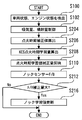
- FIG. 7 is a flowchart of a routine executed by the electronic control unit 16 in the ignition timing control apparatus according to the second embodiment of the present invention.
- the electronic control unit 16 repeats this routine during the operation of the internal combustion engine 10 and executes it every combustion stroke (each combustion cycle).
- the routine of FIG. 7 is executed again from the state where the routine of FIG. 7 has already been executed once and the learning coefficient has been obtained once.
- the electronic control unit 16 executes the processes of steps S100 and S102 in the same manner as the specific process of the first embodiment shown in FIG.
- step S206 the electronic control unit 16 executes a process for calculating an ignition timing correction value.
- the process of step S206 is a process of calculating the ignition timing correction amount as a crank angle for disturbances such as intake air temperature that can be individually determined. It should be noted that the relationship between the amount of each disturbance (intake temperature change amount, etc.) and the ignition timing correction amount is stored in advance in the electronic control unit 16 in the form of a map or a calculation formula.
- the ignition timing correction amount (° CA) is calculated as a retard amount or an advance amount.
- step S206 the electronic control unit 16 executes a process of calculating the KCS ignition timing learning amount.
- the electronic control unit 16 performs the above-described “coefficient use process”.
- step S206 the electronic control unit 16 executes a process of reading the learning coefficient K learned by the above-described “coefficient learning process” from a predetermined storage area of the memory.
- the previous knock learning is “an operating state in which the CA50 has a crank angle of 15 degrees (that is, engine speed NE 21 , certain engine load KL 21 , certain ignition timing SA 21 )”. It is assumed that the value of P2 / P1 is stored in the learning coefficient K. Note that the specific numerical value of the learning coefficient K exemplified in the above description is 0.4.
- the electronic control unit 16 executes a process for calculating the ignition timing retardation amount necessary for knock suppression using the learning coefficient K according to the equation (9) described above.
- the current operation state is “an operation state in which the CA50 has a crank angle of 30 degrees”.
- the engine speed NE 22 , the engine load KL 22 , and the ignition timing SA 22 are assumed.
- the ignition timing retardation amount P4 (° CA) is calculated as (P2 / P1) ⁇ P3 by the calculation according to Equation (9).
- the ignition timing retardation amount P4 can be calculated so as to obtain the same knock suppression effect as the knock control performed in the driving state at the time of learning coefficient acquisition.
- the specific numerical value exemplified in the above description is 1.6 (° CA).
- the ignition timing retardation amount and the CA50 retardation amount coincide with each other.
- step S206 a process of adding the ignition timing correction amount in step S206 and the ignition timing retardation amount P4 obtained from the learning coefficient K described above is executed. Thereby, the final ignition timing correction amount is calculated.
- the electronic control unit 16 executes processing for reflecting the ignition timing correction amount calculated in step S206 in the ignition timing (step S208).
- the electronic control unit 16 only a series of ignition timing retard amount obtained by the process described above is carried out the ignition timing control to retard the ignition timing for the current ignition timing SA 22.
- the electronic control unit 16 executes a feedback control process for the ignition timing based on the output of the knock sensor 15 (step S110). Note that at the stage of reaching this step, it is assumed that the combustion stroke is being performed in the internal combustion engine 10 and that knocking can be detected by the knock sensor 15. In this step, the ignition timing control is performed so that the knocking is below the allowable level by the electronic control unit 16 executing the knock control.
- the initial value of this knock control is the ignition timing (learning ignition timing) set in step S208 above.
- step S212 the electronic control unit 16 executes a process of determining whether or not the feedback correction amount is larger than a predetermined value.
- the processing contents are the same as in step S212 of the first embodiment, and it is determined whether or not the ignition timing feedback correction amount, that is, the ignition timing retardation amount by knock control, deviates from the learning ignition timing by a predetermined value or more. Is done.
- step S212 If it is not determined in step S212 that the feedback correction amount is greater than the predetermined value, the current routine ends without the learning coefficient K being updated. Then, the routine of FIG. 7 is executed again in the next combustion stroke.
- step S212 If it is determined in step S212 that the feedback correction amount is larger than the predetermined value, the electronic control unit 16 calculates a learning coefficient K and executes a process of updating the learning coefficient with the calculated value (step S216). ).
- step S216 the learning coefficient K is calculated according to the above-described “coefficient learning process”. That is, the ignition timing retardation amount P ′ obtained as a result of the current knock control is divided by P3.
- the value P ′ / P3 is a newly learned learning coefficient K, and the electronic control unit 16 executes a storage process for storing the P ′ / P3 in a predetermined memory area. Thereby, the update of the learning coefficient K is completed.
Landscapes
- Engineering & Computer Science (AREA)
- Chemical & Material Sciences (AREA)
- Combustion & Propulsion (AREA)
- Mechanical Engineering (AREA)
- General Engineering & Computer Science (AREA)
- Signal Processing (AREA)
- Electrical Control Of Ignition Timing (AREA)
- Combined Controls Of Internal Combustion Engines (AREA)
Abstract
Description
ノック制御手段は、内燃機関のノッキングを所定レベル以下とするように点火時期制御を実施する。
第1筒内容積算出手段は、機関運転状態が第1運転状態にあるときに第1ベース点火時期で実施される燃焼行程における、所定燃焼割合クランク角での筒内容積を算出する。この所定燃焼割合クランク角は、燃焼割合が50%となるときのクランク角とすることが好ましい。
第2筒内容積算出手段は、機関運転状態が前記第1運転状態にあるときに前記ノック制御手段での当該点火時期制御が実施された点火時期で実施される燃焼行程における、前記所定燃焼割合クランク角での筒内容積を算出する。
筒内容積率学習手段は、筒内容積率を算出し、算出した筒内容積率を学習値として記憶する。筒内容積率とは、前記第1筒内容積算出手段で算出した筒内容積から前記第2筒内容積算出手段で算出した筒内容積を減算した差分を前記第1筒内容積算出手段で算出した筒内容積で除算した値である。
第3筒内容積算出手段は、機関運転状態が前記第1運転状態と異なる第2運転状態にあるときに第2ベース点火時期で実施される燃焼行程における、前記所定燃焼割合クランク角での筒内容積を算出する。
設定手段は、学習点火時期を設定する。学習点火時期とは、機関運転状態が前記第2の運転状態にあるときに前記ノック制御手段による点火時期制御を実施するときの初期値としての点火時期である。この設定手段は、前記学習値が大きいほど、前記学習点火時期で実施される燃焼行程における前記所定燃焼割合クランク角での筒内容積が大きくなるように、前記学習点火時期を設定する。
前記設定手段は、前記学習点火時期で実施される燃焼行程における前記所定燃焼割合クランク角での筒内容積が、前記第3筒内容積算出手段で算出した筒内容積に前記学習値を積算した積算値分だけ前記第3筒内容積算出手段で算出した筒内容積から変化するように、前記学習点火時期を設定するものである。
ノック制御手段は、内燃機関のノッキングを所定レベル以下とするように点火時期制御を実施する。
記憶手段は、単位筒内容積変化率あたりのクランク角変化量とクランク角との間の関係を定めた特性を記憶したものである。
第1クランク角取得手段は、機関運転状態が第1運転状態にあるときの燃焼行程における、所定燃焼割合クランク角を検知又は推定により求める。
第1特性値算出手段は、前記特性に従って、前記第1クランク角取得手段で求めた前記所定燃焼割合クランク角における、単位筒内容積変化率あたりのクランク角変化量の値を、第1特性値として算出する。
学習手段は、前記第1運転状態で前記ノック制御手段による点火時期制御が実施された場合に、この点火時期制御により得られた遅角量と前記第1特性値との比を、学習値として記憶する。
第2クランク角取得手段は、機関運転状態が前記第1運転状態と異なる第2運転状態にあるときの燃焼行程における、前記所定燃焼割合クランク角を検知又は推定により求める。
第2特性値算出手段は、前記特性に従って、前記第2クランク角取得手段で求めた前記所定燃焼割合クランク角における、単位筒内容積変化率あたりのクランク角変化量の値を、第2特性値として算出する。
設定手段は、機関運転状態が前記第2運転状態にあるときに前記ノック制御手段による点火時期制御を実施するときの点火時期遅角量の初期値である学習遅角量を設定する設定手段である。設定手段は、前記第2特性値に対して前記学習値を乗じた値に基づいて、前記学習遅角量を設定する。
[実施の形態1にかかる装置の構成]
図1は、本発明の実施の形態1にかかる点火時期制御装置の概略構成を示す図である。本実施の形態にかかる点火時期制御装置は、内燃機関10に適用される。内燃機関10は4ストローク式の火花点火式エンジンである。図示を省略するが、内燃機関10は、複数の気筒を備えており、車両搭載用の内燃機関である。
(点火遅角によるノック抑制効果の原理)
本願発明者の知見によれば、点火遅角によるノック抑制効果の原理は、「点火時期が遅角されて燃焼期間が遅角側に移動すると、燃焼期間の筒内容積が拡大し、その結果、未燃ガス温度および圧力の上昇が抑制される」というものである。本実施の形態にかかる点火時期制御装置によれば、この原理にもとづくノック学習が可能である。
MFB=(PθVθ κ-Pθ0Vθ0 κ)/(PθfVθf κ-Pθ0Vθ0 κ)・・・(1)
但し、上記(1)式において、Pθ0およびVθ0は、それぞれクランク角度θが所定の燃焼開始時期θ0である場合の筒内圧Pおよび筒内容積Vであり、PθfおよびVθfは、それぞれクランク角度θが所定の燃焼終了時期θfである場合の筒内圧Pおよび筒内容積Vである。また、PθおよびVθは、それぞれクランク角度θが任意の値である場合の筒内圧Pおよび筒内容積Vである。κは、比熱比である。燃焼割合に関する技術は既に公知であるため、これ以上の説明は省略する。
また、図2には、2つの異なる点火時期SA1およびSA2が記載されている。図2には、さらに、点火時期SA1で燃焼が実施された燃焼期間と、点火時期SA2で燃焼が実施されたときの燃焼期間とが、それぞれ模式的に示されている。
本実施の形態にかかる点火時期制御装置の動作の前提として、先ずはじめに、電子制御ユニット16がベース筒内容積マップを記憶している。ベース筒内容積マップには、機関回転数および機関負荷で定まる運転状態ごとに、ベース筒内容積Vbaseが定められている。本実施の形態では、「ベース筒内容積Vbase」とは、ベース点火時期SAbaseで実施した燃焼行程における、CA50での筒内容積の値のことである。ベース点火時期は、内燃機関10の点火時期のベース値として設定された点火時期であり、電子制御ユニット16に点火時期マップとして記憶されている。
学習処理には、筒内容積検出処理、ノック制御処理、第1筒内容積算出処理、第2筒内容積算出処理、および筒内容積率学習処理が含まれている。
第1ベース筒内容積Vbase1は、機関運転状態が第1運転状態(第1機関回転数NE1および第1機関負荷KL1)にあるときに第1ベース点火時期SAbase1で実施される燃焼行程における、CA50での筒内容積である。
本実施の形態では、電子制御ユニット16が、ベース筒内容積マップに記憶された複数個のベース筒内容積値のうち、機関回転数NE1と機関負荷KL1に対応する値を、ベース筒内容積Vbase1として読み出す。
この実筒内容積VKC1は、機関運転状態が第1運転状態にあるときにノック制御による点火時期制御が実施された後、その制御後の点火時期で実施された燃焼行程における、CA50での筒内容積である。
「筒内容積率」=ΔV/Vbase1 ・・・(2)
ΔV=Vbase1-VKC1 ・・・(3)
本実施の形態では、電子制御ユニット16が、このΔV/Vbase1の値をノック学習値として所定メモリ領域に記憶する学習値記憶処理を実行する。
学習値反映処理は、上記の学習処理により獲得された学習値を、その後、異なる運転状態下(本実施の形態では、「第2運転状態」と称している)におけるノック制御時に活用するためのステップである。学習値反映処理には、第3筒内容積算出処理、および学習点火時期の設定処理が含まれている。
本実施の形態では、電子制御ユニット16が、ベース筒内容積マップから、第2機関回転数NE2および第2機関負荷KL2から決まるベース筒内容積の値を読み出し、これを第2ベース筒内容積Vbase2とする。
ΔV´=Vbase2×(ΔV/Vbase1) ・・・(4)
そして、このΔV´分だけVbase2から筒内容積が拡大するように、ベース点火時期に対する点火時期遅角量を算出する。すなわち、実筒内容積VKC2が達成される学習点火時期が得られるように、ベース点火時期に対する点火時期遅角量を算出する。
図4の縦軸は、「筒内容積変化率」を表しており、(dV/dθ)/Vの値である。Vは筒内容積であり、dV/dθは、クランク角の1度(deg)あたりの筒内容積の変化分である。
図5は、本発明の実施の形態1にかかる点火時期制御装置において、電子制御ユニット16が実行するルーチンのフローチャートである。電子制御ユニット16は、このルーチンを、内燃機関10の運転中に、繰り返し、燃焼行程(燃焼サイクルごと)ごとに実行する。以下では、既に図5のルーチンが一度実行されて学習値が一度得られた状態から、再度、図5のルーチンが実行される場合を説明するものとする。
第2検出処理は、その車両に対するドライバー要求を検出する処理である。ドライバー要求の検出は、具体的には、アクセル開度の検出およびシフトポジションの検出を含む。電子制御ユニット16が図示しないアクセル開度センサやシフト位置検出回路からの信号を受けることにより、これらの検出が実施される。
第3検出処理は、内燃機関10のエンジン状態を検出する処理である。エンジン状態には、エンジン冷却水温、機関回転数、吸入空気量、圧縮比などが含まれる。これらの検出は、エンジン水温センサやクランクポジションセンサ、エアフローメータ等といった、内燃機関に搭載される各種センサの出力を電子制御ユニット16が得ることにより実施される。
このステップでは、より具体的には、ステップS100の検出結果を利用して、点火時期制御以外のエンジン制御が実施される。ここで実施されるエンジン制御は各種公知のエンジン制御技術を利用すればよいため、詳細な説明は省略する。
1+(ΔV/V)Total=(1+ΔV/Vbase1)×(1+(ΔV/V)dst) ・・・(5)
この数式(5)から、(ΔV/V)dstが0.1でありΔV/Vbase1が0.2である場合には、(ΔV/V)Totalが0.32となることが導かれる。
本実施の形態のように乗算を行うようにし、筒内容積率補正値やノック学習値の値を単純に加算しない理由は、これらの値はそれぞれ変化率を表しているので、単純に加算した値とすると誤差が生ずるからである。
ΔV2´=Vbase2×(ΔV/V)Total ・・・(6)
数式(6)の計算の内容は、上述した「学習値反映処理」にかかる数式(4)と類似している。ただし、本実施の形態では、説明の便宜上、現在の運転状態が第2運転状態であるものとし、ベース筒内容積Vbase2に対する筒内容積拡大量ΔV2´を算出するものとする。
筒内容積率=ΔV/Vbase2 ・・・(7)
ΔV=Vbase2-VKCX ・・・(8)
これらの式は、前述の数式(2)および(3)に相当している。電子制御ユニット16は、このΔV/Vbase2の値をノック学習値として所定メモリ領域に記憶する学習値記憶処理を実行する。これにより、ノック学習値の更新が完了する。
[実施の形態2にかかる装置の構成]
実施の形態2にかかる点火時期制御装置のハードウェア構成は、実施の形態1の装置構成(図1に示す構成)と同様であるものとする。従って、ハードウェア構成については図示を省略する。
図6は、本発明の実施の形態2にかかる点火時期制御装置における、ノック学習の内容を説明するための模式図である。図6において、符号dθ/(dV/V)を付した太線の特性カーブを、「ベース特性カーブ」とも称す。このベース特性カーブは、単位筒内容積変化率あたりのクランク角変化量を示している。ここでいう筒内容積変化率dV/Vとは、微小筒内容積変化分dVを筒内容積Vで除した値である。CA50が異なる複数の運転状態について、筒内容積変化率dV/Vが1という値となるように筒内容積を変化させるために必要なクランク角変化量dθを表したのが、ベース特性カーブである。このベース特性カーブは、内燃機関10の幾何寸法であるクランク径およびコンロッド長から算出される理論値である。
一方、図6における細線の特性カーブS1およびS2は、それぞれ、点火時期補正量を表している。この点火時期補正量は、ベース点火時期に対する遅角量である。
内燃機関10において、第1の燃焼行程が、クランク角15度の位置にCA50が位置する運転状態で実施されたとする。つまり、この第1の燃焼行程は、ある機関回転数NE21、ある機関負荷KL21、ある点火時期SA21において燃焼が行われた結果、CA50がクランク角15度に位置するものである。この場合、ベース特性カーブ上におけるdθ/(dV/V)の値は、P1(°CA)である。これは、筒内容積変化率(dV/V)が1という値をとるように筒内容積を変化させるために、dθ=P1(°CA)だけ点火時期を変化させる必要があるという意味である。
言い換えると、ノック制御において所望のノック抑制効果を実現するために点火時期を遅角させたのであるが、その遅角量は、筒内容積変化率が0.4という値を取るように筒内容積を変化(拡大)させる程度の遅角量だったことになる。
次に、学習係数を利用する方法を説明する。上述した第1の燃焼行程の後に、内燃機関10において、第2の燃焼行程が、クランク角30度の位置にCA50が位置する運転状態で実施されるとする。つまり、この第2の燃焼行程は、ある機関回転数NE22、ある機関負荷KL22、ある点火時期SA22において燃焼が行われた結果、CA50がクランク角30度に位置するものである。この場合、図6のベース特性カーブの値は、P3(°CA)である。これは、1という筒内容積変化率(dV/V)を得るために、P3(°CA)だけ点火時期を変化させる必要があるという意味である。
この計算方法を図6に記載した符号で説明すると、下記の式によってP4(°CA)が導き出される。
P4=(P2/P1)×P3 ・・・(9)
図7は、本発明の実施の形態2にかかる点火時期制御装置において、電子制御ユニット16が実行するルーチンのフローチャートである。電子制御ユニット16は、このルーチンを、内燃機関10の運転中に、繰り返し、燃焼行程ごと(燃焼サイクルごと)に実行する。以下では、既に図7のルーチンが一度実行されて学習係数が一度得られた状態から、再度、図7のルーチンが実行される場合を説明するものとする。
これらのステップでは、電子制御ユニット16が、前述した「係数利用処理」を実施する。
先ず、ステップS206では、電子制御ユニット16が、上述した「係数学習処理」により学習された学習係数Kをメモリの所定記憶領域から読み出す処理を実行する。ここで、説明便宜上、本実施の形態では前回のノック学習が、「CA50がクランク角15度となる運転状態(すなわち、機関回転数NE21、ある機関負荷KL21、ある点火時期SA21)」において実施されたものとし、学習係数KにP2/P1の値が記憶されているものとする。なお、上記説明において例示した学習係数Kの具体的数値は0.4である。
11 シリンダブロック
13 燃焼室
14 点火プラグ
14a イグナイタ
15 ノックセンサ
16 電子制御ユニット
17 クランク角センサ
19 スロットルセンサ
20 エアフローメータ
Claims (6)
- 内燃機関のノッキングを所定レベル以下とするように点火時期制御を実施するノック制御手段と、
機関運転状態が第1運転状態にあるときに第1ベース点火時期で実施される燃焼行程における、所定燃焼割合クランク角での筒内容積を算出する第1筒内容積算出手段と、
機関運転状態が前記第1運転状態にあるときに前記ノック制御手段での当該点火時期制御が実施された点火時期で実施される燃焼行程における、前記所定燃焼割合クランク角での筒内容積を算出する第2筒内容積算出手段と、
前記第1筒内容積算出手段で算出した筒内容積から前記第2筒内容積算出手段で算出した筒内容積を減算した差分を前記第1筒内容積算出手段で算出した筒内容積で除算した値である筒内容積率を算出し、算出した筒内容積率を学習値として記憶する筒内容積率学習手段と、
機関運転状態が前記第1運転状態と異なる第2運転状態にあるときに第2ベース点火時期で実施される燃焼行程における、前記所定燃焼割合クランク角での筒内容積を算出する第3筒内容積算出手段と、
機関運転状態が前記第2運転状態にあるときに前記ノック制御手段による点火時期制御を実施するときの初期値としての点火時期である学習点火時期を設定する設定手段であって、前記学習値が大きいほど、前記学習点火時期で実施される燃焼行程における前記所定燃焼割合クランク角での筒内容積が大きくなるように、前記学習点火時期を設定する設定手段と、
を備えることを特徴とする内燃機関の点火時期制御装置。 - 前記設定手段は、
前記学習点火時期で実施される燃焼行程における前記所定燃焼割合クランク角での筒内容積が、前記第3筒内容積算出手段で算出した筒内容積に前記学習値を積算した積算値分だけ前記第3筒内容積算出手段で算出した筒内容積から変化するように、前記学習点火時期を設定するものであることを特徴とする請求項1に記載の内燃機関の点火時期制御装置。 - 前記所定燃焼割合クランク角は、燃焼割合が50%以上となるクランク角範囲から選択した1つのクランク角であることを特徴とする請求項1または2に記載の内燃機関の点火時期制御装置。
- 前記設定手段は、前記学習点火時期の遅角量に比例して前記所定の燃焼割合となるクランク角が遅角するという規則にしたがって、前記所定燃焼割合クランク角での筒内容積を算出する手段を含むことを特徴とする請求項1乃至3のいずれか1項に記載の内燃機関の点火時期制御装置。
- 所定燃焼割合クランク角での筒内容積のベース値であるベース筒内容積値を機関運転状態ごとに定めた情報を記憶したベース値記憶手段をさらに備え、
前記第1筒内容積算出手段は、前記ベース値記憶手段で記憶した複数個のベース筒内容積値のうち前記第1運転状態に対応する値を、前記所定燃焼割合クランク角での筒内容積として読み出す手段を含み、
前記第3筒内容積算出手段は、前記ベース値記憶手段で記憶した複数個のベース筒内容積値のうち前記第2運転状態に対応する値を、前記所定燃焼割合クランク角での筒内容積として読み出す手段を含む、
ことを特徴とする請求項1乃至4のいずれか1項に記載の内燃機関の点火時期制御装置。 - 内燃機関のノッキングを所定レベル以下とするように点火時期制御を実施するノック制御手段と、
単位筒内容積変化率あたりのクランク角変化量とクランク角との間の関係を定めた特性を記憶した記憶手段と、
機関運転状態が第1運転状態にあるときの燃焼行程における、所定燃焼割合クランク角を検知又は推定により求める第1クランク角取得手段と、
前記特性に従って、前記第1クランク角取得手段で求めた前記所定燃焼割合クランク角における、単位筒内容積変化率あたりのクランク角変化量の値を、第1特性値として算出する第1特性値算出手段と、
前記第1運転状態で前記ノック制御手段による点火時期制御が実施された場合に、この点火時期制御により得られた遅角量と前記第1特性値との比を、学習係数として記憶する学習手段と、
機関運転状態が前記第1運転状態と異なる第2運転状態にあるときの燃焼行程における、前記所定燃焼割合クランク角を検知又は推定により求める第2クランク角取得手段と、
前記特性に従って、前記第2クランク角取得手段で求めた前記所定燃焼割合クランク角における、単位筒内容積変化率あたりのクランク角変化量の値を、第2特性値として算出する第2特性値算出手段と、
機関運転状態が前記第2運転状態にあるときに前記ノック制御手段による点火時期制御を実施するときの点火時期遅角量の初期値である学習遅角量を設定する設定手段であって、前記第2特性値に対して前記学習係数を乗じた値に基づいて、前記学習遅角量を設定する設定手段と、
を備えることを特徴とする内燃機関の点火時期制御装置。
Priority Applications (5)
| Application Number | Priority Date | Filing Date | Title |
|---|---|---|---|
| US14/413,258 US9303615B2 (en) | 2012-07-09 | 2012-07-09 | Ignition timing control device for an internal combustion engine |
| CN201280074599.2A CN104428528B (zh) | 2012-07-09 | 2012-07-09 | 内燃机的点火正时控制装置 |
| PCT/JP2012/067504 WO2014010022A1 (ja) | 2012-07-09 | 2012-07-09 | 内燃機関の点火時期制御装置 |
| JP2014524517A JP5892247B2 (ja) | 2012-07-09 | 2012-07-09 | 内燃機関の点火時期制御装置 |
| EP12881085.0A EP2871355B1 (en) | 2012-07-09 | 2012-07-09 | Internal combustion engine ignition period control device |
Applications Claiming Priority (1)
| Application Number | Priority Date | Filing Date | Title |
|---|---|---|---|
| PCT/JP2012/067504 WO2014010022A1 (ja) | 2012-07-09 | 2012-07-09 | 内燃機関の点火時期制御装置 |
Publications (1)
| Publication Number | Publication Date |
|---|---|
| WO2014010022A1 true WO2014010022A1 (ja) | 2014-01-16 |
Family
ID=49915525
Family Applications (1)
| Application Number | Title | Priority Date | Filing Date |
|---|---|---|---|
| PCT/JP2012/067504 Ceased WO2014010022A1 (ja) | 2012-07-09 | 2012-07-09 | 内燃機関の点火時期制御装置 |
Country Status (5)
| Country | Link |
|---|---|
| US (1) | US9303615B2 (ja) |
| EP (1) | EP2871355B1 (ja) |
| JP (1) | JP5892247B2 (ja) |
| CN (1) | CN104428528B (ja) |
| WO (1) | WO2014010022A1 (ja) |
Cited By (1)
| Publication number | Priority date | Publication date | Assignee | Title |
|---|---|---|---|---|
| US9441602B2 (en) | 2013-03-22 | 2016-09-13 | Toyota Jidosha Kabushiki Kaisha | Ignition timing control system for a spark ignition type internal combustion engine |
Families Citing this family (4)
| Publication number | Priority date | Publication date | Assignee | Title |
|---|---|---|---|---|
| AT516669B1 (de) * | 2014-11-24 | 2016-08-15 | Ge Jenbacher Gmbh & Co Og | Verfahren zur Steuerung einer Brennkraftmaschine |
| WO2016145565A1 (en) * | 2015-03-13 | 2016-09-22 | GM Global Technology Operations LLC | Method and apparatus for controlling operation of an internal combustion engine |
| WO2019049878A1 (ja) * | 2017-09-06 | 2019-03-14 | 株式会社Ihi | エンジン制御システム |
| JP6661593B2 (ja) * | 2017-12-05 | 2020-03-11 | 本田技研工業株式会社 | 内燃機関の制御装置 |
Citations (7)
| Publication number | Priority date | Publication date | Assignee | Title |
|---|---|---|---|---|
| JP2005315099A (ja) * | 2004-04-27 | 2005-11-10 | Nissan Motor Co Ltd | エンジンのノック制御装置 |
| JP2008051016A (ja) * | 2006-08-25 | 2008-03-06 | Toyota Motor Corp | 内燃機関の点火時期制御装置 |
| JP2008121597A (ja) | 2006-11-14 | 2008-05-29 | Toyota Motor Corp | 内燃機関の制御装置 |
| JP2008297909A (ja) * | 2007-05-29 | 2008-12-11 | Toyota Motor Corp | 内燃機関の点火時期制御装置 |
| JP2009215989A (ja) | 2008-03-11 | 2009-09-24 | Nissan Motor Co Ltd | 内燃機関の制御装置及び制御方法 |
| JP2010190134A (ja) | 2009-02-19 | 2010-09-02 | Suzuki Motor Corp | 内燃機関の点火時期制御装置 |
| JP2011256725A (ja) | 2010-06-04 | 2011-12-22 | Toyota Motor Corp | 点火時期制御装置 |
Family Cites Families (8)
| Publication number | Priority date | Publication date | Assignee | Title |
|---|---|---|---|---|
| DE4109433A1 (de) * | 1991-03-22 | 1992-09-24 | Audi Ag | Klopfregelung einer fremdgezuendeten brennkraftmaschine |
| JP3979081B2 (ja) * | 2001-01-16 | 2007-09-19 | 日産自動車株式会社 | 内燃機関の燃焼制御システム |
| US7472687B2 (en) * | 2002-11-01 | 2009-01-06 | Visteon Global Technologies, Inc. | System and method for pre-processing ionization signal to include enhanced knock information |
| JP4391774B2 (ja) * | 2003-07-17 | 2009-12-24 | トヨタ自動車株式会社 | 内燃機関の制御装置および内燃機関の制御方法 |
| EP1571331B1 (en) * | 2004-02-20 | 2010-06-16 | Nissan Motor Co., Ltd. | Ignition timing control system for an internal combustion engine |
| EP1571333B1 (en) * | 2004-02-20 | 2006-07-26 | Nissan Motor Co., Ltd. | Ignition timing control for internal combustion engine |
| JP4673767B2 (ja) * | 2006-02-28 | 2011-04-20 | トヨタ自動車株式会社 | 内燃機関の自動停止装置及びこの自動停止装置を備えた自動車用内燃機関 |
| US8463533B2 (en) * | 2010-08-05 | 2013-06-11 | Ford Global Technologies, Llc | Method and system for pre-ignition control |
-
2012
- 2012-07-09 JP JP2014524517A patent/JP5892247B2/ja not_active Expired - Fee Related
- 2012-07-09 EP EP12881085.0A patent/EP2871355B1/en not_active Not-in-force
- 2012-07-09 WO PCT/JP2012/067504 patent/WO2014010022A1/ja not_active Ceased
- 2012-07-09 US US14/413,258 patent/US9303615B2/en not_active Expired - Fee Related
- 2012-07-09 CN CN201280074599.2A patent/CN104428528B/zh not_active Expired - Fee Related
Patent Citations (7)
| Publication number | Priority date | Publication date | Assignee | Title |
|---|---|---|---|---|
| JP2005315099A (ja) * | 2004-04-27 | 2005-11-10 | Nissan Motor Co Ltd | エンジンのノック制御装置 |
| JP2008051016A (ja) * | 2006-08-25 | 2008-03-06 | Toyota Motor Corp | 内燃機関の点火時期制御装置 |
| JP2008121597A (ja) | 2006-11-14 | 2008-05-29 | Toyota Motor Corp | 内燃機関の制御装置 |
| JP2008297909A (ja) * | 2007-05-29 | 2008-12-11 | Toyota Motor Corp | 内燃機関の点火時期制御装置 |
| JP2009215989A (ja) | 2008-03-11 | 2009-09-24 | Nissan Motor Co Ltd | 内燃機関の制御装置及び制御方法 |
| JP2010190134A (ja) | 2009-02-19 | 2010-09-02 | Suzuki Motor Corp | 内燃機関の点火時期制御装置 |
| JP2011256725A (ja) | 2010-06-04 | 2011-12-22 | Toyota Motor Corp | 点火時期制御装置 |
Non-Patent Citations (1)
| Title |
|---|
| See also references of EP2871355A4 |
Cited By (1)
| Publication number | Priority date | Publication date | Assignee | Title |
|---|---|---|---|---|
| US9441602B2 (en) | 2013-03-22 | 2016-09-13 | Toyota Jidosha Kabushiki Kaisha | Ignition timing control system for a spark ignition type internal combustion engine |
Also Published As
| Publication number | Publication date |
|---|---|
| US20150159618A1 (en) | 2015-06-11 |
| US9303615B2 (en) | 2016-04-05 |
| EP2871355B1 (en) | 2022-04-20 |
| JPWO2014010022A1 (ja) | 2016-06-20 |
| CN104428528A (zh) | 2015-03-18 |
| JP5892247B2 (ja) | 2016-03-23 |
| CN104428528B (zh) | 2016-09-21 |
| EP2871355A4 (en) | 2017-01-25 |
| EP2871355A1 (en) | 2015-05-13 |
Similar Documents
| Publication | Publication Date | Title |
|---|---|---|
| JP5861779B2 (ja) | 内燃機関の制御装置 | |
| JP5478657B2 (ja) | 内燃機関の制御装置および内燃機関の制御方法 | |
| JP5892247B2 (ja) | 内燃機関の点火時期制御装置 | |
| JP6071370B2 (ja) | 内燃機関の制御装置 | |
| JP2014206163A (ja) | エンジン制御装置内で点火角度を決定する方法及び装置 | |
| JP4841638B2 (ja) | 内燃機関の点火時期制御装置 | |
| WO2014061649A1 (ja) | 内燃機関の筒内圧検出装置 | |
| US8781710B2 (en) | Compression ratio determination and control systems and methods | |
| JP5273317B2 (ja) | 内燃機関の制御装置 | |
| JPWO2012093515A1 (ja) | 内燃機関の制御装置 | |
| WO2015133172A1 (ja) | 内燃機関の空燃比検出装置 | |
| CN103047039A (zh) | 发动机的控制装置 | |
| JP6302028B1 (ja) | 内燃機関の制御装置 | |
| JP5113126B2 (ja) | 内燃機関の制御装置 | |
| WO2022264513A1 (ja) | 内燃機関制御装置 | |
| CN107076097A (zh) | 发动机的控制装置 | |
| JP5769785B2 (ja) | 内燃機関の制御装置 | |
| KR20070010035A (ko) | 엔진 최적화 방법 및 장치 | |
| JP5772531B2 (ja) | 内燃機関の制御装置 | |
| JP7593869B2 (ja) | 内燃機関制御装置 | |
| JP6107150B2 (ja) | 内燃機関の制御装置 | |
| JP4804413B2 (ja) | 内燃機関の燃料制御装置 | |
| JP4839892B2 (ja) | エンジンの点火時期制御方法及びエンジンの点火時期制御装置 | |
| JP4281677B2 (ja) | 内燃機関の制御装置 | |
| JP2008267317A (ja) | 内燃機関の制御装置 |
Legal Events
| Date | Code | Title | Description |
|---|---|---|---|
| 121 | Ep: the epo has been informed by wipo that ep was designated in this application |
Ref document number: 12881085 Country of ref document: EP Kind code of ref document: A1 |
|
| ENP | Entry into the national phase |
Ref document number: 2014524517 Country of ref document: JP Kind code of ref document: A |
|
| WWE | Wipo information: entry into national phase |
Ref document number: 14413258 Country of ref document: US |
|
| NENP | Non-entry into the national phase |
Ref country code: DE |
|
| WWE | Wipo information: entry into national phase |
Ref document number: 2012881085 Country of ref document: EP |