WO2014010303A1 - 像振れ補正装置と像振れ補正方法および撮像装置 - Google Patents
像振れ補正装置と像振れ補正方法および撮像装置 Download PDFInfo
- Publication number
- WO2014010303A1 WO2014010303A1 PCT/JP2013/063519 JP2013063519W WO2014010303A1 WO 2014010303 A1 WO2014010303 A1 WO 2014010303A1 JP 2013063519 W JP2013063519 W JP 2013063519W WO 2014010303 A1 WO2014010303 A1 WO 2014010303A1
- Authority
- WO
- WIPO (PCT)
- Prior art keywords
- unit
- lens unit
- shake
- image
- lens
- Prior art date
- Legal status (The legal status is an assumption and is not a legal conclusion. Google has not performed a legal analysis and makes no representation as to the accuracy of the status listed.)
- Ceased
Links
Images





Classifications
-
- H—ELECTRICITY
- H04—ELECTRIC COMMUNICATION TECHNIQUE
- H04N—PICTORIAL COMMUNICATION, e.g. TELEVISION
- H04N23/00—Cameras or camera modules comprising electronic image sensors; Control thereof
- H04N23/60—Control of cameras or camera modules
- H04N23/68—Control of cameras or camera modules for stable pick-up of the scene, e.g. compensating for camera body vibrations
- H04N23/682—Vibration or motion blur correction
- H04N23/685—Vibration or motion blur correction performed by mechanical compensation
- H04N23/687—Vibration or motion blur correction performed by mechanical compensation by shifting the lens or sensor position
-
- G—PHYSICS
- G03—PHOTOGRAPHY; CINEMATOGRAPHY; ANALOGOUS TECHNIQUES USING WAVES OTHER THAN OPTICAL WAVES; ELECTROGRAPHY; HOLOGRAPHY
- G03B—APPARATUS OR ARRANGEMENTS FOR TAKING PHOTOGRAPHS OR FOR PROJECTING OR VIEWING THEM; APPARATUS OR ARRANGEMENTS EMPLOYING ANALOGOUS TECHNIQUES USING WAVES OTHER THAN OPTICAL WAVES; ACCESSORIES THEREFOR
- G03B5/00—Adjustment of optical system relative to image or object surface other than for focusing
-
- G—PHYSICS
- G02—OPTICS
- G02B—OPTICAL ELEMENTS, SYSTEMS OR APPARATUS
- G02B27/00—Optical systems or apparatus not provided for by any of the groups G02B1/00 - G02B26/00, G02B30/00
- G02B27/64—Imaging systems using optical elements for stabilisation of the lateral and angular position of the image
- G02B27/646—Imaging systems using optical elements for stabilisation of the lateral and angular position of the image compensating for small deviations, e.g. due to vibration or shake
-
- H—ELECTRICITY
- H04—ELECTRIC COMMUNICATION TECHNIQUE
- H04N—PICTORIAL COMMUNICATION, e.g. TELEVISION
- H04N23/00—Cameras or camera modules comprising electronic image sensors; Control thereof
- H04N23/50—Constructional details
- H04N23/55—Optical parts specially adapted for electronic image sensors; Mounting thereof
-
- H—ELECTRICITY
- H04—ELECTRIC COMMUNICATION TECHNIQUE
- H04N—PICTORIAL COMMUNICATION, e.g. TELEVISION
- H04N23/00—Cameras or camera modules comprising electronic image sensors; Control thereof
- H04N23/60—Control of cameras or camera modules
- H04N23/68—Control of cameras or camera modules for stable pick-up of the scene, e.g. compensating for camera body vibrations
- H04N23/681—Motion detection
- H04N23/6812—Motion detection based on additional sensors, e.g. acceleration sensors
-
- H—ELECTRICITY
- H04—ELECTRIC COMMUNICATION TECHNIQUE
- H04N—PICTORIAL COMMUNICATION, e.g. TELEVISION
- H04N23/00—Cameras or camera modules comprising electronic image sensors; Control thereof
- H04N23/60—Control of cameras or camera modules
- H04N23/68—Control of cameras or camera modules for stable pick-up of the scene, e.g. compensating for camera body vibrations
- H04N23/682—Vibration or motion blur correction
- H04N23/685—Vibration or motion blur correction performed by mechanical compensation
-
- G—PHYSICS
- G03—PHOTOGRAPHY; CINEMATOGRAPHY; ANALOGOUS TECHNIQUES USING WAVES OTHER THAN OPTICAL WAVES; ELECTROGRAPHY; HOLOGRAPHY
- G03B—APPARATUS OR ARRANGEMENTS FOR TAKING PHOTOGRAPHS OR FOR PROJECTING OR VIEWING THEM; APPARATUS OR ARRANGEMENTS EMPLOYING ANALOGOUS TECHNIQUES USING WAVES OTHER THAN OPTICAL WAVES; ACCESSORIES THEREFOR
- G03B2205/00—Adjustment of optical system relative to image or object surface other than for focusing
- G03B2205/0007—Movement of one or more optical elements for control of motion blur
- G03B2205/0023—Movement of one or more optical elements for control of motion blur by tilting or inclining one or more optical elements with respect to the optical axis
-
- H—ELECTRICITY
- H04—ELECTRIC COMMUNICATION TECHNIQUE
- H04N—PICTORIAL COMMUNICATION, e.g. TELEVISION
- H04N2101/00—Still video cameras
-
- H—ELECTRICITY
- H04—ELECTRIC COMMUNICATION TECHNIQUE
- H04N—PICTORIAL COMMUNICATION, e.g. TELEVISION
- H04N23/00—Cameras or camera modules comprising electronic image sensors; Control thereof
- H04N23/60—Control of cameras or camera modules
- H04N23/63—Control of cameras or camera modules by using electronic viewfinders
Definitions
- This technique relates to an image blur correction apparatus, an image blur correction method, and an imaging apparatus, and enables image blur correction performance to be improved.
- Some image pickup apparatuses such as a video camera and a still camera are provided with an image shake correction apparatus that corrects an image shake of a picked-up image caused by a camera shake at the time of image pickup.
- a lens unit having a lens and an image sensor is rotatable in a first direction that is a direction around a first fulcrum axis perpendicular to the optical axis of the lens with respect to the outer casing. Yes. Further, the lens unit is rotatable in a second direction that is a direction around the axis of the second fulcrum axis that is orthogonal to both the optical axis and the first fulcrum axis. The lens unit is rotated in the yawing direction with the first fulcrum axis as a fulcrum, and is rotated in the pitching direction with the second fulcrum axis as a fulcrum, thereby correcting image blur.
- two drive motors flat motors
- each having a plurality of coil portions, magnets, and yokes are used as drive portions for rotating the lens unit in the yawing direction and the pitching direction.
- this technique provides an image blur correction apparatus, an image blur correction method, and an imaging apparatus that can improve image blur correction performance.
- the first aspect of this technology is A lens unit that has an imaging optical system and an imaging unit that generates an image signal of the captured image, and is rotatably supported in the yawing direction and the pitching direction; A shake detector for detecting shake applied to the lens unit; A position detector for detecting the position of the lens unit; A drive unit that rotationally drives the lens unit in the yawing direction and the pitching direction; Based on the shake detected by the shake detection unit, the position detected by the position detection unit, and the center of gravity of the lens unit, the drive operation of the drive unit is controlled to correct the image shake of the captured image. And an image blur correction apparatus including the shake correction control unit.
- a lens unit having an imaging optical system and an imaging unit that generates an image signal of a captured image is supported so as to be rotatable in a yawing direction and a pitching direction by, for example, a gimbal mechanism, and a yawing direction and pitching by a driving unit. It is rotationally driven in the direction.
- the shake detection unit detects a shake applied to the lens unit.
- the gravity center position calculation unit calculates the gravity center position of the lens unit.
- the position detection unit detects the current position of the lens unit.
- the image shake correction control unit controls the drive operation of the drive unit based on the shake detected by the shake detection unit, the position of the lens unit detected by the position detection unit, and the position of the center of gravity of the lens unit.
- the image blur is corrected.
- the image shake correction control unit is calculated by, for example, a deviation between the target position of the lens unit calculated based on the shake detected by the shake detection unit and the current position of the lens unit detected by the position detection unit, and the gravity center position calculation unit.
- proportional control, differential control and integration control are performed in combination, and the rotation driving operation of the lens unit is controlled so that the position of the lens unit matches the target position.
- a correction value is set so as to cancel the load that changes according to the position of the center of gravity of the lens unit, and the integral control is performed using this correction value.
- the attachment of the accessory to the lens unit is detected, and the rotational driving operation of the lens unit in the yawing direction and the pitching direction is controlled using the detection result.
- the second aspect of the technology includes a step of detecting shake applied to a lens unit that has an imaging optical system and an imaging unit that generates an image signal of a captured image and is supported rotatably in the yawing direction and the pitching direction; Detecting the position of the lens unit; Rotating the lens unit in the yawing direction and the pitching direction; Image blur including a step of correcting the image blur of the captured image by controlling the rotational drive operation of the lens unit based on the detected blur, the detected position, and the center of gravity position of the lens unit. There is a correction method.
- a third aspect of the technology includes a lens unit that has an imaging optical system and an imaging unit that generates an image signal of a captured image, and is supported rotatably in the yawing direction and the pitching direction;
- a shake detector for detecting shake applied to the lens unit;
- a position detector for detecting the position of the lens unit;
- a drive unit that rotationally drives the lens unit in the yawing direction and the pitching direction; Based on the shake detected by the shake detection unit, the position detected by the position detection unit, and the center of gravity of the lens unit, the drive operation of the drive unit is controlled to correct the image shake of the captured image.
- a shake correction control unit The image pickup apparatus includes a control unit that controls an operation of the shake correction control unit.
- a lens unit having an imaging optical system and an imaging unit that generates an image signal of a captured image is supported so as to be rotatable in the yawing direction and the pitching direction, and the vibration applied to the lens unit, the position of the lens unit, and the lens
- the drive operation of the drive unit that rotationally drives the lens unit in the yawing direction and the pitching direction is controlled to correct the image shake of the captured image. For this reason, even if the position of the center of gravity of the lens unit fluctuates due to a focus adjustment operation, a zoom operation, or the like, optimal image blur correction can be performed, and image blur correction performance can be improved.
- FIG. 1 is a perspective view illustrating an appearance of an image shake correction apparatus. It is a figure which shows the front view of the lens unit currently hold
- the image shake correction apparatus includes a lens unit, a shake detection unit, a gravity center position calculation unit, a position detection unit, a drive unit, and a shake correction control unit.
- the lens unit includes an imaging optical system and an imaging unit that generates an image signal of the captured image, and is supported to be rotatable in the yawing direction and the pitching direction.
- the shake detection unit detects shake applied to the lens unit.
- the centroid position calculation unit calculates the centroid position of the lens unit.
- the position detection unit detects the position of the lens unit.
- the driving unit rotationally drives the lens unit in the yawing direction and the pitching direction.
- the shake correction control unit controls the drive operation of the drive unit based on the shake detected by the shake detection unit, the position of the lens unit detected by the position detection unit, and the center of gravity of the lens unit, and performs imaging. Correct image blur.
- FIG. 1 is a perspective view showing the appearance of the image blur correction apparatus.
- the lens unit 20 is held by the unit holding unit 42 so as to be rotatable in the yawing direction and the pitching direction.
- the image shake correction apparatus rotates the lens unit 20 in the yawing direction and the pitching direction based on the drive signal from the shake correction control unit, and corrects the image shake of the captured image caused by the shake applied to the lens unit 20.
- the lens barrel 21 of the lens unit 20 is expanded and contracted in the optical axis direction of the imaging lens in accordance with, for example, a change in zoom magnification.
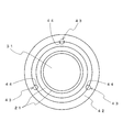
- FIG. 2 is a front view of the lens unit held by the unit holding unit
- FIG. 3 is a schematic sectional view of the unit holding unit.
- FIG. 3 shows a cross section of the lens unit in the optical axis direction (cross section at the position indicated by the line A-A ′ in FIG. 1).
- a convex surface which is a part of a spherical surface having a predetermined position on the optical axis of the imaging lens as the center position CP, serves as a rolling surface 22 in a band shape in the circumferential direction of the surface of the lens barrel 21. Is formed.
- a ball holding portion 43 is formed on a surface facing the rolling surface 22 formed on the lens barrel 21, and the ball 44 can roll on the rolling surface 22 by the ball holding portion 43. Is held in.
- a plurality of ball holding portions 43 are formed so as to sandwich the top of the rolling surface 22. For example, in FIG. 3, two are formed so as to sandwich the top of the rolling surface 22.
- a plurality of ball holding portions 43 are provided in the circumferential direction of the lens barrel 21 with respect to the unit holding portion 42 so that the position of the lens barrel 21 does not move in the radial direction.
- the interval between the ball holding portions 43 is provided to be 120 degrees.
- the lens unit 20 can be rotated in the yawing direction and the pitching direction with the center position CP of the rolling surface 22 as a reference while being held by the unit holding portion 42.
- the unit holding part 42 is formed in, for example, a casing 41 described later.
- FIG. 4 is a perspective view showing a configuration of a drive unit that rotationally drives the lens unit in the yawing direction and the pitching direction.
- the drive unit 45 is provided on the housing surface facing the rear end surface of the lens unit 20.
- the drive unit 45 includes drive coils 45ya and 45yb that rotate the lens unit 20 in the yawing direction, and drive coils 45pa and 45pb that rotate the lens unit 20 in the pitching direction.
- a magnet 25ya is provided on the rear end surface of the lens unit 20 at a position corresponding to the drive coil 45ya.
- magnets 25yb, 25pa, and 25pb are provided at positions corresponding to the drive coils 45yb, 45pa, and 45pb.
- the magnet 25ya has a configuration in which a magnet whose magnetic pole on the surface facing the drive coil 45ya is an S pole and a magnet whose N pole is an N pole are arranged in a horizontal direction.
- a magnet whose magnetic pole on the surface facing the drive coil is an S pole is indicated by hatching.
- the magnet 25yb has a configuration in which a magnet whose magnetic pole on the surface facing the drive coil 45yb is an S pole and a magnet whose N pole is an N pole are arranged in a horizontal direction.
- the magnet 25pa has a configuration in which a magnet whose magnetic pole on the surface facing the drive coil 45pa is an S pole and a magnet whose N pole is an N pole are arranged in the vertical direction.
- the magnet 25pb has a configuration in which a magnet whose magnetic pole on the surface facing the drive coil 45pb is an S pole and a magnet whose N pole is an N pole are arranged in the vertical direction.
- the magnet 25ya (25yb) and the drive coil 45ya (45yb) are arranged between two magnets arranged horizontally in the magnet 25ya (25yb) in a state where the lens unit 20 is at the center position (center position of the rotation range).
- the central position is arranged to be the central position of the drive coil 45ya (45yb).
- the magnet 25pa (25pb) and the drive coil 45pa (45pb) are driven at the center position between two magnets arranged in the vertical direction in the magnet 25pa (25pb) in a state where the lens unit 20 is at the center position. It arrange
- a detection unit 46 is provided.
- the position detection unit 46 is configured using, for example, Hall elements 46ya (46yb) and 46pa (46pb).
- FIG. 5 is a diagram for explaining the operation of the drive unit.
- FIG. 5 illustrates the rotation operation in the pitching direction.
- the drive unit 45 is provided on the housing surface 411 facing the rear end surface of the lens unit 20.
- the center position CP of the rolling surface 22 is used as a rotation fulcrum. It is held rotatably.
- the center position between the two magnets arranged in the vertical direction in the magnet 25pa (25pb) is the center of the drive coil 45pa (45pb). It arrange
- a current is supplied to the drive coil 45pa (45pb)
- a magnetic field is generated according to the supplied current, and the magnet 25pa (25pb) is moved in the vertical direction by the generated magnetic field. That is, the image blur in the pitching direction can be corrected by supplying current to the drive coil 45pa (45pb) and rotating the lens unit 20 according to the shake in the pitching direction applied to the lens unit 20.
- the image blur in the yawing direction is corrected by supplying current to the drive coil 45ya (45yb) and rotating the lens unit 20 in accordance with the yaw direction shake applied to the lens unit 20. Can do.
- the image blur can be corrected by rotating the lens unit 20 by the driving unit 45 in accordance with the shake applied to the lens unit 20.
- the configuration for rotating the lens unit 20 in the yawing direction and the pitching direction is not limited to the configuration shown in FIGS.
- a first rotation shaft is provided in the vertical direction (horizontal direction) with respect to the lens unit, and the first rotation shaft is rotatably held by the inner frame. Further, the first rotating shaft is rotated in the yawing direction (pitching direction) by a motor or the like.
- a second rotating shaft is provided in the horizontal direction (vertical direction) with respect to the inner frame, and the second rotating shaft is rotatably held by the outer frame. Further, the second rotating shaft is rotated in the pitching direction (yawing direction) by a motor or the like.
- the lens unit 20 may be rotatably supported by the first rotation shaft and the second rotation shaft, and the first rotation shaft and the second rotation shaft may be rotated by a motor or the like.
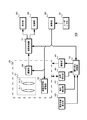
- FIG. 6 illustrates the configuration of the first embodiment.
- the imaging apparatus 10 using the image shake correction apparatus includes a lens unit 20, a drive unit 45, a position detection unit 46, an image processing unit 51, a display unit 52, a recording unit 53, a shake detection unit 61, a gravity center position calculation unit 62, a shake.
- a correction control unit 70, a user interface unit 81, and a control unit 85 are provided.
- the lens unit 20 is provided with an imaging optical system 31, an imaging optical system driving unit 32, and an imaging unit 33.
- the imaging optical system 31 includes a focus lens 311 and a zoom lens 312.
- the focus lens 311 is moved in the optical axis direction to perform focus adjustment. Further, the focal length is varied by moving the zoom lens 312 in the optical axis direction.
- the imaging optical system drive unit 32 drives the focus lens 311 and the zoom lens 312 based on a control signal from the control unit 85 described later.
- the imaging unit 33 includes an imaging element, a preprocessing unit, an imaging drive unit, and the like.
- the imaging element performs photoelectric conversion processing, and converts an optical image formed on the imaging surface by the imaging optical system 31 into an electrical signal.
- a CCD (Charge-Coupled Device) image sensor or a CMOS (Complementary Metal-Oxide Semiconductor) image sensor is used as the imaging device.
- the preprocessing unit performs noise removal processing such as CDS (correlated double sampling) on the electrical signal generated by the image sensor.
- the preprocessing unit performs gain adjustment to set the signal level of the electrical signal to a desired signal level.
- the preprocessing unit performs A / D conversion processing, converts an analog image signal, which is an electrical signal subjected to noise removal processing and gain adjustment, into a digital image signal, and outputs the digital image signal to the image processing unit 51.
- the imaging drive unit generates an operation pulse or the like necessary for driving the imaging device based on a control signal from the control unit 85 described later. For example, a charge readout pulse for reading out charges, a transfer pulse for transferring in the vertical and horizontal directions, a shutter pulse for performing an electronic shutter operation, and the like are generated.
- the drive unit 45 rotates the lens unit 20 in the yawing direction and the pitching direction as described above based on the drive signal supplied from the shake correction control unit 70.
- the position detection unit 46 generates a detection signal corresponding to the position of the lens unit 20 and outputs the detection signal to the shake correction control unit 70.
- detection signals generated by the Hall elements 46ya (46yb) and 46pa (46pb) are output to the shake correction control unit 70.
- the image processing unit 51 performs camera process processing on the digital image signal output from the imaging unit 33.
- the image processing unit 51 performs, for example, nonlinear processing such as gamma correction and knee correction, color correction processing, contour enhancement processing, and the like on the image signal.
- the image processing unit 51 outputs the processed image signal to the display unit 52 and the recording unit 53.
- the display unit 52 constitutes a display panel and an electronic viewfinder, and displays a camera-through image based on the image signal output from the image processing unit 51.
- the display unit 52 also performs menu display, operation state display, and the like for setting the operation of the imaging apparatus 10.
- the display part 52 performs the process which converts a captured image into the display image of a display image number, when the number of display pixels is smaller than a captured image.
- the recording unit 53 records the image signal output from the image processing unit 51 on a recording medium.
- the recording medium may be detachable like a memory card, optical disk, magnetic tape, etc., or may be a fixed type HDD (Hard Disk Drive), a semiconductor memory module, or the like.
- an encoder or a decoder may be provided in the recording unit 53 to perform compression encoding or decompression decoding of the image signal, and the encoded signal may be recorded on the recording medium.
- the recording unit 53 may read the image signal or the encoded signal recorded on the recording medium and display the recorded image on the display unit 52.
- the shake detection unit 61 is configured using a sensor that detects a shake applied to the imaging apparatus 10 (lens unit 20), such as an acceleration sensor or a gyro sensor.
- the shake detection unit 61 detects a shake applied to the imaging device 10 (lens unit 20), and outputs a detection result to the shake correction control unit 70.
- the center-of-gravity position calculation unit 62 calculates the center-of-gravity position of the lens unit 20 that changes according to the position of the focus lens 311 and zoom lens 312 of the imaging optical system 31 and the extended state of the lens barrel 21.
- the gravity center position is calculated in advance for each position of the focus lens 311 and the zoom lens 312 and the extended state of the lens barrel 21 and stored in the gravity center position calculation unit 62 as a table.
- the center-of-gravity position calculation unit 62 acquires information indicating the position of the focus lens 311 and the zoom lens 312 and the extension state of the lens barrel 21 from the lens unit 20, and selects the center-of-gravity position corresponding to the acquired information from the table.
- the gravity center position of the lens unit 20 is calculated.
- the center-of-gravity position calculation unit 62 calculates the center-of-gravity position of the lens unit 20 by performing calculation each time based on the positions of the focus lens 311 and the zoom lens 312 of the imaging optical system 31 and the extended state of the lens barrel 21. Also good. Further, the center-of-gravity position calculation unit 62 may calculate the center-of-gravity position of the lens unit 20 using a control signal supplied from the control unit 85 to the imaging optical system driving unit 32. For example, the center-of-gravity position calculation unit 62 determines the positions of the focus lens 311 and the zoom lens 312 and the extension state of the lens barrel 21 based on the control signal supplied to the imaging optical system driving unit 32, and the lens unit based on the determination result. The center of gravity position of 20 is calculated. The centroid position calculation unit 62 outputs the centroid position of the lens unit 20 to the shake correction control unit 70.
- the shake correction control unit 70 generates a drive signal based on the shake detected by the shake detection unit 61 and the position of the lens unit 20 detected by the position detection unit 46.
- the shake correction control unit 70 supplies the generated drive signal to the drive unit 45 so that the image pickup unit 33 can generate an image signal of a captured image in which image shake is corrected.
- the shake correction control unit 70 controls the generation of the drive signal based on the centroid position calculated by the centroid position calculation unit 62, and the image shake is corrected even if the centroid position of the lens unit 20 fluctuates.
- the image signal of the captured image can be stably generated by the imaging unit 33.
- the user interface (user I / F) unit 81 includes a zoom lever, a shooting button, and the like.
- the user I / F unit 81 generates an operation signal corresponding to the user operation and outputs it to the control unit 85.
- the control unit 85 includes, for example, a CPU (Central Processing Unit), a ROM (Read Only Memory), and a RAM (Random Access Memory).
- the CPU reads and executes the program stored in the ROM as necessary.
- the ROM stores in advance programs executed by the CPU, data necessary for various processes, and the like.
- the RAM is a memory used as a so-called work area that temporarily stores intermediate results of processing.
- the ROM or RAM stores various control information and correction data.
- the control unit 85 controls each unit in accordance with an operation signal from the user I / F unit 81 and causes the imaging device 10 to perform an operation corresponding to the user operation.
- the control unit 85 controls the shake correction control unit 70 to perform an image shake correction operation.
- FIG. 7 illustrates the configuration of the shake correction control unit.
- the shake correction control unit 70 includes a shake amount calculation unit 71, a target position calculation unit 72, a current position calculation unit 73, a calculation unit 74, a parameter setting unit 75, a servo calculation unit 76, and a drive signal output unit 77.
- the shake amount calculation unit 71 calculates the shake amount of shake applied to the imaging device 10 (lens unit 20) based on the detection signal supplied from the shake detection unit 61.
- the shake amount calculation unit 71 outputs the calculated shake amount to the target position calculation unit 72.
- the target position calculation unit 72 calculates the position of the lens unit 20 that can generate an image signal of a captured image in which no image shake has occurred in the image pickup unit 33, and calculates the position.
- the obtained position is output to the calculation unit 74 as a target position.
- the current position calculation unit 73 calculates the current position of the lens unit 20 based on detection signals from the position detection unit 46, for example, detection signals generated by the hall elements 46ya (46yb) and 46pa (46pb). The current position calculation unit 73 outputs the calculated current position to the calculation unit 74.
- the calculation unit 74 calculates an error between the target position and the current position, and outputs a position error signal indicating the calculated error amount to the servo calculation unit 76.
- the parameter setting unit 75 sets parameters used in the servo calculation unit 76 based on a control signal from the control unit 85. Further, the parameter setting unit 75 outputs the image signal of the captured image in which the image blur is corrected even if the center of gravity position of the lens unit 20 fluctuates based on the center of gravity position calculated by the center of gravity position calculating unit 62. Change the parameters so that can be generated stably with.
- the servo calculation unit 76 performs a servo operation using the parameters set by the parameter setting unit 75, generates a control signal so that the error amount calculated by the calculation unit 74 becomes “0”, and generates a drive signal output unit. Output to 77.
- the drive signal output unit 77 generates a drive signal based on the control signal supplied from the servo calculation unit 76 and supplies the drive signal to the drive unit 45 so that the lens unit 20 calculates the target position calculated by the target position calculation unit 72.
- the lens unit 20 is driven by the driving unit 45 so as to be.
- the shake correction control unit 70 performs feedback control based on the detection result of the shake detection unit 61 and the center of gravity position and the current position of the lens unit, and outputs the image signal of the captured image whose image shake has been corrected by the imaging unit 33. To be generated.
- the servo calculation unit 76 performs feedback control by PID control that selectively combines, for example, proportional control (P control), integral control (I control unit), and differential control (D control).
- PID control differential control
- I control integral control
- PID control differential control
- I control integral control
- PID control is performed by selecting and combining these proportional control, differential control, and integral control as necessary.
- the calculation of equation (1) is performed to calculate the control output.
- Deviation x Proportional gain Proportional control output (1)
- the control output is calculated by performing the calculation of Expression (2).
- x Differential gain Differential control output (2)
- the calculation of equation (3) is performed to calculate the control output.
- x integral gain integral control output (3)
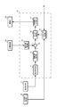
- FIG. 8 illustrates the configuration of the servo calculation unit.
- the servo calculation unit 76 includes amplification units 761, 764, 767, delay units 762, 766, and calculation units 763, 765, 769.
- the amplification unit 761 multiplies the position error signal supplied from the calculation unit 74 by the proportional gain Kp set by the parameter setting unit 75 to generate a proportional control signal that is a proportional control output.
- the amplification unit 761 outputs the generated proportional control signal to the calculation unit 769.
- the delay unit 762 delays the position error signal supplied from the calculation unit 74 by one sampling period and outputs it to the calculation unit 763.
- the calculation unit 763 performs calculation processing for subtracting the position error signal output from the delay unit 762 from the position error signal supplied from the calculation unit 74, generates a differential signal of the position error, and supplies it to the amplification unit 764. Output.
- the amplification unit 764 multiplies the differential signal supplied from the calculation unit 763 by the differential gain Kd set by the parameter setting unit 75 to generate a differential control signal that is a differential control output.
- the amplification unit 764 outputs the generated differential control signal to the calculation unit 769.
- the arithmetic unit 765 performs arithmetic processing for adding the signal output from the delay unit 766 to the position error signal supplied from the arithmetic unit 74, generates an integral signal of the position error, and outputs the integrated signal to the amplifying unit 767. .
- the delay unit 766 delays the integration signal supplied from the calculation unit 765 by one sampling period and outputs the integration signal to the calculation unit 765.
- the amplification unit 767 multiplies the integration signal supplied from the calculation unit 765 by the integration gain Ki set by the parameter setting unit 75 to generate an integration control signal that is an integration control output.
- the amplification unit 767 outputs the generated integration control signal to the calculation unit 768.
- the calculation unit 768 adds the gravity compensation signal supplied from the parameter setting unit 75 to the integration control signal supplied from the amplification unit 767 and outputs the added signal to the calculation unit 769.
- the gravity compensation signal is a signal for canceling the load due to gravity, and will be described in detail later.
- the calculation unit 769 adds the proportional control signal supplied from the amplification unit 761, the differential control signal supplied from the amplification unit 764, and the integration control signal supplied from the calculation unit 768 (after adding the gravity compensation signal). Then, the control signal after the addition is output to the drive signal output unit 77.
- a signal corresponding to the load due to gravity is added to the integral signal supplied to the amplification unit 767, and then the amplification unit 767 multiplies the integral gain Ki to add the gravity compensation signal.
- a control signal equivalent to the integration control signal may be generated.
- a gain (gravity compensation gain) corresponding to a load due to gravity may be added to the integral gain Ki to generate a control signal equivalent to the integral control signal to which the gravity compensation signal is added.
- the control method is not limited to PID control, and other control methods may be used.
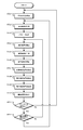
- FIG. 9 is a flowchart showing the operation of the first embodiment.
- the shake correction control unit 70 determines the position of the center of gravity.
- the shake correction control unit 70 acquires the gravity center position of the lens unit 20 calculated by the gravity center position calculation unit 62, determines the gravity center position, and proceeds to step ST2.
- step ST2 the shake correction control unit 70 performs parameter setting.
- the shake correction control unit 70 sets parameters based on a control signal from the control unit 85. Further, the shake correction control unit 70 changes the parameter according to the position of the center of gravity of the lens unit 20, and proceeds to step ST3.
- step ST3 the shake correction control unit 70 calculates a target position.
- the shake correction control unit 70 calculates the shake amount of shake applied to the imaging device 10 (lens unit 20) based on the detection signal supplied from the shake detection unit 61. Based on the calculated shake amount, the shake correction control unit 70 calculates the position of the lens unit 20 that can generate an image signal of a captured image in which no image shake has occurred in the imaging unit 33, and proceeds to step ST4 as a target position.
- step ST4 the shake correction control unit 70 determines the current position.
- the shake correction control unit 70 acquires the detection signal from the position detection unit 46, calculates the current position of the lens unit 20 based on the acquired detection signal, determines the current position, and proceeds to step ST5.
- step ST5 the shake correction control unit 70 calculates a position error.
- the shake correction control unit 70 calculates an error between the target position and the current position, generates a position error signal indicating the calculated error, and proceeds to step ST6.
- step ST6 the shake correction control unit 70 generates a proportional control signal.
- the shake correction control unit 70 performs the calculation shown in the above equation (1), multiplies the position error signal by the proportional gain Kp, generates a proportional control signal, and proceeds to step ST7.
- step ST7 the shake correction control unit 70 generates a differentiation control signal.
- the shake correction control unit 70 performs the calculation shown in the above equation (2), generates a differential signal from the position error signal, multiplies the differential gain Kd, generates a differential control signal, and proceeds to step ST8.
- step ST8 the shake correction control unit 70 generates an integration control signal.
- the shake correction control unit 70 performs the calculation shown in the above equation (3), generates an integral signal from the position error signal, and multiplies the integral gain Ki to generate an integral control signal.
- the shake correction control unit 70 adds the gravity compensation signal to the integral control signal, and proceeds to step ST9.
- step ST9 the shake correction control unit 70 outputs a drive signal.
- the shake correction control unit 70 adds the proportional control signal, the differential control signal, and the integral control signal, and generates a drive signal based on the control signal after the addition.
- the shake correction control unit 70 outputs the generated drive signal to the drive unit 45, and proceeds to step ST10.
- step ST10 the shake correction control unit 70 determines whether there is a change in the gravity center position.
- the shake correction control unit 70 determines whether or not a change in the position of the center of gravity occurs due to the movement operation of the focus lens and zoom lens and the expansion and contraction operation of the lens barrel.
- the shake correction control unit 70 returns to step ST1 when it is determined that there is a change in the center of gravity position, and returns to step ST3 when it is not determined that there is a change in the center of gravity position.
- steps ST6 to ST8 are not limited to the order shown in the figure.
- the parameter setting unit 75 of the shake correction control unit 70 obtains, from the control unit 85, a proportional gain Kp, a differential gain Kd, and an integral gain Ki that can perform stable image shake correction when the center of gravity is at a predetermined position, for example. Set based on the control signal.
- the parameter setting unit 75 supplies the set parameters to the servo calculation unit 76.
- the gravity center position calculated by the gravity center position calculation unit 62 is different from a predetermined position, for example, when the position is away from the support position where the lens unit 20 is rotatably supported, the lens unit 20 is rotated. Requires a larger driving force.
- the parameter setting unit 75 increases the driving force of the lens unit 20 by increasing the proportional gain Kp according to the increase in inertia based on the position of the center of gravity. Further, the parameter setting unit 75 adjusts the differential gain Kd and the integral gain Ki so that satisfactory image blur correction can be performed even if the proportional gain Kp is increased. For example, even when the proportional gain Kp is increased, good response can be obtained, and the differential gain Kd is adjusted so that feedback control can be performed stably without causing oscillation. Even when the proportional gain Kp is increased, the integral gain Ki is adjusted so that the offset characteristic of the feedback control is good so that the lens unit 20 is surely at the target position.
- integration control is performed using a correction value corresponding to the position of the center of gravity of the lens unit. For example, as described above, an integration control signal to which a gravity compensation signal for canceling a load that changes depending on the position of the center of gravity of the lens unit (a load in the rotation direction due to gravity) is added is generated. Alternatively, a signal corresponding to the load due to gravity is added to the integral signal and then multiplied by the integral gain Ki to generate a control signal equivalent to the integral control signal to which the gravity compensation signal is added.
- a gravity compensation gain corresponding to the load due to gravity is added to the integral gain Ki to generate a control signal equivalent to the integral control signal to which the gravity compensation signal is added. If the integration control signal is generated in this way, it is possible to prevent the lens unit 20 from being tilted by the influence of gravity before the lens unit 20 approaches the target position.
- servo operation is performed including weighting due to gravity. Therefore, the addition of the gravity compensation signal or the gravity compensation gain may be performed for a predetermined period from the start of control to the stabilization of the integral value.
- the shake correction control unit 70 uses the focus lens,
- the servo operation parameters are changed according to the movement of the center of gravity of the lens unit 20 caused by the zoom lens movement operation, the lens barrel expansion / contraction operation, and the like. Therefore, for example, even when the focus adjustment operation or the zoom operation is performed in the imaging apparatus and the gravity center position of the lens unit fluctuates, it is possible to perform optimal image blur correction, and to improve image blur correction performance.
- the servo operation parameters are changed according to the movement of the center of gravity, the driving force when rotating the lens unit 20 is not excessive, and the power consumption is prevented from increasing. Thus, image blur correction can be performed efficiently.
- the fluctuation of the center of gravity position of the lens unit is not limited to the focus adjustment operation and the zoom operation.
- the center of gravity of the lens unit moves forward.
- the weight of the lens unit increases due to the attachment of the accessory. Therefore, in the second embodiment, a case will be described in which the control operation in image blur correction is switched according to the accessory mounting state.
- FIG. 10 illustrates the configuration of the second embodiment.
- the imaging device 11 using the image blur correction device includes a lens unit 20, a drive unit 45, a position detection unit 46, an image processing unit 51, a display unit 52, a recording unit 53, a shake detection unit 61, a gravity center position calculation unit 62, and accessories.
- a detection unit 63, a shake correction control unit 70, a user interface (user I / F) unit 81, and a control unit 85 are included.
- the lens unit 20 is provided with an imaging optical system 31, an imaging optical system driving unit 32, and an imaging unit 33.
- the imaging optical system 31 includes a focus lens 311 and a zoom lens 312.
- the focus lens 311 is moved in the optical axis direction to perform focus adjustment. Further, the focal length is varied by moving the zoom lens 312 in the optical axis direction.
- the imaging optical system drive unit 32 drives the focus lens 311 and the zoom lens 312 based on a control signal from the control unit 85 described later.
- the imaging unit 33 includes an imaging element, a preprocessing unit, an imaging drive unit, and the like.
- the imaging element performs photoelectric conversion processing, and converts an optical image formed on the imaging surface by the imaging optical system 31 into an electrical signal.
- a CCD (Charge-Coupled Device) image sensor or a CMOS (Complementary Metal-Oxide Semiconductor) image sensor is used as the imaging device.
- the preprocessing unit performs noise removal processing such as CDS (correlated double sampling) on the electrical signal generated by the image sensor.
- the preprocessing unit performs gain adjustment to set the signal level of the electrical signal to a desired signal level.
- the preprocessing unit performs A / D conversion processing, converts an analog image signal, which is an electrical signal subjected to noise removal processing and gain adjustment, into a digital image signal, and outputs the digital image signal to the image processing unit 51.
- the imaging drive unit generates an operation pulse or the like necessary for driving the imaging device based on a control signal from the control unit 85 described later. For example, a charge readout pulse for reading out charges, a transfer pulse for transferring in the vertical and horizontal directions, a shutter pulse for performing an electronic shutter operation, and the like are generated.
- the drive unit 45 rotates the lens unit 20 in the yawing direction and the pitching direction as described above based on the drive signal supplied from the shake correction control unit 70.
- the position detection unit 46 generates a detection signal corresponding to the position of the lens unit 20 and outputs the detection signal to the shake correction control unit 70.
- detection signals generated by the Hall elements 46ya (46yb) and 46pa (46pb) are output to the shake correction control unit 70.
- the image processing unit 51 performs camera process processing on the digital image signal output from the imaging unit 33.
- the image processing unit 51 performs, for example, nonlinear processing such as gamma correction and knee correction, color correction processing, contour enhancement processing, and the like on the image signal.
- the image processing unit 51 outputs the processed image signal to the display unit 52 and the recording unit 53.
- the display unit 52 constitutes a display panel and an electronic viewfinder, and displays a camera-through image based on the image signal output from the image processing unit 51.
- the display unit 52 also performs menu display, operation state display, and the like for setting the operation of the imaging device 11.
- the display part 52 performs the process which converts a captured image into the display image of a display image number, when the number of display pixels is smaller than a captured image.
- the recording unit 53 records the image signal output from the image processing unit 51 on a recording medium.
- the recording medium may be detachable like a memory card, optical disk, magnetic tape, etc., or may be a fixed type HDD (Hard Disk Drive), a semiconductor memory module, or the like.
- an encoder or a decoder may be provided in the recording unit 53 to perform compression encoding or decompression decoding of the image signal, and the encoded signal may be recorded on the recording medium.
- the recording unit 53 may read the image signal or the encoded signal recorded on the recording medium and display the recorded image on the display unit 52.
- the shake detection unit 61 is configured using a sensor that detects a shake applied to the imaging device 11 (lens unit 20), such as an acceleration sensor or a gyro sensor.
- the shake detection unit 61 detects a shake applied to the imaging device 11 (lens unit 20), and outputs a detection result to the shake correction control unit 70.
- the center-of-gravity position calculation unit 62 calculates the center of gravity of the lens unit 20 that changes according to the position of the focus lens 311 and the zoom lens 312 of the imaging optical system 31 and the extension state of the lens barrel 21. For example, the gravity center position is calculated in advance for each position of the focus lens 311 and zoom lens 312 and the lens barrel 21 is extended, and is stored in the gravity center position calculation unit 62.
- the center-of-gravity position calculation unit 62 acquires information indicating the positions of the focus lens 311 and the zoom lens 312 and the extension state of the lens barrel 21 from the lens unit 20, and selects the center-of-gravity position corresponding to the acquired information.
- the center of gravity of the unit 20 is calculated.
- the center-of-gravity position calculation unit 62 may calculate the center of gravity of the lens unit 20 using a control signal supplied from the control unit 85 to the imaging optical system driving unit 32. For example, the center-of-gravity position calculation unit 62 determines the positions of the focus lens 311 and the zoom lens 312 and the extension state of the lens barrel 21 based on the control signal supplied to the imaging optical system driving unit 32, and the lens unit based on the determination result. The center of gravity position of 20 is calculated. The centroid position calculation unit 62 outputs the centroid position of the lens unit 20 to the shake correction control unit 70.
- the accessory detection unit 63 detects whether or not an accessory is attached to the lens unit 20. Further, when a plurality of types of accessories can be attached, it is detected what kind of accessories are attached. For example, the accessory detection unit 63 automatically detects whether an accessory such as a conversion lens is attached to the tip of the lens unit 20. The detection of attachment may detect that the accessory is attached using an optical detection means such as a switch or a photo reflector, and communicates with the accessory to acquire information about the accessory when detecting attachment of the accessory. You may do it.
- Accessories refer to conversion lenses such as teleconverters and wide converters, filters, hoods, and the like that are attached to the lens unit.
- the accessory detection unit 63 outputs the detection result to the shake correction control unit 70.
- the shake correction control unit 70 generates a drive signal based on the shake detected by the shake detection unit 61 and the position of the lens unit 20 detected by the position detection unit 46.
- the shake correction control unit 70 supplies the generated drive signal to the drive unit 45 so that the image pickup unit 33 can generate an image signal of a captured image in which image shake is corrected.
- the shake correction control unit 70 controls the generation of the drive signal based on the centroid position calculated by the centroid position calculation unit 62, and the image shake is corrected even if the centroid position of the lens unit 20 fluctuates.
- the image signal of the captured image can be stably generated by the imaging unit 33.
- the shake correction control unit 70 controls the generation of the drive signal based on the detection result of the accessory detection unit 63, and the image shake is corrected even if the center of gravity of the lens unit 20 fluctuates or the weight increases.
- the imaging unit 33 can stably generate an image signal of a captured image.
- the user I / F unit 81 includes a zoom lever, a shooting button, and the like.
- the user I / F unit 81 generates an operation signal corresponding to the user operation and outputs it to the control unit 85.
- the control unit 85 includes, for example, a CPU (Central Processing Unit), a ROM (Read Only Memory), and a RAM (Random Access Memory).
- the CPU reads and executes the program stored in the ROM as necessary.
- the ROM stores in advance programs executed by the CPU, data necessary for various processes, and the like.
- the RAM is a memory used as a so-called work area that temporarily stores intermediate results of processing.
- the ROM or RAM stores various control information and correction data.
- the control unit 85 controls each unit according to an operation signal from the user I / F unit 81 and causes the imaging device 11 to perform an operation according to the user operation.
- the control unit 85 controls the shake correction control unit 70 to perform an image shake correction operation.
- FIG. 11 is a flowchart showing the operation of the second embodiment.
- the shake correction control unit 70 detects accessories.
- the shake correction control unit 70 detects what accessories are attached to the lens unit 20 based on the detection result of the accessory detection unit 63, and proceeds to step ST22.
- step ST22 the shake correction control unit 70 determines the position of the center of gravity.
- the shake correction control unit 70 acquires the gravity center position of the lens unit 20 calculated by the gravity center position calculation unit 62, determines the gravity center position, and proceeds to step ST23.
- step ST23 the shake correction control unit 70 performs parameter setting.
- the shake correction control unit 70 sets parameters based on a control signal from the control unit 85. Further, the shake correction control unit 70 changes the parameter according to the position of the center of gravity of the lens unit 20, and proceeds to step ST24.
- step ST24 the shake correction control unit 70 calculates a target position.
- the shake correction control unit 70 calculates a shake amount of shake applied to the imaging device 11 (lens unit 20) based on the detection signal supplied from the shake detection unit 61. Based on the calculated shake amount, the shake correction control unit 70 calculates the position of the lens unit 20 that can generate an image signal of a captured image in which no image shake has occurred in the imaging unit 33, and proceeds to step ST25 as a target position.
- step ST25 the shake correction control unit 70 determines the current position.
- the shake correction control unit 70 acquires the detection signal from the position detection unit 46, calculates the current position of the lens unit 20 based on the acquired detection signal, determines the current position, and proceeds to step ST26.
- step ST26 the shake correction control unit 70 calculates a position error.
- the shake correction control unit 70 calculates an error between the target position and the current position, generates a position error signal indicating the calculated error, and proceeds to step ST27.
- step ST27 the shake correction control unit 70 generates a proportional control signal.
- the shake correction control unit 70 performs the calculation shown in the above equation (1), multiplies the position error signal by the proportional gain Kp, generates a proportional control signal, and proceeds to step ST28.
- step ST28 the shake correction control unit 70 generates a differentiation control signal.
- the shake correction control unit 70 performs the calculation shown in the above equation (2), generates a differential signal from the position error signal, multiplies the differential gain Kd, generates a differential control signal, and proceeds to step ST29.
- step ST29 the shake correction control unit 70 generates an integration control signal.
- the shake correction control unit 70 performs the calculation shown in the above equation (3), generates an integral signal from the position error signal, and multiplies the integral gain Ki to generate an integral control signal. Further, the shake correction control unit 70 adds the gravity compensation signal to the integral control signal, and proceeds to step ST30.
- step ST30 the shake correction control unit 70 outputs a drive signal.
- the shake correction control unit 70 adds the proportional control signal, the differential control signal, and the integral control signal, and generates a drive signal based on the control signal after the addition.
- the shake correction control unit 70 outputs the generated drive signal to the drive unit 45, and proceeds to step ST31.
- step ST31 the shake correction control unit 70 determines whether the accessory has changed. Based on the detection result of the accessory detection unit 63, the shake correction control unit 70 determines whether the accessory has been changed, that is, whether the accessory has been attached or detached or has been changed to a different accessory. The shake correction control unit 70 proceeds to step ST32 when the accessory is not changed, and returns to step ST21 when the accessory is changed.
- step ST32 the shake correction control unit 70 determines whether there is a change in the position of the center of gravity.
- the shake correction control unit 70 determines whether or not a change in the position of the center of gravity occurs due to the movement operation of the focus lens and zoom lens and the expansion and contraction operation of the barrel.
- the shake correction control unit 70 returns to step ST22 when determining that there is a change in the center of gravity position, and returns to step ST24 when it is not determined that there is a change in the center of gravity position.
- step ST24 and step ST25 may perform any process of step ST24 and step ST25 first. Further, the processing of step ST27 to step ST29 is not limited to the order shown in the figure.
- the shake correction control unit 70 uses the focus lens and The servo operation parameters are changed according to the movement of the center of gravity of the lens unit 20 caused by the zoom lens movement operation, the lens barrel expansion / contraction operation, and the like. Further, the servo operation parameters are changed according to the attachment / detachment state of the accessory and the attached accessory. Therefore, for example, even if a focus adjustment operation or a zoom operation is performed in the imaging apparatus and the position of the center of gravity of the lens unit fluctuates or an accessory is used, optimal image blur correction can be performed. Correction performance can be improved.
- the driving force when rotating the lens unit 20 is not excessive, and the power consumption is prevented from increasing. it can. Further, even when the accessory is attached and the weight of the lens unit is increased, the driving force for rotating the lens unit 20 is not insufficient, and image blur correction can be performed efficiently.
- the series of processes described in the specification can be executed by hardware, software, or a combined configuration of both.
- a program in which a processing sequence is recorded is installed and executed in a memory in a computer incorporated in dedicated hardware.
- the program can be installed and executed on a general-purpose computer capable of executing various processes.
- the program can be recorded in advance on a hard disk or ROM (Read Only Memory) as a recording medium.
- the program can be temporarily or permanently stored on a removable recording medium such as a flexible disk, CD-ROM (Compact Disc Read Only Memory), MO (Magneto optical disc), DVD (Digital Versatile Disc), magnetic disk, semiconductor memory card, etc. Can be stored (recorded).
- a removable recording medium can be provided as so-called package software.
- the program may be transferred from the download site to the computer wirelessly or by wire via a network such as a LAN (Local Area Network) or the Internet.
- the computer can receive the program transferred in this way and install it on a recording medium such as a built-in hard disk.
- the present technology should not be construed as being limited to the embodiments of the technology described above.
- the embodiments of this technology disclose the present technology in the form of examples, and it is obvious that those skilled in the art can make modifications and substitutions of the embodiments without departing from the gist of the present technology. In other words, the scope of the claims should be considered in order to determine the gist of the present technology.
- the image blur correction apparatus of the present technology can also have the following configuration.
- a lens unit that has an imaging optical system and an imaging unit that generates an image signal of a captured image, and is supported rotatably in the yawing direction and the pitching direction;
- a shake detector for detecting shake applied to the lens unit;
- a position detector for detecting the position of the lens unit;
- a drive unit that rotationally drives the lens unit in the yawing direction and the pitching direction; Based on the shake detected by the shake detection unit, the position detected by the position detection unit, and the center of gravity of the lens unit, the drive operation of the drive unit is controlled to correct the image shake of the captured image.
- a shake correction control unit Based on the shake detected by the shake detection unit, the position detected by the position detection unit, and the center of gravity of the lens unit, the drive operation of the drive unit is controlled to correct the image shake of the captured image.
- a shake correction control unit Based on the shake detected by the shake detection unit, the position detected by the position detection unit, and
- the shake correction control unit includes a deviation between a target position of the lens unit calculated based on the shake detected by the shake detection unit and a position of the lens unit detected by the position detection unit, and Image blur correction according to (1), wherein proportional control, differential control, and integral control are performed in combination according to the position of the center of gravity of the lens unit, and the driving operation is controlled so that the position of the lens unit matches the target position. apparatus.
- the correction value is set so as to cancel a load that varies depending on a position of the center of gravity of the lens unit.
- a centroid position calculation unit that calculates the centroid position of the lens unit; The image center correction apparatus according to any one of (1) to (4), wherein the center-of-gravity position calculation unit calculates the center-of-gravity position based on a lens position of the lens unit and a lens barrel extension state of the lens unit.
- An accessory detection unit that detects attachment of the accessory to the lens unit, The image blur correction apparatus according to any one of (1) to (5), wherein the shake correction control unit controls a drive operation of the drive unit using a detection result of the accessory detection unit.
- a lens unit including an image pickup optical system and an image pickup unit that generates an image signal of a picked-up image is supported so as to be rotatable in the yawing direction and the pitching direction.
- the drive operation of the drive unit that rotationally drives the lens unit in the yawing direction and the pitching direction is controlled to correct the image shake of the captured image.
- Accessory detection unit 70 Calculation unit 72... Target position calculation unit 73. Current position calculation unit, 74, 763, 765, 768, 769 ... calculation unit, 75 ... parameter setting unit, 76 ... servo calculation unit, 77 ... drive signal output unit, 81 ... user Interface (user I / F) unit, 85 ... control unit, 311 ... focus lens, 312 ... zoom lens, 411 ... housing surface, 761, 764, 767 ... amplification unit, 762 766 ... Delay unit
Landscapes
- Engineering & Computer Science (AREA)
- Multimedia (AREA)
- Signal Processing (AREA)
- Physics & Mathematics (AREA)
- General Physics & Mathematics (AREA)
- Optics & Photonics (AREA)
- Adjustment Of Camera Lenses (AREA)
- Studio Devices (AREA)
Abstract
Description
撮像光学系と撮像画像の画像信号を生成する撮像部を有してヨーイング方向およびピッチング方向に回転可能に支持されているレンズユニットと、
前記レンズユニットに加わる振れを検出する振れ検出部と、
前記レンズユニットの位置を検出する位置検出部と、
前記レンズユニットをヨーイング方向およびピッチング方向に回転駆動する駆動部と、
前記振れ検出部で検出された振れと、前記位置検出部で検出された位置と、前記レンズユニットの重心位置に基づいて、前記駆動部の駆動動作を制御して前記撮像画像の像振れを補正する振れ補正制御部と
を備える像振れ補正装置にある。
撮像光学系と撮像画像の画像信号を生成する撮像部を有してヨーイング方向およびピッチング方向に回転可能に支持されているレンズユニットに加わる振れを検出する工程と、
前記レンズユニットの位置を検出する工程と、
前記レンズユニットをヨーイング方向およびピッチング方向に回転駆動する工程と、
前記検出された振れと、前記検出された位置と、前記レンズユニットの重心位置に基づいて、前記レンズユニットの回転駆動動作を制御して前記撮像画像の像振れを補正する工程と
を含む像振れ補正方法にある。
撮像光学系と撮像画像の画像信号を生成する撮像部を有してヨーイング方向およびピッチング方向に回転可能に支持されているレンズユニットと、
前記レンズユニットに加わる振れを検出する振れ検出部と、
前記レンズユニットの位置を検出する位置検出部と、
前記レンズユニットをヨーイング方向およびピッチング方向に回転駆動する駆動部と、
前記振れ検出部で検出された振れと、前記位置検出部で検出された位置と、前記レンズユニットの重心位置に基づいて、前記駆動部の駆動動作を制御して前記撮像画像の像振れを補正する振れ補正制御部と、
前記振れ補正制御部の動作を制御する制御部と
を備える撮像装置にある。
1.像振れ補正装置の構成
2.第1の実施の形態
2-1.第1の実施の形態の構成
2-2.第1の実施の形態の動作
3.第2の実施の形態
3-1.第2の実施の形態の構成と動作
像振れ補正装置は、レンズユニット、振れ検出部、重心位置算出部、位置検出部、駆動部、振れ補正制御部を有している。レンズユニットは、撮像光学系と撮像画像の画像信号を生成する撮像部を有しており、ヨーイング方向およびピッチング方向に回転可能に支持されている。振れ検出部は、レンズユニットに加わる振れを検出する。重心位置算出部は、レンズユニットの重心位置を算出する。位置検出部は、レンズユニットの位置を検出する。駆動部は、レンズユニットをヨーイング方向およびピッチング方向に回転駆動する。また、振れ補正制御部は、振れ検出部で検出された振れと、位置検出部で検出されたレンズユニットの位置と、レンズユニットの重心位置に基づいて、駆動部の駆動動作を制御して撮像画像の像振れを補正する。
[2-1.第1の実施の形態の構成]
図6は、第1の実施の形態の構成を例示している。像振れ補正装置を用いた撮像装置10は、レンズユニット20、駆動部45、位置検出部46、画像処理部51、表示部52、記録部53、振れ検出部61、重心位置算出部62、振れ補正制御部70、ユーザインタフェース部81、制御部85を有している。
比例制御では、式(1)の演算を行い制御出力を算出する。
偏差×比例ゲイン=比例制御出力 ・・・(1)
微分制御では、式(2)の演算を行い制御出力を算出する。
(偏差-前回演算時の偏差)×微分ゲイン=微分制御出力 ・・・(2)
積分制御では、式(3)の演算を行い制御出力を算出する。
(偏差の積分値+偏差)×積分ゲイン=積分制御出力 ・・・(3)
図9は、第1の実施の形態の動作を示すフローチャートである。ステップST1で振れ補正制御部70は、重心位置を判別する。振れ補正制御部70は、重心位置算出部62で算出されたレンズユニット20の重心位置を取得して重心位置の判別を行いステップST2に進む。
ところで、レンズユニットの重心位置の変動は、フォーカス調整動作やズーム動作に限られない。例えば、レンズユニットの先端にコンバージョンレンズ等のアクセサリが装着された場合、レンズユニットの重心が前方に移動する。また、アクセサリが装着されたことによりレンズユニットの重量が増加する。そこで、第2の実施の形態では、アクセサリの装着状況に応じて像振れ補正における制御動作を切り替える場合について説明する。
図10は、第2の実施の形態の構成を例示している。像振れ補正装置を用いた撮像装置11は、レンズユニット20、駆動部45、位置検出部46、画像処理部51、表示部52、記録部53、振れ検出部61、重心位置算出部62、アクセサリ検出部63、振れ補正制御部70、ユーザインタフェース(ユーザI/F)部81、制御部85を有している。
(1) 撮像光学系と撮像画像の画像信号を生成する撮像部を有してヨーイング方向およびピッチング方向に回転可能に支持されているレンズユニットと、
前記レンズユニットに加わる振れを検出する振れ検出部と、
前記レンズユニットの位置を検出する位置検出部と、
前記レンズユニットをヨーイング方向およびピッチング方向に回転駆動する駆動部と、
前記振れ検出部で検出された振れと、前記位置検出部で検出された位置と、前記レンズユニットの重心位置に基づいて、前記駆動部の駆動動作を制御して前記撮像画像の像振れを補正する振れ補正制御部と
を備える像振れ補正装置。
(2) 前記振れ補正制御部は、前記振れ検出部で検出された振れに基づいて算出した前記レンズユニットの目標位置と前記位置検出部で検出された前記レンズユニットの位置との偏差、および前記レンズユニットの重心位置に応じて、比例制御と微分制御と積分制御を組み合わせて行い、前記レンズユニットの位置が目標位置と一致するように前記駆動動作を制御する(1)に記載の像振れ補正装置。
(3) 前記積分制御では、前記レンズユニットの重心位置に応じた補正値を用いて前記積分制御を行う(2)に記載の像振れ補正装置。
(4) 前記補正値は、前記レンズユニットの重心位置によって変化する荷重を打ち消すように設定する(3)に記載の像振れ補正装置。
(5) 前記レンズユニットの重心位置を算出する重心位置算出部を備え、
前記重心位置算出部は、前記レンズユニットのレンズ位置および前記レンズユニットの鏡筒の繰り出し状態に基づいて前記重心位置を算出する(1)乃至(4)の何れかに記載の像振れ補正装置。
(6) 前記レンズユニットに対するアクセサリの装着を検出するアクセサリ検出部をさらに備え、
前記振れ補正制御部は、前記アクセサリ検出部の検出結果を用いて前記駆動部の駆動動作を制御する(1)乃至(5)の何れかに記載の像振れ補正装置。
したがって、例えばフォーカス調整動作やズーム動作等によってレンズ鏡筒の長さが変化する電子機器に適している。
Claims (8)
- 撮像光学系と撮像画像の画像信号を生成する撮像部を有してヨーイング方向およびピッチング方向に回転可能に支持されているレンズユニットと、
前記レンズユニットに加わる振れを検出する振れ検出部と、
前記レンズユニットの位置を検出する位置検出部と、
前記レンズユニットをヨーイング方向およびピッチング方向に回転駆動する駆動部と、
前記振れ検出部で検出された振れと、前記位置検出部で検出された位置と、前記レンズユニットの重心位置に基づいて、前記駆動部の駆動動作を制御して前記撮像画像の像振れを補正する振れ補正制御部と
を備える像振れ補正装置。 - 前記振れ補正制御部は、前記振れ検出部で検出された振れに基づいて算出した前記レンズユニットの目標位置と前記位置検出部で検出された前記レンズユニットの位置との偏差、および前記レンズユニットの重心位置に応じて、比例制御と微分制御と積分制御を組み合わせて行い、前記レンズユニットの位置が目標位置と一致するように前記駆動動作を制御する
請求項1に記載の像振れ補正装置。 - 前記積分制御では、前記レンズユニットの重心位置に応じた補正値を用いて前記積分制御を行う
請求項2に記載の像振れ補正装置。 - 前記補正値は、前記レンズユニットの重心位置によって変化する荷重を打ち消すように設定する
請求項3に記載の像振れ補正装置。 - 前記レンズユニットの重心位置を算出する重心位置算出部を備え、
前記重心位置算出部は、前記レンズユニットのレンズ位置および前記レンズユニットの鏡筒の繰り出し状態に基づいて前記重心位置を算出する
請求項1に記載の像振れ補正装置。 - 前記レンズユニットに対するアクセサリの装着を検出するアクセサリ検出部をさらに備え、
前記振れ補正制御部は、前記アクセサリ検出部の検出結果を用いて前記駆動部の駆動動作を制御する
請求項1に記載の像振れ補正装置。 - 撮像光学系と撮像画像の画像信号を生成する撮像部を有してヨーイング方向およびピッチング方向に回転可能に支持されているレンズユニットに加わる振れを検出する工程と、
前記レンズユニットの位置を検出する工程と、
前記レンズユニットをヨーイング方向およびピッチング方向に回転駆動する工程と、
前記検出された振れと、前記検出された位置と、前記レンズユニットの重心位置に基づいて、前記レンズユニットの回転駆動動作を制御して前記撮像画像の像振れを補正する工程と
を含む像振れ補正方法。 - 撮像光学系と撮像画像の画像信号を生成する撮像部を有してヨーイング方向およびピッチング方向に回転可能に支持されているレンズユニットと、
前記レンズユニットに加わる振れを検出する振れ検出部と、
前記レンズユニットの位置を検出する位置検出部と、
前記レンズユニットをヨーイング方向およびピッチング方向に回転駆動する駆動部と、
前記振れ検出部で検出された振れと、前記位置検出部で検出された位置と、前記レンズユニットの重心位置に基づいて、前記駆動部の駆動動作を制御して前記撮像画像の像振れを補正する振れ補正制御部と、
前記振れ補正制御部の動作を制御する制御部と
を備える撮像装置。
Priority Applications (3)
| Application Number | Priority Date | Filing Date | Title |
|---|---|---|---|
| US14/412,884 US9225903B2 (en) | 2012-07-12 | 2013-05-15 | Image blur correction apparatus, method of correcting image blur, and imaging apparatus |
| JP2014524680A JP6444733B2 (ja) | 2012-07-12 | 2013-05-15 | 像振れ補正装置と像振れ補正方法および撮像装置 |
| EP13816683.0A EP2874003B1 (en) | 2012-07-12 | 2013-05-15 | Image shake correction device and image shake correction method and image pickup device |
Applications Claiming Priority (2)
| Application Number | Priority Date | Filing Date | Title |
|---|---|---|---|
| JP2012-156774 | 2012-07-12 | ||
| JP2012156774 | 2012-07-12 |
Publications (1)
| Publication Number | Publication Date |
|---|---|
| WO2014010303A1 true WO2014010303A1 (ja) | 2014-01-16 |
Family
ID=49915778
Family Applications (1)
| Application Number | Title | Priority Date | Filing Date |
|---|---|---|---|
| PCT/JP2013/063519 Ceased WO2014010303A1 (ja) | 2012-07-12 | 2013-05-15 | 像振れ補正装置と像振れ補正方法および撮像装置 |
Country Status (4)
| Country | Link |
|---|---|
| US (1) | US9225903B2 (ja) |
| EP (1) | EP2874003B1 (ja) |
| JP (1) | JP6444733B2 (ja) |
| WO (1) | WO2014010303A1 (ja) |
Cited By (4)
| Publication number | Priority date | Publication date | Assignee | Title |
|---|---|---|---|---|
| JP2017116861A (ja) * | 2015-12-25 | 2017-06-29 | Hoya株式会社 | 撮像装置 |
| WO2017199582A1 (ja) * | 2016-05-16 | 2017-11-23 | ソニー株式会社 | 撮像装置、像振れ補正方法 |
| JP2017211443A (ja) * | 2016-05-24 | 2017-11-30 | 多摩川精機株式会社 | 空間安定装置 |
| JP2022001904A (ja) * | 2020-06-22 | 2022-01-06 | 日本電産サンキョー株式会社 | 振れ補正機能付き光学ユニット |
Families Citing this family (57)
| Publication number | Priority date | Publication date | Assignee | Title |
|---|---|---|---|---|
| US9538152B2 (en) | 2012-11-28 | 2017-01-03 | Corephotonics Ltd. | High resolution thin multi-aperture imaging systems |
| CN105308947B (zh) | 2013-06-13 | 2018-10-02 | 核心光电有限公司 | 双孔径变焦数字摄影机 |
| CN105359006B (zh) | 2013-07-04 | 2018-06-22 | 核心光电有限公司 | 小型长焦透镜套件 |
| EP3028443A2 (en) | 2013-08-01 | 2016-06-08 | Corephotonics Ltd. | Thin multi-aperture imaging system with auto-focus and methods for using same |
| US9392188B2 (en) | 2014-08-10 | 2016-07-12 | Corephotonics Ltd. | Zoom dual-aperture camera with folded lens |
| WO2016108093A1 (en) | 2015-01-03 | 2016-07-07 | Corephotonics Ltd. | Miniature telephoto lens module and a camera utilizing such a lens module |
| WO2016156996A1 (en) | 2015-04-02 | 2016-10-06 | Corephotonics Ltd. | Dual voice coil motor structure in a dual-optical module camera |
| KR102078978B1 (ko) | 2015-04-16 | 2020-02-19 | 코어포토닉스 리미티드 | 소형 접이식 카메라의 오토 포커스 및 광학 이미지 안정화 |
| CN107533208B (zh) | 2015-05-28 | 2019-09-13 | 核心光电有限公司 | 用于双孔径数字照相机中的光学图像稳定和自动对焦的双向刚度 |
| WO2017025822A1 (en) | 2015-08-13 | 2017-02-16 | Corephotonics Ltd. | Dual aperture zoom camera with video support and switching / non-switching dynamic control |
| CN109901342B (zh) | 2015-09-06 | 2021-06-22 | 核心光电有限公司 | 紧凑型折叠式相机中带有滚动补偿的自动对焦和光学图像稳定 |
| EP4024842A3 (en) | 2015-12-29 | 2022-08-31 | Corephotonics Ltd. | Dual-aperture zoom digital camera with automatic adjustable tele field of view |
| JP6818426B2 (ja) * | 2016-04-20 | 2021-01-20 | キヤノン株式会社 | 像振れ補正装置及びその制御方法、撮像装置、プログラム |
| EP3758356B1 (en) | 2016-05-30 | 2021-10-20 | Corephotonics Ltd. | Actuator |
| KR102646151B1 (ko) | 2016-06-19 | 2024-03-08 | 코어포토닉스 리미티드 | 듀얼 애퍼처 카메라 시스템에서의 프레임 동기화 |
| WO2018007951A1 (en) | 2016-07-07 | 2018-01-11 | Corephotonics Ltd. | Dual-camera system with improved video smooth transition by image blending |
| KR102657464B1 (ko) | 2016-07-07 | 2024-04-12 | 코어포토닉스 리미티드 | 폴디드 옵틱용 선형 볼 가이드 보이스 코일 모터 |
| WO2018066775A2 (ko) * | 2016-10-05 | 2018-04-12 | 자화전자 주식회사 | Ois를 위한 반사계 구동장치 |
| CN109844632B (zh) | 2016-10-13 | 2021-03-12 | 富士胶片株式会社 | 抖动校正装置、摄像装置及抖动校正方法 |
| US11531209B2 (en) | 2016-12-28 | 2022-12-20 | Corephotonics Ltd. | Folded camera structure with an extended light-folding-element scanning range |
| EP4145206A1 (en) | 2017-01-12 | 2023-03-08 | Corephotonics Ltd. | Compact folded camera |
| EP4560375A3 (en) | 2017-02-23 | 2025-07-16 | Corephotonics Ltd. | Folded camera lens designs |
| CN114137791A (zh) | 2017-03-15 | 2022-03-04 | 核心光电有限公司 | 具有全景扫瞄范围的照相装置及移动装置 |
| JP6988887B2 (ja) * | 2017-04-26 | 2022-01-05 | 株式会社ニコン | レンズ鏡筒、カメラボディ、カメラシステム |
| US10904512B2 (en) | 2017-09-06 | 2021-01-26 | Corephotonics Ltd. | Combined stereoscopic and phase detection depth mapping in a dual aperture camera |
| US10951834B2 (en) | 2017-10-03 | 2021-03-16 | Corephotonics Ltd. | Synthetically enlarged camera aperture |
| JP6806919B2 (ja) | 2017-11-23 | 2021-01-06 | コアフォトニクス リミテッド | コンパクト屈曲式カメラ構造 |
| EP3848749A1 (en) | 2018-02-05 | 2021-07-14 | Corephotonics Ltd. | Reduced height penalty for folded camera |
| CN113467031B (zh) | 2018-02-12 | 2023-07-14 | 核心光电有限公司 | 具有光学图像稳定化的折叠摄像机、数字摄像机及方法 |
| US10694168B2 (en) | 2018-04-22 | 2020-06-23 | Corephotonics Ltd. | System and method for mitigating or preventing eye damage from structured light IR/NIR projector systems |
| KR102781658B1 (ko) | 2018-04-23 | 2025-03-13 | 코어포토닉스 리미티드 | 연장된 2 자유도 회전 범위를 갖는 광학 경로 폴딩 요소 |
| CN119904607A (zh) | 2018-07-04 | 2025-04-29 | 核心光电有限公司 | 用于汽车或监控应用具有扫描光路折叠元件的相机 |
| JP7028983B2 (ja) | 2018-08-04 | 2022-03-02 | コアフォトニクス リミテッド | カメラ上の切り替え可能な連続表示情報システム |
| US11635596B2 (en) | 2018-08-22 | 2023-04-25 | Corephotonics Ltd. | Two-state zoom folded camera |
| US11287081B2 (en) | 2019-01-07 | 2022-03-29 | Corephotonics Ltd. | Rotation mechanism with sliding joint |
| KR102268094B1 (ko) | 2019-03-09 | 2021-06-22 | 코어포토닉스 리미티드 | 동적 입체 캘리브레이션을 위한 시스템 및 방법 |
| CN113785596B (zh) * | 2019-05-08 | 2025-04-15 | 索尼集团公司 | 信号处理设备、信号处理方法、程序和视频显示设备 |
| CN121284176A (zh) | 2019-07-31 | 2026-01-06 | 核心光电有限公司 | 在相机摇摄或运动中创建背景模糊的系统 |
| US11659135B2 (en) | 2019-10-30 | 2023-05-23 | Corephotonics Ltd. | Slow or fast motion video using depth information |
| EP4509897A3 (en) | 2019-12-03 | 2025-05-14 | Corephotonics Ltd. | Actuators for providing an extended two-degree of freedom rotation range |
| US11949976B2 (en) | 2019-12-09 | 2024-04-02 | Corephotonics Ltd. | Systems and methods for obtaining a smart panoramic image |
| WO2021116851A2 (en) | 2019-12-09 | 2021-06-17 | Corephotonics Ltd. | Systems and methods for obtaining a smart panoramic image |
| US12007668B2 (en) | 2020-02-22 | 2024-06-11 | Corephotonics Ltd. | Split screen feature for macro photography |
| CN114144898B (zh) | 2020-04-26 | 2022-11-04 | 核心光电有限公司 | 用于霍尔棒传感器校正的温度控制 |
| WO2021234515A1 (en) | 2020-05-17 | 2021-11-25 | Corephotonics Ltd. | Image stitching in the presence of a full field of view reference image |
| CN117572549A (zh) | 2020-05-30 | 2024-02-20 | 核心光电有限公司 | 用于获得超微距图像的系统和方法 |
| US11637977B2 (en) | 2020-07-15 | 2023-04-25 | Corephotonics Ltd. | Image sensors and sensing methods to obtain time-of-flight and phase detection information |
| EP4045960B1 (en) | 2020-07-15 | 2024-12-04 | Corephotonics Ltd. | Point of view aberrations correction in a scanning folded camera |
| CN114270145B (zh) | 2020-07-31 | 2024-05-17 | 核心光电有限公司 | 用于大行程线性位置感测的霍尔传感器-磁体几何结构 |
| CN116626960A (zh) | 2020-08-12 | 2023-08-22 | 核心光电有限公司 | 用于光学防抖的方法 |
| KR102772243B1 (ko) | 2020-12-26 | 2025-02-21 | 코어포토닉스 리미티드 | 스캐닝 줌 카메라를 갖는 멀티-애퍼처 모바일 카메라에서의 비디오 지원 |
| KR20250165686A (ko) | 2021-03-11 | 2025-11-26 | 코어포토닉스 리미티드 | 팝-아웃 카메라 시스템 |
| EP4726455A2 (en) | 2021-06-08 | 2026-04-15 | Corephotonics Ltd. | Systems and cameras for tilting a focal plane of a super-macro image |
| KR20260042305A (ko) | 2021-07-21 | 2026-03-30 | 코어포토닉스 리미티드 | 팝-아웃 모바일 카메라 및 액추에이터 |
| UA125742C2 (uk) * | 2021-08-27 | 2022-05-25 | Сергій Олександрович Тартишніков | Система стабілізації та управління кінокамерою |
| KR20250028500A (ko) | 2022-03-24 | 2025-02-28 | 코어포토닉스 리미티드 | 슬림 컴팩트 렌즈 광학 이미지 안정화 |
| WO2025194448A1 (zh) * | 2024-03-21 | 2025-09-25 | 瑞声开泰声学科技(上海)有限公司 | 防抖系统中pid控制参数调整方法、装置、设备及存储介质 |
Citations (5)
| Publication number | Priority date | Publication date | Assignee | Title |
|---|---|---|---|---|
| JPH07274056A (ja) | 1994-03-25 | 1995-10-20 | Sony Corp | カメラの手振れ補正装置 |
| JPH11142903A (ja) * | 1997-11-13 | 1999-05-28 | Olympus Optical Co Ltd | 光学装置の手ぶれ防止装置 |
| JP2006349953A (ja) * | 2005-06-15 | 2006-12-28 | Konica Minolta Photo Imaging Inc | 鏡胴ユニット、これを搭載した撮像装置及び鏡胴の振れ補正方法 |
| JP2011138166A (ja) * | 2011-03-30 | 2011-07-14 | Victor Co Of Japan Ltd | 撮影装置 |
| JP2011137982A (ja) * | 2009-12-28 | 2011-07-14 | Canon Inc | 撮像装置 |
Family Cites Families (10)
| Publication number | Priority date | Publication date | Assignee | Title |
|---|---|---|---|---|
| US5850575A (en) * | 1935-09-14 | 1998-12-15 | Nikon Corporation | Image vibration reduction device |
| JPH0636573B2 (ja) * | 1985-07-05 | 1994-05-11 | 松下電器産業株式会社 | 撮影装置 |
| DE69030345T2 (de) * | 1989-09-10 | 1997-08-21 | Canon Kk | Automatisches Fokussierungsverfahren |
| EP0843201A1 (en) * | 1992-07-15 | 1998-05-20 | Nikon Corporation | Image-shake correcting photographic apparatus |
| JPH07319000A (ja) * | 1994-05-27 | 1995-12-08 | Olympus Optical Co Ltd | カメラ |
| US5696999A (en) * | 1995-09-12 | 1997-12-09 | Nikon Corporation | Image vibration reduction device |
| US6362852B2 (en) * | 1996-01-11 | 2002-03-26 | Sony Corporation | Focus control apparatus and method for use with a video camera or the like |
| JP3531642B2 (ja) * | 2002-04-25 | 2004-05-31 | 株式会社ニコン | 像振れ補正機能付き交換レンズ |
| JP4661181B2 (ja) * | 2004-11-19 | 2011-03-30 | コニカミノルタオプト株式会社 | ステッピングモータのサーボ駆動方法、駆動機構及び撮像装置 |
| JP5063029B2 (ja) * | 2006-04-28 | 2012-10-31 | 株式会社Jvcケンウッド | レンズ駆動装置 |
-
2013
- 2013-05-15 EP EP13816683.0A patent/EP2874003B1/en not_active Not-in-force
- 2013-05-15 US US14/412,884 patent/US9225903B2/en active Active
- 2013-05-15 JP JP2014524680A patent/JP6444733B2/ja not_active Expired - Fee Related
- 2013-05-15 WO PCT/JP2013/063519 patent/WO2014010303A1/ja not_active Ceased
Patent Citations (5)
| Publication number | Priority date | Publication date | Assignee | Title |
|---|---|---|---|---|
| JPH07274056A (ja) | 1994-03-25 | 1995-10-20 | Sony Corp | カメラの手振れ補正装置 |
| JPH11142903A (ja) * | 1997-11-13 | 1999-05-28 | Olympus Optical Co Ltd | 光学装置の手ぶれ防止装置 |
| JP2006349953A (ja) * | 2005-06-15 | 2006-12-28 | Konica Minolta Photo Imaging Inc | 鏡胴ユニット、これを搭載した撮像装置及び鏡胴の振れ補正方法 |
| JP2011137982A (ja) * | 2009-12-28 | 2011-07-14 | Canon Inc | 撮像装置 |
| JP2011138166A (ja) * | 2011-03-30 | 2011-07-14 | Victor Co Of Japan Ltd | 撮影装置 |
Non-Patent Citations (1)
| Title |
|---|
| See also references of EP2874003A4 |
Cited By (7)
| Publication number | Priority date | Publication date | Assignee | Title |
|---|---|---|---|---|
| JP2017116861A (ja) * | 2015-12-25 | 2017-06-29 | Hoya株式会社 | 撮像装置 |
| WO2017199582A1 (ja) * | 2016-05-16 | 2017-11-23 | ソニー株式会社 | 撮像装置、像振れ補正方法 |
| JPWO2017199582A1 (ja) * | 2016-05-16 | 2019-03-14 | ソニー株式会社 | 撮像装置、像振れ補正方法 |
| US10979641B2 (en) | 2016-05-16 | 2021-04-13 | Sony Corporation | Imaging device and image shake correcting method |
| JP2017211443A (ja) * | 2016-05-24 | 2017-11-30 | 多摩川精機株式会社 | 空間安定装置 |
| JP2022001904A (ja) * | 2020-06-22 | 2022-01-06 | 日本電産サンキョー株式会社 | 振れ補正機能付き光学ユニット |
| JP7481918B2 (ja) | 2020-06-22 | 2024-05-13 | ニデックインスツルメンツ株式会社 | 振れ補正機能付き光学ユニット |
Also Published As
| Publication number | Publication date |
|---|---|
| US9225903B2 (en) | 2015-12-29 |
| JPWO2014010303A1 (ja) | 2016-06-20 |
| EP2874003B1 (en) | 2017-12-20 |
| EP2874003A4 (en) | 2016-03-23 |
| EP2874003A1 (en) | 2015-05-20 |
| JP6444733B2 (ja) | 2018-12-26 |
| US20150195458A1 (en) | 2015-07-09 |
Similar Documents
| Publication | Publication Date | Title |
|---|---|---|
| JP6444733B2 (ja) | 像振れ補正装置と像振れ補正方法および撮像装置 | |
| US9185298B2 (en) | Image blur correction apparatus, image blur correction method, and imaging apparatus | |
| JP5259851B1 (ja) | 位置制御装置 | |
| JP5121674B2 (ja) | 撮像装置 | |
| JP5563163B2 (ja) | 撮像装置および撮像方法 | |
| JP6423658B2 (ja) | 撮像装置及びその制御方法、プログラム、記憶媒体 | |
| JP2009037069A (ja) | 像ぶれ補正装置及び撮像装置 | |
| JP6500238B2 (ja) | 撮像装置、撮像方法及び撮像プログラム | |
| JP6868787B2 (ja) | 撮像装置、像振れ補正方法 | |
| JP6558891B2 (ja) | 像振れ補正装置および撮像装置 | |
| JP2009044520A (ja) | 防振制御回路 | |
| JP2017044876A (ja) | 撮像装置及び像ブレ補正方法 | |
| JP2014126657A (ja) | 像振れ補正装置と像振れ補正方法および撮像装置 | |
| JP2018072540A (ja) | 画像処理装置、その画像処理方法および光学機器 | |
| JP6395401B2 (ja) | 像振れ補正装置およびその制御方法、光学機器、撮像装置 | |
| WO2023206087A1 (en) | Image stabilization apparatus, imaging apparatus, and image stabilization method | |
| JP7470082B2 (ja) | 像ブレ補正装置及びその制御方法、プログラム、記憶媒体 | |
| JP2017044878A (ja) | 撮像装置およびその制御方法 | |
| JP6289070B2 (ja) | 撮像装置およびその制御方法 | |
| JP5123606B2 (ja) | 防振制御回路 | |
| JP6873841B2 (ja) | 像ブレ補正装置、撮像装置、撮像システム、制御方法、プログラムおよび記憶媒体 | |
| JP7665548B2 (ja) | 像ブレ補正装置及びその制御方法、プログラム、記憶媒体 | |
| JP2009042544A (ja) | 防振制御回路 | |
| JP2025005679A (ja) | ブレ量取得装置及びブレ量取得方法 | |
| JP2001083395A (ja) | 撮像装置 |
Legal Events
| Date | Code | Title | Description |
|---|---|---|---|
| 121 | Ep: the epo has been informed by wipo that ep was designated in this application |
Ref document number: 13816683 Country of ref document: EP Kind code of ref document: A1 |
|
| ENP | Entry into the national phase |
Ref document number: 2014524680 Country of ref document: JP Kind code of ref document: A |
|
| WWE | Wipo information: entry into national phase |
Ref document number: 2013816683 Country of ref document: EP |
|
| WWE | Wipo information: entry into national phase |
Ref document number: 14412884 Country of ref document: US |
|
| NENP | Non-entry into the national phase |
Ref country code: DE |