WO2014010316A1 - Dispositif de transport dans un four et four de chauffage continu - Google Patents
Dispositif de transport dans un four et four de chauffage continu Download PDFInfo
- Publication number
- WO2014010316A1 WO2014010316A1 PCT/JP2013/064330 JP2013064330W WO2014010316A1 WO 2014010316 A1 WO2014010316 A1 WO 2014010316A1 JP 2013064330 W JP2013064330 W JP 2013064330W WO 2014010316 A1 WO2014010316 A1 WO 2014010316A1
- Authority
- WO
- WIPO (PCT)
- Prior art keywords
- furnace
- workpiece
- cart
- processed
- held
- Prior art date
- Legal status (The legal status is an assumption and is not a legal conclusion. Google has not performed a legal analysis and makes no representation as to the accuracy of the status listed.)
- Ceased
Links
Images


Classifications
-
- F—MECHANICAL ENGINEERING; LIGHTING; HEATING; WEAPONS; BLASTING
- F27—FURNACES; KILNS; OVENS; RETORTS
- F27B—FURNACES, KILNS, OVENS OR RETORTS IN GENERAL; OPEN SINTERING OR LIKE APPARATUS
- F27B9/00—Furnaces through which the charge is moved mechanically, e.g. of tunnel type; Similar furnaces in which the charge moves by gravity
- F27B9/14—Furnaces through which the charge is moved mechanically, e.g. of tunnel type; Similar furnaces in which the charge moves by gravity characterised by the path of the charge during treatment; characterised by the means by which the charge is moved during treatment
- F27B9/20—Furnaces through which the charge is moved mechanically, e.g. of tunnel type; Similar furnaces in which the charge moves by gravity characterised by the path of the charge during treatment; characterised by the means by which the charge is moved during treatment the charge moving in a substantially straight path
- F27B9/201—Furnaces through which the charge is moved mechanically, e.g. of tunnel type; Similar furnaces in which the charge moves by gravity characterised by the path of the charge during treatment; characterised by the means by which the charge is moved during treatment the charge moving in a substantially straight path walking beam furnace
-
- F—MECHANICAL ENGINEERING; LIGHTING; HEATING; WEAPONS; BLASTING
- F27—FURNACES; KILNS; OVENS; RETORTS
- F27B—FURNACES, KILNS, OVENS OR RETORTS IN GENERAL; OPEN SINTERING OR LIKE APPARATUS
- F27B9/00—Furnaces through which the charge is moved mechanically, e.g. of tunnel type; Similar furnaces in which the charge moves by gravity
- F27B9/30—Details, accessories or equipment specially adapted for furnaces of these types
- F27B9/40—Arrangements of controlling or monitoring devices
-
- C—CHEMISTRY; METALLURGY
- C21—METALLURGY OF IRON
- C21D—MODIFYING THE PHYSICAL STRUCTURE OF FERROUS METALS; GENERAL DEVICES FOR HEAT TREATMENT OF FERROUS OR NON-FERROUS METALS OR ALLOYS; MAKING METAL MALLEABLE, e.g. BY DECARBURISATION OR TEMPERING
- C21D9/00—Heat treatment, e.g. annealing, hardening, quenching or tempering, adapted for particular articles; Furnaces therefor
- C21D9/0056—Furnaces through which the charge is moved in a horizontal straight path
Definitions
- the present invention relates to an in-furnace transfer device for transferring an object to be processed in the furnace and a continuous heating furnace provided with such an in-furnace transfer device.
- a cart that travels in the transfer direction of the object to be processed under the hearth in order to move the object to be processed on the fixed beam provided above the hearth in the transfer direction.
- An in-furnace transport apparatus configured to move the cart to a predetermined position of a fixed beam by moving the cart while holding the work to be lifted and held by the lift holding unit, and such a furnace.
- the present invention relates to a continuous heating furnace provided with an inner transfer device.
- a walking beam type is widely used as the in-furnace transfer device for transferring the pieces in order.
- the conveying direction of an object to be processed is disposed on a furnace floor provided in the furnace via a support member.
- a plurality of fixed beams along the direction of the object to be processed are provided with a necessary interval in a direction intersecting the conveyance direction of the workpiece, and the hearth is passed from a moving frame provided below the hearth through a through part provided in the hearth.
- a direction in which a plurality of moving beams intersect with the direction of conveyance of the object to be processed so that the supporting member protruding above the substrate holds the movement beam extending substantially along the entire length of the furnace along the direction of conveyance of the object to be processed Are provided through a required interval.
- the moving frame is supported by the walking beam driving means, and the moving frame is driven by the walking beam driving means so that each moving beam provided on the moving frame is provided. Is moved back and forth in the up and down direction and the feeding direction to make a walking motion (rectangular motion), and the workpieces are sequentially moved on the fixed beam by each moving beam, and the workpieces are sequentially moved in the furnace. It is supposed to let you.
- the walking beam driving means is enlarged and the above-mentioned is placed under the hearth in a heating furnace or the like.
- it is necessary to increase the depth of digging under the hearth. There is a problem that a large amount of power is required to drive the vehicle and the running cost is high.
- the present invention relates to an in-furnace transport apparatus that transports an object to be processed in the furnace and a continuous heating furnace equipped with such an in-furnace transport apparatus, as described above when a walking beam type in-furnace transport apparatus is used.
- the problem is to solve various problems.
- the object in the present invention, in a furnace such as a continuous heating furnace, in order to move the object to be processed on the fixed beam provided above the hearth by the furnace transfer device, Compared to such walking beam type in-furnace transfer device, the object is to make the facility very simple and to significantly reduce the overall cost.
- the cart is caused to travel in a state where the workpiece is held by an elevating and holding unit provided in the cart that runs in the conveyance direction of the workpiece under the hearth, and the workpiece is moved to a predetermined position of the fixed beam. It is an object of the present invention to make it possible to appropriately detect the position of an object to be processed in a furnace when an in-furnace transport apparatus that is transported to a position is used.
- a fixed beam along the transfer direction of the workpiece is required above the hearth in a direction crossing the transfer direction of the workpiece.
- a plurality of conveyance guide grooves that pass through the hearth along the conveyance direction of the workpiece are provided with a plurality of intervals in the direction intersecting with the conveyance direction of the workpiece,
- a cart that travels in the conveyance direction of the object to be processed is provided below the hearth, and an elevating holding unit that protrudes upward and downward through the conveyance guide groove on the cart
- the elevating / holding unit is raised and the cart is moved and held by the elevating / holding unit while the workpiece held by the fixed beam is held by the elevating / holding unit.
- Fixed workpiece to be fixed Together so as to transport to a predetermined position is provided detection means for detecting the position of the object to be processed in the furnace to the cart.
- the cart when the cart is provided with detection means for detecting the position of the workpiece in the furnace, the cart can be moved, and the position of each workpiece in the furnace can be detected by the detection means.
- the object to be processed can be normally conveyed without colliding.
- the detecting means in order to appropriately detect the position of the object to be processed on the downstream side in the conveying direction when the object to be processed is conveyed in the conveying direction, the detecting means is provided. It is preferable to provide at a position on the front end side in the conveyance direction of the workpiece in the cart. Further, in the case where the object to be processed is conveyed in the direction opposite to the conveying direction, etc., in order to be able to appropriately detect the position of the object to be processed on the upstream side in the conveying direction, the detection means is used to It can also be provided at a position on the rear end side in the transport direction.
- the detection means when the detection means is provided in the cart that runs under the hearth as described above, the temperature under the hearth is much lower than that in the furnace. Sensors can be used. In particular, when an ITV camera is used as the detection means, the position and size of each workpiece in the furnace can be detected more appropriately.
- the in-furnace transfer device as described above is used for sequentially heating the objects to be processed in the furnace.
- the memory for storing the position of the object to be processed thus detected is stored. Means may be provided.
- the cart that travels in the transport direction of the workpiece under the hearth is provided with the up-and-down holding unit that protrudes upward and downward through the transport guide groove.
- the workpiece is moved up to a predetermined position of the fixed beam by moving the cart while the workpiece held by the fixed beam is held by the lift holder. Since the object to be processed is transferred in order in the furnace, the moving frame that holds a plurality of moving beams below the hearth floor, like a conventional walking beam type in-furnace transfer device, There is no need to provide a large apparatus such as a walking beam driving means for driving the moving frame to perform the walking operation of each moving beam.
- the use of the in-furnace transfer device according to the present invention can reduce the digging depth under the hearth in the continuous heating furnace or the like, greatly reducing the cost required for the facility and reducing the running cost. Further, since the floor is dug into a structure in which cart rails are simply laid, a large space can be secured and maintenance and the like can be easily performed.
- the detection means for detecting the position of the object to be processed in the furnace is provided in the cart that runs under the hearth, the cart is moved, and the detection means The position of each object to be processed in the furnace can be detected, and the information on the position and arrangement of the objects to be processed disappears due to a power failure or the like, and the position of each object to be processed in the furnace becomes unknown.
- the position of each object to be processed can be detected by running the cart and detecting the position of each object by the detecting means, and the position of each object to be processed in the furnace can be reproduced.
- the cart when the cart is moved as described above and the object to be processed held by the lifting / lowering holding part is conveyed to a predetermined position of the fixed beam, the previous processing object existing on the downstream side in the conveying direction by the detection unit.
- the object to be processed collides with a previous object to be processed existing downstream in the transport direction. Can be prevented appropriately.
- the detection means provided on the front end side in the transport direction of the cart is held on the fixed beam while the workpiece is held on the lift holding unit.
- the lifting and lowering holding unit in the cart is lowered to process the object to be processed earlier. It is the partial explanatory view which showed the state hold
- the cart In the continuous heating furnace in the above embodiment, the cart is moved in the direction opposite to the conveyance direction of the workpiece, and the workpiece to be conveyed next is detected by the detection means provided in the cart. It is the partial explanatory view which showed the state which moved the cart.
- the cart that has been moved to the position where the workpiece to be transported next is detected by the detection means is slightly moved in the transport direction of the workpiece, and is then transported. It is the partial explanatory view which showed the state which led the cart to the position corresponding to a thing.
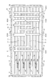
- FIG. 3 is a schematic cross-sectional explanatory view showing a state in which various types of workpieces having different lengths and widths are held on a fixed beam in the continuous heating furnace in the embodiment.
- detection means is provided at both the front end side and the rear end side of the cart in the transport direction of the workpiece, and the detection is provided at the position of the rear end side of the cart in the transport direction.
- an ITV camera is used as a detection means in the cart, and the ITV camera detects a state in which an object to be processed is held on a fixed beam while being inclined in the transport direction.
- the object to be processed which is held on the fixed beam in a state inclined in the conveying direction as described above, is held in the lift holding part of each cart, and the object to be processed is conveyed.
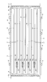
- a plurality of combustion devices 12 are provided on the side wall 11, and required in the conveying direction of the workpiece A on the furnace floor 13.
- Support members 14a are erected at intervals, and fixed beams 14 are provided on the support members 14a along the transport direction of the workpiece A.
- Such fixed beams 14 are transported in the transport direction of the workpiece A.
- a plurality of continuous heating furnaces 10 are provided in the width direction of the continuous heating furnace 10 at a predetermined interval.
- the loading door 15a provided at the carry-in port 15 of the continuous heating furnace 10 is opened, and the heating in the loading section 1 is performed.
- the workpiece A before processing is carried into the continuous heating furnace 10 through the carry-in port 15 so that the workpiece A is held on the fixed beam 14.
- the workpiece A thus held on the fixed beam 14 is heated in the continuous heating furnace 10 by the combustion device 12, and the workpiece A held on the fixed beam 14 is described later.
- the in-furnace transport device 20 transports the heat on the fixed beam 14 sequentially in the transport direction downstream side.
- the workpiece A held on the fixed beam 14 is sequentially transferred on the fixed beam 14 to the downstream side in the transfer direction by the in-furnace transfer device 20.
- the conveyance guide groove 17 along the conveyance direction of the workpiece A is penetrated through the hearth 13 of the continuous heating furnace 10 at a position where the fixed beam 14 does not overlap with the conveyance of the workpiece A.
- a plurality of continuous heating furnaces 10 are provided in the width direction of the continuous heating furnace 10 perpendicular to the direction with a required interval.
- the guide rails 21 along the transport direction of the workpiece A are made to correspond to the transport guide grooves 17 on the floor surface G below the hearth 13.
- a plurality of carts 22, which are self-propelled on each guide rail 21, are provided.
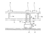
- the detection means 23 for detecting the position of the workpiece A held on the fixed beam 14 in the continuous heating furnace 10 at the position on the front end side in the conveyance direction of the workpiece A in FIG. Optical sensors and ITV cameras are provided.
- a pipe bent into a reverse groove shape is used, and cooling water is guided to a water channel 22c formed in the elevation holding portion 22b by a cooling means (not shown) such as a pump, and the elevation holding portion 22b. Is prevented from being overheated.
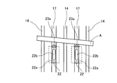
- the workpiece A held on the fixed beam 14 is sequentially transferred to the downstream side in the transfer direction on the fixed beam 14, as shown in FIG.
- the lifting and lowering holding portions 22b provided in each cart 22 are raised to a position above the fixed beam 14 by the lifting and lowering device 22a, and the workpiece A held on the fixed beam 14 is lifted and lowered. It is made to hold
- the cart 22 is caused to travel along the guide rail 21 in the conveying direction of the workpiece A in a state where the workpiece A is held by the lift holding portion 22b, and is shown in FIG.
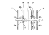
- the detection means 23 provided on the front end side of the cart 22 in the transport direction detects the previous workpiece A that has been transported first and held on the fixed beam 14 on the downstream side in the transport direction. The cart 22 is stopped at this position.
- the lifting / lowering holding part 22 b holding the workpiece A is lowered by the lifting / lowering device 22 a, and the lifting / lowering holding part 22 b is positioned below the fixed beam 14.
- the workpiece A held by the lifting / lowering holding portion 22b is held on the fixed beam 14 with a predetermined distance from the workpiece A.
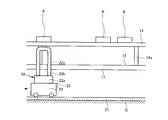
- the cart 22 is moved along the guide rail 21 in the direction opposite to the conveying direction of the workpiece A. As shown in FIG. 7, the cart 22 is moved to a position where the workpiece A to be conveyed next is detected by the detection means 23 provided on the cart 22. After that, as shown in FIG. 8, the cart 22 is moved in the conveying direction of the workpiece A to a position where the next workpiece A is appropriately held on the lift holding portion 22b. As described above, the lifting / lowering holding portion 22b is raised to a position above the fixed beam 14 by the lifting / lowering device 22a, and the next workpiece A is held by the lifting / lowering holding portion 22b. Repeatedly, the workpieces A held on the fixed beam 14 are sequentially transferred onto the fixed beam 14 on the downstream side in the transfer direction.
- the detection means 23 provided on the cart 22 detects the previous workpiece A positioned downstream in the transport direction and controls the traveling of the cart 22.
- the detection means 23 detects the previous workpiece A positioned downstream in the transport direction and controls the traveling of the cart 22.
- a control device (not shown) for controlling the traveling of the cart 22 can be provided, and the distance by which the cart 22 travels can be controlled by the control device in accordance with the width of the workpiece A in the transport direction.
- the position of each object A detected by the first to fourth detection means 23 provided in each of the first to fourth carts 22 is Output from the first to fourth detection means 23 to the storage means 30, and the storage means 30 stores the position and arrangement state of the workpieces A held on the fixed beam 14 in the continuous heating furnace 10. I try to let them.
- the above-mentioned memory is stored due to a power failure or the like while various types of workpieces A having different lengths and widths are held on the fixed beam 14 in the continuous heating furnace 10.
- the carts 22 are respectively moved along the guide rails 21 from the carry-in port 15 of the continuous heating furnace 10 to the carry-out port.
- each detection means 23 provided in each cart 22 travels and detects each workpiece A held on the fixed beam 14, and outputs the result to the storage means 30. To do.
- each cart 22 travels from the carry-in port 15 to the carry-out port 16 of the continuous heating furnace 10, and each object to be processed held on the fixed beam 14 by each detection means 23 provided in each cart 22.
- each detection means 23 provided in each cart 22.
- the difference in width between the object to be processed A4 and the object to be processed A3 can be detected by the respective detecting means 23, whereby there are two short objects to be processed A4 and objects to be processed A3 having different widths.
- each workpiece detected by each detector 23 provided in each cart 22 as described above is provided. Together with the result of the processed object A, the position and arrangement state of the processed objects A held on the fixed beam 14 can be reproduced more accurately.
- the detection means 23 for detecting the position of the workpiece A held on the fixed beam 14 is provided at a position on the front side in the transport direction of the workpiece A in each cart 22.
- the detection means 23 is also provided at a position on the rear end side in the transport direction of the workpiece A in each cart 22, and the cart 22 is arranged along the guide rail 21.
- the detection unit 23 provided at the position on the rear end side in the conveyance direction of the cart 22 causes the workpiece A positioned upstream in the conveyance direction to move. It can also be made to detect.
- a laser sensor or the like is used as the detecting means 23.
- the ITV camera 23a is provided in the cart 22, the ITV camera 23a is held on the fixed beam 14 in a wide range in the transport direction by the ITV camera 23a. This is also the case when the workpiece A is held on the fixed beam 14 while being inclined in the transport direction as shown in FIG. It is also possible to detect the inclination of the object to be processed A. Such detection can also be performed by installing a plurality of laser sensors on the cart 22.
Landscapes
- Engineering & Computer Science (AREA)
- Mechanical Engineering (AREA)
- General Engineering & Computer Science (AREA)
- Tunnel Furnaces (AREA)
- Heat Treatments In General, Especially Conveying And Cooling (AREA)
Applications Claiming Priority (2)
| Application Number | Priority Date | Filing Date | Title |
|---|---|---|---|
| JP2012157565A JP5843715B2 (ja) | 2012-07-13 | 2012-07-13 | 炉内搬送装置及び連続加熱炉 |
| JP2012-157565 | 2012-07-13 |
Publications (1)
| Publication Number | Publication Date |
|---|---|
| WO2014010316A1 true WO2014010316A1 (fr) | 2014-01-16 |
Family
ID=49915790
Family Applications (1)
| Application Number | Title | Priority Date | Filing Date |
|---|---|---|---|
| PCT/JP2013/064330 Ceased WO2014010316A1 (fr) | 2012-07-13 | 2013-05-23 | Dispositif de transport dans un four et four de chauffage continu |
Country Status (2)
| Country | Link |
|---|---|
| JP (1) | JP5843715B2 (fr) |
| WO (1) | WO2014010316A1 (fr) |
Citations (1)
| Publication number | Priority date | Publication date | Assignee | Title |
|---|---|---|---|---|
| JPS6237313A (ja) * | 1985-08-09 | 1987-02-18 | Chugai Ro Kogyo Kaisha Ltd | ウオ−キングビ−ム型鋼片加熱炉 |
Family Cites Families (1)
| Publication number | Priority date | Publication date | Assignee | Title |
|---|---|---|---|---|
| JP5769593B2 (ja) * | 2011-11-16 | 2015-08-26 | 中外炉工業株式会社 | 炉内搬送装置及び加熱炉 |
-
2012
- 2012-07-13 JP JP2012157565A patent/JP5843715B2/ja active Active
-
2013
- 2013-05-23 WO PCT/JP2013/064330 patent/WO2014010316A1/fr not_active Ceased
Patent Citations (1)
| Publication number | Priority date | Publication date | Assignee | Title |
|---|---|---|---|---|
| JPS6237313A (ja) * | 1985-08-09 | 1987-02-18 | Chugai Ro Kogyo Kaisha Ltd | ウオ−キングビ−ム型鋼片加熱炉 |
Also Published As
| Publication number | Publication date |
|---|---|
| JP5843715B2 (ja) | 2016-01-13 |
| JP2014020616A (ja) | 2014-02-03 |
Similar Documents
| Publication | Publication Date | Title |
|---|---|---|
| EP3418222B1 (fr) | Installation de stockage d'articles | |
| TWI752219B (zh) | 物品搬送設備 | |
| TWI602768B (zh) | Transfer device | |
| JP2007015780A (ja) | 物品収納設備 | |
| KR101504146B1 (ko) | 반송시스템 | |
| KR20170058393A (ko) | 퍼지 장치 및 퍼지 방법 | |
| KR102069587B1 (ko) | 이송대차 시스템 | |
| TW201604117A (zh) | 載具的搬運系統與搬運方法 | |
| JP2005089059A (ja) | 物品移載装置 | |
| JP2006056631A (ja) | 物品搬送装置 | |
| KR20120108962A (ko) | 물품 이송탑재 장치 및 이것을 구비한 스태커 크레인 | |
| JP5769593B2 (ja) | 炉内搬送装置及び加熱炉 | |
| JP2017048950A (ja) | 昇降設備及び搬送システム | |
| JP5743981B2 (ja) | 連続加熱炉 | |
| JP5843715B2 (ja) | 炉内搬送装置及び連続加熱炉 | |
| JP5534355B2 (ja) | 物品収納設備 | |
| JP4314521B2 (ja) | 物品搬送装置 | |
| JP5348978B2 (ja) | 車位置補正装置 | |
| JP2008285252A (ja) | 自動荷役車両およびその制御方法 | |
| KR101341428B1 (ko) | 반송 시스템 및 그 제어 방법 | |
| JP2008230843A (ja) | 搬送台車の制御方法 | |
| KR101489270B1 (ko) | 터치 스크린 패널용 기판이송장치 | |
| JP4399734B2 (ja) | 昇降式の物品搬送装置 | |
| JP6135402B2 (ja) | 搬送装置及び搬送設備 | |
| KR101504915B1 (ko) | 슬라브 가열장치 |
Legal Events
| Date | Code | Title | Description |
|---|---|---|---|
| 121 | Ep: the epo has been informed by wipo that ep was designated in this application |
Ref document number: 13816128 Country of ref document: EP Kind code of ref document: A1 |
|
| NENP | Non-entry into the national phase |
Ref country code: DE |
|
| 122 | Ep: pct application non-entry in european phase |
Ref document number: 13816128 Country of ref document: EP Kind code of ref document: A1 |