WO2014010399A1 - 膜電極接合体 - Google Patents
膜電極接合体 Download PDFInfo
- Publication number
- WO2014010399A1 WO2014010399A1 PCT/JP2013/067276 JP2013067276W WO2014010399A1 WO 2014010399 A1 WO2014010399 A1 WO 2014010399A1 JP 2013067276 W JP2013067276 W JP 2013067276W WO 2014010399 A1 WO2014010399 A1 WO 2014010399A1
- Authority
- WO
- WIPO (PCT)
- Prior art keywords
- electrolyte membrane
- gasket
- holes
- hole
- electrode assembly
- Prior art date
- Legal status (The legal status is an assumption and is not a legal conclusion. Google has not performed a legal analysis and makes no representation as to the accuracy of the status listed.)
- Ceased
Links
Images


Classifications
-
- H—ELECTRICITY
- H01—ELECTRIC ELEMENTS
- H01M—PROCESSES OR MEANS, e.g. BATTERIES, FOR THE DIRECT CONVERSION OF CHEMICAL ENERGY INTO ELECTRICAL ENERGY
- H01M8/00—Fuel cells; Manufacture thereof
- H01M8/02—Details
- H01M8/0271—Sealing or supporting means around electrodes, matrices or membranes
-
- H—ELECTRICITY
- H01—ELECTRIC ELEMENTS
- H01M—PROCESSES OR MEANS, e.g. BATTERIES, FOR THE DIRECT CONVERSION OF CHEMICAL ENERGY INTO ELECTRICAL ENERGY
- H01M8/00—Fuel cells; Manufacture thereof
- H01M8/02—Details
- H01M8/0271—Sealing or supporting means around electrodes, matrices or membranes
- H01M8/0273—Sealing or supporting means around electrodes, matrices or membranes with sealing or supporting means in the form of a frame
-
- H—ELECTRICITY
- H01—ELECTRIC ELEMENTS
- H01M—PROCESSES OR MEANS, e.g. BATTERIES, FOR THE DIRECT CONVERSION OF CHEMICAL ENERGY INTO ELECTRICAL ENERGY
- H01M8/00—Fuel cells; Manufacture thereof
- H01M8/10—Fuel cells with solid electrolytes
-
- H—ELECTRICITY
- H01—ELECTRIC ELEMENTS
- H01M—PROCESSES OR MEANS, e.g. BATTERIES, FOR THE DIRECT CONVERSION OF CHEMICAL ENERGY INTO ELECTRICAL ENERGY
- H01M8/00—Fuel cells; Manufacture thereof
- H01M8/10—Fuel cells with solid electrolytes
- H01M8/1016—Fuel cells with solid electrolytes characterised by the electrolyte material
- H01M8/1018—Polymeric electrolyte materials
-
- H—ELECTRICITY
- H01—ELECTRIC ELEMENTS
- H01M—PROCESSES OR MEANS, e.g. BATTERIES, FOR THE DIRECT CONVERSION OF CHEMICAL ENERGY INTO ELECTRICAL ENERGY
- H01M8/00—Fuel cells; Manufacture thereof
- H01M8/24—Grouping of fuel cells, e.g. stacking of fuel cells
- H01M8/241—Grouping of fuel cells, e.g. stacking of fuel cells with solid or matrix-supported electrolytes
- H01M8/242—Grouping of fuel cells, e.g. stacking of fuel cells with solid or matrix-supported electrolytes comprising framed electrodes or intermediary frame-like gaskets
-
- H—ELECTRICITY
- H01—ELECTRIC ELEMENTS
- H01M—PROCESSES OR MEANS, e.g. BATTERIES, FOR THE DIRECT CONVERSION OF CHEMICAL ENERGY INTO ELECTRICAL ENERGY
- H01M8/00—Fuel cells; Manufacture thereof
- H01M8/10—Fuel cells with solid electrolytes
- H01M2008/1095—Fuel cells with polymeric electrolytes
-
- H—ELECTRICITY
- H01—ELECTRIC ELEMENTS
- H01M—PROCESSES OR MEANS, e.g. BATTERIES, FOR THE DIRECT CONVERSION OF CHEMICAL ENERGY INTO ELECTRICAL ENERGY
- H01M8/00—Fuel cells; Manufacture thereof
- H01M8/02—Details
- H01M8/0271—Sealing or supporting means around electrodes, matrices or membranes
- H01M8/028—Sealing means characterised by their material
- H01M8/0284—Organic resins; Organic polymers
-
- Y—GENERAL TAGGING OF NEW TECHNOLOGICAL DEVELOPMENTS; GENERAL TAGGING OF CROSS-SECTIONAL TECHNOLOGIES SPANNING OVER SEVERAL SECTIONS OF THE IPC; TECHNICAL SUBJECTS COVERED BY FORMER USPC CROSS-REFERENCE ART COLLECTIONS [XRACs] AND DIGESTS
- Y02—TECHNOLOGIES OR APPLICATIONS FOR MITIGATION OR ADAPTATION AGAINST CLIMATE CHANGE
- Y02E—REDUCTION OF GREENHOUSE GAS [GHG] EMISSIONS, RELATED TO ENERGY GENERATION, TRANSMISSION OR DISTRIBUTION
- Y02E60/00—Enabling technologies; Technologies with a potential or indirect contribution to GHG emissions mitigation
- Y02E60/30—Hydrogen technology
- Y02E60/50—Fuel cells
Definitions
- the present invention relates to a membrane electrode assembly.
- a membrane electrode assembly (MEA: membrane electrode assembly) included in a single cell of a fuel cell includes a polymer electrolyte membrane in which a catalyst layer is arranged, and a frame-like gasket arranged on both sides of the polymer electrolyte membrane.
- the gasket is positioned so as to surround the catalyst layer of the polymer electrolyte membrane, and has a function of preventing the fuel gas and the oxidant gas supplied to the catalyst layer from leaking to the outside.
- the present invention has been made to solve the above-described problems associated with the prior art, and an object thereof is to provide a membrane electrode assembly in which external leakage of fuel gas and oxidant gas supplied to a catalyst layer is suppressed.
- the present invention for achieving the above object is a membrane electrode assembly having an electrolyte membrane and frame-shaped first and second gaskets disposed on both surfaces of the electrolyte membrane.
- the first and second gaskets are located on an outer peripheral edge of the electrolyte membrane and are opposed to the electrolyte membrane; a joint located on the outer side of the outer peripheral edge and bonded to each other;
- Have The overlap portion and the joint portion have a through hole extending in the thickness direction of the electrolyte membrane, and an opening ratio of the through hole of the overlap portion is larger than an opening ratio of the through hole of the joint portion.
- the first and second gaskets since the overlap portion and the joint portion of the first and second gaskets have through holes extending in the thickness direction of the electrolyte membrane, the first and second gaskets are arranged on the electrolyte membrane and bonded together. After that, it is possible to remove the bubbles remaining in the gaps and the overlap portions of the joints via the through holes.
- the opening ratio of the through hole in the overlap portion is larger than the opening ratio of the through hole in the joint portion, the through hole in the overlap portion is sufficient even if the outer peripheral edge of the electrolyte membrane is interposed. Demonstrates air bubble removal function.
- the overlap portion and the outer peripheral edge of the electrolyte membrane are sufficiently bonded to each other as in the case of the joint portion of the first gasket and the joint portion of the second gasket where the polymer electrolyte membrane is not disposed. Residual air bubbles are suppressed. Therefore, it is possible to provide a membrane electrode assembly in which external leakage of fuel gas and oxidant gas supplied to the catalyst layer is suppressed.
- FIG. 1 is a cross-sectional view for explaining a cell structure of a fuel cell according to an embodiment of the present invention
- FIGS. 2 and 3 are arranged on both surfaces of the outer periphery of the polymer electrolyte membrane shown in FIG. It is the top view and sectional drawing for demonstrating a 1st and 2nd gasket.
- the single cell 10 is applied to a polymer electrolyte fuel cell (PEFC) or the like using hydrogen as a fuel, and has a membrane electrode assembly 20 and separators 80 and 85.
- PEFC polymer electrolyte fuel cell
- the single cell 10 further includes a cooling plate 90, and a refrigerant flow through which a refrigerant for cooling the single cell 10 flows by a groove 92 provided in the cooling plate 90.
- a road is constructed.
- the membrane electrode assembly 20 includes a polymer electrolyte membrane 30, catalyst layers 32 and 33, gas diffusion layers (GDLs) 35 and 36, a first gasket 40 and a second gasket 60.
- GDLs gas diffusion layers
- the catalyst layer 32 is an anode catalyst layer that includes a catalyst component, a conductive catalyst carrier that supports the catalyst component, and a polymer electrolyte, and in which a hydrogen oxidation reaction proceeds. It is arranged on the side.
- the catalyst layer 33 is a cathode catalyst layer that includes a catalyst component, a conductive catalyst carrier that supports the catalyst component, and a polymer electrolyte, and in which the oxygen reduction reaction proceeds. It is arranged on the side.
- the polymer electrolyte membrane 30 has a function of selectively permeating protons generated in the catalyst layer 32 to the catalyst layer 33 and does not mix the fuel gas supplied to the anode side and the oxidant gas supplied to the cathode side. It functions as a partition wall.
- the gas diffusion layer 35 is an anode gas diffusion layer for dispersing the fuel gas supplied to the anode side, and is located between the separator 80 and the catalyst layer 32.
- the gas diffusion layer 36 is a cathode gas diffusion layer for dispersing the oxidant gas supplied to the cathode side, and is located between the separator 85 and the catalyst layer 33.
- the first and second gaskets 40 and 60 have a frame shape as shown in FIGS. 2 and 3 and are arranged on both surfaces of the outer peripheral portion of the polymer electrolyte membrane 30.
- the gasket 40 is positioned so as to surround the catalyst layer 32 and the gas diffusion layer 35, and has a function of preventing the fuel gas supplied to the catalyst layer 32 from leaking to the outside.
- the gasket 60 is positioned so as to surround the catalyst layer 33 and the gas diffusion layer 36, and has a function of preventing the oxidant gas supplied to the catalyst layer 33 from leaking to the outside.
- the separators 80 and 85 have a function of electrically connecting the single cells 10 in series and a function of a partition that blocks fuel gas, oxidant gas, and refrigerant from each other, and have substantially the same shape as the membrane electrode assembly 20.
- it is formed by pressing a stainless steel plate.
- the stainless steel plate is preferable in that it can be easily subjected to complicated machining and has good conductivity, and can be coated with a corrosion-resistant coating as necessary.
- the separator 80 is an anode separator that is disposed on the anode side of the membrane electrode assembly 20, and is opposed to the catalyst layer 32 and constitutes a groove portion 82 that constitutes a gas flow path positioned between the membrane electrode assembly 20 and the separator 80.
- Have The groove (gas flow path) 82 is used for supplying the fuel gas to the catalyst layer 32.
- the separator 85 is a cathode separator disposed on the cathode side of the membrane electrode assembly 20, and is opposed to the catalyst layer 33 and constitutes a groove portion 87 that constitutes a gas flow path located between the membrane electrode assembly 20 and the separator 85.
- Have The groove (gas flow path) 87 is used to supply the oxidant gas to the catalyst layer 33.
- the polymer electrolyte membrane 30 is a porous polymer electrolyte membrane made of a perfluorocarbon sulfonic acid polymer, a porous resin membrane having a sulfonic acid group, and a porous material impregnated with an electrolyte component such as phosphoric acid or ionic liquid.
- a shaped film can be applied.
- the perfluorocarbon sulfonic acid polymer is, for example, Nafion (registered trademark, manufactured by DuPont), Aciplex (registered trademark, manufactured by Asahi Kasei Co., Ltd.), and Flemion (registered trademark, manufactured by Asahi Glass Co., Ltd.).
- the porous film is made of, for example, polytetrafluoroethylene (PTFE) or polyvinylidene fluoride (PVDF).
- the thickness of the polymer electrolyte membrane 30 is not particularly limited, but is preferably 5 to 300 ⁇ m, more preferably 10 to 200 ⁇ m from the viewpoint of strength, durability, and output characteristics.
- the catalyst component used for the catalyst layer (cathode catalyst layer) 35 is not particularly limited as long as it has a catalytic action in the oxygen reduction reaction.
- the catalyst component used for the catalyst layer (anode catalyst layer) 34 is not particularly limited as long as it has a catalytic action for the oxidation reaction of hydrogen.
- catalyst components include, for example, platinum, ruthenium, iridium, rhodium, palladium, osmium, tungsten, lead, iron, chromium, cobalt, nickel, manganese, vanadium, molybdenum, gallium, aluminum and other metals, and alloys thereof. Etc. are selected. In order to improve catalytic activity, poisoning resistance to carbon monoxide, heat resistance, etc., the catalyst component preferably contains at least platinum.
- the catalyst components applied to the cathode catalyst layer and the anode catalyst layer need not be the same, and can be changed as appropriate.
- the conductive carrier of the catalyst used for the catalyst layers 32 and 33 is particularly limited as long as it has a specific surface area for supporting the catalyst component in a desired dispersed state and sufficient electronic conductivity as a current collector.
- the main component is preferably carbon particles.
- the carbon particles are composed of, for example, carbon black, activated carbon, coke, natural graphite, and artificial graphite.
- the polymer electrolyte used for the catalyst layers 32 and 33 is not particularly limited as long as it is a substance having at least high proton conductivity.
- a fluorine-based electrolyte containing a fluorine atom in all or part of the polymer skeleton or a polymer A hydrocarbon-based electrolyte that does not contain a fluorine atom in the skeleton is applicable.
- the polymer electrolyte used for the catalyst layers 32 and 33 may be the same as or different from the polymer electrolyte used for the polymer electrolyte membrane 30, but the catalyst layers 32 and 33 adhere to the polymer electrolyte membrane 30. From the viewpoint of improving the properties, it is preferable that they are the same.
- the gas diffusion layers 35 and 36 are configured by using, as a base material, a sheet-like material having conductivity and porosity such as a carbon woven fabric such as glassy carbon, a paper-like paper body, a felt, and a nonwoven fabric.
- the thickness of the substrate is not particularly limited, but is preferably 30 to 500 ⁇ m from the viewpoint of mechanical strength and permeability such as gas and water.
- the gas diffusion layers 35 and 36 preferably contain a water repellent in the base material from the viewpoint of water repellency and suppression of the flooding phenomenon.
- water repellent examples include fluorine-based polymer materials such as PTFE, PVDF, polyhexafluoropropylene, tetrafluoroethylene-hexafluoropropylene copolymer (FEP), polypropylene, and polyethylene.
- fluorine-based polymer materials such as PTFE, PVDF, polyhexafluoropropylene, tetrafluoroethylene-hexafluoropropylene copolymer (FEP), polypropylene, and polyethylene.
- the first and second gaskets 40 and 60 are made of, for example, a rubber material, a fluorine-based polymer material, or a thermoplastic resin.
- the rubber material include fluorine rubber, silicon rubber, ethylene propylene rubber (EPDM), and polyisobutylene rubber.
- the fluorine-based polymer material include PTFE, PVDF, polyhexafluoropropylene, and FEP.
- the thermoplastic resin is polyolefin or polyester.
- the polyester is, for example, polyethylene naphthalate (PEN).
- the thickness of the first and second gaskets 40 and 60 is not particularly limited, but is preferably 50 ⁇ m to 2 mm, and more preferably 100 ⁇ m to 1 mm.
- the separators 80 and 85 are not limited to the form of the stainless steel plate, and other metal materials (for example, aluminum plate or clad material), carbon such as dense carbon graphite or carbon plate can also be applied. When carbon is applied, the grooves 82 and 87 can be formed by cutting or screen printing.
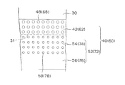
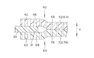
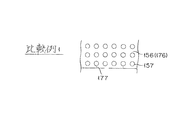
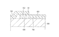
- FIGS. 4 and 5 are a plan view and a cross-sectional view for explaining the through holes of the first and second gaskets shown in FIGS. 2 and 3, and FIGS. 6 and 7 are views showing the joint shown in FIG. It is a top view for demonstrating the comparative example 1 and the comparative example 2 which concern.
- the first and second gaskets 40, 60 have overlap portions 42, 62 and joint portions 52, 72.
- the overlap portions 42 and 62 are located on the outer peripheral edge 31 of the polymer electrolyte membrane 30, are opposed to the polymer electrolyte membrane 30, and are provided with through holes 48 and 68.
- the joint portions 52 and 72 are located outside the outer peripheral edge 31 of the polymer electrolyte membrane 30 and bonded to each other, and the inner portions 54 and 74 where the through holes 58 and 78 are disposed, and the inner portions 54 and 74.
- outer portions 56 and 76 which are located on the outer side and in which no through holes are arranged.
- the joint portions 52 and 72 have a function of suppressing the first and second gaskets 40 and 60 from peeling from the polymer electrolyte membrane 30.
- the through-holes 48 and 68 and the through-holes 58 and 78 are fine and extend in the thickness direction T of the polymer electrolyte membrane 30, and the influence on the direction orthogonal to the thickness direction T is suppressed.
- the opening ratios of the through holes 48 and 68 of the overlap parts 42 and 62 are set to be larger than the opening ratios of the through holes 58 and 78 of the joint parts 52 and 72.
- the opening ratio of the through hole is adjusted by changing the hole diameter (size) of the through hole. That is, the hole diameters of the through holes 48 and 68 of the overlap parts 42 and 62 are made larger than the hole diameters of the through holes 58 and 78 of the joint parts 52 and 72, thereby the through holes 48 of the overlap parts 42 and 62. , 68 can easily be made larger than the aperture ratio of the through holes 58, 78 of the joint portions 52, 72.
- the opening ratio of the through hole is preferably 20% or less from the viewpoint of rigidity, and preferably 0.2% or more from the viewpoint of the effect of the through hole.
- the aperture ratio is about 20% when the pitch interval is set to twice the hole diameter of the through holes, and the aperture ratio is set when the pitch interval is set to 10 times the hole diameter of the through holes.
- the aperture ratio is about 0.001 to 0.01%.
- the pitch interval is preferably 2 to 100 times the hole diameter, and when the hole diameter of the through hole is 10 to 100 ⁇ m, the pitch interval is 2 to 10 times the hole diameter. It is preferable.
- the method for forming the through hole is not particularly limited, and a laser, a mold, or the like can be used.
- a laser for example, the position and size of the through hole are adjusted by controlling the laser output, spot diameter, scanning timing, and the like.
- the cavity surface is configured like a sword mountain with fine protrusions, and it is possible to provide melting holes by pressing against the gasket material and heating, and the position and size of the protrusions etc. Is changed, the position and size of the through hole are adjusted.
- the catalyst layers 32 and 33 can be formed after the first and second gaskets 40 and 60 are disposed and pasted as needed, or can be formed in advance on the polymer electrolyte membrane 30. .
- the gas diffusion layers 35 and 36 can be arranged integrally with the catalyst layers 32 and 33, or can be arranged separately when the membrane electrode assembly 20 is laminated, for example.
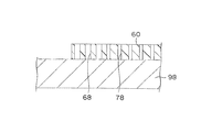
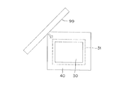
- FIG. 9, FIG. 10 and FIG. 11 are cross-sectional views for explaining the arrangement of the second gasket, cross-sectional views for explaining the arrangement of the polymer electrolyte membrane, and for explaining the arrangement of the first gasket.
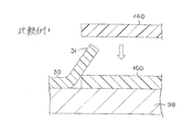
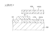
- FIG. 12 and FIG. 13 are sectional views and plan views for explaining bubble removal by a squeegee. It is sectional drawing for demonstrating the comparative example 1 and the comparative example 2 which concern on arrangement
- the mounting table 98 is made of a porous member, and is connected to an external vacuum source (not shown), and is configured to be able to suck an arranged object.
- the polymer electrolyte membrane 30 is placed on the mounting table 98 and bonded, and the outer peripheral edge 31 of the polymer electrolyte membrane 30 is positioned so as to overlap the second gasket 60. Thereby, the overlap part 62 is formed in the second gasket 60. At this time, the outer peripheral edge 31 of the polymer electrolyte membrane 30 is sucked into the mounting table 98 through the through hole 68 provided in the overlap portion 62 of the second gasket 60. For example, the polymer electrolyte membrane 30 The turning of the outer peripheral edge 31 is suppressed.
- the first gasket 40 is placed on the mounting table 98 and bonded, and the first gasket 40 is positioned so as to overlap the outer peripheral edge 31 of the polymer electrolyte membrane 30. Thereby, the overlap part 62 and the joining part 52 are formed in the first gasket 40, and the joining part 72 is formed in the second gasket 60.
- the opening ratios of the through holes 48 and 68 of the overlap parts 42 and 62 are set larger than the opening ratios of the through holes 58 and 78 of the joint parts 52 and 72, the penetrations of the overlap parts 42 and 62 are achieved.
- the holes 48 and 68 exhibit a sufficient bubble removing function even when the polymer electrolyte membrane 30 is interposed. Thereby, like the case of the junction parts 52 and 72 where the polymer electrolyte membrane 30 is not disposed, the overlap parts 42 and 62 and the outer peripheral edge 31 of the polymer electrolyte membrane 30 are sufficiently bonded, Residual air bubbles are suppressed.
- the remaining bubbles form a gas leak passage
- the protrusions formed by the remaining bubbles are located between the first and second gaskets 40, 60 and the separators 80, 85. Therefore, it is possible to prevent the fuel gas and the oxidant gas supplied to the catalyst layers 32 and 33 from leaking to the outside. The That is, it is possible to provide the membrane electrode assembly 20 in which external leakage of fuel gas and oxidant gas supplied to the catalyst layer is suppressed.
- the suction is performed up to the upper surface of the first gasket 140A. (Vacuum) is affected, and it is difficult to accurately release the first gasket 140A toward the outer peripheral edge 31 (second gasket 160A) of the polymer electrolyte membrane 30.
- air bubbles can be removed with a squeegee after the first gasket is placed.
- the first and second gaskets 40 and 60 are pressed by moving the squeegee 99 while suctioning by the mounting table 98.
- the pressing by the squeegee 99 causes bubbles (biting air) remaining in the gap S between the joint portions 52 and 72 and the overlap portions 42 and 62 to pass through the through holes 48 and 68 of the overlap portions 42 and 62 and the joint portion 52. , 72 through the through holes 58, 78.
- the squeegee 99 is made of plastic or metal.
- FIG. 14 is a plan view for explaining a modification according to the embodiment of the present invention.
- the aperture ratios of the through holes 48, 58, 68, 78 can be adjusted by changing the density of the through holes 48, 58, 68, 78.
- the aperture ratio is adjusted by making the density of the through holes 48 and 68 of the overlap portions 42 and 62 larger than the density of the through holes 58 and 78 of the joint portions 52 and 72. Can be easily achieved.
- the overlap portion and the joint portion of the first and second gaskets have through holes extending in the thickness direction of the electrolyte membrane, and therefore the first and second gaskets are used.
- the first and second gaskets are used.
- the overlap portion and the outer peripheral edge of the electrolyte membrane are sufficiently bonded to each other as in the case of the joint portion of the first gasket and the joint portion of the second gasket where the polymer electrolyte membrane is not disposed. Residual air bubbles are suppressed. Therefore, it is possible to provide a membrane electrode assembly in which external leakage of fuel gas and oxidant gas supplied to the catalyst layer is suppressed.
- the opening ratio of the through holes can be adjusted by changing the size of the through holes or the density of the through holes. For example, by making the size of the through hole in the overlap part larger than the size of the through hole in the joint part, or by making the density of the through hole in the overlap part larger than the density of the through hole in the joint part, It is easily achieved that the opening ratio of the through-holes is larger than the opening ratio of the through-holes of the joint portion.
- the fuel cell can be constituted by a polymer electrolyte fuel cell using methanol as a fuel, or can be applied as a stationary power source.
- the polymer electrolyte fuel cell using methanol as a fuel is a direct methanol fuel cell (DMFC), a micro fuel cell (passive DMFC), or the like.
- ethanol 1-propanol, 2-propanol, primary butanol, secondary butanol, tertiary butanol, dimethyl ether, diethyl ether, ethylene glycol, diethylene glycol, etc. can be applied. It is.
Landscapes
- Life Sciences & Earth Sciences (AREA)
- Engineering & Computer Science (AREA)
- Manufacturing & Machinery (AREA)
- Sustainable Development (AREA)
- Sustainable Energy (AREA)
- Chemical & Material Sciences (AREA)
- Chemical Kinetics & Catalysis (AREA)
- Electrochemistry (AREA)
- General Chemical & Material Sciences (AREA)
- Fuel Cell (AREA)
Abstract
Description
第1ガスケットの配置に係る比較例1および比較例2を説明するための断面図である。
20 膜電極接合体、
30 高分子電解質膜、
31 外周縁、
32,33 触媒層、
35,36 ガス拡散層、
40,140,140A 第1ガスケット、
42 オーバーラップ部、
48 貫通孔、
52 接合部、
54 内側部、
56 外側部、
58 貫通孔、
60,160,160A 第2ガスケット、
62 オーバーラップ部、
68 貫通孔、
72 接合部、
74 内側部、
76 外側部、
78 貫通孔、
80,85 セパレータ、
82,87 溝部、
90 冷却板、
92 溝部、
98 載置台、
99 スキージ、
156,176 外側部、
157,158,178 貫通孔、
177 クラック、
T 厚さ方向、
S 隙間。
Claims (4)
- 電解質膜と、
前記電解質膜の両面に配置される枠状の第1および第2ガスケットを有し、
前記第1および第2ガスケットは、
前記電解質膜の外周縁に位置し、前記電解質膜に対向しているオーバーラップ部と、
前記外周縁の外側に位置し、互いに接着している接合部と、を有し、
前記オーバーラップ部および前記接合部は、前記電解質膜の厚さ方向に延びる貫通孔を有し、
前記オーバーラップ部の貫通孔の開口率は、前記接合部の貫通孔の開口率より大きい、膜電極接合体。 - 前記オーバーラップ部の貫通孔のサイズは、前記接合部の貫通孔のサイズより大きい請求項1に記載の膜電極接合体。
- 前記オーバーラップ部の貫通孔の密度は、前記接合部の貫通孔の密度より大きい請求項1又は請求項2に記載の膜電極接合体。
- 前記接合部は、前記貫通孔が配置される内側部と、前記内側部の外側に位置し、前記貫通孔が配置されていない外側部と、を有する請求項1~3のいずれか1項に記載の膜電極接合体。
Priority Applications (5)
| Application Number | Priority Date | Filing Date | Title |
|---|---|---|---|
| CN201380036242.XA CN104428932B (zh) | 2012-07-10 | 2013-06-24 | 膜电极接合体 |
| EP13816315.9A EP2874219B1 (en) | 2012-07-10 | 2013-06-24 | Membrane electrode assembly |
| JP2014524716A JP5854139B2 (ja) | 2012-07-10 | 2013-06-24 | 膜電極接合体 |
| CA2878834A CA2878834C (en) | 2012-07-10 | 2013-06-24 | Membrane electrode assembly |
| US14/413,511 US9219282B2 (en) | 2012-07-10 | 2013-06-24 | Membrane electrode assembly |
Applications Claiming Priority (2)
| Application Number | Priority Date | Filing Date | Title |
|---|---|---|---|
| JP2012-154961 | 2012-07-10 | ||
| JP2012154961 | 2012-07-10 |
Publications (1)
| Publication Number | Publication Date |
|---|---|
| WO2014010399A1 true WO2014010399A1 (ja) | 2014-01-16 |
Family
ID=49915865
Family Applications (1)
| Application Number | Title | Priority Date | Filing Date |
|---|---|---|---|
| PCT/JP2013/067276 Ceased WO2014010399A1 (ja) | 2012-07-10 | 2013-06-24 | 膜電極接合体 |
Country Status (6)
| Country | Link |
|---|---|
| US (1) | US9219282B2 (ja) |
| EP (1) | EP2874219B1 (ja) |
| JP (1) | JP5854139B2 (ja) |
| CN (1) | CN104428932B (ja) |
| CA (1) | CA2878834C (ja) |
| WO (1) | WO2014010399A1 (ja) |
Cited By (3)
| Publication number | Priority date | Publication date | Assignee | Title |
|---|---|---|---|---|
| JP2014072107A (ja) * | 2012-09-28 | 2014-04-21 | Dainippon Printing Co Ltd | 補強材付き触媒層−電解質膜積層体、固体高分子形燃料電池、及び、補強材付き触媒層−電解質膜積層体の製造方法 |
| JP2018185977A (ja) * | 2017-04-26 | 2018-11-22 | 株式会社Soken | 燃料電池 |
| JP2019185922A (ja) * | 2018-04-04 | 2019-10-24 | トヨタ自動車株式会社 | 燃料電池セルの製造方法 |
Families Citing this family (1)
| Publication number | Priority date | Publication date | Assignee | Title |
|---|---|---|---|---|
| DE102021212401A1 (de) * | 2021-11-03 | 2023-05-04 | Robert Bosch Gesellschaft mit beschränkter Haftung | Membran-Elektroden-Einheit für eine elektrochemische Zelle und Verfahren zum Herstellen einer Membran-Elektroden-Einheit |
Citations (7)
| Publication number | Priority date | Publication date | Assignee | Title |
|---|---|---|---|---|
| JPH07501417A (ja) * | 1991-06-04 | 1995-02-09 | バラード パワー システムズ インコーポレイティド | 電気化学的燃料電池のガスケット使用膜電極アセンブリー |
| JP2005302526A (ja) * | 2004-04-12 | 2005-10-27 | Asahi Glass Co Ltd | 固体高分子電解質膜及び固体高分子電解質膜を有する膜電極接合体 |
| JP2006100266A (ja) * | 2004-08-30 | 2006-04-13 | Asahi Glass Co Ltd | 固体高分子電解質膜電極接合体及び固体高分子形燃料電池 |
| JP2006331700A (ja) * | 2005-05-23 | 2006-12-07 | Toyota Motor Corp | 燃料電池 |
| JP2010115663A (ja) * | 2008-11-11 | 2010-05-27 | Nissan Motor Co Ltd | 基材の接合方法及び基材の接合装置 |
| WO2011089008A1 (en) * | 2010-01-21 | 2011-07-28 | W.L. Gore & Associates Gmbh | Five-layer membrane electrode assembly with attached border and method of making same |
| JP4898221B2 (ja) | 2002-12-27 | 2012-03-14 | リンテック株式会社 | 粘着シートおよびその製造方法 |
Family Cites Families (5)
| Publication number | Priority date | Publication date | Assignee | Title |
|---|---|---|---|---|
| US7226686B2 (en) * | 2001-04-23 | 2007-06-05 | Nok Corporation | Fuel cell and method of manufacturing the fuel cell |
| US20050095490A1 (en) * | 2003-10-31 | 2005-05-05 | Mittelstadt Laurie S. | Fuel cell assembly gasket for fuel containment |
| EP1798794B1 (en) | 2004-08-30 | 2011-10-19 | Asahi Glass Company, Limited | Membrane electrode assembly for solid polymer fuel cell and solid polymer fuel cell |
| JP2007335353A (ja) * | 2006-06-19 | 2007-12-27 | Toyota Motor Corp | 燃料電池 |
| US7732083B2 (en) * | 2006-12-15 | 2010-06-08 | 3M Innovative Properties Company | Gas diffusion layer incorporating a gasket |
-
2013
- 2013-06-24 CA CA2878834A patent/CA2878834C/en not_active Expired - Fee Related
- 2013-06-24 CN CN201380036242.XA patent/CN104428932B/zh not_active Expired - Fee Related
- 2013-06-24 US US14/413,511 patent/US9219282B2/en not_active Expired - Fee Related
- 2013-06-24 EP EP13816315.9A patent/EP2874219B1/en not_active Not-in-force
- 2013-06-24 JP JP2014524716A patent/JP5854139B2/ja not_active Expired - Fee Related
- 2013-06-24 WO PCT/JP2013/067276 patent/WO2014010399A1/ja not_active Ceased
Patent Citations (7)
| Publication number | Priority date | Publication date | Assignee | Title |
|---|---|---|---|---|
| JPH07501417A (ja) * | 1991-06-04 | 1995-02-09 | バラード パワー システムズ インコーポレイティド | 電気化学的燃料電池のガスケット使用膜電極アセンブリー |
| JP4898221B2 (ja) | 2002-12-27 | 2012-03-14 | リンテック株式会社 | 粘着シートおよびその製造方法 |
| JP2005302526A (ja) * | 2004-04-12 | 2005-10-27 | Asahi Glass Co Ltd | 固体高分子電解質膜及び固体高分子電解質膜を有する膜電極接合体 |
| JP2006100266A (ja) * | 2004-08-30 | 2006-04-13 | Asahi Glass Co Ltd | 固体高分子電解質膜電極接合体及び固体高分子形燃料電池 |
| JP2006331700A (ja) * | 2005-05-23 | 2006-12-07 | Toyota Motor Corp | 燃料電池 |
| JP2010115663A (ja) * | 2008-11-11 | 2010-05-27 | Nissan Motor Co Ltd | 基材の接合方法及び基材の接合装置 |
| WO2011089008A1 (en) * | 2010-01-21 | 2011-07-28 | W.L. Gore & Associates Gmbh | Five-layer membrane electrode assembly with attached border and method of making same |
Non-Patent Citations (1)
| Title |
|---|
| See also references of EP2874219A4 * |
Cited By (4)
| Publication number | Priority date | Publication date | Assignee | Title |
|---|---|---|---|---|
| JP2014072107A (ja) * | 2012-09-28 | 2014-04-21 | Dainippon Printing Co Ltd | 補強材付き触媒層−電解質膜積層体、固体高分子形燃料電池、及び、補強材付き触媒層−電解質膜積層体の製造方法 |
| JP2018185977A (ja) * | 2017-04-26 | 2018-11-22 | 株式会社Soken | 燃料電池 |
| JP2019185922A (ja) * | 2018-04-04 | 2019-10-24 | トヨタ自動車株式会社 | 燃料電池セルの製造方法 |
| JP6996396B2 (ja) | 2018-04-04 | 2022-01-17 | トヨタ自動車株式会社 | 燃料電池セルの製造方法 |
Also Published As
| Publication number | Publication date |
|---|---|
| JP5854139B2 (ja) | 2016-02-09 |
| JPWO2014010399A1 (ja) | 2016-06-20 |
| CN104428932A (zh) | 2015-03-18 |
| EP2874219B1 (en) | 2016-11-30 |
| EP2874219A1 (en) | 2015-05-20 |
| EP2874219A4 (en) | 2015-07-22 |
| US9219282B2 (en) | 2015-12-22 |
| CA2878834C (en) | 2016-01-05 |
| CA2878834A1 (en) | 2014-01-16 |
| CN104428932B (zh) | 2016-04-20 |
| US20150188151A1 (en) | 2015-07-02 |
Similar Documents
| Publication | Publication Date | Title |
|---|---|---|
| US9331345B2 (en) | Bonded sheet and sheet-member bonding method | |
| JP4882314B2 (ja) | 電解質膜−電極接合体およびその製造方法 | |
| JP5326189B2 (ja) | 電解質膜−電極接合体およびその製造方法 | |
| JP2007095669A (ja) | 電解質膜−電極接合体 | |
| CN106457869B (zh) | 金属掩模及丝网印刷装置 | |
| JP5854139B2 (ja) | 膜電極接合体 | |
| JP2006338938A (ja) | 電解質膜−電極接合体およびその製造方法 | |
| JPWO2014010398A1 (ja) | 燃料電池用電解質膜の把持装置 | |
| JP2006338943A (ja) | 電解質膜−電極接合体 | |
| JP2019083113A (ja) | 電極触媒層、膜電極接合体及び固体高分子形燃料電池 | |
| JP7307109B2 (ja) | ガス拡散層付膜電極接合体およびその製造方法 | |
| JP4852894B2 (ja) | 電解質膜−電極接合体の製造方法 | |
| JP2014120368A (ja) | 燃料電池とその製造方法 | |
| JP5403491B2 (ja) | 膜電極接合体及びその製造方法 | |
| JP2006338942A (ja) | 電解質膜−電極接合体、および、燃料電池 | |
| JP2006338941A (ja) | 電解質膜−電極接合体 | |
| JP2006338937A (ja) | 電解質膜−電極接合体の製造方法 | |
| JP2006338940A (ja) | 電解質膜−電極接合体 |
Legal Events
| Date | Code | Title | Description |
|---|---|---|---|
| WWE | Wipo information: entry into national phase |
Ref document number: 201380036242.X Country of ref document: CN |
|
| 121 | Ep: the epo has been informed by wipo that ep was designated in this application |
Ref document number: 13816315 Country of ref document: EP Kind code of ref document: A1 |
|
| ENP | Entry into the national phase |
Ref document number: 2014524716 Country of ref document: JP Kind code of ref document: A |
|
| WWE | Wipo information: entry into national phase |
Ref document number: 14413511 Country of ref document: US |
|
| ENP | Entry into the national phase |
Ref document number: 2878834 Country of ref document: CA |
|
| NENP | Non-entry into the national phase |
Ref country code: DE |
|
| REEP | Request for entry into the european phase |
Ref document number: 2013816315 Country of ref document: EP |
|
| WWE | Wipo information: entry into national phase |
Ref document number: 2013816315 Country of ref document: EP |