WO2014010540A1 - 空洞管の研磨用電極とそれを用いた電解研磨方法 - Google Patents
空洞管の研磨用電極とそれを用いた電解研磨方法 Download PDFInfo
- Publication number
- WO2014010540A1 WO2014010540A1 PCT/JP2013/068593 JP2013068593W WO2014010540A1 WO 2014010540 A1 WO2014010540 A1 WO 2014010540A1 JP 2013068593 W JP2013068593 W JP 2013068593W WO 2014010540 A1 WO2014010540 A1 WO 2014010540A1
- Authority
- WO
- WIPO (PCT)
- Prior art keywords
- electrode
- hollow tube
- polishing
- blade
- storage cylinder
- Prior art date
- Legal status (The legal status is an assumption and is not a legal conclusion. Google has not performed a legal analysis and makes no representation as to the accuracy of the status listed.)
- Ceased
Links
Images





Classifications
-
- C—CHEMISTRY; METALLURGY
- C25—ELECTROLYTIC OR ELECTROPHORETIC PROCESSES; APPARATUS THEREFOR
- C25F—PROCESSES FOR THE ELECTROLYTIC REMOVAL OF MATERIALS FROM OBJECTS; APPARATUS THEREFOR
- C25F7/00—Constructional parts, or assemblies thereof, of cells for electrolytic removal of material from objects; Servicing or operating
-
- C—CHEMISTRY; METALLURGY
- C25—ELECTROLYTIC OR ELECTROPHORETIC PROCESSES; APPARATUS THEREFOR
- C25F—PROCESSES FOR THE ELECTROLYTIC REMOVAL OF MATERIALS FROM OBJECTS; APPARATUS THEREFOR
- C25F3/00—Electrolytic etching or polishing
- C25F3/16—Polishing
-
- C—CHEMISTRY; METALLURGY
- C25—ELECTROLYTIC OR ELECTROPHORETIC PROCESSES; APPARATUS THEREFOR
- C25F—PROCESSES FOR THE ELECTROLYTIC REMOVAL OF MATERIALS FROM OBJECTS; APPARATUS THEREFOR
- C25F7/00—Constructional parts, or assemblies thereof, of cells for electrolytic removal of material from objects; Servicing or operating
- C25F7/02—Regeneration of process liquids
Definitions
- the present invention relates to an electrode for electropolishing the inner surface of a hollow tube and an electropolishing method using the electrode.
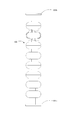
- a linear collider is being constructed as a device that collides positrons and electrons to form a big bang state (ILC project). As shown in FIG. 13, the linear collider uses a niobium hollow tube 100 having flanges 101a and 101b at both ends and the diameter periodically changing in the axial direction.
- One factor for obtaining a predetermined effect in this experiment is whether or not the inner surface of the niobium hollow tube 100 is smooth.
- the hollow tube 100 is subjected to excessive pressure and heat during molding, the structure of the inner surface thereof is unevenly distorted. If this surface state is left as it is, the electrical and magnetic characteristics are also non-uniform, and as a result, a predetermined speed cannot be given to electrons and protons. Therefore, a method of polishing the inner surface of the hollow tube to a predetermined thickness has been developed.
- a method for polishing a niobium hollow tube two types are known: a method of polishing chemically (hereinafter referred to as “chemical polishing”) and a method of polishing electrochemically (hereinafter referred to as “electrolytic polishing”). .
- a mixed solution of hydrofluoric acid, sulfuric acid, and water is used, and niobium material is immersed in the mixed solution. It is known to polish the entire surface chemically and smoothly. It is also well known to use a mixed liquid composed of hydrofluoric acid, phosphoric acid and nitric acid as a polishing liquid used for the same purpose. In any case, these methods immerse the entire hollow tube in the polishing liquid, so the operation itself is simple, but the outer surface of the originally unnecessary hollow tube is polished to promote unnecessary contamination, aging and deterioration of the liquid. In addition, there is a problem that the amount of polishing varies significantly depending on the immersion direction of the object to be polished.
- This phenomenon involves the stirring action of the polishing liquid by the generated gas, and depending on the shape of the hollow tube, the generated gas has many disadvantages such as adhering to the inner surface and deteriorating the polishing appearance.
- This method also inherently grinds the outer surface of the hollow tube that does not require polishing, which causes unnecessary dissolution loss of the hollow tube and unnecessarily consumes and contaminates the polishing liquid.
- polishing steps occur due to intermittent polishing, and in addition, it is extremely dangerous work that handles hydrofluoric acid that generates volatile gas with high volatility and sulfuric acid with high heat generation. Yes.
- the polishing liquid is fed from the blowout hole communicating with the liquid passage pipe, and continuous electrolysis is attempted in a partially immersed state. ing.
- the polishing time can be shortened, and at the same time, the niobium material does not dissolve unnecessarily, so that unnecessary contamination and consumption of the polishing liquid are suppressed.
- the invention disclosed in Japanese Patent Laid-Open No. 11-350200 is basically the same as the invention disclosed in Japanese Patent Laid-Open No. 61-23799, except that the outlet hole provided in the liquid flow pipe is opposite to the side to be polished.
- the polishing liquid is opened to the upper side so that the polishing liquid does not flow directly into the stored polishing liquid so as to achieve uniform polishing.
- the liquid passing pipe serving as the cathode is linear, and the inner surface of the hollow tube, which is the object to be polished, has an inner diameter that changes into a wave shape as described above. Therefore, the distance between each part of the inner surface of the hollow tube serving as the anode and the cathode is not uniform, and the current is concentrated in the short distance part. It will take a lot of time and the cost will increase.
- the hollow tube is kept horizontal and the polishing liquid is stored on the lower side to perform polishing. At this time, a cavity is left on the upper side of the polishing liquid, and gas generated from the polishing liquid, such as hydrogen fluoride, is temporarily accumulated in this portion, and even if polishing proceeds, The polished surface may be altered.
- the present invention provides a polishing electrode capable of uniformly polishing the inner surface of a hollow tube, suppressing a new deterioration phenomenon due to gas, and simplifying assembly and removal of the apparatus, and an electropolishing method using the same. It is intended to provide.
- the present invention employs the following configuration for an electrode for polishing a hollow tube whose inner diameter varies depending on the position.
- a storage cylinder is disposed concentrically with the electrode shaft so as to store the blade electrode in a state where each single blade is wound around the electrode shaft.
- an axial slit is provided, and with each single blade inserted through the slit, by relatively rotating the electrode shaft and the storage cylinder, A diameter adjusting means capable of expanding and contracting each single blade in the radial direction is configured.
- the electrolytic solution is filled at any point before the electrolytic treatment.
- the polishing electrode configured as described above is inserted into the hollow tube in a state where the blade electrode is housed in the housing cylinder in the initial stage. Next, the electrode shaft is rotated with respect to the storage cylinder, and the tip of each single blade is pushed out of the storage cylinder until the distance from the inner surface of the hollow tube becomes an appropriate distance for polishing. Further, a voltage / current having a polarity corresponding to the polishing is applied between the hollow tube and the blade electrode. As a result, the distance between the cavity tube and the electrode is uniform regardless of the portion of the cavity tube, and uniform polishing can be performed in a short time over the entire area of the cavity tube.
- the electrode shaft is rotated in the opposite direction to the housing cylinder, each blade of the blade electrode is housed in the housing cylinder, and the blade electrode can be pulled out from the hollow tube.
- the distance between the hollow tube and the electrode is uniform regardless of the portion of the hollow tube, and uniform polishing can be performed in a short time over the entire area of the hollow tube. Therefore, when the internal structure of the hollow tube becomes uniform and the hollow tube is used as an electron or proton accelerator, higher quality acceleration can be achieved.
- the present invention can be used for polishing a hollow tube whose inner surface shape is not uniform, and the use of the hollow tube is not limited to an accelerator. Further, the present invention can be used not only for electrolytic polishing but also for electrolytic plating.
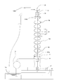
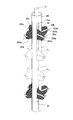
- FIG. 1 is a side view showing a use state of an electrode of the present invention.
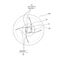
- FIG. 2 is a plan view showing a state before use of the unit electrode of the present invention.
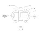
- FIG. 3 is a side view of FIG.
- FIG. 4 is a plan view showing when the unit electrode of the present invention is used.
- FIG. 5 is a side view of FIG.
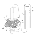
- FIG. 6 is a perspective view showing another embodiment of the electrode of the present invention.
- 7 is an exploded perspective view of FIG.
- FIG. 8 is a perspective view showing an embodiment when there are a plurality of blade electrodes.
- 9 is an exploded perspective view of FIG.
- FIG. 10 is a perspective view showing another embodiment of a single blade.
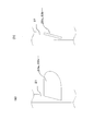
- FIG. 11 is a view when the electrode of the present invention is used sideways.
- FIG. 12 is a diagram showing an example of a single blade of a blade electrode having a screw effect.
- Fig. 13 is a front view of the hollow tube
- FIG. 1 is a diagram showing a state in which a hollow tube is electropolished using the electrode according to the present invention
- FIGS. 2 to 5 show one unit of the electrode used in the present invention (one bulge of the hollow tube).
- the unit electrode will be described.
- FIG. 2 is a plan view showing a state in which an electrode is mounted on a hollow tube and shows a state before reaching a use state
- FIG. 3 is a side view thereof
- FIG. 4 is a state in which the electrode is mounted on the hollow tube and in use
- FIG. 5 is a side view thereof.
- the electrode shaft 21 has a base end with a predetermined width in the axial direction and an outer peripheral end corresponding to the shape of the inner surface of the bulge portion of the hollow tube 100 to be polished, and at least the outer peripheral end is made of metal.
- a single blade or a plurality of thin blades 22a, 22b,... (Four in the drawing) are arranged at equal intervals in the circumferential direction to form the blade electrode 22.
- Each of the single blades 22a, 22b,... Constituting the blade electrode 22 has flexibility and has a minimum diameter when wound on the electrode shaft 21, and in this state, is concentric with the electrode shaft 21. It is accommodated in the arranged storage cylinder 29.
- a slit group 23 (23a, 23b,...) In the axial direction is provided at a position corresponding to the tip of each single blade 22a, 22b,. .. Are inserted through the slits 23a, 23b,... To such an extent that the tips of the single blades 22a, 22b,.
- the diameter can be adjusted (diameter adjusting means: electrode shaft 21 + blade electrode 22 + housing cylinder 29 + slit group 23).
- a configuration in which the storage cylinder 29 is concentrically disposed on the electrode shaft 21 for example, a configuration in which a spacer 30 having a diameter larger than that of the electrode shaft 21 and corresponding to the diameter of the storage cylinder 29 is fitted to the electrode shaft 21. Conceivable.
- the blade electrode 22 takes two modes, that is, a storage state and an operation state. That is, as shown in FIGS. 2 and 3, the state in which the tips of the single blades 22a, 22b,... Slightly protrude from the slits 23a, 23b,. 4. As shown in FIG. 5, the electrode shaft 21 and the housing cylinder 29 are relatively rotated so that the outer peripheral ends of the single blades 22a, 22b,... Are pushed close to the inner peripheral surface of the cavity tube 100 ( The distance between the outer peripheral ends of the single blades 22a, 22b,... And the inner peripheral surface of the hollow tube 100 is, for example, about 1 cm).
- FIG. 6 is a perspective view showing a more specific embodiment of the blade electrode 22 shown in FIGS. 2 to 5, and FIG. 7 is an exploded view thereof.
- At least one single blade 22a, 22b,... Having a shape corresponding to the swelling of the hollow tube 100 is attached to the electrode shaft 21 to constitute the blade electrode 22.
- the single blades 22a, 22b,... Constituting the blade electrode 22 are formed of a metal (for example, aluminum, copper) network.
- Each of the single blades 22a, 22b,... Is made of a thin metal or synthetic resin shape retaining material 221a, 221b,. 21 side) to the tip (in the radial direction) is attached by welding or welding.
- each single blade is made flexible, and the insulation and edge of the mesh surface are provided. It is good also as a structure which ensures the electroconductivity of an edge.
- the spacer 30 having a diameter larger than that of the electrode shaft 21 is fixed to the upper and lower positions of the blade electrode 22 of the electrode shaft 21. .
- the storage cylinder 29 is configured such that the diameter thereof is the same as that of the spacer 30 and the slits 23a, 23b,.
- the storage cylinder 29 configured as described above is fitted around the electrode shaft 21 via the spacer 30. At this time, the single blades 22a, 22b,. ⁇ Make sure it is plugged into Thus, the electrode 20 (electrode shaft 21 + blade electrode 22 + housing cylinder 29) is formed.
- the initial state of the electrode 20 is the storage state, and the electrode 20 is inserted into the hollow tube 100 in this state.
- the holding tube 29 is held by hand so that it does not rotate, and only the electrode shaft 21 is rotated.
- the inside of the hollow tube 100 is filled with an electrolytic solution, an electric field necessary for polishing is applied between the blade electrode 22 and the hollow tube 100, and the electrode 20 is rotated by the driving means 120 (at this time, the storage cylinder 29 is also together). Rotation), the inner surface of the cavity tube 100 is electropolished.
- the electrode tube 21 is rotated only in the opposite direction to the above-mentioned operation state by holding the storage tube 29 by hand so that the storage tube 29 does not rotate. become.
- the slits 23a, 23b,... Of the storage cylinder 29 and the single blades 22a, 22b,... Normally do not slide against each other due to frictional force. In order to form it, a force exceeding the frictional force is required.
- the electrode shaft 21 is rotated during electropolishing, the electrode shaft 21 and the storage cylinder 29 are both rotated by the frictional force.
- the auxiliary electrodes 220a, 220b,... Having a predetermined width and having a predetermined length in the circumferential direction are further provided at the tips of the single blades 22a, 22b,.
- the auxiliary electrodes 220a, 220b,... are in a state along the circumferential shape near the tip of the bulge portion on the inner peripheral surface of the cavity pipe 100 to be polished.
- the auxiliary electrodes 220a, 220b,... Can be provided on the single blade shown in FIG.
- the auxiliary electrodes 220a, 220b,... are provided at the tips, the bulge of the hollow tube 100 that normally has the least current flow when the single blades 22a, 22b,. A sufficient amount of current can be passed through the auxiliary electrodes 220a, 220b,. Further, since the auxiliary electrodes 220a, 220b,... Are longer than the gaps between the slits 23a, 23b,..., They serve as stoppers when the single blades 22a, 22b,. The tips of the single blades 22a, 22b,... Do not enter deeper than the slits 23a, 23b,.
- the unit electrode 20 is configured, but the number of bulges on the inner peripheral surface of the cavity tube 100 is not one, but there are a plurality of periodic in the axial direction as shown in FIG. Therefore, as shown in FIGS. 8 and 9, the actual electrode 20 has the length of the electrode shaft 21 corresponding to the length of the shaft of the hollow tube 100, and the number of blade electrodes 22 is the number of the inner surface of the hollow tube 100. It is provided corresponding to the number of bulges. Further, as shown in FIGS. 8 and 9, the storage tube 29 is also substantially the same length as the electrode shaft 21, and is provided with a set of slit groups 23 (23a, 23b,). Common to a plurality of single wings in the direction.
- FIG. 1 is a side view showing an apparatus for polishing the inner surface of a hollow tube using the electrode configured as described above.
- a base 11 is provided on the base 10, and a liquid introduction port 14 is provided below the center of the base 11.
- a polishing liquid from a polishing liquid tank 15 is supplied to the liquid introduction port 14 via a pump 16. Further, the polishing liquid can be introduced into the hollow tube 100 placed on the gantry 11 through the liquid introduction port 14.
- the cavity pipe 100 which is an object to be polished, is fixed to the upper side of the gantry 11 using one flange 101a.
- the accommodated electrode 20 is inserted from the upper end of the cavity tube 100.
- the electrode shaft 21 of the electrode 20 penetrates to the lower side of the liquid inlet 14 in a liquid-tight and rotatable manner, and a connector 19 with a lead is attached to the lower end thereof. Since the hollow tube 100 is vertically long, the support frame 18 that fixes the hollow tube 100 is supported by a support (not shown) in order to ensure stability on the gantry 11.
- the operator holds the storage cylinder 29 by hand, rotates the electrode shaft 21, and extends the diameters of the single blades 22a, 22b,.
- the liquid outlet 19 is fixed on the other flange 101 b of the hollow tube 100.
- the electrode shaft 21 protrudes in a liquid-tight and rotatable manner on the upper end of the liquid outlet port 19.
- the storage cylinder 29 is configured to be able to rotate with respect to the hollow tube 100 when a rotational force is applied to the electrode shaft 21, and when the electrode shaft 21 rotates, each single blade 22a, 22b. Will rotate inside. Further, the rotational force may be an offense given by the driving means 120.
- the liquid supply pump 16 introduces the polishing liquid from the liquid inlet 14 at a predetermined flow rate, fills the cavity tube 100, and discharges it from the liquid outlet 19, and the electrode shaft 21 and the cavity are formed.
- an electric field necessary for polishing is applied between the tube 100 and the electrode shaft 21 is slowly rotated, the inner surface of the hollow tube 100 is polished.
- Various conditions such as the inflow rate of the electrolytic solution and the strength of the electric field are not the gist of the present invention, so detailed description thereof is omitted here.
- the polishing liquid is discharged (for example, from a drain (not shown) provided in the liquid inlet 14), and cleaning water is sent from the liquid supply pump 16 to the cavity tube 100 for cleaning. . Thereafter, the electrode 20 is placed in the retracted state, and the work is completed by removing the electrode 20 from the hollow tube 100.
- FIG. 11 is a diagram in the case where the electrode of the present invention is used sideways.
- Rotating cavity receivers 102 a and 102 b that receive the flanges 101 a and 101 b of the hollow tube 100 in a rotatable and liquid-tight manner are provided on the mount 11 on the base 10.
- the position of one rotary cavity receiver (for example, 102a) is fixed with respect to the base 10, but the other rotary cavity receiver (for example, 102b) is mounted on the base 10 together with the base 11 of the cavity tube 100. It is configured so that it can move horizontally in the axial direction, and as described below, the cavity tube 100 can be fixed in a state of being sandwiched between the rotary cavity receivers 102a and 102b.
- the liquid inlet 14 is fixed to the outside of the one rotary cavity receiver 102a (the opposite side of the rotary cavity receiver 102b), and the inlet 141 is at a height position corresponding to the axis of the cavity pipe 100 of the liquid inlet 14. Is provided.
- the inlet 141 is configured such that the electrolytic solution can be supplied from the liquid supply pump 16 to the liquid inlet 14 via the pipe 31a.
- a liquid outlet 17 is fixed to the outside of the other rotary cavity receiver 102b, and an outlet 171 is provided at a height corresponding to the axis of the hollow pipe 100 of the liquid outlet 17 to open the pipe 31b.
- the electrolyte can be discharged to the tank 15.
- FIG. 12 The unit blades 22a, 22b,... Of the blade electrode 20 are shown in FIG. 12 with respect to the axial direction of the shaft electrode 21 (FIG. 12 (a) is a front view and FIG. 12 (b) is a side view of FIG. 12 (a)).
- FIG. 12 (a) is a front view
- FIG. 12 (b) is a side view of FIG. 12 (a)).
- the shape is slightly inclined or the tip is twisted so as to have a screw function.
- the function of transition from the storage state to the operating state is not impaired.
- the electrolytic polishing apparatus and the blade electrode are configured.
- the flange 101a of the hollow tube 100 is rotatably and liquid-tightly fixed to one rotary cavity receiver 102a (the liquid inlet 14 and the hollow tube). (With communication with 100 ensured).
- the electrode 20 is inserted from the other end of the hollow tube 100 in the housed state.
- the electrode shaft 21 penetrates the liquid introduction port 14 in a liquid-tight and rotatable manner, and the lead connector 19 is attached to the tip thereof.
- an operating state is formed by holding the storage cylinder 29 by hand and turning the electrode shaft 21 in the same manner as the vertical type.
- the other rotary cavity receiver 102b is moved and held by the other flange 101b to fix the position of the hollow pipe 100 in a rotatable and liquid-tight manner (the communication between the liquid outlet 17 and the hollow pipe 100 is In a secured state).
- the conductive rubber roller 110 is in contact with the outside of the hollow tube 100 while the hollow rubber tube 100 is held by the two rotary cavity receivers 102a and 102b, and the conductive rubber roller 110 holds the hollow tube 100 by driving the driving means 120. It is designed to rotate.
- the liquid supply pump 16 is operated to fill the electrolyte up to the vicinity of the axial position of the cavity tube 100, an electric field necessary for polishing is applied between the electrode shaft 21 and the cavity tube 100, and the driving unit 120. Then, the hollow tube 100 is rotated slowly. As a result, electrolytic polishing proceeds. At this time, due to the screw effect of the single blades 22 a, 22 b... That are inclined (or twisted) as described above, the electrolytic solution is pushed out toward the outlet port 17 as the hollow tube 100 rotates. To do. Of course, the blade electrode 20 may be positively rotated in order to enhance the effect of pushing out the electrolyte. An electric field is supplied to the hollow tube 100 through the conductive rubber roller 110.
- the electrolytic solution is discharged.
- the electrolytic solution is drawn out with the base 10 alone or the hollow tube 100 alone.
- the blade electrode 20 may be put in the retracted state, and the electrode is extracted, and the polishing operation is completed.
- a polishing liquid similar to the conventional one for example, a polishing liquid made of hydrofluoric acid, sulfuric acid, and water
- the thickness polished here is 50 ⁇ m to 100 ⁇ m when the hollow tube is a high-speed accelerator.
- the voltage applied at the time of polishing is around 15 V, and the flowing current is about 20 A / dm 2 .
- the electrode used in the present invention can be used not only for electrolytic polishing of niobium but also for electrolytic polishing of the inner surface of various metal tubes, and can also be used for electrolytic plating as well as electrolytic polishing.
- the present invention provides a hollow tube whose inner diameter varies depending on the portion, and by providing an electrode configured to expand a blade electrode having a single blade matched to the inner diameter, the inner surface can be shortened for a short time. Can be uniformly polished. It can be applied to products that require higher accuracy, such as high-speed accelerators. Of course, it can be applied not only to electropolishing but also to electroplating. In this respect as well, a more precise product finish can be expected, and industrial applicability is extremely high.
Landscapes
- Chemical & Material Sciences (AREA)
- Engineering & Computer Science (AREA)
- Chemical Kinetics & Catalysis (AREA)
- Electrochemistry (AREA)
- Materials Engineering (AREA)
- Metallurgy (AREA)
- Organic Chemistry (AREA)
- Electrical Discharge Machining, Electrochemical Machining, And Combined Machining (AREA)
Description
11 架台
14 液導入口
17 液導出口
21 電極軸
20 電極
21 電極軸
22 翼電極
22a、22b・・ 単翼
23 スリット群
23a、23b・・ スリット
29 収納筒
100 空洞管
Claims (3)
- 電極軸と、
前記電極軸の軸方向に所定幅で先端が、空洞管の内周面形状に対応する単翼を少なくとも1枚、周方向に等間隔に配置した翼電極と、
前記各単翼が電極軸に巻回された状態で、翼電極を収納する電極軸と同心に配置された収納筒と、
前記収納筒の各単翼に対応する位置に、軸方向のスリットを設け、当該スリットに各単翼を挿通した状態で、電極軸と収納筒とを相対的に回転することによって、各単翼を径方向に拡縮可能な径調整手段と、
を備えた、空洞管の研磨用電極。 - 第1項記載の空洞管の研磨用電極を最初の段階で、収納筒に翼電極を収納した状態として、空洞管に挿入するステップ、
収納筒に対して電極軸を回転させて、各単翼の先端が空洞管の内周面と、研磨を行うに適切な距離になるまで収納筒から押し出すステップ、
前記空洞管と翼電極の間に研磨に応じた極性の電圧・電流を印加するステップ、
を備えた空洞管の電解研磨方法。 - 更に、研磨を終了した後に、収納筒に対して電極軸を前記とは逆に回転させて、翼電極の各単翼を収納筒に収納するステップ
翼電極を研磨対象の空洞管から引き抜くステップ
を備えた請求項2に記載の空洞管の電解研磨方法。
Priority Applications (3)
| Application Number | Priority Date | Filing Date | Title |
|---|---|---|---|
| EP13816291.2A EP2873754B1 (en) | 2012-07-11 | 2013-07-08 | Electrode for polishing hollow tube, and electrolytic polishing method using same |
| JP2014524789A JP5807938B2 (ja) | 2012-07-11 | 2013-07-08 | 空洞管の研磨用電極とそれを用いた電解研磨方法 |
| US14/413,520 US9689086B2 (en) | 2012-07-11 | 2013-07-08 | Electrode for polishing hollow tube, and electrolytic polishing method using same |
Applications Claiming Priority (2)
| Application Number | Priority Date | Filing Date | Title |
|---|---|---|---|
| JP2012-155490 | 2012-07-11 | ||
| JP2012155490 | 2012-07-11 |
Publications (1)
| Publication Number | Publication Date |
|---|---|
| WO2014010540A1 true WO2014010540A1 (ja) | 2014-01-16 |
Family
ID=49915994
Family Applications (1)
| Application Number | Title | Priority Date | Filing Date |
|---|---|---|---|
| PCT/JP2013/068593 Ceased WO2014010540A1 (ja) | 2012-07-11 | 2013-07-08 | 空洞管の研磨用電極とそれを用いた電解研磨方法 |
Country Status (4)
| Country | Link |
|---|---|
| US (1) | US9689086B2 (ja) |
| EP (1) | EP2873754B1 (ja) |
| JP (1) | JP5807938B2 (ja) |
| WO (1) | WO2014010540A1 (ja) |
Cited By (5)
| Publication number | Priority date | Publication date | Assignee | Title |
|---|---|---|---|---|
| JP2016030859A (ja) * | 2014-07-30 | 2016-03-07 | マルイ鍍金工業株式会社 | 空洞管の研磨装置 |
| WO2016056620A1 (ja) * | 2014-10-10 | 2016-04-14 | マルイ鍍金工業株式会社 | 空洞管の研磨用ロータ |
| JP2020055723A (ja) * | 2018-10-04 | 2020-04-09 | 株式会社Nsc | 黒鉛精製装置 |
| KR20230125735A (ko) * | 2022-02-21 | 2023-08-29 | 인하대학교 산학협력단 | 파이프 내부 전해연마용 가변 전극 |
| WO2025248263A1 (en) * | 2024-05-31 | 2025-12-04 | Holdson Limited | System and electrode apparatus for electrochemical polishing of channels |
Families Citing this family (6)
| Publication number | Priority date | Publication date | Assignee | Title |
|---|---|---|---|---|
| US9006147B2 (en) | 2012-07-11 | 2015-04-14 | Faraday Technology, Inc. | Electrochemical system and method for electropolishing superconductive radio frequency cavities |
| US11021807B2 (en) | 2018-02-02 | 2021-06-01 | Marui Galvanizing Co., Ltd. | Electrolytic polishing method and device |
| DE102018128345A1 (de) * | 2018-11-13 | 2020-05-14 | Biotronik Ag | Elektrodenstift |
| JP7036778B2 (ja) * | 2019-09-25 | 2022-03-15 | トーステ株式会社 | 金属管内面電解研磨方法、金属管内面電解研磨装置および金属管内面電解研磨装置の使用方法 |
| CN114855258B (zh) * | 2022-05-13 | 2024-02-02 | 中国科学院近代物理研究所 | 用于椭球型超导腔电化学抛光的电极及其安装方法 |
| CN116896479B (zh) * | 2023-08-29 | 2025-07-25 | 北京火山引擎科技有限公司 | 域名检测方法、设备及存储介质 |
Citations (9)
| Publication number | Priority date | Publication date | Assignee | Title |
|---|---|---|---|---|
| JPS5171822U (ja) * | 1974-12-03 | 1976-06-07 | ||
| JPS5512116B2 (ja) | 1971-09-18 | 1980-03-29 | ||
| JPS57114669A (en) | 1980-08-29 | 1982-07-16 | Siemens Ag | Chemical grinding of niobium member |
| JPS6123799A (ja) | 1984-07-10 | 1986-02-01 | Mitsubishi Heavy Ind Ltd | ニオブ中空体の電解研摩方法 |
| JPS6291900A (ja) * | 1985-10-17 | 1987-04-27 | 日揮株式会社 | 電解泡除染装置 |
| JPH0398990U (ja) * | 1989-12-26 | 1991-10-15 | ||
| JPH11350200A (ja) | 1998-06-09 | 1999-12-21 | Nomura Mekki:Kk | 金属製中空体の内面研磨方法及び研磨装置 |
| JP2007276062A (ja) * | 2006-04-07 | 2007-10-25 | Denso Corp | 電解加工方法および電解加工装置 |
| JP2011086450A (ja) * | 2009-10-14 | 2011-04-28 | Mitsubishi Heavy Ind Ltd | 超伝導加速空洞の表面処理方法 |
Family Cites Families (11)
| Publication number | Priority date | Publication date | Assignee | Title |
|---|---|---|---|---|
| JPS4946227B1 (ja) * | 1970-05-09 | 1974-12-09 | ||
| JPS5717574B2 (ja) | 1972-09-09 | 1982-04-12 | ||
| JPS5171822A (en) | 1974-12-16 | 1976-06-22 | Acme Cleveland Corp | Nakago mataha igatano isosochi |
| JPS5512116A (en) | 1978-07-11 | 1980-01-28 | Nippon Oil Co Ltd | Plugging composition |
| EP0046913B1 (de) | 1980-08-29 | 1984-12-05 | Siemens Aktiengesellschaft | Verfahren zum chemischen Polieren von Niob-Teilen, insbesondere eines Hohlraumresonators |
| JPH0398990A (ja) | 1989-09-13 | 1991-04-24 | Toshiba Corp | マンコンベアの安全装置 |
| JPH10296542A (ja) | 1997-04-28 | 1998-11-10 | Shinko Tokushu Kokan Kk | 長尺金属管内面の電解複合研磨方法及びその装置 |
| US6217726B1 (en) | 1997-05-22 | 2001-04-17 | Therma Corporation, Inc. | Tube inner surface electropolishing device with electrolyte dam |
| US7077721B2 (en) | 2000-02-17 | 2006-07-18 | Applied Materials, Inc. | Pad assembly for electrochemical mechanical processing |
| TW572063U (en) | 2001-11-28 | 2004-01-11 | Ind Tech Res Inst | An electropolishing process means for an inner surface of a long tube |
| CN101636528B (zh) * | 2007-03-26 | 2011-06-29 | 株式会社大和卓越 | 内表面电镀用绝缘隔离体及辅助阳极单元 |
-
2013
- 2013-07-08 JP JP2014524789A patent/JP5807938B2/ja active Active
- 2013-07-08 EP EP13816291.2A patent/EP2873754B1/en active Active
- 2013-07-08 US US14/413,520 patent/US9689086B2/en active Active
- 2013-07-08 WO PCT/JP2013/068593 patent/WO2014010540A1/ja not_active Ceased
Patent Citations (9)
| Publication number | Priority date | Publication date | Assignee | Title |
|---|---|---|---|---|
| JPS5512116B2 (ja) | 1971-09-18 | 1980-03-29 | ||
| JPS5171822U (ja) * | 1974-12-03 | 1976-06-07 | ||
| JPS57114669A (en) | 1980-08-29 | 1982-07-16 | Siemens Ag | Chemical grinding of niobium member |
| JPS6123799A (ja) | 1984-07-10 | 1986-02-01 | Mitsubishi Heavy Ind Ltd | ニオブ中空体の電解研摩方法 |
| JPS6291900A (ja) * | 1985-10-17 | 1987-04-27 | 日揮株式会社 | 電解泡除染装置 |
| JPH0398990U (ja) * | 1989-12-26 | 1991-10-15 | ||
| JPH11350200A (ja) | 1998-06-09 | 1999-12-21 | Nomura Mekki:Kk | 金属製中空体の内面研磨方法及び研磨装置 |
| JP2007276062A (ja) * | 2006-04-07 | 2007-10-25 | Denso Corp | 電解加工方法および電解加工装置 |
| JP2011086450A (ja) * | 2009-10-14 | 2011-04-28 | Mitsubishi Heavy Ind Ltd | 超伝導加速空洞の表面処理方法 |
Non-Patent Citations (1)
| Title |
|---|
| See also references of EP2873754A4 * |
Cited By (9)
| Publication number | Priority date | Publication date | Assignee | Title |
|---|---|---|---|---|
| JP2016030859A (ja) * | 2014-07-30 | 2016-03-07 | マルイ鍍金工業株式会社 | 空洞管の研磨装置 |
| WO2016056620A1 (ja) * | 2014-10-10 | 2016-04-14 | マルイ鍍金工業株式会社 | 空洞管の研磨用ロータ |
| JPWO2016056620A1 (ja) * | 2014-10-10 | 2017-07-20 | マルイ鍍金工業株式会社 | 空洞管の研磨用ロータ |
| US10246792B2 (en) | 2014-10-10 | 2019-04-02 | Marui Galvanizing Co., Ltd. | Rotor for polishing hollow tubes |
| JP2020055723A (ja) * | 2018-10-04 | 2020-04-09 | 株式会社Nsc | 黒鉛精製装置 |
| JP7160271B2 (ja) | 2018-10-04 | 2022-10-25 | 株式会社Nsc | 黒鉛精製装置 |
| KR20230125735A (ko) * | 2022-02-21 | 2023-08-29 | 인하대학교 산학협력단 | 파이프 내부 전해연마용 가변 전극 |
| KR102848064B1 (ko) * | 2022-02-21 | 2025-08-20 | 인하대학교 산학협력단 | 파이프 내부 전해연마용 가변 전극 |
| WO2025248263A1 (en) * | 2024-05-31 | 2025-12-04 | Holdson Limited | System and electrode apparatus for electrochemical polishing of channels |
Also Published As
| Publication number | Publication date |
|---|---|
| US20150159294A1 (en) | 2015-06-11 |
| JP5807938B2 (ja) | 2015-11-10 |
| US9689086B2 (en) | 2017-06-27 |
| EP2873754A4 (en) | 2015-08-19 |
| JPWO2014010540A1 (ja) | 2016-06-23 |
| EP2873754B1 (en) | 2016-09-14 |
| EP2873754A1 (en) | 2015-05-20 |
Similar Documents
| Publication | Publication Date | Title |
|---|---|---|
| JP5807938B2 (ja) | 空洞管の研磨用電極とそれを用いた電解研磨方法 | |
| EP2882265A1 (en) | Superconducting accelerating cavity and electropolishing method for superconducting accelerating cavity | |
| US9617651B2 (en) | Anodizing apparatus and anodizing method | |
| US20200199771A1 (en) | Electrolytic polishing method and device | |
| WO2016056620A1 (ja) | 空洞管の研磨用ロータ | |
| KR101510042B1 (ko) | 회전형 금속봉 전해연마 장치 | |
| US20150184308A1 (en) | Device for electrochemical treatment, locally in particular, of a conductor substrate | |
| JP2008202135A (ja) | 中空部材の製造方法及び陽極酸化処理用治具 | |
| JP6374724B2 (ja) | 空洞管の研磨装置 | |
| JP6231838B2 (ja) | 空洞管の部分電解研磨治具と電解研磨方法 | |
| JP5219753B2 (ja) | 細管内壁のめっき方法 | |
| JP6231835B2 (ja) | 空洞管の電解研磨装置 | |
| CN202047159U (zh) | 处理槽以及电解处理装置 | |
| CN114990687B (zh) | 一种电化学抛光装置及其使用方法、经导管介入泵的工件 | |
| CN216738622U (zh) | 电化学抛光装置 | |
| JP7437016B2 (ja) | 電解研磨方法および装置 | |
| JP3729013B2 (ja) | アルミ電解コンデンサ用電極箔の製造方法 | |
| JP6804086B2 (ja) | 電解処理装置および方法 | |
| CN102758241A (zh) | 去除金属或金属复合材料线材的外层的装置、系统及方法 | |
| KR101198412B1 (ko) | 기판도금장치 및 기판도금방법 | |
| JP2018127669A (ja) | バレルめっき装置 | |
| CN118461115B (zh) | 异形结构筒体内壁电解抛光设备及电解抛光方法 | |
| CN207244037U (zh) | 一种电镀设备 | |
| JP2005232531A (ja) | 電鋳による多心金属管の製造方法 | |
| TWI603799B (zh) | Electrochemical processing equipment and processing methods |
Legal Events
| Date | Code | Title | Description |
|---|---|---|---|
| 121 | Ep: the epo has been informed by wipo that ep was designated in this application |
Ref document number: 13816291 Country of ref document: EP Kind code of ref document: A1 |
|
| ENP | Entry into the national phase |
Ref document number: 2014524789 Country of ref document: JP Kind code of ref document: A |
|
| WWE | Wipo information: entry into national phase |
Ref document number: 14413520 Country of ref document: US |
|
| NENP | Non-entry into the national phase |
Ref country code: DE |
|
| REEP | Request for entry into the european phase |
Ref document number: 2013816291 Country of ref document: EP |
|
| WWE | Wipo information: entry into national phase |
Ref document number: 2013816291 Country of ref document: EP |