WO2014010557A1 - バスバモジュール - Google Patents
バスバモジュール Download PDFInfo
- Publication number
- WO2014010557A1 WO2014010557A1 PCT/JP2013/068647 JP2013068647W WO2014010557A1 WO 2014010557 A1 WO2014010557 A1 WO 2014010557A1 JP 2013068647 W JP2013068647 W JP 2013068647W WO 2014010557 A1 WO2014010557 A1 WO 2014010557A1
- Authority
- WO
- WIPO (PCT)
- Prior art keywords
- output terminal
- main body
- module
- cover
- terminal installation
- Prior art date
- Legal status (The legal status is an assumption and is not a legal conclusion. Google has not performed a legal analysis and makes no representation as to the accuracy of the status listed.)
- Ceased
Links
Images


Classifications
-
- H—ELECTRICITY
- H01—ELECTRIC ELEMENTS
- H01R—ELECTRICALLY-CONDUCTIVE CONNECTIONS; STRUCTURAL ASSOCIATIONS OF A PLURALITY OF MUTUALLY-INSULATED ELECTRICAL CONNECTING ELEMENTS; COUPLING DEVICES; CURRENT COLLECTORS
- H01R13/00—Details of coupling devices of the kinds covered by groups H01R12/70 or H01R24/00 - H01R33/00
- H01R13/44—Means for preventing access to live contacts
- H01R13/447—Shutter or cover plate
-
- H—ELECTRICITY
- H01—ELECTRIC ELEMENTS
- H01M—PROCESSES OR MEANS, e.g. BATTERIES, FOR THE DIRECT CONVERSION OF CHEMICAL ENERGY INTO ELECTRICAL ENERGY
- H01M50/00—Constructional details or processes of manufacture of the non-active parts of electrochemical cells other than fuel cells, e.g. hybrid cells
- H01M50/20—Mountings; Secondary casings or frames; Racks, modules or packs; Suspension devices; Shock absorbers; Transport or carrying devices; Holders
- H01M50/271—Lids or covers for the racks or secondary casings
-
- H—ELECTRICITY
- H01—ELECTRIC ELEMENTS
- H01M—PROCESSES OR MEANS, e.g. BATTERIES, FOR THE DIRECT CONVERSION OF CHEMICAL ENERGY INTO ELECTRICAL ENERGY
- H01M50/00—Constructional details or processes of manufacture of the non-active parts of electrochemical cells other than fuel cells, e.g. hybrid cells
- H01M50/50—Current conducting connections for cells or batteries
- H01M50/502—Interconnectors for connecting terminals of adjacent batteries; Interconnectors for connecting cells outside a battery casing
- H01M50/503—Interconnectors for connecting terminals of adjacent batteries; Interconnectors for connecting cells outside a battery casing characterised by the shape of the interconnectors
-
- H—ELECTRICITY
- H01—ELECTRIC ELEMENTS
- H01M—PROCESSES OR MEANS, e.g. BATTERIES, FOR THE DIRECT CONVERSION OF CHEMICAL ENERGY INTO ELECTRICAL ENERGY
- H01M50/00—Constructional details or processes of manufacture of the non-active parts of electrochemical cells other than fuel cells, e.g. hybrid cells
- H01M50/50—Current conducting connections for cells or batteries
- H01M50/502—Interconnectors for connecting terminals of adjacent batteries; Interconnectors for connecting cells outside a battery casing
- H01M50/509—Interconnectors for connecting terminals of adjacent batteries; Interconnectors for connecting cells outside a battery casing characterised by the type of connection, e.g. mixed connections
- H01M50/51—Connection only in series
-
- H—ELECTRICITY
- H01—ELECTRIC ELEMENTS
- H01M—PROCESSES OR MEANS, e.g. BATTERIES, FOR THE DIRECT CONVERSION OF CHEMICAL ENERGY INTO ELECTRICAL ENERGY
- H01M50/00—Constructional details or processes of manufacture of the non-active parts of electrochemical cells other than fuel cells, e.g. hybrid cells
- H01M50/50—Current conducting connections for cells or batteries
- H01M50/502—Interconnectors for connecting terminals of adjacent batteries; Interconnectors for connecting cells outside a battery casing
- H01M50/514—Methods for interconnecting adjacent batteries or cells
- H01M50/517—Methods for interconnecting adjacent batteries or cells by fixing means, e.g. screws, rivets or bolts
-
- H—ELECTRICITY
- H01—ELECTRIC ELEMENTS
- H01M—PROCESSES OR MEANS, e.g. BATTERIES, FOR THE DIRECT CONVERSION OF CHEMICAL ENERGY INTO ELECTRICAL ENERGY
- H01M50/00—Constructional details or processes of manufacture of the non-active parts of electrochemical cells other than fuel cells, e.g. hybrid cells
- H01M50/20—Mountings; Secondary casings or frames; Racks, modules or packs; Suspension devices; Shock absorbers; Transport or carrying devices; Holders
- H01M50/204—Racks, modules or packs for multiple batteries or multiple cells
-
- Y—GENERAL TAGGING OF NEW TECHNOLOGICAL DEVELOPMENTS; GENERAL TAGGING OF CROSS-SECTIONAL TECHNOLOGIES SPANNING OVER SEVERAL SECTIONS OF THE IPC; TECHNICAL SUBJECTS COVERED BY FORMER USPC CROSS-REFERENCE ART COLLECTIONS [XRACs] AND DIGESTS
- Y02—TECHNOLOGIES OR APPLICATIONS FOR MITIGATION OR ADAPTATION AGAINST CLIMATE CHANGE
- Y02E—REDUCTION OF GREENHOUSE GAS [GHG] EMISSIONS, RELATED TO ENERGY GENERATION, TRANSMISSION OR DISTRIBUTION
- Y02E60/00—Enabling technologies; Technologies with a potential or indirect contribution to GHG emissions mitigation
- Y02E60/10—Energy storage using batteries
Definitions
- the present invention relates to a bus bar module, and more particularly, to a bus bar module installed and used in a battery assembly.
- a bus bar module 307 that includes a resin case 301 and a cover 303 and is used by being installed in a battery assembly 305 is known (see Patent Document 1).
- the cover 303 of the bus bar module 307 is provided with a door part (opening / closing part) 311 via a hinge part 309.
- the door portion 311 is provided with a locking hole 313.
- the resin case 301 is provided with locking claws 315.
- the door 311 rotates with the hinge 309 as a fulcrum.
- the electrode 317 is covered with the door portion 311.
- the electrode 317 is exposed.
- the door portion 311 By opening the door portion 311, the work of connecting an electric wire from an external device to the electrode 317 and the maintenance work of the battery assembly 305 are facilitated. Further, by closing the door portion 311, the electrode 317 is covered and adhesion of dust or the like to the electrode 317 is prevented.
- the locking claw 315 engages with the locking hole 313 of the door part 311. By this engagement, the door portion 311 is fixed, and the door portion 311 can be kept closed.
- Patent Document 2 can be listed as a document related to the conventional technology.
- the rigidity of the resin case 301 on the receiving side tends to be low when the door portion 311 is closed, and the force received from the door portion 311 when the locking claw 315 enters the locking hole 313. Therefore, there is a problem that the resin case 301 (a portion in the vicinity of the locking claw 315) is bent, and it becomes difficult to align and engage the locking claw 315 with the locking hole 313. In other words, the resin case 301 (a portion in the vicinity of the locking claw 315) bends to cause a displacement of the locking hole 313 with respect to the locking claw 315, and the locking claw (locking portion) 315 is locked. There is a problem that it is difficult to enter the hole (locked portion) 313 and it is difficult to fix the door portion 311 in the closed position.
- the present invention has been made in view of the above problems, and in a bus bar module installed in the battery assembly in order to connect each battery of the battery assembly in series, even if the rigidity of the module body is low, It is an object of the present invention to provide a bus bar module in which a locked portion of a hinge cover is easily engaged with a locking portion of a module main body.
- a first aspect of the present invention is a bus bar module that is installed and used in the battery assembly in order to connect the batteries of the battery assembly in series.
- the bus bar module includes: a first module main body provided with an output terminal installation portion on which an output terminal is installed; a second module main body that is detachable from the first module main body; An output terminal cover provided in the first module main body through a hinge part to cover an output terminal installed in the output terminal installation part, and a cover engagement provided in the output terminal cover And a cover locked portion of the output terminal cover when the output terminal cover covers the output terminal installed in the output terminal installation portion.
- the output terminal installation part may be formed in a plate shape.
- the reinforcing portion may be formed in a plate shape.
- the reinforcing section may be configured to overlap the output terminal installation section.
- Direction of reaction force received by the output terminal installation portion from the output terminal cover when the cover locked portion is locked to the cover locking portion, and the thickness of the output terminal installation portion and the reinforcing portion The direction and the direction from the output terminal installation portion toward the reinforcement portion may be configured to coincide with each other.
- the output terminal installation part may include a flat output terminal installation part main body part and output terminal installation part ribs protruding from the output terminal installation part main body part.
- the reinforcing portion may include a flat reinforcing portion main body portion and reinforcing portion ribs protruding from the reinforcing portion main body portion.
- the extending direction of at least some of the output terminal installation ribs and the extending direction of at least some of the reinforcing ribs may intersect each other.
- at least a part of at least some of the output terminal installation ribs and at least one of the reinforcement ribs You may be comprised so that the one part site
- the locked portion of the hinge cover is fixed to the module body even if the rigidity of the module body is low.
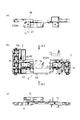
- FIG. 3 is a diagram showing a schematic configuration of a bus bar module according to an embodiment of the present invention, in which a first module main body and a second module main body are combined with each other and an output terminal cover is opened.
- B is a front view
- (a) is a IIA arrow view in (b)
- (c) is a IIC arrow view in (b). It is a perspective view of what is shown in FIG.
- FIG. 4 is a diagram showing a schematic configuration of a bus bar module according to an embodiment of the present invention, in which a first module main body and a second module main body are combined with each other and an output terminal cover is closed.
- (A) is a front view
- (b) is a VB arrow view in (a).
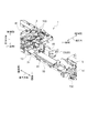
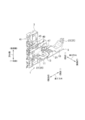
- It is a perspective view of what is shown in FIG. It is a perspective view from another viewpoint of what is shown in FIG. It is a perspective view from another viewpoint of what is shown in FIG. It is a perspective view which shows schematic structure of the bus bar module which concerns on embodiment of this invention, and the 1st module main-body part and the 2nd module main-body part have left
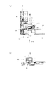
- FIG. (A) It is a perspective view from another viewpoint of what is shown in FIG. (A) is the figure which showed typically the XI part in FIG.5 (b), Comprising: It is the figure which showed what was seen by the XI arrow in FIG. 8, (b) is (a) (C) is a figure which shows only the terminal installation part which removed the reinforcement part from (a), (d) is only the reinforcement part which removed the terminal installation part from (a).
- FIG. (A) is a figure which shows the XII-XII cross section in Fig.11 (a)
- (b) is a figure which shows the comparative example with (a).
- a bus bar module (battery connector) 1 is connected to a battery assembly (not shown in FIGS. 1 to 12) in series, as in the conventional case. For example, it is installed on the side of the body.
- one direction in the bus bar module 1 is a longitudinal direction (X-axis direction), one direction orthogonal to the longitudinal direction is a longitudinal direction (Y-axis direction), and the longitudinal direction and the longitudinal direction.
- a direction perpendicular to the thickness direction is defined as a thickness direction (Z-axis direction).
- the battery is formed in, for example, an elongated rectangular parallelepiped shape, and a plus terminal and a minus terminal protrude from one surface in the longitudinal direction.
- the battery assembly is composed of a plurality of batteries (cells) formed in the same shape.
- the longitudinal directions of the respective batteries are in one horizontal direction (thickness direction in the bus bar module) and coincide with each other.
- one surface in the longitudinal direction of each battery (the surface from which the plus terminal and the minus terminal protrude) is located in one plane, and the other surface in the longitudinal direction of each battery is the other.
- the batteries are in contact with each other or spaced apart from each other in one other horizontal direction (longitudinal direction in the bus bar module) orthogonal to the one horizontal direction.
- the batteries that are aligned in the other horizontal direction in the vertical direction (vertical direction in the bus bar module 1) are in contact with each other or overlap in multiple stages such as two stages with a slight gap therebetween. Yes.
- the bus bar module 1 includes a first module main body 3 and a second module main body 5.
- a plurality of metal, flat-shaped bus bars 9 are fitted into the bus bar installation section 7 of the bus bar module 1 so as to be integrally installed.
- Each bus bar (installed bus bar) 9 installed in the bus bar module 1 is connected to each terminal of each battery when the bus bar module 1 is installed in the battery assembly, and each battery in the battery assembly is connected in series. Connected.
- the first module body 3 is made of, for example, an insulating synthetic resin and is generated by injection molding.
- the first module body 3 is provided with an output terminal installation part (output terminal support part) 13 in which the output terminal 11 is installed.
- the first module body part 3 is provided with a first module body part locking part 15.
- the output terminal 11 is integrally installed in the first module main body 3 by being fitted into the first module main body 3 (output terminal installation portion 13).
- the output terminal 11 is made of a conductive metal material, and when the bus bar module 1 is installed in the battery assembly, for example, the terminal of the battery at the end of each battery connected in series with each bus bar 9. Engage with (electrode) to conduct.
- the second module main body 5 is also made of an insulating synthetic resin in the same manner as the first module main body, and is generated by injection molding separate from the first module main body.
- the second module main body 5 is detachable with respect to the first module main body 3 and is integrated with the first module main body 3 when installed on the first module main body 3. It is like that.
- the first module main body 3 and the second module main body 5 are divided into large molds used for forming the first module main body 3 and the second module main body 5. This is to prevent the change.
- the bus bar module 1 is divided into a plurality of module main body portions 3 and 5 to be unitized, it is possible to flexibly cope with an increase in the number of batteries connected in series.
- the second module main body 5 is provided with a second module main body locking portion 17 in addition to the bus bar installation portion 7.
- the second module main body portion 5 is installed in the first module main body portion 3 by engaging the first module main body portion locking portion 15 and the second module main body portion locking portion 17 with each other.
- the first module main body 3 and the second module main body 5 are integrated, and the bus bar module 1 is generated by installing the bus bar 9, the output terminal 11 and the like in the integrated one. It has become.
- the bus bar module 1 is provided with an output terminal cover (hinge cover) 19.
- the output terminal cover 19 is for covering the output terminal 11 installed in the output terminal installation part 13, and is provided via a hinge part (for example, a hinge part composed of a self-hinge thinner than other parts) 21. 1 of the module main body 3.
- the output terminal cover 19 is integrally formed with the first module body 3 together with the hinge 21.
- the output terminal cover 19 is provided with a cover locked portion 23.
- the cover locked portion 23 is located away from the hinge portion 21 (for example, on the side opposite to the hinge portion 21).
- the output terminal cover 19 is formed in a bowl shape.
- a hinge portion 21 is provided in the vicinity of one side of the rectangular opening of the output terminal cover 19 formed in a bowl shape.
- the linear hinge portion 21 is located at a predetermined distance from the output terminal installation portion 13 of the first module main body portion 3. Then, the output terminal cover 19 is rotated by, for example, 180 ° around the hinge portion 21 as a rotation center, so that the output terminal cover 19 is installed on the output terminal installation portion 13 of the first module body 3 (an installed output terminal). ) Between the position that covers 11 (covered position; see FIG. 7 etc.) and the position where the installed output terminal 11 is opened so that the installed output terminal 11 is exposed (open position; see FIG. 4 etc.) It is designed to rotate.
- the cover locked portion 23 of the output terminal cover 19 is opposed to the side where the hinge portion 21 is provided (one side of the rectangular opening of the output terminal cover 19 formed in a bowl shape). It is provided at one side.
- the cover locked portion 23 is configured by a through-hole 25 (a through-hole penetrating a side portion of the output terminal cover 19 formed in a bowl shape) 25 provided near one other side. Yes.
- a cover locking portion 27 is provided in the output terminal installation portion 13 of the first module main body portion 3.
- the cover locking portion 27 is for locking the cover locked portion 23 of the output terminal cover 19 when the output terminal cover 19 covers the installed output terminal 11.
- the cover locked portion 23 of the output terminal cover 19 is locked to the cover locking portion 27 of the first module main body 3, and the output terminal cover 19 is covered. It is designed to be fixed in a hidden position. More specifically, for example, the cover locking portion 27 of the first module main body 3 is provided with the output terminal installation portion 13 of the first module main body 3 (the hinge portion 21 is provided at the center of the output terminal installation portion 13). It is composed of protrusions 29 formed on the opposite side).
- the second module main body 5 is provided with a reinforcing portion (output terminal installation portion reinforcing portion) 31.
- the reinforcing portion 31 is engaged with the output terminal installation portion 13 when the second module main body portion 5 is installed on the first module main body portion 3, and the cover locked portion 23 is locked with the cover locking portion 27. When this is done, deformation of the output terminal installation part 13 is prevented. That is, the second module main body 5 is installed in the first module main body 3 and the output terminal installation unit 13 is supported by the reinforcing terminal 31 engaged with the output terminal installation unit 13 to thereby support the output terminal installation unit 13. Is difficult to deform.
- the output terminal cover 19 When the cover locked portion 23 of the output terminal cover 19 is locked to the cover locking portion 27 of the first module main body 3 so as to position the output terminal cover 19 from the open position to the cover position, the output is performed.
- the reaction force received from the terminal cover 19 substantially prevents the output terminal installation portion 13 from being elastically deformed (even if elastic, the amount is very small and acceptable).
- the displacement of the cover locking portion 27 of the output terminal installation portion 13 with respect to the cover locked portion 23 of the output terminal cover 19 is substantially eliminated (the amount of displacement is within an allowable value), and the cover locked portion 23 is removed. It is possible to avoid the occurrence of a situation in which the cover engaging portion 27 and the cover engaging portion 27 do not engage with each other or become difficult.
- the output terminal installation portion 13 is formed in a plate shape (for example, a flat plate shape), and the reinforcing portion 31 is also formed in a plate shape (for example, a flat plate shape). And when the 2nd module main-body part 5 is installed in the 1st module main-body part 3, it is comprised so that the reinforcement part 31 may overlap with the output terminal installation part 13.
- FIG. 1 a plate shape
- FIG. 1 a flat plate shape
- the output terminal 11 is installed on the output terminal installation part 13 on the side opposite to the side where the reinforcing part 31 overlaps, and the output terminal cover 19 has been installed on the side opposite to the side where the reinforcing part 31 overlaps. The output terminal 11 is covered.
- the thickness direction and the direction from the output terminal installation portion 13 toward the reinforcement portion 31 are configured to coincide with each other. Yes. Note that that these directions coincide with each other means that these directions substantially coincide with each other, and includes a range that can be regarded as coincidence from the embodiment.
- the output terminal installation part 13 includes a flat output terminal installation part main body 33 and output terminal installation part ribs 35 protruding from the output terminal installation part main body 33.
- the reinforcing portion 31 includes a flat reinforcing portion main body portion 37 and reinforcing portion ribs 39 protruding from the reinforcing portion main body portion 37.
- the output terminal installation portion rib 37 protrudes from the output terminal installation portion main body 33 toward the reinforcing portion 31 and is reinforced.
- the part rib 39 protrudes from the reinforcement part main body part 37 to the output terminal installation part 13 side, and the planar tip of the output terminal installation part rib 35 and the planar tip of the reinforcement part rib 39 are in contact with each other. .
- the output terminal installation portion rib 35 and the reinforcement portion rib 39 exist between the plate-like output terminal installation portion main body portion 33 and the plate-like reinforcement portion main body portion 37.
- the extending direction of at least some of the output terminal installation portion ribs 35 and the extending direction of at least some of the reinforcing portion ribs 39 intersect each other (for example, orthogonally).
- the 2nd module main-body part 5 is installed in the 1st module main-body part 3, the one part site
- the extending direction of a part of the output terminal installation portion ribs 35 ⁇ / b> A is the thickness direction of the bus bar module 1
- the extending direction of some ribs 39 ⁇ / b> A is the longitudinal direction of the bus bar module 1.
- the bus bar module 1 will be further described.
- the first module body 3 includes a substrate-like portion 41 that is formed in a generally flat plate shape.
- a plurality of bus bar installation portions 7 are formed in the substrate-like part 41.
- the first module main body locking portion 15 is provided at one end of the substrate-like portion 41 in the longitudinal direction and is provided at one end of the substrate-like portion 41 in the longitudinal direction. Yes.
- the first module main body locking portion 15 is composed of a pair of locking claws 43 protruding from one end of the substrate-like portion 41 in the longitudinal direction and two concave portions (not shown). One of the two recesses is provided between the pair of locking claws 43.
- the output terminal installation portion 13 is provided at one end portion of the substrate-like portion 41 in the longitudinal direction, and is an intermediate portion of the substrate-like portion 41 in the longitudinal direction and two concave portions of the first module body portion locking portion 15. Is provided at the other concave portion. Moreover, the output terminal installation part 13 formed in plate shape protrudes from the substrate-shaped part 41 to the other end side in the thickness direction. The thickness direction of the plate-like output terminal installation portion 13 is the vertical direction. The output terminal installation part rib 35 protrudes from the output terminal installation part main body part 37 to one end in the longitudinal direction.
- the hinge part 21 is provided at one end of the output terminal installation part 13 in the longitudinal direction.
- a bend line (rotation center line) of the output terminal cover 19 at the hinge portion 21 extends in the thickness direction of the bus bar module 1.
- the output terminal cover 19 in the open position protrudes from one end of the hinge portion 21 in the longitudinal direction of the bus bar module 1 and opens to the other end in the vertical direction.
- the cover locking portion 27 is provided at the other end of the output terminal installation portion 13 in the longitudinal direction of the bus bar module 1.
- the cover locked portion 23 is provided in the vicinity of one end of the output terminal cover 19 in the longitudinal direction of the bus bar module 1.
- the output terminal 11 includes a flat plate-like first portion 45 and a flat plate-like second portion 47 by being formed in an “L” shape obtained by bending a flat plate-like material 90 ° at one place. Configured.
- a male screw 49 protrudes from the second portion 47.
- the male screw 49 protrudes toward the first part 45 in the thickness direction of the second part 47.
- the second part 47 In a state where the output terminal 11 is installed on the output terminal installation part 13, the second part 47 is engaged with the output terminal installation part 13, and the thickness direction of the second part 47 is the vertical direction of the bus bar module 1.
- the male screw 49 protrudes from the second portion 47 to the other end in the longitudinal direction.
- the first portion 45 is connected to the terminal of the battery assembly via a bolt (not shown) or the like, and the male screw 49 has an electric wire of another device. Are connected. At this time, since the connection of the terminal of the electric wire to the male screw 49 can be performed from above, it is easy to connect the terminal of the electric wire.
- the output terminal cover 19 in the open position rotates 180 ° at the hinge portion 21 and is located in the cover position, as shown in FIG. 7 and the like, the output terminal cover 19 is separated from the hinge portion 21 in the longitudinal direction. It protrudes to the end side and opens to one end side in the vertical direction. However, the opening of the output terminal cover 19 is closed by the output terminal installation part 13.
- the output terminal cover 19 in the cover-up position covers the installed output terminal 11 (first portion 45, male screw 49).
- the second module body 5 includes a substrate-like portion 51 and a protrusion 53 that are formed in a substantially flat plate shape.
- the protruding portion 53 protrudes from the other end portion of the substrate-like portion 41 in the longitudinal direction, and is provided at one end portion of the substrate-like portion 51 in the longitudinal direction.
- a plurality of bus bar installation parts 7 are formed in the substrate-like part 51.
- the second module body locking portion 17 is provided at the other end of the substrate-like portion 51 in the longitudinal direction, and is provided at one end of the substrate-like portion 51 in the longitudinal direction.
- the second module main body locking portion 17 includes a portion on the other end side of the protruding portion 53 in the longitudinal direction, a small protrusion 55 protruding from the other end of the protruding portion 53, and another small protrusion 57. It consists of and.
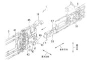
- the second module body 5 is moved in the direction of the arrow with respect to the first module body 3 from the state shown in FIG. 1, and the second module body 5 is installed in the first module body 3.
- the pair of locking claws 43 are elastically deformed so that the protrusions 53 push the pair of locking claws 43 apart from each other.
- the pair of locking claws 43 are restored, and the second module main body 5 is separated from the first module main body 3.
- the small protrusion 55 of the second module body 5 is fitted in one recess of the first module body 3, and the other recess of the first module body 3 is fitted.
- Another small protrusion 57 of the second module body 5 is fitted.
- the bus bar module 1 is placed in the state shown in FIG. 2 or the like by installing the second module body 5 in the first module body 3 from the state shown in FIG. In the state shown in FIG. 1, it is assumed that the bus bar 9 is installed in the module main bodies 3 and 5 and the output terminal 11 is installed in the first module main body 3. Further, in the state shown in FIG. 2, the output terminal cover 19 is located in the open position.
- bus bar module 1 is installed on the battery assembly, and terminals of other devices are installed on the male screw of the output terminal.
- the bus bar module 1 when the cover locked portion 23 of the output terminal cover 19 is locked to the cover locking portion 27 of the output terminal installation portion 13 provided in the first module main body portion 3, Since the reinforcing part 31 for preventing the deformation of the output terminal installation part 13 is provided in the second module main body part 5, even if the rigidity of the first module main body part 3 is low, the cover engagement of the output terminal cover 19 is possible.
- the stop portion 23 is easily engaged with the cover locking portion 27 of the output terminal installation portion 13.
- the output terminal installation portion 13 is formed in a plate shape
- the reinforcing portion 31 is formed in a plate shape
- the second module main body portion 5 is the first module main body portion 3.
- the reinforcing portion 31 overlaps with the output terminal installation portion 13 when installed on the cover, and the output terminal installation portion 13 receives from the output terminal cover 19 when the cover locked portion 23 is engaged with the cover engagement portion 27. Since the direction of the force and the thickness direction of the output terminal installation portion 13 and the reinforcement portion 31 coincide with each other, the output terminal installation portion 13 and the reinforcement portion 31 can be output without increasing the thickness dimension. The deformation of the terminal installation portion 13 can be prevented, and the cover locked portion 23 of the output terminal 11 is easily engaged with the cover locking portion 27 of the output terminal installation portion 13.
- the output terminal installation rib 35 (35A) and the reinforcement rib 39 (39A) are provided. Since they are configured to contact each other, it is possible to increase the value of the output terminal installation portion 13 and the reinforcing portion 31 and the cross-sectional secondary moment when the output terminal installation portion 13 and the reinforcing portion 31 overlap each other. In addition, the deformation of the output terminal installation portion 13 can be further prevented, and the cover locked portion 23 of the output terminal cover 19 can be more easily engaged with the cover locking portion 27 of the output terminal installation portion 13.
- the extending direction of some ribs 35 ⁇ / b> A of the output terminal installation portion ribs 35 and the extending direction of some ribs 39 ⁇ / b> A of the reinforcing portion ribs 39 are orthogonal to each other.
Landscapes
- Chemical & Material Sciences (AREA)
- Chemical Kinetics & Catalysis (AREA)
- Electrochemistry (AREA)
- General Chemical & Material Sciences (AREA)
- Connection Of Batteries Or Terminals (AREA)
- Battery Mounting, Suspending (AREA)
Description
本発明は、バスバモジュールに係り、特に、バッテリ集合体に設置されて使用されるものに関する。
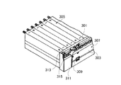
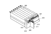
従来、図13、図14で示すように、樹脂ケース301とカバー303とを備え、バッテリ集合体305に設置されて使用されるバスバモジュール307が知られている(特許文献1参照)。
バスバモジュール307のカバー303には、ヒンジ部309を介してドア部(開閉部)311が設けられている。ドア部311には係止孔313が設けられている。樹脂ケース301には、係止爪315が設けられている。
ドア部311はヒンジ部309を支点に回動する。ドア部311を閉じると(図13参照)、電極317がドア部311で覆われる。ドア部311を開くと(図14参照)、電極317が露出する。
ドア部311を開いておくことで、電極317に外部機器からの電線を接続する作業やバッテリ集合体305の整備作業が容易になる。また、ドア部311を閉じることで、電極317が覆われ、電極317への塵埃等の付着が防止される。
ドア部311が閉じているときには、ドア部311の係止孔313に、係止爪315が係合する。この係合によって、ドア部311が固定され、ドア部311が閉じている状態を維持することができるようになっている。
また、従来の技術に関連する文献として特許文献2を掲げることができる。
ところで、従来のバスバモジュール307では、ドア部311を閉じるときに、受け側の樹脂ケース301の剛性が低くなりやすく、係止爪315が係止孔313に入り込むときに、ドア部311から受ける力で樹脂ケース301(係止爪315近傍の部位)が撓んでしまい、係止爪315が係止孔313との位置合わせと嵌合作業が困難になるという問題がある。換言すれば、樹脂ケース301(係止爪315近傍の部位)が撓むことで、係止爪315に対する係止孔313の位置ずれが発生し、係止爪(係止部)315が係止孔(被係止部)313に入り込み難くなり、ドア部311を閉じ位置に固定しにくくなるという問題がある。
本発明は、上記問題点に鑑みてなされたものであり、バッテリ集合体の各バッテリを直列接続するために前記バッテリ集合体に設置されるバスバモジュールにおいて、モジュール本体部の剛性が低くても、ヒンジカバーの被係止部がモジュール本体部の係止部と係合しやすいバスバモジュールを提供することを目的とする。
本発明の第1の態様は、バッテリ集合体の各バッテリを直列接続するために、前記バッテリ集合体に設置されて使用されるバスバモジュールである。バスバモジュールは、出力端子が設置される出力端子設置部が設けられている第1のモジュール本体部と、前記第1のモジュール本体部に対して着脱自在である第2のモジュール本体部と、前記出力端子設置部に設置された出力端子を覆うために、ヒンジ部を介して前記第1のモジュール本体部に設けられている出力端子カバーと、前記出力端子カバーに設けられているカバー被係止部と、前記第1のモジュール本体部の出力端子設置部に設けられ、前記出力端子カバーが前記出力端子設置部に設置された出力端子を覆うときに、前記出力端子カバーのカバー被係止部が係止されるカバー係止部と、前記第2のモジュール本体部に設けられ、前記第2のモジュール本体部が前記第1のモジュール本体部に設置されときに前記出力端子設置部に係合し、前記カバー被係止部が前記カバー係止部に係止されるときに前記出力端子設置部の変形を防止する補強部とを備えることを要旨とする。
前記出力端子設置部は、板状に形成されてもよい。前記補強部は、板状に形成されてもよい。前記第2のモジュール本体部が前記第1のモジュール本体部に設置されたときには、前記補強部が前記出力端子設置部に重なるように構成されてよい。前記カバー被係止部が前記カバー係止部に係止されるときに前記出力端子カバーから前記出力端子設置部が受ける反力の方向と、前記出力端子設置部と前記補強部との厚さ方向であって前記出力端子設置部から前記補強部に向かう方向とが、お互いに一致するように構成されてもよい。
前記出力端子設置部は、平板状の出力端子設置部本体部と、この出力端子設置部本体部から突出している出力端子設置部リブとを備えてもよい。前記補強部は、平板状の補強部本体部と、この補強部本体部から突出している補強部リブとを備えてもよい。前記第2のモジュール本体部が前記第1のモジュール本体部に設置されたときには、前記出力端子設置部リブと、前記補強部リブとがお互いに接触するように構成されてもよい。
前記出力端子設置部リブのうちの少なくとも一部のリブの延伸方向と、前記補強部リブのうちの少なくとも一部のリブの延伸方向とは、お互いに交差していてもよい。前記第2のモジュール本体部が前記第1のモジュール本体部に設置されたときには、前記出力端子設置部リブのうちの少なくとも一部のリブの一部の部位と、前記補強部リブのうちの少なくとも一部のリブの一部の部位とがお互いに接触するように構成されていてもよい。
本発明によれば、バッテリ集合体の各バッテリを直列接続するために前記バッテリ集合体に設置されるバスバモジュールにおいて、モジュール本体部の剛性が低くても、ヒンジカバーの被係止部がモジュール本体部の係止部と係合しやすいバスバモジュールを提供することができるという効果を奏する。
本発明の実施形態に係るバスバモジュール(バッテリ接続体)1は、従来のものと同様に、バッテリ集合体(図1~図12では図示せず)の各バッテリを直列接続するために、バッテリ集合体のたとえば側部に設置されて使用されるものである。
ここで、説明の便宜のために、バスバモジュール1における一方向を長手方向(X軸方向)とし、長手方向に対して直交する一方向を縦方向(Y軸方向)とし、長手方向と縦方向とに対して直交する方向を厚さ方向(Z軸方向)とする。
バッテリは、たとえば細長い直方体状に形成されており、この長手方向の一方の面からプラス端子とマイナス端子とが突出している。
バッテリ集合体は、お互いが同形状に形成されている複数のバッテリ(セル)で構成されている。バッテリ集合体では、各バッテリそれぞれの長手方向が、水平な一方向(バスバモジュールでは厚さ方向)になっており、お互いに一致している。バッテリ集合体では、各バッテリの長手方向の一方の面(プラス端子とマイナス端子とが突出している面)が、一平面内に位置しており、各バッテリの長手方向の他方の面が、他の一平面内に位置している。また、バッテリ集合体では、上記水平な一方向と直交する他の水平な一方向(バスバモジュールでは長手方向)に、各バッテリがお互いに接触しもしくは僅かな間隙を隔ててならんでいる。さらに、バッテリ集合体では、上下方向(バスバモジュール1では縦方向)に、上記他の水平な一方向にならんでいるバッテリが、接触しもしくは僅かな間隙を隔てて2段等の多段で重なっている。
これより、バッテリ集合体を各バッテリの長手方向(プラス端子とマイナス端子とが突出している側)から見ると、複数のバッテリが水平方向と上下方向に行列をなしてならんでいる。さらに、上記他の水平な一方向にならんでいる各バッテリのそれぞれのプラス端子とマイナス端子とが交互にならんでいる。
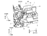
バスバモジュール1は、図1~図10で示すように、第1のモジュール本体部3と第2のモジュール本体部5とを備えて構成されている。バスバモジュール1のバスバ設置部7には、複数の金属製で平板状のバスバ9が嵌り込む等して一体的に設置されるようになっている。
バスバモジュール1に設置されたバスバ(設置済みバスバ)9のそれぞれは、バスバモジュール1がバッテリ集合体に設置されたときに、各バッテリの端子のそれぞれに接続され、バッテリ集合体の各バッテリが直列接続されるようになっている。
第1のモジュール本体部3は、たとえば、絶縁性の合成樹脂で構成されており射出成形によって生成されている。第1のモジュール本体部3には、出力端子11が設置される出力端子設置部(出力端子支持部)13が設けられている。
また、第1のモジュール本体部3には、出力端子設置部13とバスバ設置部7との他に、第1のモジュール本体部係止部15が設けられている。
出力端子11は、第1のモジュール本体部3(出力端子設置部13)に嵌り込む等して、第1のモジュール本体部3に一体的に設置されるようになっている。
出力端子11は、導電性の金属材料で構成されており、バスバモジュール1がバッテリ集合体に設置されたときに、各バスバ9で直列接続された各バッテリのうちのたとえば端部のバッテリの端子(電極)と係合して導通するようになっている。
第2のモジュール本体部5も、第1のモジュール本体部と同様にして、絶縁性の合成樹脂で構成されており、第1のモジュール本体部とは別個の射出成形によって生成されている。第2のモジュール本体部5は、第1のモジュール本体部3に対して着脱自在になっており、第1のモジュール本体部3に設置されたときに第1のモジュール本体部3と一体化するようになっている。
なお、第1のモジュール本体部3と第2のモジュール本体部5とに分割しているのは、第1のモジュール本体部3や第2のモジュール本体部5の成形に使用する金型が大型化することを防ぐためである。また、バスバモジュール1を複数のモジュール本体部3,5に分割しユニット化しておけば、直列接続されるバッテリの数が増える等しても柔軟に対応することができるからである。
第2のモジュール本体部5には、バスバ設置部7の他に、第2のモジュール本体部係止部17が設けられている。
そして、第1のモジュール本体部係止部15と第2のモジュール本体部係止部17とをお互いに係合させることで、第2のモジュール本体部5が第1のモジュール本体部3に設置され、第1のモジュール本体部3と第2のモジュール本体部5とが一体化し、この一体化したものに、バスバ9や出力端子11等を設置することで、バスバモジュール1が生成されるようになっている。
また、バスバモジュール1には、出力端子カバー(ヒンジカバー)19が設けられている。出力端子カバー19は、出力端子設置部13に設置された出力端子11を覆うためのものであり、ヒンジ部(たとえば他の部分よりも薄いセルフヒンジで構成されたヒンジ部)21を介して第1のモジュール本体部3に設けられている。また、出力端子カバー19は、ヒンジ部21とともに第1のモジュール本体部3と一体成形されている。
出力端子カバー19には、カバー被係止部23が設けられている。カバー被係止部23は、ヒンジ部21から離れたところ(たとえば、ヒンジ部21とは反対側)に位置している。
出力端子カバー19は、枡状に形成されている。枡状に形成されている出力端子カバー19の矩形状の開口部の1辺の近傍にヒンジ部21が設けられている。直線状のヒンジ部21は、第1のモジュール本体部3の出力端子設置部13から所定の距離だけ離れたところに位置している。そして、ヒンジ部21を回動中心にしてたとえば180°回動することで、出力端子カバー19が、第1のモジュール本体部3の出力端子設置部13に設置された出力端子(設置済み出力端子)11を覆い隠す位置(覆隠位置;図7等参照)と、設置済み出力端子11が露出するように設置済み出力端子11を開放する位置(開放位置;図4等参照)との間を回動するようになっている。
出力端子カバー19のカバー被係止部23は、ヒンジ部21が設けられている辺(枡状に形成されている出力端子カバー19の矩形状の開口部の1辺)と対向している他の1辺のところに設けられている。たとえば、カバー被係止部23は、他の1辺の近くに設けられた貫通孔(枡状に形成されている出力端子カバー19の側部を貫通している貫通孔)25で構成されている。
第1のモジュール本体部3の出力端子設置部13には、カバー係止部27が設けられている。カバー係止部27は、出力端子カバー19が設置済み出力端子11を覆うときに、出力端子カバー19のカバー被係止部23が係止されるものである。
出力端子カバー19が、覆隠位置に位置したときには、出力端子カバー19のカバー被係止部23が第1のモジュール本体部3のカバー係止部27に係止され、出力端子カバー19が覆隠位置で固定されるようになっている。さらに説明すると、たとえば、第1のモジュール本体部3のカバー係止部27は、第1のモジュール本体部3の出力端子設置部13(出力端子設置部13の中央に対してヒンジ部21が設けられているところとは反対側のところ)に形成された突起29で構成されている。
そして、出力端子カバー19が、覆隠位置の位置したときには、カバー係止部27の突起29が、カバー被係止部23の貫通孔25に入り込み、出力端子カバー19のカバー被係止部23が第1のモジュール本体部3のカバー係止部27に係止されるようになっている。
第2のモジュール本体部5には、補強部(出力端子設置部補強部)31が設けられている。補強部31は、第2のモジュール本体部5が第1のモジュール本体部3に設置されときに出力端子設置部13に係合し、カバー被係止部23がカバー係止部27に係止されるときに出力端子設置部13の変形を防止するようになっている。すなわち、第2のモジュール本体部5が第1のモジュール本体部3に設置されて出力端子設置部13に補強部31が係合して出力端子設置部13を支えることで、出力端子設置部13が変形し難くなっている。
そして、出力端子カバー19を開放位置から覆隠位置に位置させるべく出力端子カバー19のカバー被係止部23を第1のモジュール本体部3のカバー係止部27に係止するときに、出力端子カバー19から受ける反力で、出力端子設置部13が弾性変形することがほぼ回避されるようになっている(弾性したとしてもその量はごく僅かであり許容できる量である)。
これにより、出力端子カバー19のカバー被係止部23に対する出力端子設置部13のカバー係止部27の位置ずれがほぼ無くなり(位置ずれ量が許容値内になり)、カバー被係止部23とカバー係止部27とがお互いに係合しない事態やし難くなる事態の発生を回避することができるようになっている。
また、出力端子設置部13は、板状(たとえば平板状)に形成されており、補強部31も、板状(たとえば平板状)に形成されている。そして、第2のモジュール本体部5が第1のモジュール本体部3に設置されたときには、補強部31が出力端子設置部13に重なるように構成されている。
出力端子11は、補強部31が重なる側とは反対側で出力端子設置部13に設置されるようになっており、出力端子カバー19は、補強部31が重なる側とは反対側で設置済み出力端子11を覆うようになっている。
また、カバー被係止部23がカバー係止部27に係止されるときに出力端子カバー19から出力端子設置部13が受ける反力の方向と、出力端子設置部13と補強部31との厚さ方向であって出力端子設置部13から補強部31に向かう方向(バスバモジュール1の縦方向であって他端側から一端側に向かう方向)とが、お互いに一致するように構成されている。なお、これらの方向がお互いに一致するとは、これらが実質的に一致することを意味し、実施形態から一致とみなせる範囲を含んでいる。
出力端子設置部13は、平板状の出力端子設置部本体部33と、この出力端子設置部本体部33から突出している出力端子設置部リブ35とを備えて構成されている。補強部31は、平板状の補強部本体部37と、この補強部本体部37から突出している補強部リブ39とを備えて構成されている。
そして、第2のモジュール本体部5が第1のモジュール本体部3に設置されたときには、出力端子設置部リブ37と補強部リブ39とがお互いに接触するように構成されている(図11(a),(b)参照)。
さらに説明すると、第2のモジュール本体部5を第1のモジュール本体部3に設置した状態では、出力端子設置部リブ37が出力端子設置部本体部33から補強部31側に突出しており、補強部リブ39が補強部本体部37から出力端子設置部13側に突出しており、出力端子設置部リブ35の平面状の先端と補強部リブ39の平面状の先端とがお互いに接触している。換言すれば、板状の出力端子設置部本体部33と板状の補強部本体部37との間に、出力端子設置部リブ35と補強部リブ39とが存在している。
また、出力端子設置部リブ35のうちの少なくとも一部のリブの延伸方向と、補強部リブ39のうちの少なくとも一部のリブの延伸方向とが、お互いに交差している(たとえば直交している)。
そして、第2のモジュール本体部5が第1のモジュール本体部3に設置されたときには、出力端子設置部リブ35のうちの少なくとも一部のリブの一部の部位と、補強部リブ39のうちの少なくとも一部のリブの一部の部位とがお互いに接触するように構成されている。
たとえば、図11(a)で示すように、出力端子設置部リブ35のうちの一部のリブ35Aの延伸方向が、バスバモジュール1の厚さ方向になっており、補強部リブ39のうちの一部のリブ39Aの延伸方向が、バスバモジュール1の長手方向になっている。
そして、第2のモジュール本体部5が第1のモジュール本体部3に設置されたときには、出力端子設置部リブ35の一部のリブ35Aと、補強部リブ39の一部のリブ39Aとの交差部位で、各リブ35A,39A同士がお互いに接触するようになっている。
バスバモジュール1についてさらに説明する。
第1のモジュール本体部3は、概ね平板状に形成されている基板状部位41を備えている。バスバ設置部7は、基板状部位41に複数形成されている。
図4等で示すように、第1のモジュール本体部係止部15は、長手方向では基板状部位41の一端部に設けられており、縦方向では基板状部位41の一端側に設けられている。
第1のモジュール本体部係止部15は、長手方向で基板状部位41の一端から突出している一対の係止爪43と2つの凹部(図示せず)とで構成されている。2つ凹部のうちの一方の凹部は、一対の係止爪43の間に設けられている。
出力端子設置部13は、長手方向では基板状部位41の一端部に設けられており、縦方向では基板状部位41の中間部であって第1のモジュール本体部係止部15の2つ凹部のうちの他方の凹部のところに設けられている。また、板状に形成されている出力端子設置部13は、厚さ方向では基板状部位41から他端側に突出している。また、板状の出力端子設置部13の厚さ方向は縦方向になっている。出力端子設置部リブ35は、出力端子設置部本体部37から縦方向一端側に突出している。
ヒンジ部21は、長手方向では出力端子設置部13の一端に設けられている。ヒンジ部21での出力端子カバー19の曲げ線(回動中心線)は、バスバモジュール1の厚さ方向に延伸している。
開放位置にある出力端子カバー19は、バスバモジュール1の長手方向でヒンジ部21の一端から突出しており、縦方向他端側に開口している。
カバー係止部27は、バスバモジュール1の長手方向では出力端子設置部13の他端に設けられている。出力端子カバー19が開放位置にある場合、カバー被係止部23は、バスバモジュール1の長手方向では出力端子カバー19の一端の近傍に設けられている。
出力端子11は、平板状の素材を一箇所で90°折り曲げた「L」字状に形成されていることで、平板状の第1の部位45と平板状の第2の部位47とを備えて構成されている。
第2の部位47からは、オスねじ49が突出している。オスねじ49は、第2の部位47の厚さ方向で第1の部位45側に突出している。
出力端子11が出力端子設置部13に設置された状態では、第2の部位47が出力端子設置部13に係合し、第2の部位47の厚さ方向がバスバモジュール1の縦方向になり、オスねじ49は、第2の部位47から縦方向他端側に突出している。また、出力端子11が出力端子設置部13に設置された状態では、第1の部位45が基板状部位41に係合し、第1の部位45の厚さ方向がバスバモジュール1の厚さ方向になっている。
そして、バスバモジュール1をバッテリ集合体に設置したときには、第1の部位45がボルト(図示せず)等を介してバッテリ集合体の端子に接続され、オスねじ49には、他の機器の電線の端子が接続されるようになっている。このとき、オスねじ49への電線の端子の接続を上方からできるので、電線の端子の接続がしやすくなっている。
開放位置にある出力端子カバー19が、ヒンジ部21のところで180°回動して覆隠位置に位置すると、図7等で示すように、出力端子カバー19は、長手方向でヒンジ部21から他端側に突出するようになり、縦方向一端側に開口する。ただし、出力端子カバー19の開口部は出力端子設置部13で塞がれる。
また、覆隠位置にある出力端子カバー19は、設置済み出力端子11(第1の部位45、オスねじ49)を覆うようになっている。
第2のモジュール本体部5は、概ね平板状に形成されている基板状部位51と突出部53を備えている。突出部53は、長手方向では基板状部位41の他端部から突出しており、縦方向では基板状部位51の一端部に設けられている。バスバ設置部7は、基板状部位51に複数形成されている。
第2のモジュール本体部係止部17は、長手方向では基板状部位51の他端部に設けられており、縦方向では基板状部位51の一端側に設けられている。
さらに説明すると、第2のモジュール本体部係止部17は、長手方向で突出部53の他端側の部位と、突出部53の他端から突出している小突起55と、別の小突起57とで構成されている。
そして、図1に示す状態から第1のモジュール本体部3に対して第2のモジュール本体部5を矢印の方向に移動し、第1のモジュール本体部3に第2のモジュール本体部5を設置する途中の状態では、一対の係止爪43が突出部53に押されてお互いの間隔が開くような弾性変形をするようになっている。
第1のモジュール本体部3に第2のモジュール本体部5を設置し終えた状態では、一対の係止爪43が復元し、第2のモジュール本体部5が第1のモジュール本体部3から離れることが防止されるようになっているとともに、第1のモジュール本体部3の一方の凹部に第2のモジュール本体部5の小突起55が嵌り、第1のモジュール本体部3の他方の凹部に第2のモジュール本体部5の別の小突起57が嵌るようになっている。
バスバモジュール1は、図1に示す状態から、第1のモジュール本体部3に第2のモジュール本体部5を設置することで、図2等で示す状態になる。なお、図1の示す状態では、モジュール本体部3,5にバスバ9が設置されており、第1のモジュール本体部3に出力端子11が設置されているものとする。また、図2に示す状態では、出力端子カバー19が開放位置に位置している。
続いて、バスバモジュール1をバッテリ集合体に設置し、出力端子のオスねじに他の機器の端子を設置する。
続いて、出力端子カバー19をヒンジ部21で180°回動することで、図5~図8に示すように、出力端子カバー19が覆隠位置に位置する。
バスバモジュール1によれば、出力端子カバー19のカバー被係止部23が第1のモジュール本体部3に設けられている出力端子設置部13のカバー係止部27に係止されるときに、出力端子設置部13の変形を防止する補強部31が第2のモジュール本体部5に設けられているので、第1のモジュール本体部3の剛性が低くても、出力端子カバー19のカバー被係止部23が出力端子設置部13のカバー係止部27と係合しやくなる。
また、バスバモジュール1によれば、出力端子設置部13が板状に形成されており、補強部31が板状に形成されており、第2のモジュール本体部5が第1のモジュール本体部3に設置されたときに補強部31が出力端子設置部13に重なり、カバー被係止部23がカバー係止部27に係止されるときに出力端子カバー19から出力端子設置部13が受ける反力の方向と、出力端子設置部13と補強部31との厚さ方向でとがお互いに一致しているので、出力端子設置部13や補強部31の厚さ寸法を大きくすることなく、出力端子設置部13の変形を防止することができ、出力端子11のカバー被係止部23が出力端子設置部13のカバー係止部27と係合しやくなる。
また、バスバモジュール1によれば、第2のモジュール本体部5が第1のモジュール本体部3に設置されたときには、出力端子設置部リブ35(35A)と、補強部リブ39(39A)とがお互いに接触するように構成されているので、出力端子設置部13と補強部31とがお互いに重なったときにおける出力端子設置部13と補強部31と断面二次モーメントの値を大きくすることができ、出力端子設置部13の変形を一層防止することができ、出力端子カバー19のカバー被係止部23が出力端子設置部13のカバー係止部27に一層係合しやくなる。
図11を用いて詳しく説明すると、本発明の実施形態に係るバスバモジュール1では、(a)で示すように、板状の出力端子設置部本体部33と板状の補強部本体部37との間に、出力端子設置部リブ35と補強部リブ39とが存在しているので、出力端子設置部13と補強部31と断面二次モーメントの値が大きくなっており、出力端子設置部13が変形し難くなっている。一方、(b)で示すように、補強部を設けることなく、出力端子設置部リブ35の高さを高くしても、(a)に比べて断面二次モーメントの値が小さくなる。
また、バスバモジュール1によれば、出力端子設置部リブ35のうちの一部のリブ35Aの延伸方向と、補強部リブ39のうちの一部のリブ39Aの延伸方向とが、お互いに直交しており、第2のモジュール本体部5が第1のモジュール本体部3に設置されたときには、出力端子設置部リブ35の一部のリブ35Aの一部の部位と、補強部リブ39のうちの一部のリブ39Aの一部の部位とがお互いに接触するように構成されているので、出力端子設置部13に対する補強部31の位置ずれが多少あっても、出力端子設置部リブ35の一部と補強部リブ39の一部とがお互いに確実に接触し、出力端子カバー19のカバー被係止部23が出力端子設置部13のカバー係止部27と一層係合しやくなる。
Claims (4)
- バッテリ集合体の各バッテリを直列接続するために、前記バッテリ集合体に設置されて使用されるバスバモジュールであって、
出力端子が設置される出力端子設置部が設けられている第1のモジュール本体部と、
前記第1のモジュール本体部に対して着脱自在である第2のモジュール本体部と、
前記出力端子設置部に設置された出力端子を覆うために、ヒンジ部を介して前記第1のモジュール本体部に設けられている出力端子カバーと、
前記出力端子カバーに設けられているカバー被係止部と、
前記第1のモジュール本体部の出力端子設置部に設けられ、前記出力端子カバーが前記出力端子設置部に設置された出力端子を覆うときに、前記出力端子カバーのカバー被係止部が係止されるカバー係止部と、
前記第2のモジュール本体部に設けられ、前記第2のモジュール本体部が前記第1のモジュール本体部に設置されときに前記出力端子設置部に係合し、前記カバー被係止部が前記カバー係止部に係止されるときに前記出力端子設置部の変形を防止する補強部と、
を有することを特徴とするバスバモジュール。 - 請求項1に記載のバスバモジュールであって、
前記出力端子設置部は、板状に形成されており、
前記補強部も、板状に形成されており、
前記第2のモジュール本体部が前記第1のモジュール本体部に設置されたときには、前記補強部が前記出力端子設置部に重なるように構成されており、
前記カバー被係止部が前記カバー係止部に係止されるときに前記出力端子カバーから前記出力端子設置部が受ける反力の方向と、前記出力端子設置部と前記補強部との厚さ方向であって前記出力端子設置部から前記補強部に向かう方向とが、お互いに一致するように構成されていることを特徴とするバスバモジュール。 - 請求項2に記載のバスバモジュールであって、
前記出力端子設置部は、平板状の出力端子設置部本体部と、この出力端子設置部本体部から突出している出力端子設置部リブとを備えて構成されており、
前記補強部は、平板状の補強部本体部と、この補強部本体部から突出している補強部リブとを備えて構成されており、
前記第2のモジュール本体部が前記第1のモジュール本体部に設置されたときには、前記出力端子設置部リブと、前記補強部リブとがお互いに接触するように構成されていることを特徴とするバスバモジュール。 - 請求項3に記載のバスバモジュールであって、
前記出力端子設置部リブのうちの少なくとも一部のリブの延伸方向と、前記補強部リブのうちの少なくとも一部のリブの延伸方向とが、お互いに交差しており、前記第2のモジュール本体部が前記第1のモジュール本体部に設置されたときには、前記出力端子設置部リブのうちの少なくとも一部のリブの一部の部位と、前記補強部リブのうちの少なくとも一部のリブの一部の部位とがお互いに接触するように構成されていることを特徴とするバスバモジュール。
Priority Applications (3)
| Application Number | Priority Date | Filing Date | Title |
|---|---|---|---|
| EP13816890.1A EP2871693B1 (en) | 2012-07-09 | 2013-07-08 | Bus bar module |
| CN201380036855.3A CN104428923A (zh) | 2012-07-09 | 2013-07-08 | 汇流条模块 |
| US14/412,219 US9190651B2 (en) | 2012-07-09 | 2013-07-08 | Bus bar module |
Applications Claiming Priority (2)
| Application Number | Priority Date | Filing Date | Title |
|---|---|---|---|
| JP2012153327A JP6032978B2 (ja) | 2012-07-09 | 2012-07-09 | バスバモジュール |
| JP2012-153327 | 2012-07-09 |
Publications (1)
| Publication Number | Publication Date |
|---|---|
| WO2014010557A1 true WO2014010557A1 (ja) | 2014-01-16 |
Family
ID=49916010
Family Applications (1)
| Application Number | Title | Priority Date | Filing Date |
|---|---|---|---|
| PCT/JP2013/068647 Ceased WO2014010557A1 (ja) | 2012-07-09 | 2013-07-08 | バスバモジュール |
Country Status (5)
| Country | Link |
|---|---|
| US (1) | US9190651B2 (ja) |
| EP (1) | EP2871693B1 (ja) |
| JP (1) | JP6032978B2 (ja) |
| CN (1) | CN104428923A (ja) |
| WO (1) | WO2014010557A1 (ja) |
Cited By (1)
| Publication number | Priority date | Publication date | Assignee | Title |
|---|---|---|---|---|
| WO2015093564A1 (ja) * | 2013-12-19 | 2015-06-25 | 矢崎総業株式会社 | バスバーモジュール |
Families Citing this family (6)
| Publication number | Priority date | Publication date | Assignee | Title |
|---|---|---|---|---|
| JP5973262B2 (ja) * | 2012-07-09 | 2016-08-23 | 矢崎総業株式会社 | バスバモジュール |
| JP6002488B2 (ja) | 2012-07-20 | 2016-10-05 | 矢崎総業株式会社 | バスバモジュール |
| JP6191872B2 (ja) * | 2014-02-14 | 2017-09-06 | 株式会社オートネットワーク技術研究所 | 配線モジュール及び蓄電モジュール |
| JP2018195524A (ja) * | 2017-05-22 | 2018-12-06 | 矢崎総業株式会社 | 導電モジュール |
| JP6477858B1 (ja) * | 2017-12-28 | 2019-03-06 | 株式会社オートネットワーク技術研究所 | 接続モジュール |
| JP7205406B2 (ja) * | 2019-07-05 | 2023-01-17 | 株式会社オートネットワーク技術研究所 | 接続モジュール |
Citations (8)
| Publication number | Priority date | Publication date | Assignee | Title |
|---|---|---|---|---|
| JP2001057196A (ja) * | 1999-06-10 | 2001-02-27 | Matsushita Electric Ind Co Ltd | 組電池 |
| JP2001332235A (ja) | 2000-05-25 | 2001-11-30 | Yazaki Corp | バッテリカバー |
| JP2006120488A (ja) * | 2004-10-22 | 2006-05-11 | Yazaki Corp | バッテリ用樹脂カバーとその形成方法 |
| JP2006269103A (ja) * | 2005-03-22 | 2006-10-05 | Yazaki Corp | バッテリ接続体のカバー構造 |
| JP2008166148A (ja) * | 2006-12-28 | 2008-07-17 | Sony Corp | 電池パック |
| JP2009158334A (ja) | 2007-12-27 | 2009-07-16 | Yazaki Corp | 回路体保持ケース |
| JP2011077031A (ja) * | 2009-09-07 | 2011-04-14 | Yazaki Corp | バスバモジュール、及び、このバスバモジュールを備えた電源装置 |
| WO2013005558A1 (ja) * | 2011-07-05 | 2013-01-10 | 株式会社オートネットワーク技術研究所 | 電池配線モジュール |
Family Cites Families (7)
| Publication number | Priority date | Publication date | Assignee | Title |
|---|---|---|---|---|
| JP3707595B2 (ja) * | 1998-09-09 | 2005-10-19 | 矢崎総業株式会社 | バッテリ接続プレート |
| US6166520A (en) * | 2000-01-25 | 2000-12-26 | Delphi Technologies, Inc. | Intercell bussing system for battery pack |
| US6922332B2 (en) * | 2002-04-10 | 2005-07-26 | Furukawa Electric Co., Ltd. | Electric connection box |
| JP4114497B2 (ja) * | 2003-02-14 | 2008-07-09 | 住友電装株式会社 | 回路構成体用ケース及び回路構成体の製造方法 |
| JP5026859B2 (ja) * | 2007-05-28 | 2012-09-19 | 矢崎総業株式会社 | 電気接続箱 |
| US7499262B1 (en) * | 2007-09-11 | 2009-03-03 | Lear Corporation | Power distribution bus bar |
| KR101087036B1 (ko) * | 2008-12-17 | 2011-11-25 | 주식회사 엘지화학 | 전극단자 연결장치 및 이를 포함하는 전지모듈 어셈블리 |
-
2012
- 2012-07-09 JP JP2012153327A patent/JP6032978B2/ja active Active
-
2013
- 2013-07-08 EP EP13816890.1A patent/EP2871693B1/en active Active
- 2013-07-08 US US14/412,219 patent/US9190651B2/en active Active
- 2013-07-08 CN CN201380036855.3A patent/CN104428923A/zh active Pending
- 2013-07-08 WO PCT/JP2013/068647 patent/WO2014010557A1/ja not_active Ceased
Patent Citations (8)
| Publication number | Priority date | Publication date | Assignee | Title |
|---|---|---|---|---|
| JP2001057196A (ja) * | 1999-06-10 | 2001-02-27 | Matsushita Electric Ind Co Ltd | 組電池 |
| JP2001332235A (ja) | 2000-05-25 | 2001-11-30 | Yazaki Corp | バッテリカバー |
| JP2006120488A (ja) * | 2004-10-22 | 2006-05-11 | Yazaki Corp | バッテリ用樹脂カバーとその形成方法 |
| JP2006269103A (ja) * | 2005-03-22 | 2006-10-05 | Yazaki Corp | バッテリ接続体のカバー構造 |
| JP2008166148A (ja) * | 2006-12-28 | 2008-07-17 | Sony Corp | 電池パック |
| JP2009158334A (ja) | 2007-12-27 | 2009-07-16 | Yazaki Corp | 回路体保持ケース |
| JP2011077031A (ja) * | 2009-09-07 | 2011-04-14 | Yazaki Corp | バスバモジュール、及び、このバスバモジュールを備えた電源装置 |
| WO2013005558A1 (ja) * | 2011-07-05 | 2013-01-10 | 株式会社オートネットワーク技術研究所 | 電池配線モジュール |
Non-Patent Citations (1)
| Title |
|---|
| See also references of EP2871693A4 |
Cited By (2)
| Publication number | Priority date | Publication date | Assignee | Title |
|---|---|---|---|---|
| WO2015093564A1 (ja) * | 2013-12-19 | 2015-06-25 | 矢崎総業株式会社 | バスバーモジュール |
| JP2015118827A (ja) * | 2013-12-19 | 2015-06-25 | 矢崎総業株式会社 | バスバーモジュール |
Also Published As
| Publication number | Publication date |
|---|---|
| JP6032978B2 (ja) | 2016-11-30 |
| CN104428923A (zh) | 2015-03-18 |
| EP2871693A4 (en) | 2015-12-09 |
| US9190651B2 (en) | 2015-11-17 |
| EP2871693A1 (en) | 2015-05-13 |
| JP2014017107A (ja) | 2014-01-30 |
| EP2871693B1 (en) | 2016-06-15 |
| US20150180005A1 (en) | 2015-06-25 |
Similar Documents
| Publication | Publication Date | Title |
|---|---|---|
| JP6032978B2 (ja) | バスバモジュール | |
| JP5973262B2 (ja) | バスバモジュール | |
| EP2862215B1 (en) | Module de barre de distribution | |
| CN104471743A (zh) | 汇流条模块 | |
| JP5810697B2 (ja) | 電池配線モジュール | |
| CN101997106A (zh) | 电源设备 | |
| US9666853B2 (en) | Bus bar module | |
| JP6047343B2 (ja) | バスバーモジュール用収容部 | |
| JP2012164477A (ja) | バッテリ接続具 | |
| CN109980168A (zh) | 连接模块 | |
| US10154600B1 (en) | Cover locking structure of electrical junction box | |
| US9419302B2 (en) | Electrode constituent member for battery module | |
| KR101315664B1 (ko) | 퓨즈 유닛 | |
| WO2015093564A1 (ja) | バスバーモジュール | |
| US10892460B2 (en) | Wiring module for attachment to a power storage module | |
| JP5673495B2 (ja) | 配線モジュール | |
| CN108807737A (zh) | 电池配线模组 | |
| CN216624489U (zh) | 一种卡扣式隔离组件及电池模组 | |
| CN103918134B (zh) | 电连接箱 | |
| JP2015088307A (ja) | ヒューズユニット |
Legal Events
| Date | Code | Title | Description |
|---|---|---|---|
| 121 | Ep: the epo has been informed by wipo that ep was designated in this application |
Ref document number: 13816890 Country of ref document: EP Kind code of ref document: A1 |
|
| WWE | Wipo information: entry into national phase |
Ref document number: 14412219 Country of ref document: US |
|
| NENP | Non-entry into the national phase |
Ref country code: DE |
|
| WWE | Wipo information: entry into national phase |
Ref document number: 2013816890 Country of ref document: EP |