WO2014010664A1 - 視野計 - Google Patents
視野計 Download PDFInfo
- Publication number
- WO2014010664A1 WO2014010664A1 PCT/JP2013/068958 JP2013068958W WO2014010664A1 WO 2014010664 A1 WO2014010664 A1 WO 2014010664A1 JP 2013068958 W JP2013068958 W JP 2013068958W WO 2014010664 A1 WO2014010664 A1 WO 2014010664A1
- Authority
- WO
- WIPO (PCT)
- Prior art keywords
- measurement
- visual field
- blind spot
- coordinate system
- eye
- Prior art date
- Legal status (The legal status is an assumption and is not a legal conclusion. Google has not performed a legal analysis and makes no representation as to the accuracy of the status listed.)
- Ceased
Links
Images


Classifications
-
- A—HUMAN NECESSITIES
- A61—MEDICAL OR VETERINARY SCIENCE; HYGIENE
- A61B—DIAGNOSIS; SURGERY; IDENTIFICATION
- A61B3/00—Apparatus for testing the eyes; Instruments for examining the eyes
- A61B3/02—Subjective types, i.e. testing apparatus requiring the active assistance of the patient
- A61B3/024—Subjective types, i.e. testing apparatus requiring the active assistance of the patient for determining the visual field, e.g. perimeter types
-
- A—HUMAN NECESSITIES
- A61—MEDICAL OR VETERINARY SCIENCE; HYGIENE
- A61B—DIAGNOSIS; SURGERY; IDENTIFICATION
- A61B3/00—Apparatus for testing the eyes; Instruments for examining the eyes
- A61B3/0016—Operational features thereof
- A61B3/0025—Operational features thereof characterised by electronic signal processing, e.g. eye models
-
- A—HUMAN NECESSITIES
- A61—MEDICAL OR VETERINARY SCIENCE; HYGIENE
- A61B—DIAGNOSIS; SURGERY; IDENTIFICATION
- A61B3/00—Apparatus for testing the eyes; Instruments for examining the eyes
- A61B3/0083—Apparatus for testing the eyes; Instruments for examining the eyes provided with means for patient positioning
-
- A—HUMAN NECESSITIES
- A61—MEDICAL OR VETERINARY SCIENCE; HYGIENE
- A61B—DIAGNOSIS; SURGERY; IDENTIFICATION
- A61B3/00—Apparatus for testing the eyes; Instruments for examining the eyes
- A61B3/0091—Fixation targets for viewing direction
Definitions
- the present invention relates to a perimeter capable of examining an eye to be examined at the same position every time when measuring a visual field.
- the visual field inspection presents bright spots of various brightness and size at various locations on the dome in an environment where the subject gazes at a fixed viewpoint set at the center of the visual field dome (fixation). This is done by examining the sensitivity of each subject's retina to light stimulation by responding to the subject's response to seeing or not.
- the perimeter includes a built-in inspection algorithm for determining the position of the blind spot (for example, Patent Document 1).
- a visual field inspection the subject's eye is focused on a fixed viewpoint, and then the subject's eye is inspected first.
- the blind spot position with respect to the fixed point of the subject is measured and obtained.
- a light stimulus is given to the blind spot at random time points and it is confirmed that the subject does not respond to the light stimulus (the eye to be examined is fixed).
- the viewpoint is watched, the subject's eye will not respond even if a light stimulus is applied to the measured blind spot position), and it is confirmed that the subject is not looking at anything other than the fixation point during the examination.
- the perimeter has a chin stand and a paddle so that the face position does not move as much as possible during the visual field inspection.
- the face is fixed with a headband and the inspection is performed.
- the perimeter also has an optical system (including a fixation camera and monitor) for observing the subject's eye, and the center of the screen where the reference part such as the pupil center of the subject's eye is provided on the monitor etc. at the start or during the examination The inspection is carried out while confirming that there is no deviation from the index indicating the position (fixed viewpoint). If it is displaced, the reference part of the eye to be examined is moved to the center position and corrected by moving the chin stand up, down, left and right. As a result, the eye to be inspected can always inspect the dome center from a fixed position.
- the results of visual field measurement of the eye to be examined are accumulated in the disease state (including normal) in an appropriate database via a communication line such as the device or the Internet, and the temporal visual field fluctuations of the eye to be examined are observed.
- a communication line such as the device or the Internet
- attempts are being made to use it for diagnosis of the eye to be examined.
- the measurement position of the eye to be examined will be shifted for each examination, making it difficult to compare the measurement results at the same measurement position of the eye to be examined. This will lead to variations and reduced reliability.
- An object of the present invention is to provide a perimeter capable of performing a plurality of visual field inspections in a form in which variations in measurement positions due to rotation of the face during the visual field inspections are corrected.
- the first aspect of the present invention is a coordinate system setting means (19) for setting a measurement coordinate system (CS) for measuring the visual field of the eye to be examined (22a), and the position (M1) of the blind spot (22c) of the eye to be examined. ) And the visual field for the same eye (22a) are set at the first time point and the second time point after the first time point, respectively.
- CS measurement coordinate system
- Blind spot position storage means (11) for storing the position (M1, (r, ⁇ )) of the blind spot detected at the first time point in the memory (15) at the time of visual field measurement at the first time point, At the time of visual field measurement at the second time point, the position (M1, (r ′, ⁇ ′)) of the blind spot (22c) of the eye to be examined is detected via the blind spot position detecting means (13).
- Measurement coordinate correction means (17) for performing a correction operation to be performed,
- the visual field measurement means (19) is configured to perform visual field measurement based on the measurement coordinate system (CS N ) that matches the measurement coordinate system (CS F ) at the first time point.
- the first time point is a time point of the first visual field measurement for the eye to be examined.
- a third aspect of the present invention is characterized in that the position of the blind spot is detected by polar coordinates (r, ⁇ ) based on the visual field center (ZP) of the eye to be examined.
- each time the visual field inspection is performed the shift amount ( ⁇ ) of the blind spot position is calculated, and the measurement coordinate system (CS N ) set at the second time point is moved, by performing the correction operation to match the first time point of measurement coordinate system (CS F), based on the first point of measurement coordinate system (CS F) and matching measurement coordinate system (CS N), the second It is possible to measure the visual field at the time point, and to perform a plurality of visual field inspections with a certain amount of time in a form in which the variation in the measurement position due to the rotation of the face during the visual field inspection is corrected.
- the correction operation can be easily performed.
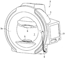
- FIG. 1 is a perspective view showing an example of a perimeter to which the present invention is applied.
- FIG. 2 is a control block diagram showing an example of a control part of the perimeter of FIG.
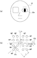
- FIG. 3 is a schematic diagram showing a relationship between a face position and visual field measurement coordinates in visual field measurement.
- FIG. 4 is a schematic diagram illustrating the relationship between the face position and the visual field measurement coordinates when the face position during the visual field measurement is rotated to the left.
- FIG. 5 is a schematic diagram illustrating a relationship between a face position and visual field measurement coordinates when the face position during visual field measurement is rotated to the right.
- the perimeter 2 has a main body 3 formed in a box shape as a whole, and a chin rest 5 and a flat pad 6 are provided on the front surface 3 a of the main body 3.
- the response switch 1 is detachably provided on the right side of the main body 3 in FIG. 1 via a connection cord 9. Further, the front of the chin rest 5 and the chin rest 6, that is, the back of the main body 3 in FIG. Inside, a hemispherical visual field dome 7 on which a visual target is presented is provided.
- the visual field dome 7 is configured such that a visual target for visual field measurement (not shown) can be projected to an arbitrary position in the visual field dome 7 by a visual target presenting unit 10 built in the main body 3 shown in FIG. Yes.
- a control unit 8 of the perimeter 2 is provided inside the main body 3, and the control unit 8 has a main control unit 11.
- the main control unit 11 includes the above-described target presentation unit 10, blind spot position detection unit 13, subject data memory 15, blind spot movement amount calculation unit 16, measurement coordinate correction unit 17, visual field measurement unit via the bus line 12. 19, an operation unit 20 such as a keyboard and a display 21 are connected.
- the control unit block diagram shown in FIG. 2 displays only the parts related to the present invention, and does not show other components of the perimeter 2 that are not related to the present invention.
- the perimeter 2 has the above configuration, when measuring the visual field of the subject's eye 22a of the subject 22, as shown in FIG. A chin is placed on the chin 6 and the chin portion 6 is pressed and brought into contact with the chin pad 6 so that the subject's eye 22a in the anterior eye portion of the subject 22 is placed at a predetermined visual field measurement position.
- the operator Since the anterior eye portion of the eye 22a of the subject 22 is displayed on the display 21 by a camera arranged in the visual field dome 7 (not shown), the operator is in the visual field dome 7 with respect to the subject 22. 1 is instructed to pay attention to the fixation point set in FIG. 1, and while viewing the image of the anterior eye portion of the eye 22a displayed on the display 21 at that time, the chin rest 5 and the heel rest 6 are moved up, down, left and right in FIG. The position is adjusted so that the eye 22a to be examined is positioned in front of the visual field dome 7, that is, in the center of the visual field dome 7.
- the positions of the chin rest 5 and the chin rest 6 are adjusted so that the eye 22a to be examined is located in front of the field dome 7, that is, in the center of the field dome 7, and the eye 22a of the subject 22 is moved from the center position of the field dome 7.
- the position of the fixation point coincides with the macular center 22b, which is the visual field center of the eye 22a to be examined.
- the main control unit 11 detects the blind spot position detection unit 13.
- a command is issued to enter the detection operation for the position M1 of the blind spot (optic nerve head) 22c.
- the detection operation of the position M1 of the blind spot 22c is performed based on a blind spot search program incorporated in the blind spot position detection unit 13 or the like. Since this is a known technique, detailed description thereof is omitted here.
- the main control unit 11 When the blind spot 22c of the blind spot position detection unit 13 searches the blind spot 22c for the macular center 22b at the position M1 and thus the position of the blind spot 22c relative to the center of the visual field, the main control unit 11 as shown in 3 (b), fixation point, i.e. the center of the field of view as a reference (origin ZP), it instructs to set the measurement coordinate system CS F for perimetry.
- fixation point i.e. the center of the field of view as a reference (origin ZP)
- it instructs to set the measurement coordinate system CS F for perimetry.
- the measurement coordinate system CS F When the measurement coordinate system CS F is set, blind spot position detection unit 13, the coordinate position of the position M1 of the detected blind spot 22c, measurement data MD of the eye 22a of the test's 22 to the subject data memory 15 As well as the ID data of the eye 11a to be examined.
- the coordinate position of the blind spot 22c is the origin ZP (field center or fixation point) detected in polar coordinates with respect, it is preferable to store (of course, even using conventional orthogonal coordinates as coordinate system CS F Good).
- the coordinates of the position M1 of the blind spot 22c are (r, ⁇ ).
- the main control unit 11 measures the visual field of the subject eye to the visual field measurement unit 19.
- the visual field measurement unit 19 sequentially presents the visual target (not shown) at an appropriate position in the visual field dome 7 by a known method.
- the visual field measurement unit 19 measures the visual field of the eye to be inspected by a known method by associating the operation state of the response switch 1 with the target position in the visual field dome 7 at that time.
- the measurement data MD corresponds to the eye 22a in the subject data memory 15 from the visual field measurement unit 19 in accordance with a command from the main control unit 11.
- the measurement data MD of the eye 22a to be examined are stored together with the coordinates (r, ⁇ ) of the position M1 of the blind point 22c with reference to the origin ZP when the measurement data MD is obtained. Since the position of the origin ZP is the center of the visual field of the subject eye 22a gazing at the fixation point as already described, as shown in FIG. 3 (b), the macular portion center 22b of the fundus oculi of the subject eye 22a. Matches the position of.
- the first visual field measurement for the eye to be examined 11a that is, the first visual field measurement is completed, and then, for example, several months later, several years later, or at regular time intervals, the second time, the third time, and the nth time
- the operator puts the chin on the chin rest 5 and presses and contacts the chin rest 6 with the chin rest 6 in the same manner as described above.
- the chin rest 5 and the chin rest 6 are moved in the form of fine adjustment in the vertical and horizontal directions in FIG. 1 to position the eye 22a in front of the visual field dome 7.
- the fixation point is set as the visual field center (macular portion center 22b) of the subject eye 22a.
- blind spot position detecting unit 13 sets a measurement coordinate system CS N to the center of the field of view as the origin ZP. Then, the coordinates (r ′, ⁇ ′) of the blind spot position M1 with respect to the visual field center (macular portion center 22b, origin ZP) are calculated and obtained.
- the position of the macular portion center 22b that is the center of the visual field, and hence the origin ZP is obtained with high accuracy at the same position as the first measurement with almost no error even if time elapses from the previous examination.
- the position M1 of the blind spot 22c differs in the contact state of the subject 22 with the chin rest 5 and the chin rest 6 for each visual field measurement, and the position of the face, that is, the eye 11a to be examined is, for example, FIG. As shown in FIG. 5 (a), it may tilt in the form of a left rotation in the figure as a whole, or as shown in FIG. 5 (a), it may be tilted in a form of a right rotation in the figure as a whole. Change.
- the main control unit 11 causes the blind point movement amount calculation unit 16 to detect the position of the blind point 22c. It is calculated how much the position is rotationally moved with respect to the origin ZP as compared with the first measurement, that is, whether or not the position is shifted.
- the blind spot movement calculation unit 16 reads the coordinates (r, ⁇ ) of the position M1 of the blind spot 22c in the first measurement stored in the subject data memory 15 for the subject eye 11a, Both azimuth angles ⁇ and ⁇ ′ are compared.
- the eye 11a to be examined is rotated leftward about the origin ZP by an angle ⁇ as shown in FIG. 4 (a), for example, the position of the blind spot 22c to be measured.
- This measurement coordinate system CS N and initially set measurement coordinate system CS F is set during this measurement, the measurement coordinate system is set when in the currently measured as shown in FIG. 4 (b) CS N
- CS F angle ⁇ ⁇ '- ⁇ rotates rightward, which means that a position displaced relationship.
- the measurement points MP which is previously set in the measurement coordinate system CS N with the rotation of the measurement coordinate system CS N, an angle ⁇ rotates to the left, the measurement points and MP which has been set in the measurement coordinate system CS F Will match.
- the main control unit 11 based on the measurement coordinate system CS N measurement points was set to MP, performs the first measurement time as well as perimetry operation, is set in the measurement coordinate system CS N measurement points MP since matches the first measuring point MP that has been set in the measurement coordinate system CS F were used in perimetry operation exactly match the beginning of each measuring point was perimetry MP position
- the current visual field measurement can be performed, and the visual field inspection can be performed in a form in which the rotation of the eye 22a of the subject 22 is corrected.
- the measurement results at each measurement point MP also correspond exactly to the measurement results at the first measurement point MP, there is no variation in the inspection results for each measurement point MP, and the reliability is improved. I can do it.
- the blind spot 22c to be measured is measured when it is rotated rightward about the origin ZP by an angle ⁇ as compared with the first measurement.
- This is the time of measurement coordinate system CS N and initially set measurement coordinate system CS F was set for the measurement, the measurement coordinate system is set when in the currently measured as shown in FIG. 5 (b) CS N
- the main control unit 11 based on the measurement coordinate system CS N measurement points was set to MP, performs the first measurement time as well as perimetry operation, is set in the measurement coordinate system CS N measurement points MP since matches the first measuring point MP that has been set in the measurement coordinate system CS F were used in perimetry operation exactly match the beginning of each measuring point was perimetry MP position
- the current visual field measurement can be performed, and the visual field inspection can be performed in a form in which the rotation of the eye 22a of the subject 22 is corrected.
- the measurement results at each measurement point MP also correspond exactly to the measurement results at the first measurement point MP, there is no variation in the inspection results for each measurement point MP, and the reliability can be improved. I can do it.
- blind spot position with respect to the origin ZP is reference point of the measurement coordinate system CS F that is set during testing (r, theta) in the memory along with the field measurements and , blind spot position measured in the measurement coordinate system CS N which is set when perimetry for the same subject's eye 22a after (r ', ⁇ ') and by comparing the blind spot position at the time of initial perimetry (r, theta) , by an amount corresponding to the deviation of the blind spot position (e.g. the angle alpha), a measurement coordinate system CS N which Saishi the field inspection after move (relative including mobile), has dealt with the case of performing this visual-field examination.
- the measurement coordinate system CS N which Saishi the field inspection after move (relative including mobile
- the present invention is not limited to the first examination and the subsequent examinations, and the first examination is performed with respect to time in the case where a plurality of visual field examinations are performed for the same eye 11a with a predetermined time.
- the present invention can also be applied to a visual field inspection performed at a time point (not limited to the first time) and a second time point thereafter.
- the first inspection (measurement) of the visual field measurement here is not necessarily the “first” visual field measurement in the subject's experience, but highly reliable visual field measurement data was obtained. It is also possible to perform the first visual field inspection performed in the normal inspection state. In other words, at the time of empirical “first” visual field measurement, or at several subsequent visual field measurements, the test subject is unfamiliar with the test, so examinations such as poor fixation, false negatives, false positive reactions, etc. It tends to cause a situation that reduces the reliability of the system. Since such low-reliability visual field measurement data is not desirable as original visual field measurement data, it is desirable not to adopt it as measurement data at the first time point.
- the first measurement of the eye 22a to be measured by the perimeter can be the first visual field measurement time when reliable visual field measurement data is obtained.
- the first perimetry can be performed. It is also possible to use the visual field measurement at the first time point.
- Blind spot position storage means main control unit
- Blind spot position detection means blind spot position detector
- Memory Subject data memory
- Blind spot movement calculation means blind spot movement calculation unit
- Measurement coordinate correction means Measurement coordinate correction unit
- Coordinate system setting means visual field measuring means (visual field measuring unit) 22a ... subject's eye 22b ... macular center 22c ... blind spots CS, CS F, CS N ... measurement coordinate system M1 ... position ZP ... field center (origin)
Landscapes
- Health & Medical Sciences (AREA)
- Life Sciences & Earth Sciences (AREA)
- Engineering & Computer Science (AREA)
- Heart & Thoracic Surgery (AREA)
- Molecular Biology (AREA)
- Biophysics (AREA)
- Ophthalmology & Optometry (AREA)
- Biomedical Technology (AREA)
- Veterinary Medicine (AREA)
- Medical Informatics (AREA)
- Physics & Mathematics (AREA)
- Surgery (AREA)
- Animal Behavior & Ethology (AREA)
- General Health & Medical Sciences (AREA)
- Public Health (AREA)
- Signal Processing (AREA)
- Eye Examination Apparatus (AREA)
Abstract
Description
前記第1の時点の視野測定際して、当該第1の時点で検出された前記盲点の位置(M1、(r,θ))をメモリ(15)に格納する盲点位置格納手段(11)、
前記第2の時点での視野測定に際して、前記盲点位置検出手段(13)を介して前記被検眼の盲点(22c)の位置(M1、(r′,θ′))を検出し、当該盲点の位置と前記メモリ(15)に格納された前記第1の時点の盲点の位置(M1、(r,θ))を読み出して、両者のずれ量(α)を演算する盲点移動量演算手段(16)、及び、
前記演算されたずれ量(α)に基づいて、前記第2の時点で設定された測定座標系(CSN)を、移動させて、前記第1の時点の測定座標系(CSF)と一致させる補正動作を行う測定座標補正手段(17)を有し、
前記視野測定手段(19)は、前記第1の時点の測定座標系(CSF)と一致した前記測定座標系(CSN)に基づいて、視野の測定を行うことを特徴として構成される。
即ち、α=θ’- θなる関係が生じる。
このことは、今回の測定に際して設定される測定座標系CSNと最初に設定された測定座標系CSFは、図4(b)に示すように今回の測定に際して設定される測定座標系CSNが最初に設定された測定座標系CSFに対して角度α=θ’- θだけ右方向に回転した、ずれた位置関係となることを意味する。
即ち、α=θ’- θなる関係が生じる(右回転では、α<0)。
このことは、今回の測定に際して設定される測定座標系CSNと最初に設定された測定座標系CSFは、図5(b)に示すように今回の測定に際して設定される測定座標系CSNが最初に設定された測定座標系CSFに対して角度α=θ’- θだけ左方向に回転した、ずれた位置関係となることを意味する。
11…盲点の位置格納手段(主制御部)
13…盲点位置検出手段(盲点位置検出部)
15…メモリ(被検者データメモリ)
16…盲点移動量演算手段(盲点移動量演算部)
17…測定座標補正手段(測定座標補正部)
19…座標系設定手段、視野測定手段(視野測定部)
22a…被検眼
22b…黄斑部中心
22c…盲点
CS、CSF、CSN…測定座標系
M1…位置
ZP…視野中心(原点)
α…ずれ量(角度)
Claims (3)
- 被検眼の視野を測定するための測定座標系を設定する座標系設定手段、前記被検眼の盲点の位置を検出する盲点位置検出手段、及び同一の被検眼につての視野を、第1の時点と、当該第1の時点の後の第2の時点において、それぞれの時点において設定された前記測定座標系を基準にして測定することの出来る視野測定手段を有する、視野計において、
前記第1の時点の視野測定際して、当該第1の時点で検出された前記盲点の位置をメモリに格納する盲点位置格納手段、
前記第2の時点での視野測定に際して、前記盲点位置検出手段を介して前記被検眼の盲点の位置を検出し、当該盲点の位置と前記メモリに格納された前記第1の時点の盲点の位置を読み出して、両者のずれ量を演算する盲点移動量演算手段、及び、
前記演算されたずれ量に基づいて、前記第2の時点で設定された測定座標系を、移動させて、前記第1の時点の測定座標系と一致させる補正動作を行う測定座標補正手段を有し、
前記視野測定手段は、前記第1の時点の測定座標系と一致した前記測定座標系に基づいて、視野の測定を行うことを特徴として構成される視野計。 - 前記第1の時点は、当該被検眼についての、最初の視野測定の時点であることを特徴とする、請求項1記載の視野計。
- 前記盲点の位置は、前記被検眼の視野中心を基準とした極座標で検出することを特徴とする、請求項1記載の視野計。
Priority Applications (3)
| Application Number | Priority Date | Filing Date | Title |
|---|---|---|---|
| EP13816943.8A EP2873363A4 (en) | 2012-07-13 | 2013-07-11 | DIOPSIMETER |
| JP2014524862A JP6266515B2 (ja) | 2012-07-13 | 2013-07-11 | 視野計 |
| US14/414,520 US20150342452A1 (en) | 2012-07-13 | 2013-07-11 | Perimeter |
Applications Claiming Priority (2)
| Application Number | Priority Date | Filing Date | Title |
|---|---|---|---|
| JP2012-157400 | 2012-07-13 | ||
| JP2012157400 | 2012-07-13 |
Publications (1)
| Publication Number | Publication Date |
|---|---|
| WO2014010664A1 true WO2014010664A1 (ja) | 2014-01-16 |
Family
ID=49916105
Family Applications (1)
| Application Number | Title | Priority Date | Filing Date |
|---|---|---|---|
| PCT/JP2013/068958 Ceased WO2014010664A1 (ja) | 2012-07-13 | 2013-07-11 | 視野計 |
Country Status (4)
| Country | Link |
|---|---|
| US (1) | US20150342452A1 (ja) |
| EP (1) | EP2873363A4 (ja) |
| JP (1) | JP6266515B2 (ja) |
| WO (1) | WO2014010664A1 (ja) |
Cited By (1)
| Publication number | Priority date | Publication date | Assignee | Title |
|---|---|---|---|---|
| JP2016140423A (ja) * | 2015-01-30 | 2016-08-08 | 株式会社ニデック | 眼科装置 |
Families Citing this family (3)
| Publication number | Priority date | Publication date | Assignee | Title |
|---|---|---|---|---|
| AU2018269372B2 (en) * | 2017-05-18 | 2020-08-06 | Welch Allyn, Inc. | Fundus image capturing |
| EP3758576A4 (en) * | 2018-03-02 | 2022-03-09 | Ohio State Innovation Foundation | SYSTEMS AND METHODS FOR MEASURING VISUAL FUNCTION MAPS |
| CN110812145B (zh) * | 2019-11-20 | 2022-02-22 | 精准视光(北京)医疗技术有限公司 | 一种视功能调整方法及装置、虚拟现实头戴式显示设备 |
Citations (1)
| Publication number | Priority date | Publication date | Assignee | Title |
|---|---|---|---|---|
| JP2008036297A (ja) | 2006-08-09 | 2008-02-21 | Kowa Co | 視野計 |
Family Cites Families (3)
| Publication number | Priority date | Publication date | Assignee | Title |
|---|---|---|---|---|
| US5061060A (en) * | 1987-09-18 | 1991-10-29 | Oculus Optikgeraete Gmbh | Apparatus and method for finding of scotomas in the eye of a person tested |
| DE19621961C2 (de) * | 1995-10-11 | 2001-05-03 | Univ Eberhard Karls | Perimetrieanordnung und Verfahren zum Untersuchen der Sehfähigkeit |
| US8668334B2 (en) * | 2006-02-27 | 2014-03-11 | Vital Art And Science Incorporated | Vision measurement and training system and method of operation thereof |
-
2013
- 2013-07-11 WO PCT/JP2013/068958 patent/WO2014010664A1/ja not_active Ceased
- 2013-07-11 US US14/414,520 patent/US20150342452A1/en not_active Abandoned
- 2013-07-11 JP JP2014524862A patent/JP6266515B2/ja active Active
- 2013-07-11 EP EP13816943.8A patent/EP2873363A4/en not_active Ceased
Patent Citations (1)
| Publication number | Priority date | Publication date | Assignee | Title |
|---|---|---|---|---|
| JP2008036297A (ja) | 2006-08-09 | 2008-02-21 | Kowa Co | 視野計 |
Non-Patent Citations (1)
| Title |
|---|
| See also references of EP2873363A4 * |
Cited By (1)
| Publication number | Priority date | Publication date | Assignee | Title |
|---|---|---|---|---|
| JP2016140423A (ja) * | 2015-01-30 | 2016-08-08 | 株式会社ニデック | 眼科装置 |
Also Published As
| Publication number | Publication date |
|---|---|
| JPWO2014010664A1 (ja) | 2016-06-23 |
| EP2873363A4 (en) | 2016-03-02 |
| EP2873363A1 (en) | 2015-05-20 |
| US20150342452A1 (en) | 2015-12-03 |
| JP6266515B2 (ja) | 2018-01-24 |
Similar Documents
| Publication | Publication Date | Title |
|---|---|---|
| CN107847122B (zh) | 视野计测方法、视野计测装置和视力检查视标 | |
| JP5975126B2 (ja) | 眼底観察装置及び眼底観察プログラム | |
| CN103222851B (zh) | 眼科设备和眼科设备的控制方法 | |
| JP7223491B2 (ja) | 自覚式検眼装置及び自覚式検眼プログラム | |
| JP6716752B2 (ja) | 眼科装置 | |
| US10307058B2 (en) | Ophthalmologic apparatus | |
| JP7298134B2 (ja) | 検眼システム | |
| CN106963335A (zh) | 主观式检眼装置 | |
| US20110128498A1 (en) | Eye refractive power measurement apparatus | |
| CN103082989B (zh) | 眼科设备和眼科方法 | |
| JP6266515B2 (ja) | 視野計 | |
| JP2016193067A (ja) | 視野計 | |
| JP2020054784A (ja) | 眼科装置 | |
| JP2018047049A (ja) | 自覚式検眼装置、及び自覚式検眼プログラム | |
| JP2014140474A (ja) | 眼科撮影装置および撮影制御プログラム | |
| JP6418766B2 (ja) | 断層画像処理装置、断層画像処理方法及びプログラム | |
| JP6922338B2 (ja) | 自覚式検眼装置 | |
| US20210196114A1 (en) | Ophthalmic device | |
| CN110547757A (zh) | 眼屈光力测量设备以及方法 | |
| US7357506B2 (en) | Eye refractive power measurement apparatus | |
| JP6892540B2 (ja) | 眼科装置 | |
| CN117752294A (zh) | 眼科装置 | |
| JP7320574B2 (ja) | 眼科装置 | |
| JP2019176974A (ja) | 眼科用情報処理プログラム、眼科装置、および、ウェアラブルデバイス | |
| CN113100705A (zh) | Hess屏自动记录方法、系统及计算机相关产品 |
Legal Events
| Date | Code | Title | Description |
|---|---|---|---|
| 121 | Ep: the epo has been informed by wipo that ep was designated in this application |
Ref document number: 13816943 Country of ref document: EP Kind code of ref document: A1 |
|
| ENP | Entry into the national phase |
Ref document number: 2014524862 Country of ref document: JP Kind code of ref document: A |
|
| NENP | Non-entry into the national phase |
Ref country code: DE |
|
| WWE | Wipo information: entry into national phase |
Ref document number: 2013816943 Country of ref document: EP |
|
| WWE | Wipo information: entry into national phase |
Ref document number: 14414520 Country of ref document: US |