WO2014013562A1 - Machine de sérigraphie - Google Patents
Machine de sérigraphie Download PDFInfo
- Publication number
- WO2014013562A1 WO2014013562A1 PCT/JP2012/068161 JP2012068161W WO2014013562A1 WO 2014013562 A1 WO2014013562 A1 WO 2014013562A1 JP 2012068161 W JP2012068161 W JP 2012068161W WO 2014013562 A1 WO2014013562 A1 WO 2014013562A1
- Authority
- WO
- WIPO (PCT)
- Prior art keywords
- screen printing
- power saving
- printing machine
- screen
- circuit board
- Prior art date
- Legal status (The legal status is an assumption and is not a legal conclusion. Google has not performed a legal analysis and makes no representation as to the accuracy of the status listed.)
- Ceased
Links
Images

Classifications
-
- B—PERFORMING OPERATIONS; TRANSPORTING
- B41—PRINTING; LINING MACHINES; TYPEWRITERS; STAMPS
- B41F—PRINTING MACHINES OR PRESSES
- B41F33/00—Indicating, counting, warning, control or safety devices
-
- B—PERFORMING OPERATIONS; TRANSPORTING
- B41—PRINTING; LINING MACHINES; TYPEWRITERS; STAMPS
- B41F—PRINTING MACHINES OR PRESSES
- B41F15/00—Screen printers
- B41F15/02—Manually-operable devices
- B41F15/06—Manually-operable devices with auxiliary equipment, e.g. for drying printed articles
-
- B—PERFORMING OPERATIONS; TRANSPORTING
- B41—PRINTING; LINING MACHINES; TYPEWRITERS; STAMPS
- B41F—PRINTING MACHINES OR PRESSES
- B41F15/00—Screen printers
- B41F15/08—Machines
-
- B—PERFORMING OPERATIONS; TRANSPORTING
- B41—PRINTING; LINING MACHINES; TYPEWRITERS; STAMPS
- B41F—PRINTING MACHINES OR PRESSES
- B41F15/00—Screen printers
- B41F15/14—Details
-
- B—PERFORMING OPERATIONS; TRANSPORTING
- B41—PRINTING; LINING MACHINES; TYPEWRITERS; STAMPS
- B41F—PRINTING MACHINES OR PRESSES
- B41F33/00—Indicating, counting, warning, control or safety devices
- B41F33/04—Tripping devices or stop-motions
Definitions
- This application relates to a screen printing machine.
- Japanese Patent Application Laid-Open No. 2001-320199 reduces the power supplied to the self-device when it is determined that the downstream production device cannot carry the circuit board in the surface mounter. A technique for achieving electric power is described.
- Japanese Patent Laid-Open No. 2012-43899 discloses a technique for reducing power consumption in a surface mounter by cutting off the supply of power to a display lamp and an operation screen during a period when the operator is not operating. Are listed.
- the screen printing machine includes a selection unit configured to select to operate in one or both of the first power saving mode and the second power saving mode, and when the first power saving mode is selected, the operator operates the operation unit.
- a predetermined time elapses without being operated, the power supply to the light source device selected in advance is controlled to stop, and when the second power saving mode is selected, a preset power saving standby period is set.
- a control device that controls to stop the power supply to the fluid machine selected in advance.
- the screen printer when the first power saving mode is selected by the selection unit, power supply to the light source device selected in advance is stopped during a period when the operator does not operate the operation unit.
- the screen printer can be selected by selecting a light source device that does not affect the screen printing even if the power supply is stopped, such as a display lamp or an operation screen, as the light source device that stops the power supply. The power can be saved without lowering the throughput.
- the power supply to the fluid machine selected in advance is stopped during a preset power saving standby time.
- the power supply to a fluid machine is stopped, it takes some time to restart the fluid machine and return to the state where the screen printer can be operated normally. This will reduce the throughput of the machine.
- a power saving standby period a period that does not affect the throughput of the production line even if the fluid machine is stopped and restarted, such as a production line downtime, is set.
- power saving can be achieved without reducing the throughput of the production line.
- the screen printing machine according to the present embodiment can be configured such that the power saving standby period is set based on the takt time of the screen printing machine and the takt time of the downstream production apparatus. With such a configuration, it is possible to appropriately set a power saving standby period that does not decrease the throughput of the production line.
- the screen printing machine can be configured such that the preselected fluid machine includes an air conditioner for air-conditioning the inside of the screen printing machine. If the power supply of the air conditioner for air conditioning the inside of the screen printing machine is stopped, the temperature inside the screen printing machine will change, and after restarting the air conditioner, the temperature will be suitable for screen printing. A certain amount of time is required before returning. According to the above-mentioned screen printing machine, by appropriately setting the power saving standby period, unnecessary power supply to the air conditioner can be reduced without reducing the throughput of the production line, thereby saving power. Can be realized.
- the screen printing machine of the present embodiment can be configured such that the preselected fluid machine includes a vacuum pump for sucking and holding the circuit board. If the power supply to the vacuum pump for sucking and holding the circuit board is stopped, a certain amount of time will be required until the negative pressure required for sucking the circuit board is realized after the vacuum pump is restarted. Necessary. According to the above-mentioned screen printing machine, by appropriately setting the power saving standby period, unnecessary power supply to the vacuum pump can be reduced and power saving can be achieved without reducing the throughput of the production line. Can be realized.
- the screen printing machine of the present embodiment can be configured so that the control device further controls the acceleration of the servo motor when the second power saving mode is selected.
- the screen printing machine of the present embodiment can be configured such that the control device further controls to reduce the speed of the servo motor when the second power saving mode is selected. If the acceleration or speed of the servo motor is reduced, the throughput of the screen printing machine decreases. However, for example, when the throughput of the downstream production apparatus is originally lower than the throughput of the screen printer, the throughput of the production line does not decrease even if the throughput of the screen printer is reduced. According to the above-mentioned screen printing machine, by appropriately setting the power saving standby period, the power supply to the servo motor is reduced and the power saving is realized without reducing the throughput of the production line. be able to.
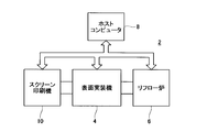
- the screen printer 10 is used in a part of the production line 2 together with the production apparatuses 4 and 6.
- the screen printer 10 screen-prints the cream solder on the circuit board to be carried in, and carries the circuit board to the production apparatus 4 on the downstream side.
- the production apparatus 4 is, for example, a surface mounter that mounts electronic components on a circuit board.
- the production apparatus 6 is, for example, a reflow furnace that heats a circuit board to melt cream solder.
- the operation of the apparatus of the production line 2 including the screen printer 10 and the production apparatuses 4 and 6 is controlled by the host computer 8.
- the screen printing machine 10 includes a circuit board transfer device 12, an air conditioner 14, a circuit board holding device 16, a mask holding device 18, a solder application device 20, an interface device 22, and a control.
- a device 24 is provided.
- the circuit board transport device 12 includes an in-conveyor that carries in the circuit board, a main conveyor that carries the circuit board inside the screen printing machine 10, an out-conveyor that carries out the circuit board, and the like.
- the circuit board transport device 12 includes a plurality of servo motors 30 that independently circulate the in-conveyor, the main conveyor, and the out-conveyor.
- the air conditioner 14 air-conditions the inside of the screen printing machine 10 and maintains the temperature suitable for screen printing. For example, when an electronic component is mounted on the front surface of the circuit board and then further mounted on the back surface, the circuit board that has become hot due to the reflow process on the front surface is not cooled sufficiently in the screen printer 10. May be brought in. When the air conditioner 14 air-conditions the inside of the screen printing machine 10, the circuit board is cooled to an appropriate temperature, and it is possible to appropriately perform screen printing on the circuit board.
- the air conditioner 14 includes, for example, a fan 32 that introduces external air into the screen printing machine 10 and discharges the air inside the screen printing machine 10 to the outside, and a temperature sensor 34.
- the circuit board holding device 16 moves and holds the circuit board conveyed by the circuit board conveying apparatus 12 to the circuit board holding position for screen printing.
- the circuit board holding device 16 includes a moving mechanism 36 that moves the circuit board conveyed by the main conveyor of the circuit board conveying apparatus 12 to the circuit board holding position, and a clamp mechanism 38 that holds the circuit board moved to the circuit board holding position. It has.
- the moving mechanism 36 includes, for example, an actuator 40 that pushes up the circuit board from below to above.
- the clamp mechanism 38 includes a servo motor 42 for driving a clamp that holds the circuit board at the circuit board holding position, and a vacuum pump 44 that generates a negative pressure to attract the circuit board to the clamp.
- the mask holding device 18 holds the screen mask for screen printing so as to cover the upper surface of the circuit board held at the circuit board holding position by the circuit board holding device 16.
- through holes are formed corresponding to a pattern for printing cream solder on the circuit board.
- the solder coating apparatus 20 supplies cream solder to the upper surface of the screen mask, and slides the squeegee along the upper surface of the screen mask, thereby printing the cream solder on the upper surface of the circuit board.
- the solder application device 20 includes a plurality of servo motors 46 for driving the squeegee biaxially.
- the interface device 22 includes a touch panel 48, a display lamp 50, and an in-machine illumination 52.
- the touch panel 48 is provided on the front surface of the screen printer 10.
- the touch panel 48 presents information about the state of the screen printing machine 10 to the worker and accepts an operation input by the worker.
- the touch panel 48 can also be referred to as an operation unit of the screen printing machine 10.
- the touch panel 48 includes a backlight 54 for displaying a screen.
- the display lamp 50 is provided separately from the touch panel 48 and notifies the operator of the state of the screen printing machine 10 through the lighting state.
- the in-machine illumination 52 illuminates the inside of the screen printing machine 10 so that an operator can easily see the state inside the screen printing machine 10.
- the control device 24 controls operations of the circuit board transfer device 12, the air conditioner 14, the circuit board holding device 16, the mask holding device 18, the solder application device 20, and the interface device 22.
- the control device 24 can communicate with the host computer 8.
- the control device 24 receives from the host computer 8 a command regarding an operation to be executed by the screen printer 10.
- the control device 24 outputs information about the state of the screen printer 10 to the host computer 8.
- the screen printer 10 can operate in the first power saving mode and / or the second power saving mode.
- the first power saving mode and the second power saving mode will be described.
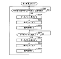
- step S302 the control device 24 determines whether or not the time during which the operator does not operate the touch panel 48 has reached a predetermined switching time. If the time during which the operator does not operate the touch panel 48 has not reached the switching time (NO in step S302), the process stands by in step S302. When the time during which the operator is not operating reaches the switching time (YES in step S302), the process proceeds to step S304.
- step S304 the control device 24 turns off the backlight 54 and turns off the display on the touch panel 48.
- step S306 the control device 24 turns off the display lamp 50.
- step S308 the control device 24 turns off the in-machine lighting 52.
- the backlight 54, the display lamp 50, and the in-machine lighting 52 of the touch panel 48 are turned off by the processing from step S304 to step S308.
- the light source devices such as the backlight 54 of the touch panel 48, the display lamp 50, and the in-machine lighting 52 are all used by the operator to check the state of the screen printing machine 10, and these light source devices are turned off. Even if this is done, the throughput of the screen printer 10 is not affected. Therefore, when the operator selects the first power saving mode, power saving can be achieved without reducing the throughput of the production line 2.
- step S310 the control device 24 determines whether or not the operator has touched the touch panel 48. If the operator is not touching the touch panel 48 (NO in step S310), the process waits in step S310 as it is. When the operator touches touch panel 48 (YES in step S310), the process proceeds to step S312.
- step S312 the control device 24 turns on the backlight 54 and turns on the display of the touch panel 48.
- step S314 the control device 24 turns on the display lamp 50.
- step S316 the control device 24 turns on the in-flight 52. After step S316, the process returns to step S302.
- the configuration in which all of the backlight 54, the display lamp 50, and the interior lighting 52 are turned off in the first power saving mode has been described. However, any one of the backlight 54, the display lamp 50, and the interior lighting 52 is described. Only two of the backlight 54, the display lamp 50, and the in-flight 52 may be turned off. Further, in the first power saving mode, the length of the switching time until the backlight 54, the display lamp 50, and the in-machine lighting 52 are turned off (that is, the switching time used as a criterion for determination in step S302) is determined using the touch panel 48. An operator may be configured to input in advance, or may be configured to be specified in advance from the host computer 8.
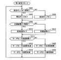
- step S402 the control device 24 determines whether or not a preset vacuum pump off period is met. When it is determined that it corresponds to the vacuum pump-off period (YES in step S402), the process proceeds to step S404, and the control device 24 turns off the vacuum pump 44. If it is determined that the vacuum pump off period is not satisfied (NO in step S402), the process proceeds to step S406, and the control device 24 turns on the vacuum pump 44.
- the above vacuum pump off period is designated in advance by the host computer 8.
- the host computer 8 sets a vacuum pump off period in accordance with a period during which production work in the production line 2 is suspended, such as a lunch break.
- a certain amount of time is required after the vacuum pump 44 is turned on again until a negative pressure capable of attracting the circuit board is obtained again. Therefore, the host computer 8 sets the end time of the vacuum pump off period so that a negative pressure capable of attracting the circuit board by the vacuum pump 44 is realized at the time when the period during which the production operation is suspended is completed.
- step S408 the control device 24 determines whether or not a preset air conditioner off period is met. If it is determined that the air conditioner OFF period is met (YES in step S408), the process proceeds to step S410, and the control device 24 turns off the air conditioner 14. If it is determined that the air conditioner OFF period is not met (NO in step S408), the process proceeds to step S412 and the control device 24 turns on the air conditioner 14.
- the air conditioner off period is specified in advance by the host computer 8.
- the host computer 8 sets an air conditioner off period in accordance with a period during which production work in the production line 2 is suspended, such as a lunch break.
- a period during which production work in the production line 2 is suspended, such as a lunch break.
- the host computer 8 sets an end time of the air conditioner off period so that an appropriate in-machine temperature is realized by the air conditioner 14 at the time when the period during which the production work is suspended ends.
- the vacuum pump 44 and the air conditioner 14 can be referred to as a pre-selected fluid machine that stops power supply in the second power saving mode.
- the vacuum pump off period and the air conditioner off period can be referred to as a power saving standby period in which the power supply to the fluid machine is stopped.
- the host computer 8 may determine the vacuum pump off period and the air conditioner off period based on the production plan in the production line 2. For example, based on the takt time of the screen printing machine 10 and the takt time of the downstream production apparatus 4, the host computer 8 determines a pause time zone in which the throughput of the production line 2 does not decrease even if the screen printer 10 is paused.
- the vacuum pump off period and the air conditioner off period can be set in accordance with the resting period. By adopting such a configuration, it is possible to save power without reducing the throughput of the production line 2.
- step S414 the control device 24 determines whether or not a preset servo motor deceleration period is met. If it is determined that it falls within the servo motor deceleration period (YES in step S414), in step S416, the control device 24 reduces the acceleration of the servomotors 30, 42, 46, and in step S418, the control device 24 The speed of the servo motors 30, 42, 46 is reduced. If it is determined that the servo motor deceleration period is not applicable (NO in step S414), in step S420, the control device 24 returns the acceleration of the servo motors 30, 42, and 46 as usual, and in step S422, The controller 24 restores the speeds of the servo motors 30, 42, 46 as usual.
- step S416 and step S418, by reducing the acceleration and speed of the servo motors 30, 42, 46, the throughput of the screen printer 10 is lowered.
- the accelerations and speeds of the servo motors 30, 42, and 46 are adapted to match the throughput of the downstream production apparatus 4. Is reduced, the throughput of the production line 2 does not decrease. Accordingly, the throughput of the production line 2 is reduced by the host computer 8 setting the servo motor deceleration period appropriately in advance based on the tact time of the screen printing machine 10 and the tact time of the downstream production apparatus 4. It is possible to save power without causing it to occur.
- the power supply to the vacuum pump 44 is stopped, the power supply to the air conditioner 14 is stopped, and the power supplied to the servomotors 30, 42, and 46 is all reduced.
- the power supply to the air conditioner 14 is stopped, and the power supplied to the servomotors 30, 42, and 46 is all reduced.
- the above-described vacuum pump off period, air conditioner off period, and servo motor deceleration period may be configured to be directly input by the operator using the touch panel 48.
Landscapes
- Engineering & Computer Science (AREA)
- Mechanical Engineering (AREA)
- Screen Printers (AREA)
- Electric Connection Of Electric Components To Printed Circuits (AREA)
Priority Applications (2)
| Application Number | Priority Date | Filing Date | Title |
|---|---|---|---|
| PCT/JP2012/068161 WO2014013562A1 (fr) | 2012-07-18 | 2012-07-18 | Machine de sérigraphie |
| JP2014525597A JPWO2014013562A1 (ja) | 2012-07-18 | 2012-07-18 | スクリーン印刷機 |
Applications Claiming Priority (1)
| Application Number | Priority Date | Filing Date | Title |
|---|---|---|---|
| PCT/JP2012/068161 WO2014013562A1 (fr) | 2012-07-18 | 2012-07-18 | Machine de sérigraphie |
Publications (1)
| Publication Number | Publication Date |
|---|---|
| WO2014013562A1 true WO2014013562A1 (fr) | 2014-01-23 |
Family
ID=49948417
Family Applications (1)
| Application Number | Title | Priority Date | Filing Date |
|---|---|---|---|
| PCT/JP2012/068161 Ceased WO2014013562A1 (fr) | 2012-07-18 | 2012-07-18 | Machine de sérigraphie |
Country Status (2)
| Country | Link |
|---|---|
| JP (1) | JPWO2014013562A1 (fr) |
| WO (1) | WO2014013562A1 (fr) |
Cited By (2)
| Publication number | Priority date | Publication date | Assignee | Title |
|---|---|---|---|---|
| EP3240304A1 (fr) | 2016-04-26 | 2017-11-01 | Isovolta AG | Membrane acoustique |
| JP2023041131A (ja) * | 2021-09-13 | 2023-03-24 | パナソニックIpマネジメント株式会社 | 部品搭載装置 |
Citations (6)
| Publication number | Priority date | Publication date | Assignee | Title |
|---|---|---|---|---|
| JPH0532018A (ja) * | 1991-07-30 | 1993-02-09 | Canon Inc | 情報処理方法及び装置 |
| JPH08242322A (ja) * | 1995-03-06 | 1996-09-17 | Ricoh Co Ltd | 画像記録装置 |
| JP2002094713A (ja) * | 2000-09-13 | 2002-03-29 | Ricoh Co Ltd | 画像処理装置 |
| WO2004103708A1 (fr) * | 2003-05-16 | 2004-12-02 | Printing Research, Inc. | Systeme a selection de zones pour le sechage aux uv pour une presse d'imprimerie |
| JP2007053340A (ja) * | 2005-07-19 | 2007-03-01 | Matsushita Electric Ind Co Ltd | 基板在庫数シミュレーション方法 |
| JP2012043899A (ja) * | 2010-08-17 | 2012-03-01 | Fuji Mach Mfg Co Ltd | 対回路基板作業システムおよび電子回路部品装着システム |
Family Cites Families (5)
| Publication number | Priority date | Publication date | Assignee | Title |
|---|---|---|---|---|
| JPH07125175A (ja) * | 1993-11-08 | 1995-05-16 | Sanyo Electric Co Ltd | スクリーン印刷機 |
| JP5236334B2 (ja) * | 2008-04-03 | 2013-07-17 | 富士機械製造株式会社 | スクリーン印刷方法及び基板温度調節機能付きスクリーン印刷装置 |
| JP5719144B2 (ja) * | 2010-11-01 | 2015-05-13 | 富士機械製造株式会社 | スクリーン印刷ライン |
| JP2011249646A (ja) * | 2010-05-28 | 2011-12-08 | Fuji Mach Mfg Co Ltd | 動作時間調整方法 |
| JP2012069587A (ja) * | 2010-09-21 | 2012-04-05 | Fuji Mach Mfg Co Ltd | 対回路基板作業機および対回路基板作業システム |
-
2012
- 2012-07-18 WO PCT/JP2012/068161 patent/WO2014013562A1/fr not_active Ceased
- 2012-07-18 JP JP2014525597A patent/JPWO2014013562A1/ja active Pending
Patent Citations (6)
| Publication number | Priority date | Publication date | Assignee | Title |
|---|---|---|---|---|
| JPH0532018A (ja) * | 1991-07-30 | 1993-02-09 | Canon Inc | 情報処理方法及び装置 |
| JPH08242322A (ja) * | 1995-03-06 | 1996-09-17 | Ricoh Co Ltd | 画像記録装置 |
| JP2002094713A (ja) * | 2000-09-13 | 2002-03-29 | Ricoh Co Ltd | 画像処理装置 |
| WO2004103708A1 (fr) * | 2003-05-16 | 2004-12-02 | Printing Research, Inc. | Systeme a selection de zones pour le sechage aux uv pour une presse d'imprimerie |
| JP2007053340A (ja) * | 2005-07-19 | 2007-03-01 | Matsushita Electric Ind Co Ltd | 基板在庫数シミュレーション方法 |
| JP2012043899A (ja) * | 2010-08-17 | 2012-03-01 | Fuji Mach Mfg Co Ltd | 対回路基板作業システムおよび電子回路部品装着システム |
Cited By (3)
| Publication number | Priority date | Publication date | Assignee | Title |
|---|---|---|---|---|
| EP3240304A1 (fr) | 2016-04-26 | 2017-11-01 | Isovolta AG | Membrane acoustique |
| WO2017186726A1 (fr) | 2016-04-26 | 2017-11-02 | Isovolta Ag | Membrane acoustique |
| JP2023041131A (ja) * | 2021-09-13 | 2023-03-24 | パナソニックIpマネジメント株式会社 | 部品搭載装置 |
Also Published As
| Publication number | Publication date |
|---|---|
| JPWO2014013562A1 (ja) | 2016-06-30 |
Similar Documents
| Publication | Publication Date | Title |
|---|---|---|
| CN102783269B (zh) | 部件安装装置和在部件安装装置中的产品类型转换方法 | |
| JP5440486B2 (ja) | 部品実装装置および部品実装装置における機種切替え方法 | |
| WO2015063934A1 (fr) | Dispositif de montage de composant | |
| JP4942497B2 (ja) | 電子部品装着装置 | |
| WO2014013562A1 (fr) | Machine de sérigraphie | |
| JP5516446B2 (ja) | 部品実装装置および部品実装方法 | |
| JP7430107B2 (ja) | 基板作業システム、基板作業ライン用の電源スイッチおよび基板作業ラインの電源管理方法。 | |
| JP5662875B2 (ja) | スクリーン印刷装置 | |
| JP2010098213A (ja) | 電子部品実装装置のメンテナンス支援装置及び電子部品実装装置のメンテナンス支援方法 | |
| KR101471900B1 (ko) | 기판 처리 장치 | |
| JP5722123B2 (ja) | 対基板作業機 | |
| JP6441469B2 (ja) | モータ駆動装置 | |
| JPWO2016166877A1 (ja) | 部品実装機の駆動システム | |
| JP5617471B2 (ja) | 電子部品実装用装置および電子部品実装用作業実行方法 | |
| JP2011204908A (ja) | 基板クランプ装置 | |
| CN105960834A (zh) | 电子元件安装装置 | |
| JP5835993B2 (ja) | 生産管理装置および部品実装システム | |
| JP4792346B2 (ja) | 電子部品装着装置及び電子部品装着方法 | |
| JP6691039B2 (ja) | 最適化プログラム、および装着作業システム | |
| CN102036546A (zh) | 电路板装配作业装置及电路板装配作业装置中的控制方法 | |
| JP5970401B2 (ja) | 実装作業装置におけるモータ制御方法及び実装作業装置 | |
| JPH0685489A (ja) | 作業装置 | |
| WO2015097732A1 (fr) | Dispositif de travail de substrat | |
| JP2012199319A (ja) | 電子部品装着装置 | |
| JP5905732B2 (ja) | 対基板作業システム |
Legal Events
| Date | Code | Title | Description |
|---|---|---|---|
| 121 | Ep: the epo has been informed by wipo that ep was designated in this application |
Ref document number: 12881375 Country of ref document: EP Kind code of ref document: A1 |
|
| ENP | Entry into the national phase |
Ref document number: 2014525597 Country of ref document: JP Kind code of ref document: A |
|
| NENP | Non-entry into the national phase |
Ref country code: DE |
|
| 122 | Ep: pct application non-entry in european phase |
Ref document number: 12881375 Country of ref document: EP Kind code of ref document: A1 |