WO2014013747A1 - 燃料電池 - Google Patents
燃料電池 Download PDFInfo
- Publication number
- WO2014013747A1 WO2014013747A1 PCT/JP2013/055718 JP2013055718W WO2014013747A1 WO 2014013747 A1 WO2014013747 A1 WO 2014013747A1 JP 2013055718 W JP2013055718 W JP 2013055718W WO 2014013747 A1 WO2014013747 A1 WO 2014013747A1
- Authority
- WO
- WIPO (PCT)
- Prior art keywords
- gas flow
- flow path
- gas
- water
- fuel cell
- Prior art date
- Legal status (The legal status is an assumption and is not a legal conclusion. Google has not performed a legal analysis and makes no representation as to the accuracy of the status listed.)
- Ceased
Links
Images







Classifications
-
- H—ELECTRICITY
- H01—ELECTRIC ELEMENTS
- H01M—PROCESSES OR MEANS, e.g. BATTERIES, FOR THE DIRECT CONVERSION OF CHEMICAL ENERGY INTO ELECTRICAL ENERGY
- H01M8/00—Fuel cells; Manufacture thereof
- H01M8/02—Details
- H01M8/0202—Collectors; Separators, e.g. bipolar separators; Interconnectors
- H01M8/0258—Collectors; Separators, e.g. bipolar separators; Interconnectors characterised by the configuration of channels, e.g. by the flow field of the reactant or coolant
-
- H—ELECTRICITY
- H01—ELECTRIC ELEMENTS
- H01M—PROCESSES OR MEANS, e.g. BATTERIES, FOR THE DIRECT CONVERSION OF CHEMICAL ENERGY INTO ELECTRICAL ENERGY
- H01M8/00—Fuel cells; Manufacture thereof
- H01M8/04—Auxiliary arrangements, e.g. for control of pressure or for circulation of fluids
- H01M8/04291—Arrangements for managing water in solid electrolyte fuel cell systems
-
- H—ELECTRICITY
- H01—ELECTRIC ELEMENTS
- H01M—PROCESSES OR MEANS, e.g. BATTERIES, FOR THE DIRECT CONVERSION OF CHEMICAL ENERGY INTO ELECTRICAL ENERGY
- H01M8/00—Fuel cells; Manufacture thereof
- H01M8/02—Details
- H01M8/0202—Collectors; Separators, e.g. bipolar separators; Interconnectors
- H01M8/0258—Collectors; Separators, e.g. bipolar separators; Interconnectors characterised by the configuration of channels, e.g. by the flow field of the reactant or coolant
- H01M8/0265—Collectors; Separators, e.g. bipolar separators; Interconnectors characterised by the configuration of channels, e.g. by the flow field of the reactant or coolant the reactant or coolant channels having varying cross sections
-
- H—ELECTRICITY
- H01—ELECTRIC ELEMENTS
- H01M—PROCESSES OR MEANS, e.g. BATTERIES, FOR THE DIRECT CONVERSION OF CHEMICAL ENERGY INTO ELECTRICAL ENERGY
- H01M8/00—Fuel cells; Manufacture thereof
- H01M8/02—Details
- H01M8/0271—Sealing or supporting means around electrodes, matrices or membranes
- H01M8/0276—Sealing means characterised by their form
-
- H—ELECTRICITY
- H01—ELECTRIC ELEMENTS
- H01M—PROCESSES OR MEANS, e.g. BATTERIES, FOR THE DIRECT CONVERSION OF CHEMICAL ENERGY INTO ELECTRICAL ENERGY
- H01M8/00—Fuel cells; Manufacture thereof
- H01M8/04—Auxiliary arrangements, e.g. for control of pressure or for circulation of fluids
- H01M8/04082—Arrangements for control of reactant parameters, e.g. pressure or concentration
- H01M8/04089—Arrangements for control of reactant parameters, e.g. pressure or concentration of gaseous reactants
-
- H—ELECTRICITY
- H01—ELECTRIC ELEMENTS
- H01M—PROCESSES OR MEANS, e.g. BATTERIES, FOR THE DIRECT CONVERSION OF CHEMICAL ENERGY INTO ELECTRICAL ENERGY
- H01M8/00—Fuel cells; Manufacture thereof
- H01M8/04—Auxiliary arrangements, e.g. for control of pressure or for circulation of fluids
- H01M8/04082—Arrangements for control of reactant parameters, e.g. pressure or concentration
- H01M8/04089—Arrangements for control of reactant parameters, e.g. pressure or concentration of gaseous reactants
- H01M8/04119—Arrangements for control of reactant parameters, e.g. pressure or concentration of gaseous reactants with simultaneous supply or evacuation of electrolyte; Humidifying or dehumidifying
- H01M8/04126—Humidifying
-
- H—ELECTRICITY
- H01—ELECTRIC ELEMENTS
- H01M—PROCESSES OR MEANS, e.g. BATTERIES, FOR THE DIRECT CONVERSION OF CHEMICAL ENERGY INTO ELECTRICAL ENERGY
- H01M8/00—Fuel cells; Manufacture thereof
- H01M8/10—Fuel cells with solid electrolytes
- H01M8/1004—Fuel cells with solid electrolytes characterised by membrane-electrode assemblies [MEA]
-
- H—ELECTRICITY
- H01—ELECTRIC ELEMENTS
- H01M—PROCESSES OR MEANS, e.g. BATTERIES, FOR THE DIRECT CONVERSION OF CHEMICAL ENERGY INTO ELECTRICAL ENERGY
- H01M8/00—Fuel cells; Manufacture thereof
- H01M8/24—Grouping of fuel cells, e.g. stacking of fuel cells
- H01M8/241—Grouping of fuel cells, e.g. stacking of fuel cells with solid or matrix-supported electrolytes
-
- H—ELECTRICITY
- H01—ELECTRIC ELEMENTS
- H01M—PROCESSES OR MEANS, e.g. BATTERIES, FOR THE DIRECT CONVERSION OF CHEMICAL ENERGY INTO ELECTRICAL ENERGY
- H01M8/00—Fuel cells; Manufacture thereof
- H01M8/10—Fuel cells with solid electrolytes
- H01M2008/1095—Fuel cells with polymeric electrolytes
-
- H—ELECTRICITY
- H01—ELECTRIC ELEMENTS
- H01M—PROCESSES OR MEANS, e.g. BATTERIES, FOR THE DIRECT CONVERSION OF CHEMICAL ENERGY INTO ELECTRICAL ENERGY
- H01M2300/00—Electrolytes
- H01M2300/0017—Non-aqueous electrolytes
- H01M2300/0065—Solid electrolytes
- H01M2300/0082—Organic polymers
-
- Y—GENERAL TAGGING OF NEW TECHNOLOGICAL DEVELOPMENTS; GENERAL TAGGING OF CROSS-SECTIONAL TECHNOLOGIES SPANNING OVER SEVERAL SECTIONS OF THE IPC; TECHNICAL SUBJECTS COVERED BY FORMER USPC CROSS-REFERENCE ART COLLECTIONS [XRACs] AND DIGESTS
- Y02—TECHNOLOGIES OR APPLICATIONS FOR MITIGATION OR ADAPTATION AGAINST CLIMATE CHANGE
- Y02E—REDUCTION OF GREENHOUSE GAS [GHG] EMISSIONS, RELATED TO ENERGY GENERATION, TRANSMISSION OR DISTRIBUTION
- Y02E60/00—Enabling technologies; Technologies with a potential or indirect contribution to GHG emissions mitigation
- Y02E60/30—Hydrogen technology
- Y02E60/50—Fuel cells
Definitions
- the present invention relates to a fuel cell.
- a fuel cell has a stack structure in which a plurality of single cells (fuel cell) 12 as shown in FIG. 11 are stacked (see Patent Document 1).
- a membrane electrode assembly (MEA) 15 is attached to a joint portion between the pair of frames 13 and 14 included in each single cell 12.
- the membrane electrode assembly 15 includes a solid polymer electrolyte membrane 16 made of an ion exchange membrane, an electrode catalyst layer 17 located on the anode side, and an electrode catalyst layer 18 located on the cathode side. The outer peripheral edge of the solid polymer electrolyte membrane 16 is sandwiched between the frames 13 and 14.
- a gas diffusion layer 19 on the anode side is laminated on the surface of the electrode catalyst layer 17, and a gas diffusion layer 20 on the cathode side is laminated on the surface of the electrode catalyst layer 18. Furthermore, a first gas flow path forming body 21 on the anode side is stacked on the surface of the gas diffusion layer 19, and a second gas flow path forming body 22 on the cathode side is stacked on the surface of the gas diffusion layer 20. Yes.
- a flat separator 23 is bonded to the surface of the first gas flow path forming body 21, and a flat plate separator 24 is bonded to the surface of the second gas flow path forming body 22.
- the first gas flow path forming body 21 and the second gas flow path forming body 22 have the same configuration. Therefore, below, the structure of the 2nd gas flow path formation body 22 is demonstrated. However, in FIG. 11 and FIG. 12, the same reference numerals are given to the same parts of the configuration of the first gas flow path forming body 21 as the configuration of the second gas flow path forming body 22.
- the second gas flow path forming body 22 includes a flat plate 25, and a plurality of first protrusions 26a and second protrusions 26b are cut and raised at a number of locations in the flat plate 25.
- the first protrusion 26a and the second protrusion 26b are protrusions for forming a gas flow path, and are cut and raised so as to protrude toward the gas diffusion layer 20 side.
- the second protrusions 26b are formed in a plurality of rows, and the first protrusions 26a are disposed adjacent to the gap between the pair of second protrusions 26b arranged in the same row.
- a plurality of main flow paths h ⁇ b> 1 that serve as gas flow paths for the oxidant gas are formed between the flat plate material 25 and the gas diffusion layer 20. Is formed. Adjacent main flow channels h1 are communicated with each other by a secondary flow channel h2 formed between the first protrusion 26a and the second protrusion 26b.
- the flat plate member 25 includes a plurality of small third protrusions protruding toward the separator 24 so as to correspond to the first and second protrusions 26a and 26b and to be located upstream of the gas flow direction P. Part 27 is formed.
- the 3rd protrusion 27 is a protrusion for forming the water flow path 28, and is extrusion-molded so that it may protrude to the said separator 24 side, as shown in FIG.11 and FIG.12.
- the depth of the water channel 28 is set, for example, in the range of 10 ⁇ m to 50 ⁇ m.
- a communication hole 29 penetrating the first and second protrusions 26a, 26b is formed along a direction Q perpendicular to the gas flow direction P.
- the communication holes 29 are formed so as to open at two locations on the left and right sides of the first projection 26a and on two locations on the left and right sides of the second projection 26b when viewed from the gas flow direction P. ing.
- the gas passage and the water passage 28 are communicated with each other through the communication hole 29.
- the water flow path 28 becomes a water guide layer.
- the first gas flow path forming body 21 is configured in the same manner as the second gas flow path forming body 22 as described above, but the inside of the gas flow path formed by the first gas flow path forming body 21 is The direction in which the fuel gas flows is 90 ° different from the direction in which the oxidant gas flows in the gas flow path formed by the second gas flow path forming body 22. That is, both are orthogonal.
- Water generated on the cathode side enters the main flow channel h1 of the gas diffusion layer 20 and the gas channel forming body 22 on the cathode side. Further, a part of the water generated on the cathode side reversely diffuses (permeates) the membrane electrode assembly 15, and permeates water into the main flow channel h 1 of the anode-side gas diffusion layer 19 and the gas channel formation body 21. Infiltrate as.
- the generated water and the permeated water are drained to the main flow channel h1 in the gas flow channel on the anode side and the cathode side, and a part of them flows through the communication hole 29 by the capillary action of the water flow channel 28. It moves to the path 28 (water conveyance layer). The water that has entered the water flow path 28 is moved downstream by the gas flow pressure.
- the 1st gas flow path formation body 21 and the 2nd gas flow path formation body 22 have the liquid phase separation porous body flow path which is a water guide layer (water flow path 28) while being formed from a porous body.
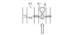
- FIG. 13 is a schematic diagram of the main flow channel h1 and the subflow channel h2 showing a state where water overflowing in the main flow channel h1 stays in the main flow channel h1.
- the gas flowing through the main flow channel h1 where the retained water R is located is located in the secondary flow channel h2.
- the pressure loss of the main flow path h1 due to the staying water R is larger than the total value of the pressure losses in the subflow path h2 that has become a detour. Therefore, there is a problem that the staying water R continues to stay without being swept away by the gas. If the staying water continues to stay as it is, on the downstream side of the main flow path h1 where the staying water R is present, the gas diffusibility deteriorates, the current distribution cannot be made uniform, and the power generation performance deteriorates. become.
- the separators 23 and 24 include a plurality of groove flow paths m extending in the gas flow direction, and the protrusions ma that define the groove flow paths m are in contact with the electrode catalyst layers 17 and 18 of the membrane electrode assembly 15. Are arranged.
- the gas can push the stagnant water R downstream when the fuel cell is under high load.
- the load is low, the accumulated water cannot be swept away by the gas pressure, and the retention is continued. For this reason, the gas diffusibility deteriorates and the current distribution cannot be made uniform, and the power generation performance Will get worse.
- the object of the present invention is to remove stagnant water regardless of high load or low load, improve gas diffusivity and make current distribution uniform, and as a result, improve power generation performance. It is an object to provide a fuel cell capable of performing the above.
- a fuel cell having a plurality of stacked unit cells, each unit cell having a membrane electrode assembly and a membrane electrode assembly interposed therebetween.
- a membrane electrode assembly comprising: a solid polymer electrolyte membrane; and an electrode catalyst layer laminated on each of an anode side surface and a cathode side surface of the solid polymer electrolyte membrane And a gas diffusion layer laminated on the outer surface of each electrode catalyst layer, and a gas flow path forming body is laminated on each outer surface of the gas diffusion layer of each single cell, whereby each single cell Has a gas flow path for fuel gas and a gas flow path for oxidant gas, and at least one of the gas flow path forming bodies of each single cell includes a plurality of gas flow paths and adjacent gas flow paths. Between each gas flow path and it A communication path for guiding water in the gas channel to the water channel is provided between the water channel and the adjacent water channel, and the communication channel has a higher pressure loss
- the communication path guides water in the gas flow path to the water conduit by capillary action. Is done.
- a fuel cell according to the first or second aspect wherein the gas flow path has a groove shape.
- At least one of the gas flow path forming bodies of each single cell is in the gas flow path.
- a communication path is provided at predetermined intervals along the gas flow direction, while on the downstream side of the gas flow direction, a communication path is provided.
- a fuel cell characterized in that the length in the gas flow direction of the portion of the gas flow path forming body not provided with a downstream communication passage in the gas flow direction is larger than the predetermined interval.
- the fuel cell according to any one of the first to third aspects, wherein at least one of the gas flow path forming bodies of each single cell is in the gas flow path.
- the portion on the downstream side of the gas flow direction in which the gas flows is formed flat or lifted so that at least some of the communication paths communicate with each other at a position corresponding to the portion.
- a fuel cell is provided.
- the fuel cell according to the first aspect wherein the gas flow path forming body is provided integrally with the separator, and the gas flow path and the water conduit of each gas flow path forming body. Facing the membrane electrode assembly, a fuel cell is provided.
- the fuel cell according to any one of the first to sixth aspects, wherein the gas flow path and the water conduit of each gas flow path forming body extend linearly.
- a fuel cell is provided in which the communication path guides water in the gas flow path to the water conduit by capillary action.
- gas diffusibility can be improved and current distribution can be made uniform regardless of high load and low load, and as a result, power generation performance can be improved. There is an effect.
- the permeated water touches the communication path, it can flow into the water conduit through the communication path by capillary action. It is possible to suppress the osmotic water from staying in the path.
- the gas channel can be easily formed by forming the gas channel into a groove shape.
- the pressure loss of the water conduit is sufficiently larger than the pressure loss of the gas flow path. It is possible to suppress the gas in the flow path from flowing into the water conduit through the communication path.
- the gas flow path forming body is provided integrally with the separator, and each gas flow path and each water conduit of the gas flow path forming body are formed by the membrane electrode assembly.
- the gas flow path and the water conduit can be easily formed, and the permeated water can be obtained even when the fuel cell has a low load.
- it touches the communication path it can be caused to flow into the water conduit through the communication path by capillary action, so that the permeated water can be suppressed in the gas flow path.
- FIG. 1 is a cross-sectional view of a fuel cell according to an embodiment of the present invention.
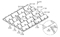
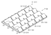
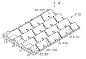
- A is a fragmentary perspective view of the 1st, 2nd gas flow path formation body of the fuel cell of FIG. 1
- (b) is explanatory drawing of the gas flow path and water conduit of the fuel cell of FIG.
- (b) is a schematic diagram of the gas flow path and communication path of the fuel cell of FIG.
- FIG. 12 is a schematic diagram of a main flow channel and a sub flow channel in which stagnant water exists in the fuel battery cell of FIG. 11.
- FIG. 10 is a perspective view in a case where stagnant water is present in a groove channel of a separator in another conventional example.
- the fuel cell 11 of the first embodiment is a solid polymer fuel cell, and has a stack structure including a large number of stacked single cells 12 and a cooling water channel (not shown). ing.
- the single cell 12 includes a membrane electrode assembly 15 (MEA: Membrane-Electrode-Assembly) in first and second frames 13 and 14 made of synthetic resin such as a synthetic rubber having a square frame shape.
- MEA Membrane-Electrode-Assembly
- the first frame 13 defines a fuel gas flow path space 13a inside thereof.
- the second frame 14 defines an oxidant gas flow passage space 14 a inside thereof.
- the membrane electrode assembly 15 is disposed between the frames 13 and 14.
- the single cell 12 includes a first gas flow path forming body 31 made of ferritic SUS (stainless steel), titanium alloy, or carbon housed in the flow path space 13a for the fuel gas, and a flow path space for the oxidant gas. And a second gas flow path forming body 41 made of a ferritic SUS (stainless steel), a titanium alloy, carbon, a titanium alloy plated with gold, or a gold alloy accommodated in 14a. Further, the single cell 12 includes a first separator 23 and a second separator 24 each having a flat plate shape made of ferritic SUS (stainless steel), titanium alloy, or carbon.
- the 1st separator 23 is joined to the upper surface of the 1st flame
- the second separator 24 is joined to the lower surface of the second frame 14 and the second gas flow path forming body 41 via a seal ring (not shown).
- the membrane electrode assembly 15 includes a solid polymer electrolyte membrane 16, a first electrode catalyst layer 17 and a second electrode catalyst layer 18, and a first gas diffusion layer 19 and a second gas diffusion layer 20. .
- the first electrode catalyst layer 17 is formed by laminating a catalyst on the anode side surface of the electrolyte membrane 16, that is, the upper surface in FIG.
- the second electrode catalyst layer 18 is formed by laminating a catalyst on the cathode side surface of the electrolyte membrane 16, that is, the lower surface in FIG.
- the solid polymer electrolyte membrane 16 is made of a solid polymer material having good proton conductivity in a wet state. Such a solid polymer material includes a fluorine-based polymer film (for example, a Nafion film manufactured by DuPont).
- the electrode catalyst layers 17 and 18 include carbon particles (not shown), and a large number of catalyst particles made of platinum (Pt) are attached to the surfaces of the carbon particles.
- the power generation efficiency of the fuel cell can be increased by the catalytic action of the catalyst particles.
- platinum contained in the electrode catalyst layers 17 and 18 has an action of promoting separation of hydrogen into protons and electrons or promoting a reaction of generating water from oxygen, protons, and electrons. As long as it has an effect
- a first gas diffusion layer 19 having conductivity is laminated on the electrode catalyst layer 17 on the anode side.
- a conductive second gas diffusion layer 20 is laminated on the electrode catalyst layer 18 on the cathode side.
- the gas diffusion layers 19 and 20 are usually made of carbon paper or carbon cloth.
- the first gas flow path forming body 31 and the second gas flow path forming body 41 will be described. Since the first gas flow path forming body 31 located on the anode side and the second gas flow path forming body 41 located on the cathode side have the same configuration, the configuration of the first gas flow path forming body 31 Only described below. Of course, both may not have the same configuration.
- the same part as the configuration of the first gas flow path forming body 31 includes each member of the first gas flow path forming body 31.
- the reference numerals obtained by adding 100 to the reference numerals are attached.
- the “first separator 23” is the “second separator 24” and the “gas diffusion layer 19” is the “second gas diffusion layer 20”.
- the “fuel gas flow direction P” should be read as “oxidant gas flow direction Q”, and the reference numerals of the respective members of the first gas flow path forming body 31 should be added by 100.
- the direction in which the fuel gas flows is indicated by an arrow P.
- the surface of the first gas flow path forming body 31 on the gas diffusion layer 19 side (the upper surface in FIG. 2 (a)) has a plurality of groove-like shapes extending linearly.
- a gas flow path 32 is formed.
- a plurality of water conduits 33 extending in a straight line are provided on the surface of the first gas flow path forming body 31 on the first separator 23 side (the lower surface in FIG. 2A).
- the first gas flow path forming body 31 is formed such that a cross-sectional shape cut in a direction orthogonal to the fuel gas flow direction P has a substantially waveform.
- the cross-sectional shape of the 1st gas flow path formation body 31 is not limited to a waveform, For example, a rectangular shape may be sufficient.
- the gas flow path 32 is formed between a plurality of protrusions 34 extending in the fuel gas flow direction P and protruding toward the gas diffusion layer 19.
- the water conduit 33 is formed between a plurality of ridges 35 extending in the fuel gas flow direction P and projecting toward the first separator 23.
- the cross-sectional shape of the first gas flow path forming body 31 is not limited to a sine curve shape, and may be other waveform shapes such as a triangular wave shape and a pulse wave shape.
- the first gas flow path forming body 31 is orthogonal to the fuel gas flow direction P by press-molding the protrusions 34 and 35.
- Ribs 37 are provided at predetermined pitches.
- the rib 37 is formed with a 1 ⁇ 2 pitch shifted from the protrusions 34 and 35 adjacent to each other.
- the rib 37 has a portion (hereinafter referred to as a baffle plate portion 37 a) that bridges the protrusions 35 in the water conduit 33 and a portion 37 b that is disposed in the gas flow path 32.
- the baffle plate portion 37a is located between the tops of the ridges 35 and the length thereof is longer than the length of the portion 37b located on the back side of the ridges 35. It has become.
- the cross-sectional area of the water conduit 33 is narrower than the cross-sectional area of the gas flow path 32. Therefore, since the gas channel 32 has a substantially larger opening cross-sectional area than the water conduit 33 due to the presence of the baffle plate portion 37a, the gas flows mainly through the gas channel 32.
- a passage 38 is formed in the rib 37 in the length direction of the rib 37, and the passage 38 allows water to pass between the adjacent conduits 33. Yes.
- the thickness t2 of the rib 37 portion shown in FIG. is substantially the same as the thickness t1 of the portion of the body 31 forming a substantially waveform, the thicknesses of both are not limited to be substantially the same.
- the top of the protrusion 34 is in contact with the gas diffusion layer 19, and the top of the protrusion 35 is in contact with the first separator 23.
- the single cell 12 positioned at the uppermost end is cut in a cross-section such that the water conduit 33 appears in the figure, whereas the single cell 12 positioned at the lowermost end is a gas
- the channel 32 is cut in a cross section as it appears in the figure.
- a portion corresponding to the baffle plate portion 37 a is perpendicular to the fuel gas flow direction P (that is, the direction in which the gas flow channel 32 extends), and the gas flow channel 32.
- a plurality of communication passages 36 and openings 36a communicating between the water guide passages 33 and the water guide passages 33 are cut and formed by pressing when the ribs 37 are formed (see FIG. 3).
- the communication path 36 and the opening 36a have a cross-sectional shape and an open cross-sectional area in which capillary action works.
- the pressure loss in the communication path 36 is larger than the pressure loss in the gas flow path 32.
- the pressure loss of the gas flow path 32 at the time of drying in which the communication path 36 is not provided and no stagnant water is generated is ⁇ Pd
- the communication path 36 is not provided
- the stagnant water is gas.
- ⁇ Pw be the pressure loss of the gas flow path 32 when staying in the flow path 32.
- the coefficient k is a value larger than 1 (1 ⁇ k), and may be 2 or more.
- the pressure loss of the communication path 36 provided in the gas flow path 32 is assumed to be ⁇ Pi.
- i 1, 2,..., N
- n is a communication path 36 located upstream of the gas flow path from the position where the accumulated water is present when the water flow is present in the gas flow path 32.
- ⁇ Pw k ⁇ ⁇ Pd ⁇ ( ⁇ P1 + ⁇ P2 +... + ⁇ Pn)
- the communication path 36 has a width and a height perpendicular to the width so that a capillary action is exerted (that is, the cross section). (Size of shape) is set, and a cross-sectional area that defines the pressure loss of the gas flow path 32 (that is, a width that determines the cross-sectional area) is set.
- a fuel gas (hydrogen gas) is supplied from a fuel gas supply source (for example, a hydrogen cylinder) (not shown) to the frames 13 and 14 and the separators 23 and 24 of each unit cell 12.
- a fuel gas supply source for example, a hydrogen cylinder
- An introduction passage R ⁇ b> 1 for supplying the gas to the gas generator 32 is formed, and a lead-out passage R ⁇ b> 2 for leading the fuel off gas used for power generation to the outside is formed.
- an oxidant gas (air) is introduced into the oxidant gas flow path 132 from an oxidant gas supply source (for example, a compressor) (not shown) into the frames 13 and 14 and the separators 23 and 24 of the single cell 12.
- the introduction passage M1 is formed, and a lead-out passage M2 for leading the oxidizing off gas used for power generation to the outside is formed.
- fuel (hydrogen) gas is supplied from the introduction passage R1 into the gas flow path 32 of the first gas flow path forming body 31, and the fuel gas flow direction P (the left side of FIG. Direction).
- the fuel gas is uniformly supplied to the first electrode catalyst layer 17 by diffusing and passing through the first gas diffusion layer 19 in the gas flow path 32.
- the oxidant (oxygen) gas supplied by the compressor is supplied to the gas flow path 132 of the second gas flow path forming body 41 through the introduction passage M1, and the inside of the gas flow path 132 is oxidant gas. It flows in the flow direction Q (right direction in FIG. 1).
- the oxidant gas is uniformly supplied to the second electrode catalyst layer 18 by diffusing and passing through the second gas diffusion layer 20 in the gas flow path 132.
- a part of the fuel gas that is not used at the time of power generation passes from the fuel gas flow path 32 of the first gas flow path forming body 31 through the lead-out path R2 as the fuel off gas. It is discharged outside. Oxidant gas that has not been used during power generation is discharged from the gas flow path 132 to the outside through the outlet passage M2 as an oxidizing off gas.
- water is generated in the gas flow path 132 of the second gas flow path forming body 41 on the cathode side by the electrode reaction in the membrane electrode assembly 15 described above.
- a part of the generated water is discharged to the outlet passage R2 by the flow pressure of the oxidant gas flowing in the gas flow path 132 as shown in FIG. That is, when the fuel cell is under a high load, the oxidant gas does not flow through the communication path 136 but flows while pushing out water in the gas flow path 132.
- a part of the water flows into the water conduit 133 via the communication passage 136 and is drained to the outlet passage R2.
- the gas flow becomes weak when the fuel cell is under a low load. In this case, as shown in FIG. Then, the water flows into the water conduit 133 through the communication path 136. For this reason, retention of generated water in the gas flow path 132 is suppressed.
- the permeated water that has flowed into the fuel gas flow path 32 moves into the gas flow path 32 at low load, when the permeated water touches the communication path 36 in the same manner, the capillary action causes the communication gas to pass through the communication path 36. Then, it flows into the water conduit 33. For this reason, the permeated water stays in the gas flow path 32.
- the generated water and the permeated water do not stay in the gas flow paths 32 and 132, so that the gas diffusibility is improved and the electrode reaction in the membrane electrode assembly 15 is made uniform, that is, The current distribution can be made uniform, and as a result, the power generation performance is improved.
- the fuel cell of the present embodiment includes the first separator 23 and the second separator 24 that are provided separately from the first gas flow path forming body 31 and the second gas flow path forming body 41.
- the first gas flow path forming body 31 is provided with water conduits 33 and 133 for draining between adjacent gas flow paths 32 and 132. Between the water conduits 33 and 133 and the gas passages 32 and 132 adjacent thereto, communication passages 36 and 136 for guiding water in the gas passages 32 and 132 to the water conduit are provided.
- the communication paths 36 and 136 have a higher pressure loss than the gas flow paths 32 and 132, respectively.
- the first gas flow path forming body 31 and the second gas flow path forming body 41 are provided separately from the separator.
- the gas flow paths 32 and 132 of the first gas flow path forming body 31 and the second gas flow path forming body 41 face the solid polymer electrolyte membrane 16, and the first gas flow path forming body 31 and
- the water conduits 33 and 133 of the second gas flow path forming body 41 face the first separator 23 and the second separator 24 on the first gas flow path forming body 31 and the second gas flow path forming body 41 side, respectively. ing.
- the effect (1) can be easily realized.
- the communication paths 36 and 136 are formed such that the size of the cross-sectional shape thereof is such that the capillary action works, and the water in the gas flow paths 32 and 132 is communicated by the capillary action. 36, 136.
- the gas flow paths 32 and 132 are groove-shaped, so that the gas flow paths can be easily formed.
- the gas flow paths 32 and 132 and the water conduits 33 and 133 are formed in a straight line, and the size of the cross-sectional shape of the communication paths 36 and 136 is such that the capillary action works.
- the water in the gas flow paths 32 and 132 is guided to the water conduit by the capillary action.
- the gas flow path and the water conduit can be easily formed, and even when the fuel cell has a low load, when the permeated water touches the communication path, capillary action causes the communication path to pass through the communication path. Since it can be made to flow into a water conduit, it can control that permeated water retains in a gas channel.
- first gas flow path forming body 31 and the second gas flow path forming body 41 are provided separately from the first separator 23 and the second separator 24.
- first gas flow path forming body 41 At least one of 31 and the second gas flow path forming body 41 may be provided integrally with the separator.
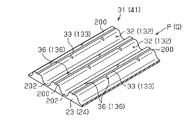
- FIG. 5 shows an example of this.
- a plurality of protrusions 200 having a trapezoidal cross section are provided in parallel to the flat plate-like first separator 23 (second separator 24), and a groove 202 between them is formed.
- This is a gas passage (gas flow paths 32, 132).
- the water guide path 33 (water guide path 133) extended linearly along the fuel gas flow direction P (oxidant gas flow direction Q) is provided in the top part of each protrusion 200, and the water guide path 33 (water guide path 133).
- a communication path 36 (communication path 136) is provided between the gas flow path 32 and the gas flow path 32 (gas flow path 132).
- the communication path 36 (communication path 136) is formed so that a capillary action works.
- FIG. 6 shows another example in which the first gas flow path forming body 31 and the second gas flow path forming body 41 are provided integrally with the first separator 23 and the second separator 24.
- the flat plate material is formed by press molding or the like so that the cross section repeats unevenness, and a plurality of trapezoidal protrusions 200 and a plurality of groove portions 202 are formed in a straight line.
- the groove 202 is a gas flow path 32 (gas flow path 132).
- a water conduit 33 (water conduit 133) is formed along the fuel gas flow direction P (oxidant gas flow direction Q).
- the water conduit 33 (water conduit 133) is provided with a plurality of communication paths 36 (communication paths 136) that open to adjacent gas flow paths 32 (gas flow paths 132).
- the first gas flow path forming body 31 and the second gas flow path forming body 41 are provided integrally with the first separator 23 and the second separator 24, respectively.
- the gas flow paths 32 and 132 and the water conduits 33 and 133 of the first gas flow path forming body 31 and the second gas flow path forming body 41 face the solid polymer electrolyte membrane. There exists an effect similar to said (1) of embodiment.
- water conduit 33 (water conduit 133) does not need to be limited to the arrangement shown in FIGS. 5 and 6, and may be arbitrarily arranged.
- the plurality of groove-like gas flow paths 32 are formed in a straight line and the plurality of water conduits 33 are provided in a straight line on the side surface on the first separator 23 side.
- other shapes such as a curved shape may be used.
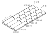
- the gas flow path forming body 31 (41) of the fuel cell 11 of the above embodiment may be replaced with a gas flow path forming body 31 (41) as shown in FIG.
- the fuel gas flow direction P (or oxidant gas flow direction Q) is present in the upstream portion of the fuel gas flow direction P (or oxidant gas flow direction Q).
- a communication path 36 (136) is provided at predetermined intervals along the line, and a communication path 36 (136) is provided in a downstream portion of the fuel gas flow direction P (or oxidant gas flow direction Q).
- the length L of the fuel gas flow direction P (or the oxidant gas flow direction Q) of the portion where the downstream communication passage 36 (136) is not provided in the fuel gas flow direction P (or the oxidant gas flow direction Q) is It is preferable that the size is larger than the predetermined interval. In this case, the fuel gas (or oxidant gas) in the gas flow path 32 (132) can be prevented from flowing into the water conduit 33 (133) through the communication path 36 (136). This is because, since the communication passage 36 (136) is not provided in the downstream portion of the fuel gas flow direction P (or the oxidant gas flow direction Q), even the stagnant water exists in the gas flow path 32 (132).
- the pressure loss of the water conduit 33 (133) is sufficiently larger than the pressure loss of the gas flow channel 32. Since the gas that has flowed into the water conduit 33 (133) is discharged without being used for power generation, it is possible to use gas by suppressing the flow of fuel gas (or oxidant gas) into the water conduit 33 (133). Efficiency can be improved.
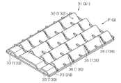
- the gas flow path forming body 31 (41) of the fuel cell 11 of the above embodiment may be replaced with a gas flow path forming body 31 (41) as shown in any of FIGS.
- the portion on the downstream side in the fuel gas flow direction P (or the oxidant gas flow direction Q) is flat, and thus at a position corresponding to the same portion.
- Adjacent water conduits 33 (133) communicate with each other.
- the downstream portion of the fuel gas flow direction P (or the oxidant gas flow direction Q) is partially lifted to correspond to the same portion.
- Some adjacent water conduits 33 (133) communicate with each other at the position.
- the downstream portion of the fuel gas flow direction P (or the oxidant gas flow direction Q) is lifted and formed at a position corresponding to the same portion. All the water conduits 33 (133) are in communication. In these cases, even if there is stagnant water in the gas flow path 32 (132), the pressure loss of the water conduit 33 (133) is sufficiently larger than the pressure loss of the gas flow path 32, so the gas flow path 32 It is possible to suppress the fuel gas (or oxidant gas) (132) from flowing into the water conduit 33 (133) through the communication path 36 (136).
- SYMBOLS 11 Fuel cell, 15 ... Membrane electrode assembly, 16 ... Solid polymer electrolyte membrane, 17 ... 1st electrode catalyst layer, 18 ... 2nd electrode catalyst layer, 23 ... 1st separator, 24 ... 2nd separator, 31 ... 1st gas flow path formation body, 32 ... gas flow path, 33 ... water conduit, 36 ... communication path, 41 ... 2nd gas flow path formation body, 132 ... gas flow path, 133 ... water flow path, 136 ... communication path.
Landscapes
- Life Sciences & Earth Sciences (AREA)
- Engineering & Computer Science (AREA)
- Manufacturing & Machinery (AREA)
- Sustainable Development (AREA)
- Sustainable Energy (AREA)
- Chemical & Material Sciences (AREA)
- Chemical Kinetics & Catalysis (AREA)
- Electrochemistry (AREA)
- General Chemical & Material Sciences (AREA)
- Fuel Cell (AREA)
Description
以下、本発明の燃料電池を具体化した第1実施形態について図1~図4(b)を参照して説明する。
ΔPw=k・ΔPd<(ΔP1+ΔP2+…+ΔPn)
とする。
さて、上記のように構成された燃料電池の作用を説明する。
Claims (7)
- スタックされた複数の単セルを有する燃料電池であって、各単セルは、膜電極接合体と、膜電極接合体を間に挟んで配置される一対のセパレータとを備え、前記膜電極接合体は、固体高分子電解質膜と、固体高分子電解質膜のアノード側の面及びカソード側の面にそれぞれ積層された電極触媒層と、各電極触媒層の外側面に積層されたガス拡散層とを備え、各単セルのガス拡散層のそれぞれの外側面にはガス流路形成体が積層されていて、これにより各単セルは燃料ガス用のガス流路及び酸化剤ガス用のガス流路を有しており、
各単セルのガス流路形成体のうち少なくとも一方は、複数のガス流路と、隣接するガス流路の間にそれぞれ位置する導水路とを備え、各ガス流路とそれに隣接する導水路との間には、ガス流路内の水を導水路に導くための連通路が設けられており、その連通路がガス流路に比べて高い圧力損失を有することを特徴とする燃料電池。 - 前記連通路は、毛管作用により前記ガス流路内の水を前記導水路に導くことを特徴とする請求項1に記載の燃料電池。
- 前記ガス流路は溝状であることを特徴とする請求項1又は請求項2に記載の燃料電池。
- 各単セルのガス流路形成体のうち少なくとも一方は、ガス流路内をガスが流れる方向であるガス流方向の上流側の部分にはガス流方向に沿って所定間隔ごとに連通路が設けられている一方、ガス流方向の下流側の部分には連通路が設けられておらず、ガス流方向の下流側の連通路が設けられていないガス流路形成体の部分のガス流方向の長さは前記所定間隔の大きさよりも大きいことを特徴とする請求項1乃至請求項3のうちいずれか1項に記載の燃料電池。
- 各単セルのガス流路形成体のうち少なくとも一方は、ガス流路内をガスが流れる方向であるガス流方向の下流側の部分が平坦に形成されるか或いは持ち上げて形成されることにより、同部分に対応する位置で少なくとも一部の連通路が互いに連通していることを特徴とする請求項1乃至請求項3のうちいずれか1項に記載の燃料電池。
- 前記ガス流路形成体は、前記セパレータとそれぞれ一体に設けられ、
各ガス流路形成体のガス流路及び導水路は、前記膜電極接合体に面していることを特徴とする請求項1に記載の燃料電池。 - 各ガス流路形成体のガス流路及び導水路は直線状に延びており、前記連通路は、毛管作用により前記ガス流路内の水を前記導水路に導くことを特徴とする請求項1乃至請求項6のうちいずれか1項に記載の燃料電池。
Priority Applications (3)
| Application Number | Priority Date | Filing Date | Title |
|---|---|---|---|
| JP2014525728A JP6036825B2 (ja) | 2012-07-17 | 2013-03-01 | 燃料電池 |
| EP13820402.9A EP2876715B1 (en) | 2012-07-17 | 2013-03-01 | Fuel cell |
| US14/410,465 US10727511B2 (en) | 2012-07-17 | 2013-03-01 | Fuel cell |
Applications Claiming Priority (2)
| Application Number | Priority Date | Filing Date | Title |
|---|---|---|---|
| JP2012158737 | 2012-07-17 | ||
| JP2012-158737 | 2012-07-17 |
Publications (1)
| Publication Number | Publication Date |
|---|---|
| WO2014013747A1 true WO2014013747A1 (ja) | 2014-01-23 |
Family
ID=49948584
Family Applications (1)
| Application Number | Title | Priority Date | Filing Date |
|---|---|---|---|
| PCT/JP2013/055718 Ceased WO2014013747A1 (ja) | 2012-07-17 | 2013-03-01 | 燃料電池 |
Country Status (4)
| Country | Link |
|---|---|
| US (1) | US10727511B2 (ja) |
| EP (1) | EP2876715B1 (ja) |
| JP (1) | JP6036825B2 (ja) |
| WO (1) | WO2014013747A1 (ja) |
Cited By (9)
| Publication number | Priority date | Publication date | Assignee | Title |
|---|---|---|---|---|
| CN105226304A (zh) * | 2014-06-12 | 2016-01-06 | 现代自动车株式会社 | 燃料电池 |
| EP3021394A4 (en) * | 2013-07-08 | 2017-03-15 | Toyota Shatai Kabushiki Kaisha | Gas channel forming member for fuel cells, and fuel cell |
| JP2017191687A (ja) * | 2016-04-12 | 2017-10-19 | トヨタ自動車株式会社 | 燃料電池 |
| JP2017201617A (ja) * | 2016-04-27 | 2017-11-09 | トヨタ車体株式会社 | 燃料電池用ガス流路形成板および燃料電池スタック |
| JP2018026330A (ja) * | 2016-07-28 | 2018-02-15 | トヨタ自動車株式会社 | ガス流路形成部材 |
| JP2018536262A (ja) * | 2015-12-17 | 2018-12-06 | バイエリッシェ モトーレン ヴェルケ アクチエンゲゼルシャフトBayerische Motoren Werke Aktiengesellschaft | バイポーラプレートを製造する方法 |
| JP2019526148A (ja) * | 2016-07-25 | 2019-09-12 | エルジー・ケム・リミテッド | 分離板、およびこれを含む燃料電池スタック |
| JP2020047443A (ja) * | 2018-09-18 | 2020-03-26 | トヨタ自動車株式会社 | 燃料電池 |
| JP2023547131A (ja) * | 2020-10-29 | 2023-11-09 | ロベルト・ボッシュ・ゲゼルシャフト・ミト・ベシュレンクテル・ハフツング | 電気化学セルのための分配プレート、および電気化学セル |
Families Citing this family (7)
| Publication number | Priority date | Publication date | Assignee | Title |
|---|---|---|---|---|
| WO2018222265A1 (en) * | 2017-05-31 | 2018-12-06 | Fuelcell Energy, Inc. | Fuel cell anode flow field design configurations for achieving increased fuel utilization |
| CN107611457B (zh) * | 2017-08-31 | 2020-09-29 | 上海汽车集团股份有限公司 | 一种燃料电池及其阴极板 |
| JP6897471B2 (ja) * | 2017-10-04 | 2021-06-30 | トヨタ車体株式会社 | 燃料電池用ガス流路形成板および燃料電池スタック |
| CN110854402A (zh) * | 2018-08-21 | 2020-02-28 | 上海汽车集团股份有限公司 | 一种气体扩散层前驱体及其制备方法以及气体扩散层和燃料电池 |
| JP7136030B2 (ja) * | 2019-07-19 | 2022-09-13 | トヨタ車体株式会社 | 燃料電池スタック |
| JP7192759B2 (ja) * | 2019-12-24 | 2022-12-20 | トヨタ車体株式会社 | 燃料電池用セパレータ |
| DE102020213591A1 (de) * | 2020-10-29 | 2022-05-05 | Robert Bosch Gesellschaft mit beschränkter Haftung | Verteilerplatte für eine elektrochemische Zelle, Verfahren zur Herstellung der Verteilerplatte und elektrochemische Zelle sowie ein Verfahren zum Betrieb der elektrochemischen Zelle |
Citations (6)
| Publication number | Priority date | Publication date | Assignee | Title |
|---|---|---|---|---|
| JPH06231793A (ja) * | 1993-02-04 | 1994-08-19 | Mitsubishi Heavy Ind Ltd | 固体高分子電解質型燃料電池 |
| JP2002530816A (ja) * | 1998-11-12 | 2002-09-17 | コミツサリア タ レネルジー アトミーク | 燃料電池のためのバイポーラプレートおよびこのようなプレートを具備した燃料電池 |
| JP2008293728A (ja) * | 2007-05-23 | 2008-12-04 | Toyota Motor Corp | ガス流路構成部材 |
| JP2009048775A (ja) * | 2007-08-13 | 2009-03-05 | Nissan Motor Co Ltd | 燃料電池 |
| JP2009087844A (ja) * | 2007-10-02 | 2009-04-23 | Nissan Motor Co Ltd | 燃料電池の発電セル構造及び発電セルの湿潤調整方法 |
| JP2011150801A (ja) | 2010-01-19 | 2011-08-04 | Toyota Auto Body Co Ltd | 燃料電池 |
Family Cites Families (13)
| Publication number | Priority date | Publication date | Assignee | Title |
|---|---|---|---|---|
| JPS61279068A (ja) * | 1985-06-05 | 1986-12-09 | Ishikawajima Harima Heavy Ind Co Ltd | 溶融炭酸塩燃料電池 |
| JPH0746613B2 (ja) * | 1986-08-29 | 1995-05-17 | 株式会社日立製作所 | 燃料電池のガス流路 |
| JP3331117B2 (ja) * | 1996-04-18 | 2002-10-07 | 三菱電機株式会社 | 燃料電池、燃料電池の製造方法、複合ガスセパレータ、およびその製造方法 |
| JP4019554B2 (ja) * | 1998-08-03 | 2007-12-12 | トヨタ自動車株式会社 | 燃料電池セパレータ用多連凹凸板の製造方法 |
| JP2004103455A (ja) | 2002-09-11 | 2004-04-02 | Nissan Motor Co Ltd | 固体高分子型燃料電池およびその運転方法 |
| JP2005038738A (ja) | 2003-07-16 | 2005-02-10 | Mitsubishi Rayon Co Ltd | ガス拡散層電極基材及びその製造方法ならびに高分子電解質型燃料電池 |
| JP4992188B2 (ja) | 2005-03-11 | 2012-08-08 | 株式会社エクォス・リサーチ | セパレータユニット及び燃料電池スタック |
| US8546045B2 (en) * | 2005-09-19 | 2013-10-01 | 3M Innovative Properties Company | Gasketed subassembly for use in fuel cells including replicated structures |
| JP2007294340A (ja) | 2006-04-27 | 2007-11-08 | Honda Motor Co Ltd | 燃料電池 |
| JP2008287945A (ja) | 2007-05-15 | 2008-11-27 | Toyota Motor Corp | 燃料電池のガス流路形成部材および燃料電池 |
| CN102227838B (zh) * | 2008-11-28 | 2014-03-12 | 日产自动车株式会社 | 固体高分子型燃料电池 |
| WO2010113252A1 (ja) | 2009-03-31 | 2010-10-07 | トヨタ車体 株式会社 | 燃料電池 |
| US20130177827A1 (en) | 2010-09-16 | 2013-07-11 | Toyota Jidosha Kabushiki Kaisha | Separator for fuel cell, fuel cell and method of manufacturing fuel cell |
-
2013
- 2013-03-01 JP JP2014525728A patent/JP6036825B2/ja active Active
- 2013-03-01 EP EP13820402.9A patent/EP2876715B1/en active Active
- 2013-03-01 WO PCT/JP2013/055718 patent/WO2014013747A1/ja not_active Ceased
- 2013-03-01 US US14/410,465 patent/US10727511B2/en active Active
Patent Citations (6)
| Publication number | Priority date | Publication date | Assignee | Title |
|---|---|---|---|---|
| JPH06231793A (ja) * | 1993-02-04 | 1994-08-19 | Mitsubishi Heavy Ind Ltd | 固体高分子電解質型燃料電池 |
| JP2002530816A (ja) * | 1998-11-12 | 2002-09-17 | コミツサリア タ レネルジー アトミーク | 燃料電池のためのバイポーラプレートおよびこのようなプレートを具備した燃料電池 |
| JP2008293728A (ja) * | 2007-05-23 | 2008-12-04 | Toyota Motor Corp | ガス流路構成部材 |
| JP2009048775A (ja) * | 2007-08-13 | 2009-03-05 | Nissan Motor Co Ltd | 燃料電池 |
| JP2009087844A (ja) * | 2007-10-02 | 2009-04-23 | Nissan Motor Co Ltd | 燃料電池の発電セル構造及び発電セルの湿潤調整方法 |
| JP2011150801A (ja) | 2010-01-19 | 2011-08-04 | Toyota Auto Body Co Ltd | 燃料電池 |
Cited By (14)
| Publication number | Priority date | Publication date | Assignee | Title |
|---|---|---|---|---|
| US9960433B2 (en) | 2013-07-08 | 2018-05-01 | Toyota Shatai Kabushiki Kaisha | Gas channel forming member for fuel cells, and fuel cell |
| EP3021394A4 (en) * | 2013-07-08 | 2017-03-15 | Toyota Shatai Kabushiki Kaisha | Gas channel forming member for fuel cells, and fuel cell |
| JP2016004778A (ja) * | 2014-06-12 | 2016-01-12 | 現代自動車株式会社Hyundaimotor Company | 燃料電池 |
| CN105226304A (zh) * | 2014-06-12 | 2016-01-06 | 现代自动车株式会社 | 燃料电池 |
| US11456465B2 (en) | 2015-12-17 | 2022-09-27 | Bayerische Motoren Werke Aktiengesellschaft | Method for producing a bipolar plate |
| JP2018536262A (ja) * | 2015-12-17 | 2018-12-06 | バイエリッシェ モトーレン ヴェルケ アクチエンゲゼルシャフトBayerische Motoren Werke Aktiengesellschaft | バイポーラプレートを製造する方法 |
| JP2017191687A (ja) * | 2016-04-12 | 2017-10-19 | トヨタ自動車株式会社 | 燃料電池 |
| JP2017201617A (ja) * | 2016-04-27 | 2017-11-09 | トヨタ車体株式会社 | 燃料電池用ガス流路形成板および燃料電池スタック |
| JP2019526148A (ja) * | 2016-07-25 | 2019-09-12 | エルジー・ケム・リミテッド | 分離板、およびこれを含む燃料電池スタック |
| JP2018026330A (ja) * | 2016-07-28 | 2018-02-15 | トヨタ自動車株式会社 | ガス流路形成部材 |
| JP2020047443A (ja) * | 2018-09-18 | 2020-03-26 | トヨタ自動車株式会社 | 燃料電池 |
| JP2023547131A (ja) * | 2020-10-29 | 2023-11-09 | ロベルト・ボッシュ・ゲゼルシャフト・ミト・ベシュレンクテル・ハフツング | 電気化学セルのための分配プレート、および電気化学セル |
| JP7618797B2 (ja) | 2020-10-29 | 2025-01-21 | ロベルト・ボッシュ・ゲゼルシャフト・ミト・ベシュレンクテル・ハフツング | 電気化学セルのための分配プレート、および電気化学セル |
| US12580207B2 (en) | 2020-10-29 | 2026-03-17 | Robert Bosch Gmbh | Distributor plate for an electrochemical cell, and electrochemical cell |
Also Published As
| Publication number | Publication date |
|---|---|
| EP2876715A4 (en) | 2016-03-09 |
| US10727511B2 (en) | 2020-07-28 |
| EP2876715B1 (en) | 2020-05-06 |
| US20150333357A1 (en) | 2015-11-19 |
| JPWO2014013747A1 (ja) | 2016-06-30 |
| EP2876715A1 (en) | 2015-05-27 |
| JP6036825B2 (ja) | 2016-12-07 |
Similar Documents
| Publication | Publication Date | Title |
|---|---|---|
| JP6036825B2 (ja) | 燃料電池 | |
| JP6079303B2 (ja) | 燃料電池のガス流路形成体及び燃料電池 | |
| JP6079304B2 (ja) | 燃料電池のガス流路形成体及び燃料電池 | |
| JP5678276B2 (ja) | 燃料電池 | |
| JP5648293B2 (ja) | 燃料電池 | |
| JP2020107397A (ja) | 燃料電池セル | |
| KR20230129263A (ko) | 가스 확산층, 세퍼레이터 및 전기 화학 반응 장치 | |
| JP5321086B2 (ja) | 燃料電池 | |
| JPWO2011059087A1 (ja) | 燃料電池及び燃料電池を備えた車両 | |
| JP6117736B2 (ja) | 燃料電池 | |
| JP5274908B2 (ja) | 燃料電池スタック | |
| JP2008311047A (ja) | 燃料電池 | |
| JP4572252B2 (ja) | 燃料電池スタック | |
| JP5653867B2 (ja) | 燃料電池 | |
| JP2009099262A (ja) | 燃料電池 | |
| JP5123824B2 (ja) | 燃料電池スタックおよび燃料電池スタックの運転方法 | |
| JP5115070B2 (ja) | 燃料電池 | |
| JP2010153157A (ja) | 燃料電池セパレータ | |
| JP2023102600A (ja) | 発電セル | |
| JP2008277041A (ja) | 燃料電池および燃料電池用ガスセパレータ | |
| JP2023077628A (ja) | 燃料電池 | |
| JP2013257949A (ja) | 燃料電池 | |
| JPWO2010067452A1 (ja) | 燃料電池 | |
| JP2018125259A (ja) | 燃料電池 | |
| JP2010140792A (ja) | 燃料電池 |
Legal Events
| Date | Code | Title | Description |
|---|---|---|---|
| 121 | Ep: the epo has been informed by wipo that ep was designated in this application |
Ref document number: 13820402 Country of ref document: EP Kind code of ref document: A1 |
|
| DPE1 | Request for preliminary examination filed after expiration of 19th month from priority date (pct application filed from 20040101) | ||
| ENP | Entry into the national phase |
Ref document number: 2014525728 Country of ref document: JP Kind code of ref document: A |
|
| WWE | Wipo information: entry into national phase |
Ref document number: 2013820402 Country of ref document: EP |
|
| WWE | Wipo information: entry into national phase |
Ref document number: 14410465 Country of ref document: US |
|
| NENP | Non-entry into the national phase |
Ref country code: DE |