WO2014013818A1 - Rfidリストバンド - Google Patents
Rfidリストバンド Download PDFInfo
- Publication number
- WO2014013818A1 WO2014013818A1 PCT/JP2013/066157 JP2013066157W WO2014013818A1 WO 2014013818 A1 WO2014013818 A1 WO 2014013818A1 JP 2013066157 W JP2013066157 W JP 2013066157W WO 2014013818 A1 WO2014013818 A1 WO 2014013818A1
- Authority
- WO
- WIPO (PCT)
- Prior art keywords
- inlay
- rfid wristband
- storage portion
- wall
- elastic block
- Prior art date
- Legal status (The legal status is an assumption and is not a legal conclusion. Google has not performed a legal analysis and makes no representation as to the accuracy of the status listed.)
- Ceased
Links
Images





Classifications
-
- G—PHYSICS
- G06—COMPUTING OR CALCULATING; COUNTING
- G06K—GRAPHICAL DATA READING; PRESENTATION OF DATA; RECORD CARRIERS; HANDLING RECORD CARRIERS
- G06K19/00—Record carriers for use with machines and with at least a part designed to carry digital markings
- G06K19/06—Record carriers for use with machines and with at least a part designed to carry digital markings characterised by the kind of the digital marking, e.g. shape, nature, code
- G06K19/067—Record carriers with conductive marks, printed circuits or semiconductor circuit elements, e.g. credit or identity cards also with resonating or responding marks without active components
- G06K19/07—Record carriers with conductive marks, printed circuits or semiconductor circuit elements, e.g. credit or identity cards also with resonating or responding marks without active components with integrated circuit chips
- G06K19/077—Constructional details, e.g. mounting of circuits in the carrier
- G06K19/07749—Constructional details, e.g. mounting of circuits in the carrier the record carrier being capable of non-contact communication, e.g. constructional details of the antenna of a non-contact smart card
- G06K19/07758—Constructional details, e.g. mounting of circuits in the carrier the record carrier being capable of non-contact communication, e.g. constructional details of the antenna of a non-contact smart card arrangements for adhering the record carrier to further objects or living beings, functioning as an identification tag
- G06K19/07762—Constructional details, e.g. mounting of circuits in the carrier the record carrier being capable of non-contact communication, e.g. constructional details of the antenna of a non-contact smart card arrangements for adhering the record carrier to further objects or living beings, functioning as an identification tag the adhering arrangement making the record carrier wearable, e.g. having the form of a ring, watch, glove or bracelet
-
- A—HUMAN NECESSITIES
- A44—HABERDASHERY; JEWELLERY
- A44C—PERSONAL ADORNMENTS, e.g. JEWELLERY; COINS
- A44C5/00—Bracelets; Wrist-watch straps; Fastenings for bracelets or wrist-watch straps
- A44C5/0007—Bracelets specially adapted for other functions or with means for attaching other articles
- A44C5/0015—Bracelets specially adapted for other functions or with means for attaching other articles providing information, e.g. bracelets with calendars
-
- A—HUMAN NECESSITIES
- A44—HABERDASHERY; JEWELLERY
- A44C—PERSONAL ADORNMENTS, e.g. JEWELLERY; COINS
- A44C5/00—Bracelets; Wrist-watch straps; Fastenings for bracelets or wrist-watch straps
- A44C5/0053—Flexible straps
Definitions
- the present invention relates to an RFID (Radio Frequency Identification; wireless automatic recognition) wristband that is used by being wrapped around a wrist or ankle of a human body, and in particular, an RFID wristband with a built-in non-contact data read / write inlay. About.
- RFID Radio Frequency Identification; wireless automatic recognition
- the inlay 1 includes an IC chip 12 that stores data on one side or both sides of a base substrate 11, and an antenna 13 that is connected to the IC chip 12 and transmits and receives information. ing.
- the antenna 13 is electrically connected to the electrode 12a of the IC chip 12.
- Patent Document 1 discloses a wristband provided with a base material made of polyethylene or a copolymer thereof and a non-contact RFID. However, a wristband made of stretchable silicone rubber is required from the viewpoint of durability due to long-term use. *
- Patent Document 2 discloses a silicone rubber wristband having a recess. In the case of this wristband, the inlay is sealed in the recess with an adhesive.
- Patent Document 3 discloses an RFID wristband made of silicone rubber including an inlay laminated with a hard film. *
- the adhesive and the hard film have low flexibility and stretchability, the followability to deformation and elongation of the silicone rubber is poor.
- the joint portion between the IC chip and the antenna cannot withstand the stress caused by the bending action and the wire breaks. . That is, when stress due to a bending action is applied to the inlay 1, the IC chip 12 may break or break, or the electrode 12 a that bonds the IC chip 12 and the antenna 13 may be peeled or separated. (See FIG. 13A and FIG. 13B).
- the inlay is laminated with a hard film or sealed with an adhesive, the production man-hours increase, and there is a problem that extra materials are required.
- the present invention has been made in view of the above problems, and even when subjected to external impact, pulling or bending, the IC chip breaks or breaks, or an electrode for bonding the IC chip and the antenna is provided. It is an object to provide an RFID wristband that does not peel or separate. Also, an object of the present invention is to provide an RFID wristband that secures a degree of freedom in which the inlay can be moved by giving a margin to a storage portion that stores the inlay. Furthermore, it is an object of the present invention to provide an RFID wristband that is curved along the wrist or ankle when worn on the wrist or ankle, but does not place a load on the inlay itself stored in the storage unit. Furthermore, an object of the present invention is to provide an RFID wristband that can reduce the labor of the production process and reduce the material.
- the present invention relates to an elastic block portion having an airtight storage portion, an elastic band portion that forms a ring by being connected to the elastic block portion, and a base substrate and the base base that are stored in the storage portion.
- An RFID wristband comprising an antenna on a material and an inlay having an IC chip electrically connected to the antenna, wherein the inlay is not fixed to the inner wall of the storage portion, and the storage portion is The RFID wristband is larger than a volume occupied by the inlay.
- at least a part of the inner wall of the storage portion that is in contact with the inlay is formed of an uneven surface.
- an elastic block portion having an airtight storage portion, an elastic band portion constituting an annular shape by being connected to the elastic block portion, a base base material and the base stored in the storage portion
- An RFID wristband comprising an antenna on a substrate and an IC chip electrically connected to the antenna, wherein a part of the inlay is fixed to an inner wall of the storage unit, and
- the storage unit is an RFID wristband characterized by being larger than the volume occupied by the inlay.
- the inlay is fixed to the inner wall of the storage portion by a spot fastening portion formed in a part of the inlay.
- a part of the inlay is fixed by a raised portion formed on the inner wall of the storage portion.
- the inlay is fitted by at least one mounting groove formed on the inner wall of the storage portion.
- the inlay has a through hole, and the through hole is axially passed through a support column formed on the inner wall of the housing portion.
- the inlay may not be laminated with a film.
- the elastic block portion and the elastic band portion may have different colors.
- the elastic block portion and the elastic band portion may have different hardnesses.
- the elastic block portion and the elastic band portion are made of a silicone resin.
- the IC chip breaks or breaks, or the electrode that bonds the IC chip and the antenna peels off. Since separation can be prevented, durability can be improved and stable communication performance can be obtained.
- FIG. 3A is a schematic configuration diagram of an inlay.
- FIG. 3B is an enlarged cross-sectional view of the main part of the IC chip mounting portion of the inlay.
- the principal part expanded sectional view of the RFID wristband in 2nd Embodiment.
- the principal part expanded sectional view of the RFID wristband in 3rd Embodiment.
- the principal part expanded sectional view of the RFID wristband in 4th Embodiment.
- FIG. 12B is a partial perspective view of the sixth embodiment.
- FIG. 13A is an enlarged view of the IC chip mounting portion of the inlay.
- FIG. 13B is an enlarged view showing a damaged state of the IC chip mounting portion of the inlay.
- FIG. 1 is a perspective view of an RFID wristband.
- FIG. 2 is a cross-sectional view of the RFID wristband along the circumferential direction.
- the RFID wristband 30 includes an elastic block portion 33 and an elastic band portion 34 that is connected to both ends of the elastic block portion 33 and has an annular shape.
- the elastic block portion 33 has a storage portion 31 for storing the inlay 1 therein. *
- the storage part 31 is an airtight space formed by being surrounded by a plurality of inner walls 36 constituted by a part of the elastic block part 33 or the elastic band part 34.
- the storage portion 31 is formed larger than the volume (bulk) occupied by the inlay 1. Details of the storage unit 31 will be described in first to sixth embodiments to be described later. *
- the elastic block portion 33 and the elastic band portion 34 are made of an elastic member, they can be easily extended and can be comfortably fitted to the wrist, ankle or the like.
- a material constituting the elastic member for example, thermosetting urethane rubber, thermosetting silicone rubber, or the like can be used.
- thermoplastic elastomers such as styrene-based thermoplastic elastomers, olefin-based thermoplastic elastomers, urethane-based thermoplastic elastomers, polyester-based thermoplastic elastomers, polyamide-based thermoplastic elastomers, and fluorine-based thermoplastic elastomers can be used.
- a thermosetting silicone rubber that is excellent in weather resistance, heat resistance, chemical resistance, flexibility, and the like and has a low relative dielectric constant is preferable.
- the hardness of the elastic block portion 33 and the elastic band portion 34 can be appropriately selected.
- the hardness of the elastic block portion 33 and the elastic band portion 34 can be the same or different.
- the elastic block portion 33 has a high rubber hardness and the elastic band portion 34 has a low rubber hardness, so that when the elastic band portion 34 is stretched, the elastic block portion 33 can be reduced in elasticity when attached to the wrist. it can. *
- the elastic block portion 33 and the elastic band portion 34 can optionally contain a colorant such as a known inorganic pigment, organic pigment, dye or the like.
- a colorant such as a known inorganic pigment, organic pigment, dye or the like.
- a black pigment such as carbon black
- a white pigment such as titanium oxide
- the elastic block portion 33 and the elastic band portion 34 are formed. Can be distinguished.
- the elastic block portion 33 on which the inlay 1 is mounted can be easily seen in the RFID wristband 30, and the elastic block portion 33 on which the inlay 1 is mounted is surely brought close to the reader / writer (not shown), Data can be read easily.
- the antibacterial property can be imparted by including an antibacterial agent in the elastic block portion 33 and the elastic band portion 34.
- Antibacterial agents include silver antibacterial agents such as silica gel silver, silver zeolite and calcium phosphate silver, zinc oxide antibacterial agents, benzimidazole antibacterial agents, triazine antibacterial agents, pyrithione antibacterial agents, nitrile antibacterial agents, and organic iodine type Antibacterial agents and the like can be used.
- FIG. 3A is a schematic configuration diagram of an inlay built in the RFID wristband.
- FIG. 3B is an enlarged cross-sectional view of the main part of the IC chip mounting portion of the inlay.
- 3 (a) and 3 (b) are given the same reference numerals because they have the same configuration as FIGS. 13 (a) and 13 (b).
- the inlay 1 is a non-contact IC circuit capable of non-contact communication with a reader / writer.
- the inlay 1 is connected to the IC chip 12 with an IC chip 12 for storing data on one side or both sides of the base substrate 11.
- an antenna 13 for transmitting and receiving information.
- the antenna 13 is electrically connected to the electrode 12a of the IC chip 12.
- the inlay 1 is often wavy or curved because the base substrate 11 itself is a thin material. *
- the inlay 1 is, for example, a UHF band (300 MHz to 3 GHz (preferably 860 to 960 MHz, more specifically 433 MHz, 900 MHz, 915 to 928 MHz, 950 to 958 MHz) or microwave (1 to 30 GHz, specifically 2 .45 GHz), HF band (3 MHz to 30 MHz (preferably 13.56 MHz)), 135 kHz or less, and other data necessary for the IC chip 12 through the antenna 13 by radio waves and electromagnetic action in a predetermined frequency band.
- the inlay 1 has a specific configuration of the IC chip 12 and the antenna 13 appropriate for each radio wave used.
- polyesters such as polyethylene terephthalate, polyethylene naphthalate, polybutylene terephthalate, polyethylene terephthalate / isophthalate copolymer, polyolefin resins such as polyethylene and polypropylene, and polyfluoride.
- Polyfluorinated ethylene resins such as vinyl fluoride, polyvinylidene fluoride, polytetrafluoroethylene, ethylene-tetrafluoroethylene copolymer, polyamides such as nylon 6 and nylon 66, polyvinyl chloride, vinyl chloride / vinyl acetate copolymer Polymer, vinyl resin such as ethylene / vinyl acetate copolymer, ethylene / vinyl alcohol copolymer, cellulose resin such as cellulose triacetate, cellophane, polymethyl methacrylate, polyethyl methacrylate, poly Ethyl acrylic acid, acrylic resins such as polybutyl acrylate, can be used polystyrene, polycarbonate, a single or a mixture of polyimide or the like can be used as long as it is an organic material of the insulating properties. *
- the antenna 13 is made of, for example, a conductive foil such as a copper foil or an aluminum foil.
- An antenna 13 composed of a conductive foil can be obtained by forming a conductive foil such as a copper foil or an aluminum foil on the base substrate 11 and etching the conductive foil.
- the antenna 13 made of the conductive ink can be obtained by printing the conductive ink on the base substrate 11. Note that one or both sides of the inlay 1 may be laminated with a film. When the inlay 1 is not laminated with a film, the labor of the production process can be reduced and the material can be reduced. *
- FIG. 4 is an enlarged cross-sectional view of the main part of the IC chip mounting portion of the inlay 1 according to another embodiment, and the covering portion 16 is formed on the IC chip 6 portion of the inlay 1 by potting.
- the coating portion 16 is formed by coating a thermal reaction curable liquid resin such as an ultraviolet curable resin or an epoxy resin, or a two-component mixed reaction curable liquid resin, and then curing the resin.
- thermoplastic fibers and thermosetting resins include glass fibers, carbon fibers, aramid fibers, ceramic fibers (silicon carbide, boron, alumina), whiskers (Al 2 O 3 , ⁇ -SiC, graphite, potassium titanate, poly What contains oxymethylene) etc. can be used.
- an epoxy resin containing glass fiber is particularly preferable. Since the covering portion 16 can protect the IC chip 12 and the electrode 12a for bonding the IC chip 12 and the antenna 13, the impact resistance can be further improved.
- FIG. 5 is an enlarged cross-sectional view of a main part of an RFID wristband showing the first embodiment.
- the inlay 1 is stored in a storage portion 31 that is larger than the volume occupied by the inlay 1, but is arranged in a state where it is not fixed to any inner wall 36. Even if the elastic block portion 33 receives an impact from the outside and the internal storage portion 31 is greatly deformed or twisted, the inlay 1 can be freely moved inside the storage portion 31 and is directly stressed. Therefore, the IC chip 12 can be prevented from being broken and broken, and the electrode 12a that bonds the IC chip 12 and the antenna 13 can be prevented from peeling or separating. Further, since the storage portion 31 is kept airtight, the inlay 1 does not become incapable of communication due to water immersion or the like, so that the highly durable RFID wristband 30 can be formed. *
- the RFID wristband 30 is created as follows. As shown in FIG. 6 (a), an elastic member such as a thermosetting silicone rubber is disposed in the recess of the lower mold (not shown), the upper mold (not shown) is pressed against the lower mold, and heated. By pressing, the elastic block portion 33 having the insertion hole 46 is formed (primary molding, semi-vulcanized state). As shown in FIG. 6B, the inlay 1 is inserted into the insertion hole 46 of the elastic block portion 33. As shown in FIG. 6 (c), the elastic block portion 33 and the elastic band are formed by disposing an elastic member for the elastic band portion 34 on both ends of the elastic block portion 33 formed by primary molding and applying heat and pressure.
- an elastic member such as a thermosetting silicone rubber
- the part 34 is welded and formed into an annular shape (secondary molding, vulcanized state).
- the elastic band portion 34 is welded so as to completely close the through hole 46 of the elastic block portion 33, the sealed storage portion 31 can be formed in the elastic block portion 33.
- FIG. 7 is a principal part expanded sectional view of the RFID wristband which shows 2nd Embodiment.
- the inlay 1 is arranged in a state where it is not fixed to any inner wall 36 of the storage portion 31.
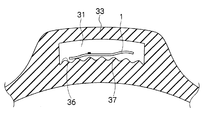
- At least a part of the inner wall 36 of the storage portion 31 that is in contact with the inlay 1 is constituted by an uneven surface 37.
- the difference between the top and bottom of the uneven surface 37 is preferably 0.1 mm to 2.0 mm. If it is less than 0.1 mm, it does not function as the concavo-convex surface 37, and if it is greater than 2.0 mm, the electrode 12 a that adheres the IC chip 12 and the antenna 13 may be peeled or separated by the convex portion of the concavo-convex surface 37 when bent. *
- FIG. 8 is a principal part expanded sectional view of the RFID wristband which shows 3rd Embodiment.
- the spot fastening portion 40 is formed on a part of the inlay 1. This dot fastening portion 40 is a very small portion of the inlay 1.
- the spot-fastening portion 40 is formed by a known heat fusion means such as heat fusion bonding, heat sealing, high frequency welder fusion, or ultrasonic welder fusion. *
- the inlay 1 does not move too much in the storage portion 31. Even if it receives bending or impact from the outside, the degree of freedom that the inlay 1 can move inside the storage portion 31 is secured, so that the IC chip 12 is not damaged without being directly stressed. it can. Further, even if the elastic band portion 33 expands or contracts or curves, and the storage portion 31 is greatly deformed or twisted, the inner wall 36 and the inlay 1 of the storage portion 31 are deformed separately, so that the IC chip It is possible to prevent the electrode 12a that bonds the antenna 12 and the antenna 13 from peeling or separating. *
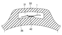
- FIG. 9 is a principal part expanded sectional view of the RFID wristband which shows 4th Embodiment.
- the inlay 1 is disposed in the storage portion 31 in a state in which a part of the inlay 1 is fixed to the raised portion 42 formed on the inner wall 36 of the storage portion 31.
- the storage unit 31 is larger than the volume occupied by the inlay 1.
- the inlay 1 is not in contact with the inner wall 36 except for the raised portion 42.
- heat fusion means such as heat fusion bonding, heat sealing, high frequency welder fusion, ultrasonic welder fusion or the like.
- simple heat-resistant double-sided tape bonding, hot melt welding, or the like can be used.
- a method using a heat-resistant double-sided tape is preferable.
- the inlay 1 Since a part of the inlay 1 is fixed to the raised portion 42, it is possible to ensure the degree of freedom that the inlay 1 can move inside the storage portion 31. Even if the storage portion 31 of the elastic block portion 33 is deformed by an impact from the outside, the inlay 1 stored in the storage portion 31 is not directly affected, so that the IC chip 12 and the antenna 13 are bonded. It is possible to prevent the electrode 12a from peeling and separating.
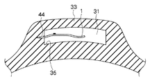
- FIG. 10 is a principal part expanded sectional view of the RFID wristband which shows 5th Embodiment.
- the inlay 1 is disposed in the storage portion 31 with one end thereof fitted in a mounting groove 44 formed in the inner wall 36 of the storage portion 31.
- FIG. 11 is an enlarged cross-sectional view of a main part of an RFID wristband according to another aspect of the fifth embodiment.
- the both ends of the inlay 1 are fitted in the mounting grooves 44 respectively formed on the opposing inner walls 36 of the storage portion 31 and are disposed in the storage portion 31.
- Both ends of the inlay 1 are fitted in the mounting groove 44, but the storage portion 31 is larger than the volume occupied by the inlay 1, so that the degree of freedom that the inlay 1 can move inside the storage portion 31 is ensured. Can do. Even if the storage portion 31 of the elastic block portion 33 is deformed by an impact from the outside, the inlay 1 stored in the storage portion 31 is not directly affected, so that the IC chip 12 and the antenna 13 are bonded. The electrode 12a can be prevented from peeling and separating. *
- FIG. 12 (a) is an enlarged cross-sectional view of the main part of an RFID wristband showing the sixth embodiment
- FIG. 12 (b) is a partial perspective view of the RFID wristband showing the sixth embodiment.
- the inlay 1 is disposed in a state where the inlay 1 is fixed to the column 38 of the inner wall 36 of the storage unit 31.
- struts 38 are formed on the inner wall 36.
- a through hole 18 is formed in the base substrate 11 of the inlay 1.
- a support column 38 formed on the inner wall 36 of the storage portion 31 is inserted into the through hole 18 of the inlay 1.
- the inlay 1 is fixed to the inner wall 36 of the storage portion 31 by inserting the support column 38 into the through hole 18 of the inlay 1.
- the through-hole 18 of the inlay 1 that is axially passed through the support column 38 is slightly larger than the diameter of the support column 38, it can move freely up and down and left and right within the range. The degree of freedom that 1 can move is ensured. As a result, it is possible to prevent the electrode 12a that bonds the IC chip 12 and the antenna 13 from being peeled or separated.
- the column 38 has a cylindrical shape, but is not limited to this shape.
Landscapes
- Engineering & Computer Science (AREA)
- Computer Hardware Design (AREA)
- Microelectronics & Electronic Packaging (AREA)
- Physics & Mathematics (AREA)
- General Physics & Mathematics (AREA)
- Theoretical Computer Science (AREA)
- Details Of Aerials (AREA)
Description
本発明は、人体の手首や足首などに環状に巻きつけて使用するRFID(Radio Frequency Identification;無線自動認識)リストバンドに係り、特に、非接触でデータの読み書き可能なインレイを内蔵するRFIDリストバンドに関する。
従来から、病院などにおいて患者の診療科、氏名、年齢、血液型などその個人固有の識別データをリストバンドに印字して表示した上で、患者の四肢、例えば手首あるいは足首に環状にゆるく巻き付けて、患者の特定を確実にすることが行われている。
さらに、上記個人情報を電子化して、非接触でデータを読み書きするために、リストバンドにインレイを内蔵する。図3に示すように、インレイ1は、ベース基材11の片面または両面に、データを記憶するICチップ12と、このICチップ12に接続して情報の送受信を行うアンテナ13と、によって構成されている。アンテナ13は、ICチップ12の電極12aと電気的に接続されている。特許文献1には、ポリエチレンあるいはその共重合体からなる基材と非接触のRFIDとを備えたリストバンドが開示されている。しかしながら、長期使用などによる耐久性の観点から、伸縮性のシリコーンゴムからなるリストバンドが求められている。
特許文献2には、凹部を有するシリコーンゴム性のリストバンドが開示されている。このリストバンドの場合、凹部にインレイを接着剤で封止している。特許文献3には、硬質フィルムでラミネートしたインレイを包含したシリコーンゴムからなるRFIDリストバンドが開示されている。
しかしながら、接着剤や硬質フィルムは可撓性や伸縮性が小さいため、シリコーンゴムの変形や伸びに対する追従性が悪い。引用文献3のように、インレイと、インレイをラミネートする硬質フィルムとが完全な密着状態にあると、屈曲作用による応力にICチップとアンテナとの接合部分が耐えきれず、断線するという問題がある。すなわち、インレイ1は、屈曲作用による応力がインレイ1に加わると、ICチップ12が割れるなどして破損したり、ICチップ12とアンテナ13を接着する電極12aが剥離・分離したりする場合がある(図13(a)および図13(b)参照)。また、インレイを硬質フィルムでラミネートしたり、接着剤で封止したりすると、生産工数が増えてしまい、材料が余分に必要となる等の問題がある。
本発明は、以上のような諸問題に鑑みなされたもので、外部からの衝撃や引っ張りや折り曲げを受けても、ICチップが割れるなどして破損したり、ICチップとアンテナを接着する電極が剥離・分離したりすることがないRFIDリストバンドを提供することを課題とする。 また、本発明は、インレイを収納する収納部に余裕を持たせ、インレイが移動可能な自由度を確保したRFIDリストバンドを提供することを課題とする。 さらに、本発明は、手首や足首に装着されることにより手首や足首に沿うように湾曲するが、収納部に収納するインレイ自体に負荷のかからないRFIDリストバンドを提供することを課題とする。 さらに、本発明は、生産工程の手間を減らし、材料を削減可能なRFIDリストバンドを提供することを課題とする。
すなわち本発明は、気密な収納部を有する弾性ブロック部と、前記弾性ブロック部と連結されることで環状を構成する弾性バンド部と、前記収納部に収納される、ベース基材と前記ベース基材上のアンテナと前記アンテナに電気的に接続されたICチップとを有するインレイと、を備えるRFIDリストバンドであって、前記インレイは前記収納部の内壁に固定されず、かつ、前記収納部は前記インレイの占める体積よりも大きいことを特徴とするRFIDリストバンドである。 好ましくは、前記インレイと接する前記収納部の内壁の少なくとも一部は凹凸面で構成されている。
第二の発明は、気密な収納部を有する弾性ブロック部と、前記弾性ブロック部と連結されることで環状を構成する弾性バンド部と、前記収納部に収納される、ベース基材と前記ベース基材上のアンテナと前記アンテナに電気的に接続されたICチップとを有するインレイと、を備えるRFIDリストバンドであって、前記インレイの一部は前記収納部の内壁に固定され、かつ、前記収納部は前記インレイの占める体積よりも大きいことを特徴とするRFIDリストバンドである。 好ましくは、前記インレイは前記インレイの一部に形成する点留め部によって前記収納部の内壁に固定されている。 好ましくは、前記インレイの一部は前記収納部の内壁に形成された隆起部によって固定されている。 好ましくは、前記インレイは前記収納部の内壁に形成された少なくとも1つの装着溝によって嵌装されている。 好ましくは、前記インレイは貫通孔を有し、該貫通孔が前記収容部の内壁に形成された支柱に軸通されている。好ましくは、前記インレイはフィルムによりラミネートされていない状態であっても良い。 好ましくは、前記弾性ブロック部と前記弾性バンド部とが異なる色を有しても良い。 好ましくは、前記弾性ブロック部と前記弾性バンド部とが異なる硬度を有しても良い。 好ましくは、前記弾性ブロック部と前記弾性バンド部とがシリコーン樹脂で構成されていることが望ましい。
本発明のRFIDリストバンドによれば、インレイに、外部からの衝撃や引っ張りおよび折り曲げによる応力を受けても、ICチップが割れるなどして破損したり、ICチップとアンテナを接着する電極が剥離・分離したりすることを防止できるので、耐久性が向上するとともに、安定した通信性能を得ることができる。
以下、本発明のRFIDリストバンドについて、図面を参照して説明する。本発明は以下の好ましい実施の形態により説明されるが、本発明の範囲を逸脱することなく、多くの手法により変更を行うことができ、本実施の形態以外の他の実施の形態を利用することができる。従って、本発明の範囲内における全ての変更が特許請求の範囲に含まれる。
図1は、RFIDリストバンドの斜視図である。図2は、RFIDリストバンドの周方向に沿った断面図である。RFIDリストバンド30は、弾性ブロック部33と、この弾性ブロック部33の両端に連結して環状になる弾性バンド部34と、によって構成される。弾性ブロック部33は、内部にインレイ1を収納する収納部31が形成されている。
収納部31は、弾性ブロック部33または弾性バンド部34の一部で構成される複数の内壁36で囲まれることにより形成される気密な空間である。また、収納部31は、インレイ1の占める体積(嵩)より大きく形成されている。この収納部31の詳細は、後述する第1実施形態~第6実施形態で説明する。
弾性ブロック部33および弾性バンド部34は、弾性部材で構成されているので、容易に延伸し、手首や足首等に快適にフィットすることが可能である。弾性部材を構成する材料としては、例えば、熱硬化性ウレタンゴム、熱硬化性シリコーンゴム等を用いることができる。その他には、スチレン系熱可塑性エラストマー、オレフィン系熱可塑性エラストマー、ウレタン系熱可塑性エラストマー、ポリエステル系熱可塑性エラストマー、ポリアミド系熱可塑性エラストマー、フッ素系熱可塑性エラストマー等の熱可塑性エラストマーを用いることができる。これらの中でも特に、耐候性、耐熱性、耐薬品性、柔軟性等に優れ、比誘電率の低い熱硬化性シリコーンゴムが好ましい。
また、弾性ブロック部33および弾性バンド部34は、その硬度を適宜選択することができる。例えば、弾性ブロック部33および弾性バンド部34の硬度を、同じにすることも、異ならせることもできる。弾性ブロック部33はゴム硬度を高くし、弾性バンド部34はゴム硬度を低くすることで、手首に取り付ける際、弾性バンド部34が伸縮しても弾性ブロック部33の伸縮率を少なく抑えることができる。
さらに、弾性ブロック部33および弾性バンド部34は、公知の無機顔料、有機顔料、染料などの着色剤を任意に含有することができる。例えば、弾性ブロック部33になる材料にカーボンブラックなどの黒色顔料を含有させ、弾性バンド部34になる材料に酸化チタン等の白色顔料を含有させると、弾性ブロック部33と弾性バンド部34とを見分けることができる。これにより、RFIDリストバンド30中でインレイ1を実装している弾性ブロック部33が容易に視認でき、インレイ1を実装している弾性ブロック部33をリーダライタ(不図示)に確実に近接させ、データを容易に読み取ることができる。
RFIDリストバンド30を医療用に用いる場合、弾性ブロック部33および弾性バンド部34に抗菌剤を含有させることにより、抗菌性を付与することができる。抗菌剤としては、シリカゲル銀、銀ゼオライト、リン酸カルシウム銀などの銀系抗菌剤、酸化亜鉛系抗菌剤、ベンゾイミダゾール系抗菌剤、トリアジン系抗菌剤、ピリチオン系抗菌剤、ニトリル系抗菌剤、有機ヨード系抗菌剤などを用いることができる。
次に、収納部31に収納されるインレイ1の構成について説明する。図3(a)は、RFIDリストバンドに内蔵されるインレイの概略構成図である。図3(b)は、インレイのICチップ実装部の要部拡大断面図である。尚、図3(a)および図3(b)は、図13(a)および図13(b)と同一の構成のため同一の符号を付している。インレイ1は、リーダライタとの間で非接触通信ができる非接触IC回路であって、ベース基材11の片面または両面に、データを記憶するICチップ12と、このICチップ12に接続して情報の送受信を行うアンテナ13と、によって構成されている。アンテナ13は、ICチップ12の電極12aと電気的に接続されている。尚、インレイ1は、ベース基材11自体が薄い材料であるため、波打っていたり、湾曲したりしていることが多い。
インレイ1は、例えば、UHF帯(300MHz~3GHz(好ましくは860~960MHz、さらに具体的には、433MHz、900MHz、915~928MHz、950~958MHz)やマイクロ波(1~30GHz、具体的には2.45GHz)、HF帯(3MHz~30MHz(好ましくは13.56MHz))あるいは135kHz以下等、その他、所定の周波数帯の電波および電磁的作用等により、アンテナ13を介してICチッ
プ12に必要なデータの無線による読み取りおよび書き込み(データ通信)を行う。インレイ1は、それぞれの使用電波に応じてICチップ12およびアンテナ13の具体的構成を適正なものとしている。
プ12に必要なデータの無線による読み取りおよび書き込み(データ通信)を行う。インレイ1は、それぞれの使用電波に応じてICチップ12およびアンテナ13の具体的構成を適正なものとしている。
インレイ1に使用されるベース基材11の材料としては、例えば、ポリエチレンテレフタレート、ポリエチレンナフタレート、ポリブチレンテレフタレート、ポリエチレンテレフタレート/イソフタレート共重合体などのポリエステル類、ポリエチレン、ポリプロピレン等のポリオレフィン樹脂、ポリフッ化ビニル、ポリフッ化ビニリデン、ポリ4フッ化エチレン、エチレン-4フッ化エチレン共重合体等のポリフッ化エチレン系樹脂、ナイロン6、ナイロン66等のポリアミド、ポリ塩化ビニル、塩化ビニル/酢酸ビニル共重合体、エチレン/酢酸ビニル共重合体、エチレン/ビニルアルコール共重合体等のビニル系樹脂、三酢酸セルロース、セロハン等のセルロース系樹脂、ポリメタアクリル酸メチル、ポリメタアクリル酸エチル、ポリアクリル酸エチル、ポリアクリル酸ブチル等のアクリル系樹脂、ポリスチレン、ポリカーボネート、ポリイミド等の単体または混合物を用いることができ、絶縁性の有機材料であれば用いることができる。
アンテナ13は、例えば、銅箔、アルミニウム箔などの導電性箔からなる。ベース基材11上に銅箔、アルミニウム箔などの導電性箔を形成し、その導電性箔をエッチングすることにより導電性箔で構成されるアンテナ13を得ることができる。別の方法として、ベース基材11上に導電性インクを印刷することにより、導電性インクで構成されるアンテナ13を得ることができる。 尚、インレイ1の片面または両面をフィルムでラミネートしても良い。インレイ1をフィルムによるラミネートをしない場合、生産工程の手間を減らし、材料を削減することができる。
図4は、別態様のインレイ1のICチップ実装部の要部拡大断面図であり、インレイ1のICチップ6部分にポッティング加工により被覆部16を形成している。被覆部16は、紫外線硬化型の樹脂やエポキシ樹脂などの熱反応硬化型あるいは二液混合反応硬化型の液状樹脂で被覆した後、これを硬化させたものである。その他、熱可塑性樹脂や熱硬化性樹脂に、ガラス繊維、カーボン繊維、アラミド繊維、セラミック繊維(シリコンカーバイド、ボロン、アルミナ)、ウィスカー(Al2O3、β-SiC、グラファイト、チタン酸カリウム、ポリオキシメチレン)等を含有するものを用いることができる。これらの中でも特に、ガラス繊維入りのエポキシ樹脂が好ましい。この被覆部16により、ICチップ12およびICチップ12とアンテナ13とを接着する電極12aが保護できるので、耐衝撃性をさらに向上させることができる。
次に、図5~図12を参照して、インレイ1を収納部31に配置させる態様について説明する。
(第1実施形態) 図5は、第1実施形態を示すRFIDリストバンドの要部拡大断面図である。インレイ1は、インレイ1の占める体積よりも大きい収納部31に収納されているが、いずれの内壁36にも固定されない状態で配置されている。たとえ、弾性ブロック部33に外部から衝撃を受けて、内部の収納部31が大きく変形したりねじれても、インレイ1は収納部31の内部で自由に移動可能で、直接的に応力が加わることがないので、ICチップ12が割れて破損したり、ICチップ12とアンテナ13とを接着する電極12aが剥離・分離するのを防止できる。また、収納部31は、気密性が保たれているため、インレイ1が浸水等によって通信不能になることがないため、耐久性の高いRFIDリストバンド30を形成することができる。
このRFIDリストバンド30は、以下のようにして作成する。図6(a)に示すように、下金型(不図示)の凹部に、熱硬化性シリコーンゴムなどの弾性部材を配置し、上金型(不図示)を下金型に押し付け、加熱加圧することによって、挿入孔46を有する弾性ブロック部33が形成される(1次成形、半加硫状態)。図6(b)に示すように、インレイ1は、弾性ブロック部33の挿入孔46に挿入される。 図6(c)に示すように、1次成形により形成された弾性ブロック部33の両端に、弾性バンド部34用の弾性部材を配置して加熱加圧することによって、弾性ブロック部33と弾性バンド部34とが溶着し、環状に形成される(2次成形、加硫状態)。この場合、弾性ブロック部33の貫通孔46を完全に塞ぐようにして弾性バンド部34が溶着されるので、弾性ブロック部33には密閉された収納部31が形成できる。
(第2実施形態) 図7は、第2実施形態を示すRFIDリストバンドの要部拡大断面図である。インレイ1は、収納部31のいずれの内壁36にも固定されない状態で配置されている。
第2実施形態では、インレイ1と接する収納部31の内壁36の少なくとも一部は凹凸面37で構成されている。収納部31の内壁36の一部を凹凸面37にすることによって、インレイ1と内壁36との接触面積が小さくなり、互いに密着していない状態になる。それにより、インレイ1と内壁36との間で生じる摩擦抵抗を軽減することができ、曲げ作用時に発生する層間における応力を緩和できる。従って、弾性ブロック部33が湾曲する場合であっても、収納部31内においてインレイ1の自由度が確保されているので、収納部31に配置されたインレイ1に負荷がかかることを防止できる。そして、ICチップ12とアンテナ13とを接着する電極12aが剥離・分離するのを防止することができる。尚、凹凸面37のトップとボトムの差は0.1mm~2.0mmであることが好ましい。0.1mm未満では凹凸面37として機能せず、2.0mmより大きいと、屈曲時に凹凸面37の凸部によってICチップ12とアンテナ13とを接着する電極12aが剥離・分離する場合がある。
(第3実施形態) 図8は、第3実施形態を示すRFIDリストバンドの要部拡大断面図である。第3実施形態では、インレイ1の一部に点留め部40を形成する。この点留め部40は、インレイ1のごく小さな部分である。この点留め部40は、加熱溶融圧着、ヒートシール、高周波ウェルダー融着、超音波ウェルダー融着などの公知の熱融着手段によって形成される。
このように、点留め部40によってインレイ1の一部を収納部31の内壁36に固定することで、収納部31内でインレイ1が動き回り過ぎない。たとえ、外部からの曲げや衝撃を受けても、収納部31の内部でインレイ1が移動可能な自由度を確保しているので、直接的に応力が加わることなく、ICチップ12の破損を防止できる。また、弾性バンド部33が伸縮したり、湾曲したりして、収納部31が大きく変形したりねじれても、収納部31の内壁36とインレイ1とは、別々な変形をするので、ICチップ12とアンテナ13とを接着する電極12aが剥離・分離するのを防止できる。
(第4実施形態) 図9は、第4実施形態を示すRFIDリストバンドの要部拡大断面図である。第4実施形態では、インレイ1の一部が収納部31の内壁36に形成された隆起部42に固定された状態でインレイ1が収納部31に配置されている。収納部31は、インレイ1の占める体積より大きい。インレイ1は、隆起部42を除き内壁36とは接触していない。インレイ1の一部を隆起部42に接着する方法としては、加熱溶融圧着、ヒートシール、高周波ウェルダー融着、超音波ウェルダー融着などの公知の熱融着手段により容易に加工できる。その他の接着方法として、簡易的な耐熱性の両面テープ接着、ホットメルト溶着等を使用することができる。特に、耐熱性の両面テープを使用する方法が好ましい。
インレイ1は、その一部が隆起部42に固定されているので、収納部31の内部でインレイ1が移動可能な自由度を確保することができる。外部から衝撃で弾性ブロック部33の収納部31が変形したとしても、収納部31内に収納されているインレイ1は、直接的に影響を受けないので、ICチップ12とアンテナ13とを接着する電極12aが剥離・分離するのを防止することができる。
(第5実施形態) 図10は、第5実施形態を示すRFIDリストバンドの要部拡大断面図である。インレイ1は、その一端を収納部31の内壁36に形成された装着溝44に嵌装した状態で、収納部31に配置されている。図11は、第5実施形態の別の態様のRFIDリストバンドの要部拡大断面図である。収納部31の対向する内壁36にそれぞれ形成された装着溝44にインレイ1の両端が嵌装された状態で、収納部31に配置されている。インレイ1の両端は、装着溝44に嵌装された状態となるが、収納部31はインレイ1の占める体積より大きいので、収納部31の内部でインレイ1が移動可能な自由度を確保することができる。外部から衝撃で弾性ブロック部33の収納部31が変形したとしても、収納部31内に収納されているインレイ1は、直接的に影響を受けないので、ICチップ12とアンテナ13とを接着する電極12aが剥離・分離するのを防止できる。
(第6実施形態) 図12(a)は第6実施形態を示すRFIDリストバンドの要部拡大断面図であり、図12(b)は第6実施形態を示すRFIDリストバンドの部分斜視図である。収納部31の内壁36の支柱38にインレイ1が固定された状態で配置されている。 第6実施形態では、内壁36に支柱38が形成されている。インレイ1のベース基材11には貫通孔18が形成されている。インレイ1の貫通孔18に収納部31の内壁36に形成された支柱38が挿入されている。支柱38がインレイ1の貫通孔18に挿入されることで、インレイ1は収納部31の内壁36に固定された状態となる。支柱38に軸通されるインレイ1の貫通孔18は、支柱38の径よりも若干大きいため、その範囲内であれば、上下左右に自由に動き回ることができるので、収納部31の内部でインレイ1が移動可能な自由度を確保することができる。その結果、ICチップ12とアンテナ13とを接着する電極12aが剥離・分離するのを防止できる。尚、図12(a)および図12(b)において支柱38は円柱形状であるが、この形状に限定されるものではない。
1 インレイ11 ベース基材12 ICチップ12a 電極13 アンテナ16 被覆部18 貫通孔30 RFIDリストバンド31 収納部33 弾性ブロック部34 弾性バンド部36 内壁37 凹凸面38 支柱40 点留め部42 隆起部44 装着溝46 挿入孔
Claims (11)
- 気密な収納部を有する弾性ブロック部と、 前記弾性ブロック部と連結されることで環状を構成する弾性バンド部と、 前記収納部に収納される、ベース基材と前記ベース基材上のアンテナと前記アンテナに電気的に接続されたICチップとを有するインレイと、を備えるRFIDリストバンドであって、 前記インレイは前記収納部の内壁に固定されず、かつ、前記収納部は前記インレイの占める体積よりも大きいことを特徴とするRFIDリストバンド。
- 前記インレイと接する前記収納部の内壁の少なくとも一部は凹凸面で構成されていることを特徴とする請求項1記載のRFIDリストバンド。
- 気密な収納部を有する弾性ブロック部と、 前記弾性ブロック部と連結されることで環状を構成する弾性バンド部と、 前記収納部に収納される、ベース基材と前記ベース基材上のアンテナと前記アンテナに電気的に接続されたICチップとを有するインレイと、を備えるRFIDリストバンドであって、 前記インレイの一部は前記収納部の内壁に固定され、かつ、前記収納部は前記インレイの占める体積よりも大きいことを特徴とするRFIDリストバンド。
- 前記インレイは前記インレイの一部に形成する点留め部によって前記収納部の内壁に固定されていることを特徴とする請求項3記載のRFIDリストバンド。
- 前
記インレイの一部は前記収納部の内壁に形成された隆起部によって固定されていることを特徴とする請求項3記載のRFIDリストバンド。 - 前記インレイは前記収納部の内壁に形成された少なくとも1つの装着溝によって嵌装されていることを特徴とする請求項3記載のRFIDリストバンド。
- 前記インレイは貫通孔を有し、該貫通孔が前記収容部の内壁に形成された支柱に軸通されていることを特徴とする請求項3記載のRFIDリストバンド。
- 前記インレイはフィルムによりラミネートされていない状態であることを特徴とする請求項1乃至7のいずれかに記載のRFIDリストバンド。
- 前記弾性ブロック部と前記弾性バンド部とが異なる色を有することを特徴とする請求項1乃至8のいずれかに記載のRFIDリストバンド。
- 前記弾性ブロック部と前記弾性バンド部とが異なる硬度を有することを特徴とする請求項1乃至9のいずれかに記載のRFIDリストバンド。
- 前記弾性ブロック部と前記弾性バンド部とがシリコーン樹脂で構成されていることを特徴とする請求項1乃至10のいずれかに記載のRFIDリストバンド。
Priority Applications (2)
| Application Number | Priority Date | Filing Date | Title |
|---|---|---|---|
| EP13820483.9A EP2876578B1 (en) | 2012-07-17 | 2013-06-12 | Rfid wrist band |
| US14/414,731 US9336477B2 (en) | 2012-07-17 | 2013-06-12 | RFID wrist band |
Applications Claiming Priority (2)
| Application Number | Priority Date | Filing Date | Title |
|---|---|---|---|
| JP2012158532A JP5901457B2 (ja) | 2012-07-17 | 2012-07-17 | Rfidリストバンド |
| JP2012-158532 | 2012-07-17 |
Publications (1)
| Publication Number | Publication Date |
|---|---|
| WO2014013818A1 true WO2014013818A1 (ja) | 2014-01-23 |
Family
ID=49948653
Family Applications (1)
| Application Number | Title | Priority Date | Filing Date |
|---|---|---|---|
| PCT/JP2013/066157 Ceased WO2014013818A1 (ja) | 2012-07-17 | 2013-06-12 | Rfidリストバンド |
Country Status (4)
| Country | Link |
|---|---|
| US (1) | US9336477B2 (ja) |
| EP (1) | EP2876578B1 (ja) |
| JP (1) | JP5901457B2 (ja) |
| WO (1) | WO2014013818A1 (ja) |
Families Citing this family (18)
| Publication number | Priority date | Publication date | Assignee | Title |
|---|---|---|---|---|
| US9313609B2 (en) * | 2012-12-28 | 2016-04-12 | Joseph Nicholi Prencipe | Contact information social exchange method and system |
| USD749976S1 (en) * | 2014-09-09 | 2016-02-23 | Adriana Barresi | Football bracelet |
| JP2016168289A (ja) | 2015-03-16 | 2016-09-23 | カシオ計算機株式会社 | バンド及び電子機器 |
| US9805298B2 (en) * | 2015-10-02 | 2017-10-31 | Mitac Computing Technology Corporation | Wrist worn RFID device with security protection and method thereof |
| USD782053S1 (en) * | 2016-01-05 | 2017-03-21 | Rhonda Ferguson-Shakir | Diagnostic wrist band |
| USD840859S1 (en) * | 2016-08-29 | 2019-02-19 | Maneesh SETHI | Adjustable wristband |
| US20180078009A1 (en) * | 2016-09-21 | 2018-03-22 | Zandy Luig | Rubber ring with interchangeable jewelry |
| US10575988B2 (en) | 2017-10-12 | 2020-03-03 | Amo Development, Llc | Ophthalmic docking system with 3-dimensional automatic positioning using differential RF coupling |
| US10568765B2 (en) | 2017-10-17 | 2020-02-25 | Amo Development, Llc | Ophthalmic docking system with 3-dimensional automatic positioning using magnetic sensing array |
| DE102018209818B4 (de) * | 2018-06-18 | 2024-10-10 | Bundesdruckerei Gmbh | Verfahren zum Herstellen eines Wert- oder Sicherheitsdokumentenrohlings mit einer elektronischen Schaltung, ein Wert- oder Sicherheitsdokumentenrohling und ein Sicherheits- und Wertdokument |
| JP2022143184A (ja) * | 2021-03-17 | 2022-10-03 | サトーホールディングス株式会社 | Rfidアンテナ、rfidインレイおよびrfidラベル |
| USD1029672S1 (en) * | 2022-02-28 | 2024-06-04 | Johnny Henderson | Wristband |
| GB2622767A (en) * | 2022-08-03 | 2024-04-03 | Wristband Id Ltd | An identification device and associated system |
| DE102022121101A1 (de) | 2022-08-22 | 2024-02-22 | PAYCELET GmbH | Verschluss und Armband mit einem solchen Verschluss |
| US12387078B2 (en) | 2022-12-22 | 2025-08-12 | Rivendell Creations Llc | Near field communication housing structure |
| FR3163187A1 (fr) * | 2024-06-05 | 2025-12-12 | Idemia France | Carte à puce avec couche d’incrustation encapsulant une partie de bouchage en fibres de carbone |
| US20250375021A1 (en) * | 2024-06-06 | 2025-12-11 | Jennifer Heinzman | Adjustable Harness Device for Carrying Personal Items |
| USD1112753S1 (en) * | 2024-07-15 | 2026-02-10 | Darroch Medical Solutions, Inc. | Wristwatch |
Citations (5)
| Publication number | Priority date | Publication date | Assignee | Title |
|---|---|---|---|---|
| JPH03197195A (ja) * | 1989-12-27 | 1991-08-28 | Omron Corp | ブレスレット型非接触記録媒体 |
| JP2002202723A (ja) * | 2000-12-28 | 2002-07-19 | Nagase & Co Ltd | 電子タグ付きバンド |
| JP2003296675A (ja) | 2002-03-29 | 2003-10-17 | Seiko Precision Inc | Rf−id用リストバンド |
| JP2005283992A (ja) | 2004-03-30 | 2005-10-13 | Sato Corp | リストバンド |
| JP2007286213A (ja) | 2006-04-14 | 2007-11-01 | Hitachi Ltd | 装着バンドおよび装着バンドの製造方法 |
Family Cites Families (5)
| Publication number | Priority date | Publication date | Assignee | Title |
|---|---|---|---|---|
| US5265265A (en) * | 1990-02-09 | 1993-11-23 | Seiko Epson Corporation | Wristwatch radio communication device having an improved noise shielding structure |
| US7240446B2 (en) * | 2005-04-18 | 2007-07-10 | Precision Dynamics Corporation | Identification bracelet with sealable window |
| US20090273439A1 (en) * | 2008-05-01 | 2009-11-05 | Richard Selsor | Micro-chip ID |
| TW201112158A (en) * | 2009-09-18 | 2011-04-01 | Univ Nat Kaohsiung Applied Sci | Hand ring having a biomedical monitoring function |
| US8205370B2 (en) * | 2010-03-01 | 2012-06-26 | Disney Enterprises, Inc. | Two-piece wristband with interchangeable lasso band element for user selectable sizing |
-
2012
- 2012-07-17 JP JP2012158532A patent/JP5901457B2/ja not_active Expired - Fee Related
-
2013
- 2013-06-12 WO PCT/JP2013/066157 patent/WO2014013818A1/ja not_active Ceased
- 2013-06-12 US US14/414,731 patent/US9336477B2/en not_active Expired - Fee Related
- 2013-06-12 EP EP13820483.9A patent/EP2876578B1/en active Active
Patent Citations (5)
| Publication number | Priority date | Publication date | Assignee | Title |
|---|---|---|---|---|
| JPH03197195A (ja) * | 1989-12-27 | 1991-08-28 | Omron Corp | ブレスレット型非接触記録媒体 |
| JP2002202723A (ja) * | 2000-12-28 | 2002-07-19 | Nagase & Co Ltd | 電子タグ付きバンド |
| JP2003296675A (ja) | 2002-03-29 | 2003-10-17 | Seiko Precision Inc | Rf−id用リストバンド |
| JP2005283992A (ja) | 2004-03-30 | 2005-10-13 | Sato Corp | リストバンド |
| JP2007286213A (ja) | 2006-04-14 | 2007-11-01 | Hitachi Ltd | 装着バンドおよび装着バンドの製造方法 |
Also Published As
| Publication number | Publication date |
|---|---|
| US9336477B2 (en) | 2016-05-10 |
| JP2014021644A (ja) | 2014-02-03 |
| EP2876578A4 (en) | 2016-07-13 |
| JP5901457B2 (ja) | 2016-04-13 |
| EP2876578A1 (en) | 2015-05-27 |
| US20150206044A1 (en) | 2015-07-23 |
| EP2876578B1 (en) | 2020-02-19 |
Similar Documents
| Publication | Publication Date | Title |
|---|---|---|
| JP5901457B2 (ja) | Rfidリストバンド | |
| KR100330651B1 (ko) | Ic카드용 모듈, ic카드, 및 ic카드용 모듈의 제조방법 | |
| JP2004362341A (ja) | Icタグ | |
| US9159015B2 (en) | Flexible tag | |
| JP6582155B2 (ja) | 配線基板及び配線基板の製造方法 | |
| CN112997588B (zh) | 配线基板和配线基板的制造方法 | |
| CN111201839A (zh) | 配线基板和配线基板的制造方法 | |
| KR100945758B1 (ko) | Rfid 태그 | |
| CN101308549A (zh) | 无线ic标签和天线的制造方法 | |
| WO2012170492A1 (en) | Insert for enclosing electronics | |
| JP2008046668A (ja) | Rfidタグ | |
| JP2009277256A (ja) | Rfidタグ | |
| JPWO2009004728A1 (ja) | Rfidタグおよびrfidタグの製造方法 | |
| CN115297772A (zh) | 生物传感器 | |
| KR20170001080U (ko) | 전자 디바이스를 위한 신호 전송 시스템 | |
| EP2131392A1 (en) | Electronic device, electronic apparatus mounting electronic device, article mounting electronic device, and method for manufacturing electronic device | |
| JP2010250504A (ja) | Rfidタグおよびrfidタグの製造方法 | |
| JP4755524B2 (ja) | リストバンド | |
| JP7558052B2 (ja) | 伸縮性配線基板 | |
| JP2001167240A (ja) | Icタグ | |
| JP2007286214A (ja) | 装着バンド | |
| JP7269544B2 (ja) | 配線基板及び配線基板の製造方法 | |
| KR200399612Y1 (ko) | 전자인식 태그 | |
| TWI656816B (zh) | 電子卡及其製作方法 | |
| JP2003099746A (ja) | 非接触通信媒体 |
Legal Events
| Date | Code | Title | Description |
|---|---|---|---|
| 121 | Ep: the epo has been informed by wipo that ep was designated in this application |
Ref document number: 13820483 Country of ref document: EP Kind code of ref document: A1 |
|
| WWE | Wipo information: entry into national phase |
Ref document number: 14414731 Country of ref document: US |
|
| NENP | Non-entry into the national phase |
Ref country code: DE |
|
| WWE | Wipo information: entry into national phase |
Ref document number: 2013820483 Country of ref document: EP |