WO2014017005A1 - 発光モジュール - Google Patents
発光モジュール Download PDFInfo
- Publication number
- WO2014017005A1 WO2014017005A1 PCT/JP2013/003280 JP2013003280W WO2014017005A1 WO 2014017005 A1 WO2014017005 A1 WO 2014017005A1 JP 2013003280 W JP2013003280 W JP 2013003280W WO 2014017005 A1 WO2014017005 A1 WO 2014017005A1
- Authority
- WO
- WIPO (PCT)
- Prior art keywords
- light emitting
- emitting element
- block
- block group
- power consumption
- Prior art date
- Legal status (The legal status is an assumption and is not a legal conclusion. Google has not performed a legal analysis and makes no representation as to the accuracy of the status listed.)
- Ceased
Links
Images


Classifications
-
- F—MECHANICAL ENGINEERING; LIGHTING; HEATING; WEAPONS; BLASTING
- F21—LIGHTING
- F21K—NON-ELECTRIC LIGHT SOURCES USING LUMINESCENCE; LIGHT SOURCES USING ELECTROCHEMILUMINESCENCE; LIGHT SOURCES USING CHARGES OF COMBUSTIBLE MATERIAL; LIGHT SOURCES USING SEMICONDUCTOR DEVICES AS LIGHT-GENERATING ELEMENTS; LIGHT SOURCES NOT OTHERWISE PROVIDED FOR
- F21K9/00—Light sources using semiconductor devices as light-generating elements, e.g. using light-emitting diodes [LED] or lasers
- F21K9/60—Optical arrangements integrated in the light source, e.g. for improving the colour rendering index or the light extraction
- F21K9/64—Optical arrangements integrated in the light source, e.g. for improving the colour rendering index or the light extraction using wavelength conversion means distinct or spaced from the light-generating element, e.g. a remote phosphor layer
-
- F—MECHANICAL ENGINEERING; LIGHTING; HEATING; WEAPONS; BLASTING
- F21—LIGHTING
- F21S—NON-PORTABLE LIGHTING DEVICES; SYSTEMS THEREOF; VEHICLE LIGHTING DEVICES SPECIALLY ADAPTED FOR VEHICLE EXTERIORS
- F21S8/00—Lighting devices intended for fixed installation
- F21S8/02—Lighting devices intended for fixed installation of recess-mounted type, e.g. downlighters
- F21S8/026—Lighting devices intended for fixed installation of recess-mounted type, e.g. downlighters intended to be recessed in a ceiling or like overhead structure, e.g. suspended ceiling
-
- H—ELECTRICITY
- H05—ELECTRIC TECHNIQUES NOT OTHERWISE PROVIDED FOR
- H05B—ELECTRIC HEATING; ELECTRIC LIGHT SOURCES NOT OTHERWISE PROVIDED FOR; CIRCUIT ARRANGEMENTS FOR ELECTRIC LIGHT SOURCES, IN GENERAL
- H05B45/00—Circuit arrangements for operating light-emitting diodes [LED]
-
- H—ELECTRICITY
- H05—ELECTRIC TECHNIQUES NOT OTHERWISE PROVIDED FOR
- H05B—ELECTRIC HEATING; ELECTRIC LIGHT SOURCES NOT OTHERWISE PROVIDED FOR; CIRCUIT ARRANGEMENTS FOR ELECTRIC LIGHT SOURCES, IN GENERAL
- H05B45/00—Circuit arrangements for operating light-emitting diodes [LED]
- H05B45/40—Details of LED load circuits
-
- H—ELECTRICITY
- H05—ELECTRIC TECHNIQUES NOT OTHERWISE PROVIDED FOR
- H05B—ELECTRIC HEATING; ELECTRIC LIGHT SOURCES NOT OTHERWISE PROVIDED FOR; CIRCUIT ARRANGEMENTS FOR ELECTRIC LIGHT SOURCES, IN GENERAL
- H05B45/00—Circuit arrangements for operating light-emitting diodes [LED]
- H05B45/50—Circuit arrangements for operating light-emitting diodes [LED] responsive to malfunctions or undesirable behaviour of LEDs; responsive to LED life; Protective circuits
- H05B45/56—Circuit arrangements for operating light-emitting diodes [LED] responsive to malfunctions or undesirable behaviour of LEDs; responsive to LED life; Protective circuits involving measures to prevent abnormal temperature of the LEDs
-
- H—ELECTRICITY
- H10—SEMICONDUCTOR DEVICES; ELECTRIC SOLID-STATE DEVICES NOT OTHERWISE PROVIDED FOR
- H10W—GENERIC PACKAGES, INTERCONNECTIONS, CONNECTORS OR OTHER CONSTRUCTIONAL DETAILS OF DEVICES COVERED BY CLASS H10
- H10W90/00—Package configurations
-
- F—MECHANICAL ENGINEERING; LIGHTING; HEATING; WEAPONS; BLASTING
- F21—LIGHTING
- F21Y—INDEXING SCHEME ASSOCIATED WITH SUBCLASSES F21K, F21L, F21S and F21V, RELATING TO THE FORM OR THE KIND OF THE LIGHT SOURCES OR OF THE COLOUR OF THE LIGHT EMITTED
- F21Y2105/00—Planar light sources
- F21Y2105/10—Planar light sources comprising a two-dimensional [2D] array of point-like light-generating elements
-
- F—MECHANICAL ENGINEERING; LIGHTING; HEATING; WEAPONS; BLASTING
- F21—LIGHTING
- F21Y—INDEXING SCHEME ASSOCIATED WITH SUBCLASSES F21K, F21L, F21S and F21V, RELATING TO THE FORM OR THE KIND OF THE LIGHT SOURCES OR OF THE COLOUR OF THE LIGHT EMITTED
- F21Y2113/00—Combination of light sources
- F21Y2113/10—Combination of light sources of different colours
- F21Y2113/13—Combination of light sources of different colours comprising an assembly of point-like light sources
-
- F—MECHANICAL ENGINEERING; LIGHTING; HEATING; WEAPONS; BLASTING
- F21—LIGHTING
- F21Y—INDEXING SCHEME ASSOCIATED WITH SUBCLASSES F21K, F21L, F21S and F21V, RELATING TO THE FORM OR THE KIND OF THE LIGHT SOURCES OR OF THE COLOUR OF THE LIGHT EMITTED
- F21Y2115/00—Light-generating elements of semiconductor light sources
- F21Y2115/10—Light-emitting diodes [LED]
-
- Y—GENERAL TAGGING OF NEW TECHNOLOGICAL DEVELOPMENTS; GENERAL TAGGING OF CROSS-SECTIONAL TECHNOLOGIES SPANNING OVER SEVERAL SECTIONS OF THE IPC; TECHNICAL SUBJECTS COVERED BY FORMER USPC CROSS-REFERENCE ART COLLECTIONS [XRACs] AND DIGESTS
- Y02—TECHNOLOGIES OR APPLICATIONS FOR MITIGATION OR ADAPTATION AGAINST CLIMATE CHANGE
- Y02B—CLIMATE CHANGE MITIGATION TECHNOLOGIES RELATED TO BUILDINGS, e.g. HOUSING, HOUSE APPLIANCES OR RELATED END-USER APPLICATIONS
- Y02B20/00—Energy efficient lighting technologies, e.g. halogen lamps or gas discharge lamps
- Y02B20/30—Semiconductor lamps, e.g. solid state lamps [SSL] light emitting diodes [LED] or organic LED [OLED]
Definitions
- the present invention relates to a light emitting module in which light emitting elements such as LEDs are two-dimensionally mounted on a substrate.
- a light emitting module using an LED has advantages such as long life, small size, good luminous efficiency, and a bright emission color, and is widely used for backlights of lighting devices and display devices.
- a light emitting module used in a large-capacity lighting device such as a downlight
- a light emitting module is also obtained by mounting a large number of LED chips on a single substrate in a two-dimensional form and covering the same with a sealing material to seal the light emitting module. Has been developed.
- the light emitting device disclosed in Patent Document 1 has the same number of LED chips connected in parallel in each element row, and the entire circuit. The balance of composition is improved.
- the LED chips are usually mounted at a high density in a mounting region on the substrate in order to emit light with high luminance.
- the present invention provides a light-emitting module in which a plurality of light-emitting element blocks each having a plurality of light-emitting elements connected in series are arranged side by side on the substrate, and the light-emitting element blocks are connected in parallel. It aims at reducing the temperature rise of a part.
- a light-emitting module includes a light-emitting element block in which a plurality of light-emitting element blocks each having a plurality of light-emitting elements connected in series are arranged on a substrate and semiconductor elements are two-dimensionally arranged.
- the plurality of light-emitting element blocks arranged on the substrate include a light-emitting element block belonging to the first block group located in the central portion and a first block group Light emitting element blocks belonging to the second block group located on both sides of the light emitting element block, and the second block group includes light emitting element blocks whose power consumption is higher than the power consumption of the light emitting element blocks belonging to the first block group. I made it.
- the power consumption of the light emitting element blocks belonging to the first block group located in the central part is smaller than the power consumption of the light emitting element blocks belonging to the second block group located on both sides thereof.
- the temperature distribution is made uniform on both sides, and the temperature rise at the center is reduced.
- FIG. 3 is a perspective view of a lamp unit 6 in the lighting device 1. 3 is an exploded perspective view of the lamp unit 6.
- FIG. 2 is a plan view illustrating an example of a light emitting module 10.
- FIG. 3 is a plan view showing light emitting element blocks 21 to 32 of the light emitting module 10.
- FIG. (A) is a graph showing current VI-voltage VF characteristics of the red light emitting element 12R and the blue light emitting element 12B, and (b) is a current VI-voltage of the large light emitting element 12 and the small light emitting element 12. It is a figure which shows VF characteristic.
- (A) is a graph which shows the power consumption for every light emitting element row
- (b) is a graph which shows the temperature distribution of each light emitting element row
- (A) is a figure which shows the light emitting module 110 concerning Embodiment 2
- (b) is a figure which shows the light emitting module 120 concerning Embodiment 3
- (c) is a figure which shows the light emitting module 130 concerning Embodiment 4.
- (A)-(d) is a table
- the present inventor has a plurality of light emitting element blocks formed by connecting a plurality of light emitting elements in series on a substrate, the light emitting elements are two-dimensionally mounted, and the light emitting element blocks are connected in parallel.
- a method for reducing the temperature rise was examined.
- the temperature distribution is made uniform between the central part and both sides thereof. Focused on reducing temperature rise.
- each light-emitting element block a combination of light-emitting elements having different current-voltage characteristics, a form in which a plurality of light-emitting elements connected in series are connected in parallel, and a series connection
- the present inventors have found a form in which the number of light emitting elements to be changed is changed, and have reached the present invention.
- a plurality of light-emitting element blocks in which a plurality of light-emitting elements are connected in series are arranged on a substrate, the light-emitting elements are arranged two-dimensionally, and the light-emitting element blocks are parallel to each other.
- the light emitting module connected to the plurality of light emitting element blocks arranged on the substrate the light emitting element blocks belonging to the first block group located at the center and the second light emitting element blocks located on both sides of the first block group are included.
- the second block group includes light emitting element blocks whose power consumption is higher than the power consumption of the light emitting element blocks belonging to the first block group.
- Central part refers to the central part of the mounting area in which the light emitting elements are two-dimensionally arranged. That is, in the mounting area, three or more light emitting element blocks are arranged, and the light emitting element block excluding the light emitting element blocks at both ends is present in the mounting area.
- first block group and the “second block group” are divided, for example, as follows.
- one block at the center is the first block group, and the remaining two blocks are the second block group.
- the central two blocks are the first block group, and the remaining two blocks are the second block group.
- one of the two blocks in the center can be used as the first block group, and the remaining three blocks can be used as the second block group.
- one block in the center and one of the blocks on both sides thereof can be used as the first block group, and the remaining three blocks can be used as the second block group.
- the power consumption of the light emitting element blocks belonging to the first block group located in the central portion is set to be relatively small, the temperature distribution is made uniform between the central portion and both sides thereof, and the temperature The rise is reduced.
- each light emitting element block belonging to the first block group is within the range of 85% to 97% with respect to the average power consumption per light emitting element block in the entire light emitting module, the temperature rises. The effect of reducing is well obtained, and uneven brightness is less likely to occur.
- the power consumption of the light emitting element blocks belonging to the first block group is preferably 95% or less with respect to the average power consumption per light emitting element block.
- the light emitting device mounted on the substrate includes a first semiconductor light emitting device and a second semiconductor light emitting device having current-voltage characteristics in which an equivalent operating current flows at a lower operating voltage than the first semiconductor light emitting device. It is included.
- the light emitting element block belonging to the second block group includes more second semiconductor light emitting elements than the light emitting element block belonging to the first block group.
- each light emitting element block When the light emitting element blocks are connected in parallel, the voltage applied to both ends of each light emitting element block becomes equal.
- the number of light emitting elements in series in the light emitting element block is basically the same.
- the operating current is higher than that in the first block group.
- the more the second semiconductor light emitting elements in the second block group are included the greater the operating current in the second block group.
- the power consumption of the first block group having a smaller operating current than that of the second block group is relatively small.
- the first semiconductor light emitting element one having an emission wavelength shorter than the emission wavelength of the second semiconductor light emitting element may be selected.
- an element that emits blue light can be used as the first semiconductor light emitting element, and an element that emits red light can be used as the second semiconductor light emitting element.
- the second semiconductor light emitting element a light emitting element having a larger element size than the first semiconductor light emitting element may be used.
- the light emitting elements are added in parallel to some of the plurality of light emitting elements connected in series.
- the number of light emitting elements in the light emitting element block is basically the same. In that case, if a portion to which the semiconductor light emitting elements are connected in parallel is provided, the operating voltage of the remaining semiconductor light emitting elements is increased. Therefore, in the light emitting element block in which the light emitting elements are additionally connected in parallel in the second block group, the flowing current increases and the power consumption increases. In the light emitting element block of the first block group, power consumption is relatively small.
- the number of light emitting elements connected in series is set smaller than that of the light emitting element blocks belonging to the first block group.
- the operating voltage of each light emitting element becomes high. Therefore, in the light emitting element block in which the number of light emitting elements in the second block group is small, the operating current increases and the power consumption increases. In the light emitting element block of the first block group, power consumption is relatively small.
- power consumption per light emitting element block in the light emitting element block belonging to the first block group can also be reduced by connecting a resistor to the light emitting element block belonging to the first block group. However, when a resistor is connected, power loss occurs accordingly.
- the temperature tends to be high, and thus it is obtained by applying the above embodiment. Great effect.
- the above aspect is particularly preferred. It is effective to apply.
- each light emitting element block can be electrically connected directly by wire bonding without using a conductive land.
- Embodiment 1 The light emitting module, the lamp unit, and the illumination device according to Embodiment 1 will be described with reference to the drawings.
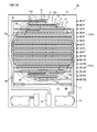
- FIG. 1 is a cross-sectional view showing a lighting device 1 in which a light emitting module 10 according to an embodiment is incorporated.
- the lighting device 1 is a downlight that is mounted so as to be embedded in the ceiling 2, and includes a fixture 3, a circuit unit 4, a dimming unit 5, and a lamp unit 6.
- the appliance 3 is made of metal and has a lamp housing portion 3a, a circuit housing portion 3b, and an outer casing portion 3c.
- the lamp housing portion 3a has a bottomed cylindrical shape, and the lamp unit 6 is detachably attached therein.
- the circuit housing part 3b extends on the bottom side of the lamp housing part 3a, and the circuit unit 4 is housed therein.
- the outer collar part 3c is annular and extends outward from the opening of the lamp housing part 3a.
- the appliance 3 has a lamp housing portion 3a and a circuit housing portion 3b embedded in an embedded hole 2a penetrating the ceiling 2, and an outer flange portion 3c that contacts the peripheral portion of the embedded hole 2a on the lower surface 2b of the ceiling 2. It is attached to the ceiling 2 in a contacted state.
- the circuit unit 4 incorporates a circuit for lighting the lamp unit 6. Further, the power supply line 4 a electrically connected to the lamp unit 6 is provided. A connector 4b detachably connected to the connector 72 of the lead wire 71 of the lamp unit 6 is attached to the tip of the power supply line 4a.
- the lamp unit 6 and the circuit unit 4 are separately unitized. However, a circuit corresponding to the circuit unit 4 may be built in the lamp unit.
- FIG. 2 is a perspective view of the lamp unit 6, and FIG. 3 is an exploded perspective view of the lamp unit 6.
- the lamp unit 6 includes the light emitting module 10 as a light source, and includes a base 80, a holder 30, a decorative cover 40, a cover 50, a cover pressing member 60, a wiring member 70, and the like.
- the base 80 has a disk shape made of aluminum die cast and has a mounting portion 81 in the center on the upper surface side.
- the light emitting module 10 is mounted on the mounting portion 81.
- screw holes 82 for screwing the assembly screws 35 for fixing the holder 30 are provided on both sides of the mounting portion 81.
- An insertion hole 83, a boss hole 84, and a notch 85 are provided in the peripheral portion of the base 80.
- the holder 30 has a bottomed cylindrical shape, and includes a disc-shaped presser plate portion 31 and a cylindrical peripheral wall portion 32 extending from the periphery of the presser plate portion 31 to the base 80 side.
- the light emitting module 10 is pressed against the mounting portion 81 by the pressing plate portion 31 and fixed to the base 80.
- a window hole 33 through which light from the light emitting module 10 passes is formed in the center of the pressing plate portion 31. Further, an opening 34 is formed in communication with the window hole 33 to prevent the lead wire 71 connected to the light emitting module 10 from interfering with the holder 30. Furthermore, an insertion hole 36 through which the assembly screw 35 is inserted is provided in a circumferential portion of the holding plate portion 31 of the holder 30 at a position corresponding to the screw hole 82 of the base 80.
- the light emitting module 10 is sandwiched between the base 80 and the holder 30 in a state where the sealing member 13 of the light emitting module 10 is exposed from the window hole 33 of the holder 30.
- the assembly screw 35 is inserted into the screw insertion hole 36 from above the holding plate portion 31 of the holder 30 and screwed into the screw hole 82 of the base 80, so that the holder 30 is attached to the base 80.
- the decorative cover 40 is an annular shape made of a non-translucent material such as a white opaque resin, and is disposed between the holder 30 and the cover 50, and the lead wire 71 and the assembly screw exposed from the opening 34 are provided. Covering 35 mag. A window hole 41 is also formed in the center of the decorative cover 40.
- the cover 50 is formed of a translucent material such as silicone resin, acrylic resin, glass, and the light emitted from the sealing member 13 passes through the cover 50 and is taken out of the lamp unit 6.
- the cover 50 has a dome shape, and includes a main body 51 having a lens function and an outer flange 52 extending outward from the peripheral edge of the main body 51, and the outer flange 52 is a base 80. It is fixed to.
- the cover pressing member 60 is made of a non-translucent material such as a metal such as aluminum or a white opaque resin, and has a circular plate shape so as not to block light emitted from the main body 51 of the cover 50. .
- the outer flange portion 52 of the cover 50 is sandwiched and fixed between the cover pressing member 60 and the base 80.
- a columnar boss portion 61 that protrudes toward the base 80 is provided on the lower surface side of the cover pressing member 60, and a semicircular cutout portion is formed on the outer flange portion 52 of the cover 50 at a position corresponding to the boss portion 61. 53 is formed. Further, a boss hole 84 through which the boss portion 61 is inserted is formed at a peripheral portion of the base 80 at a position corresponding to the boss portion 61.
- the boss portion 61 of the cover pressing member 60 is inserted into the boss hole 84 of the base 80, and the tip of the boss portion 61 is irradiated with laser light from below the base 80. Then, the tip portion is plastically deformed into a shape that does not come out of the boss hole 84. Thereby, the cover pressing member 60 is fixed to the base 80.
- Semicircular cutouts 54 and 62 are formed at positions corresponding to the insertion hole 83 of the base 80 on the outer peripheral portion 52 of the cover 50 and the cover pressing member 60, and are attached to be inserted into the insertion hole 83. Screws (not shown) are prevented from hitting the cover pressing member 60 and the cover 50.
- the wiring member 70 has a set of lead wires 71 electrically connected to the light emitting module 10.
- the lead wire 71 is led out of the lamp unit 6 through the notch 85 of the base 80, and a connector 72 is attached to the end thereof.
- FIG. 4 is a plan view illustrating an example of the light emitting module 10.
- the vertical direction of the paper surface is the vertical direction
- the horizontal direction of the paper surface is the horizontal direction.
- the light emitting module 10 includes a substrate 11, a plurality of light emitting elements 12 arranged on the substrate 11, a sealing member 13 covering the light emitting elements 12 for each row, terminal portions 14 and 15, wiring 16, 17 and the like.
- a plurality of light emitting elements 12 are two-dimensionally mounted on the mounting region 20 on the upper surface of the substrate 11. That is, in the mounting region 20, a plurality of light emitting elements 12 are arranged in a row in the horizontal direction to form a light emitting element row, and the plurality of light emitting element rows are arranged in parallel in the vertical direction.
- the mounting area is a light emitting area.
- the light emitting element rows from the first row to the 16th row are arranged in 16 rows at equal intervals in the vertical direction.
- column away from the center part up and down has few light emitting element 12 which comprises each light emitting element row
- the mounting area 20 is an area surrounded by a broken-line circle and has a circular shape.
- a total of 216 light emitting elements 12 are arranged.
- the diameter of the mounting area 20 is in the range of 20 mm to 50 mm.
- the substrate 11 has an insulating layer made of an insulating material such as ceramic or heat conductive resin.
- the whole substrate 11 may be an insulating layer, or may have a multilayer structure of an insulating layer and a metal layer made of an aluminum plate.
- the shape of the substrate 11 is not particularly limited, but here is a square plate.
- the light emitting element 12 is, for example, a GaN-based LED chip that emits blue light having a main wavelength of about 430 nm to 470 nm.
- the light emitting element 12 is mounted on the upper surface of the substrate 11 using COB (Chip on Board) technology.
- the size of the light emitting element 12 is, for example, 390 ⁇ m ⁇ 520 ⁇ m, 346 ⁇ m square, and the like.
- the light emitting element 12 is an LED and the light emitting module 10 is an LED module.
- the light emitting element 12 may be an LD (laser diode) or an EL element (electric luminescence element). good.
- Sealing member 13 For each light emitting element row, a line-shaped sealing member 13 extending in the lateral direction is provided so as to cover the plurality of light emitting elements 12.
- the sealing member 13 is formed of a translucent material mixed with a wavelength conversion material, and converts part of the light emitted from the light emitting element 12 into light of another wavelength.
- Each light emitting element 12 is sealed by a sealing member 13.
- Fluorescent particles can be used as the wavelength conversion material.
- a silicone resin for example, a fluorine resin, a silicone-epoxy hybrid resin, a urea resin, or the like can be used.
- Part of the blue light having a dominant wavelength of about 430 nm to 470 nm emitted from the light emitting element 12 is converted into light having a dominant wavelength of, for example, about 540 nm to 640 nm by the wavelength conversion material in the sealing member 13.
- white light is emitted by the color mixture of the converted wavelength band light and the unconverted blue light.
- the emission color of the phosphor used for the sealing member 13 may be changed to green or yellow for each light emitting element array.
- the color temperature of the entire white light can be adjusted in a range of about 2700 to 6500 ° C., for example.
- each light emitting element 12 can be improved by sealing with the line-shaped sealing member 13 for every light emitting element row
- Terminal, wiring, land The terminal portions 14 and 15 and the wirings 16 and 17 are conductor patterns formed on the insulating layer of the substrate 11.
- the terminal portions 14 and 15 are for supplying power to the light emitting element 12 and are formed on the peripheral edge of the upper surface of the substrate 11 as shown in FIG.
- the terminal portions 14 and 15 are electrically connected to the lead wire 71 shown in FIGS.
- bonding lands 19 are arranged at positions adjacent to the respective light emitting elements 12 on the substrate 11, and the respective light emitting elements 12 and the lands 19 are electrically connected by wire bonding.
- the light emitting elements 12 adjacent in the horizontal direction are directly connected by the lands 19.
- wirings 18a to 18d are arranged across adjacent light emitting element rows.
- FIG. 5 is a diagram showing the light emitting element blocks 21 to 32.
- the plurality of light emitting elements 12 mounted in the mounting area 20 are divided into 12 light emitting element blocks 21 to 32 by such wirings 18a to 18d and lands 19.
- each of the light emitting element blocks 21 to 32 is indicated by a thick line frame.
- 18 light emitting elements 12 are connected in series.
- the wiring 16 electrically connects one end portion of each light emitting element block 21 to 32 and the terminal portion 14.
- the wiring 17 electrically connects the other end portion of each light emitting element block 21 to 32 and the terminal portion 15.
- the light emitting element blocks 21 to 32 are connected to each other in parallel by wirings 16 and 17, and the entire light emitting elements 12 are connected in 18 lines and 12 lines in parallel.
- the light emitting elements 12 are electrically connected by wires through the lands 19, but the light emitting elements 12 can also be directly electrically connected by wires without using the lands 19. is there. In that case, the light emitting element 12 can be mounted on the substrate without being restricted by the position of the land 19. Further, no light absorption loss due to the land 19 occurs.
- Circuit unit 4 The circuit unit 4 is configured by a circuit including an AC / DC converter, and is electrically connected to an external commercial AC power supply (not shown), and power input from the commercial AC power supply is suitable for the element array of the light emitting elements 12. Converted to DC voltage and supplied. Thereby, all the light emitting elements 12 are controlled to be turned on collectively.
- the six light emitting element blocks 21 to 32 each including a plurality of (18) light emitting elements 12 connected in series are arranged side by side.
- the wirings 16 and 17 are connected in parallel.
- all of the light emitting elements 12 included in the light emitting element blocks 26 and 27 located in the center are blue light emitting elements 12B.
- the light emitting element blocks 21 to 25 located above the light emitting element blocks 26 and 27 and the light emitting element blocks 28 to 32 located below include not only the blue light emitting element 12B but also the red light emitting element 12R.
- the light emitting element blocks 26 and 27 belong to the first block group, and the other light emitting element blocks 21 to 25 and 28 to 32 belong to the second block group.
- the operating voltage of a light emitting element becomes higher as the emission wavelength becomes shorter. This is because the emission wavelength depends on the energy level of the light emitting layer constituting the light emitting element. For example, in the case of a blue light emitting element, the operating voltage is about 3V, and in the case of a red light emitting element, it is about 2V. That is, the red light emitting element 12R has a VF-IF characteristic in which an equivalent operating current flows even at a lower operating voltage as compared with the blue light emitting element 12B.
- the voltages applied to both ends of the light emitting element blocks 21 to 32 connected in parallel are equal.
- the number of light emitting elements in the light emitting element blocks 21 to 32 is the same.
- the operating currents of the light emitting element blocks 21 to 25 and 28 to 32 which are the second block group including the red light emitting element 12R whose operating voltage is lower than that of the blue light emitting element 12B are the light emitting element blocks which are the first block group. 26 and 27. That is, the more red light emitting elements 12R are included in the second block group, the greater the operating current of the second block group. This is because the operating current generally increases as the operating voltage of the light emitting element increases, or the operating voltage increases as the operating current increases.
- the power consumption of the first block group having a smaller operating current than that of the second block group is relatively small. Since the voltages applied to the first block group and the second block group are the same, the light emitting element block which is the first block group having a smaller operating current than the light emitting element blocks 21 to 25 and 28 to 32 which are the second block group The power consumption of 26 and 27 is relatively small.
- the light emitting element blocks 21 to 25, 27 and 27 are arranged so that the power consumption of the light emitting element blocks 26 and 27 is in the range of 85 to 97% of the average power consumption per light emitting element block.
- the number of red light emitting elements 12R mixed in 28 to 32 is set.
- the red light emitting elements 12R it is preferable to mount the red light emitting elements 12R at dispersed positions.
- the color rendering property is improved as compared with the case where only the blue light emitting element 12B is configured.
- Example comparative test
- Example is shown in FIG. Of the 216 light emitting elements 12, twelve red light emitting elements 12R are mounted, and the other light emitting elements 12 are all blue light emitting elements 12B.
- the element size (chip size) of each light emitting element 12 is constant.
- a light emitting module using the blue light emitting element 12B for all 216 light emitting elements was used.
- the embodiment is the same as the embodiment shown in FIG. 5 except that all are blue light emitting elements.
- the plurality of red light emitting elements 12 ⁇ / b> R are mounted in a point-symmetric manner (180 ° rotational symmetry) with respect to the center of the mounting area 20.
- the blue light emitting element 12B In the light emitting element blocks 26 and 27 located in the center, only the blue light emitting element 12B is mounted in series.
- the red light emitting elements 12R are also mixed. Specifically, in the light emitting element blocks 22, 25, 28 and 31, one red light emitting element 12R is mixed in one block, and in the light emitting element blocks 23, 24, 29 and 30, one block is included. In addition, two red light emitting elements 12R are mixed.
- FIG. 6A shows current VI-voltage VF characteristics of the red light emitting element 12R and the blue light emitting element 12B.
- the red light emitting element 12R has a VF-IF characteristic in which an equivalent operating current flows at a lower operating voltage than the blue light emitting element 12B.
- all the light emitting elements 12 are replaced with blue light emitting elements 12B.
- the power consumption in each light emitting element block is the same, and the temperature tends to rise in the central part where heat radiation is difficult.
- the voltage applied to each light emitting element block is 62V, and the average current flowing through each block is 50 mA.
- the voltage applied to each light emitting element 12B is 3.45V.
- the voltage applied to the red light emitting element 12R is 2.35V, and the voltage applied to each blue light emitting element 12B is 3.51V.
- the voltage applied to each red light emitting element 12R is 2.40V, and the voltage applied to each blue light emitting element 12B is 3.57V.
- each light-emitting element block The current flowing through each light-emitting element block, the power consumption, and the power consumption ratio are as shown in FIG.
- the power consumption ratio is a ratio of power consumption in each block based on the average value of power consumption per one block. For example, since the average value of power consumption is 3.1 W and the power consumption of the light emitting element block 21 is 2.7 W, the ratio when normalized is 87%.
- FIG. 7A is a graph showing power consumption for each light emitting element array (first to 16th examples).
- FIG. 7B is a graph showing the temperature distribution of each light emitting element array (first to 16th examples), and shows the temperature at the center in the horizontal direction of each light emitting element array.
- both the example and the comparative example tend to have a high temperature near the center, but in the comparative example, the temperature in the center is particularly high.
- the temperature rise in the central part is reduced. That is, in the comparative example, the temperature difference is large between the central portion and both sides of the mounting region, but in the embodiment, the temperature distribution is flattened.
- Warping of the substrate 11 is suppressed by flattening the temperature distribution.
- the substrate may cause damage or close contact with the instrument, resulting in a decrease in heat dissipation to the instrument.
- the temperature distribution in the example is flattened because, in the comparative example, the power consumption of each light emitting element block is equal, whereas in the example, the consumption of the first block group in the central portion is performed. It is considered that the power is smaller than the power consumption of the second block group.
- the substrate 11 since the substrate 11 includes a layer made of a ceramic material, the heat generated by the light emitting element 12 is not easily dispersed in the direction along the surface of the substrate 11. Generally, in such a case, heat is likely to be stored and the temperature is likely to be high, but in the light emitting module 10, an increase in temperature can be suppressed.
- the substrate 11 includes a layer made of a ceramic material like the light emitting module 10.
- the mounting density of the light emitting elements in the light emitting module is generally low (when the average area occupied by one light emitting element is smaller than 3.3 mm 2 / element). Is less likely to increase in temperature. On the other hand, it was also found that when the mounting density is high (when the average area occupied by one light emitting element is 3.3 mm 2 / element or less), the temperature rises easily.
- the temperature reduction effect obtained by the light emitting module 10 is large.
- the total number of light emitting elements 12 mounted in the mounting area 20 is also in the range of 40 to 520, the number of light emitting element arrays mounted in the mounting area 20 is 3 to 25, and the total input power is 10 W. If it is ⁇ 100 W, an excellent temperature reduction effect can be obtained.
- the number of the light emitting elements 12 arranged in each light emitting element row is smaller in the light emitting element row located at the end than the light emitting element row located in the center.
- the mounting area 20 was circular.
- the shape of the mounting region 20 is not particularly limited. For example, as shown below, when the mounting area 20 has a quadrangular shape, the same effect can be obtained.
- FIG. 8 is a diagram illustrating the light emitting module 100 in which the shape of the mounting region is a square shape.
- the light emitting module 100 has the same configuration as that of the light emitting module 10, but the mounting area 20 has a quadrangular shape.
- the same components as those of the light emitting module 10 are denoted by the same reference numerals.
- each light emitting element row corresponds to a light emitting element block, and each light emitting element block includes a plurality of (for example, 36) light emitting elements 12 connected in series.
- the eight light emitting element blocks 21 to 28 are connected in parallel to form a connection form of 36-by-8.
- the central light emitting element blocks 24 and 25 (belonging to the first block group), all blue light emitting elements 12G are used.
- the light emitting element blocks 21 to 23 and 26 to 28 (belonging to the second block group) located on both sides of the first block group are connected in series by mixing the blue light emitting element 12B and the red light emitting element 12R.
- the point that the power consumption per block of the first block group is set within the range of 85% to 97% with respect to the average power consumption is the same as described in the light emitting module 10.
- the power consumption of the light emitting element blocks 24 and 25 (first block group) in the center is reduced to the light emitting element blocks 21 to 23 and 26 to 28 (second block). Therefore, the temperature rise at the center of the mounting area can be reduced.
- the light emitting element block belonging to the first block group is configured by only the blue light emitting element 12B. However, even if the light emitting element block belonging to the first block group is mixed with the red light emitting element 12R. Good. In that case, the light emitting element blocks belonging to the second block group are mixed with more red light emitting elements 12R than the light emitting element blocks belonging to the first block group, thereby increasing the power consumption.
- the combination of light emission colors of the light emitting elements is not limited to blue and red. By using a combination of light emitting elements having different emission wavelengths and increasing the number of light emitting elements having a long emission wavelength in the light emitting element blocks belonging to the second block group, temperature rise can be similarly suppressed. Alternatively, a light emitting element that emits ultraviolet rays or infrared rays may be used. The light emission colors are not limited to two types, and light emitting elements of three or more colors can be used in combination.
- a light emitting element having a small size and a light emitting element having a small size are used. And in the 2nd block group in the both sides of a center part, compared with the light emitting element block of the 1st block group of a center part, the light emitting element block in which many large sized light emitting elements are mixed exists.
- the power consumption per block is smaller in the first block group in the center than in the second block group.
- the power consumption per light emitting element block in the first block group is within the range of 85% to 97% with respect to the average power consumption per light emitting element block in the whole.
- the temperature rise of the light emitting module 110 is reduced for the same reason as described in the first embodiment.
- FIG. 9A is a diagram illustrating an example of the light emitting module 110 and illustrates a mounting region in the light emitting module 110.
- the light emitting module 110 as in the light emitting module 100 shown in FIG. 8, eight light emitting element blocks 21 to 28 are connected in parallel. However, the number of light emitting elements 12 in each light emitting element block is 15 in series, and the connection form is 15 in series.
- the four light emitting elements indicated as “large size” in FIG. 9A are large size light emitting elements, and the other light emitting elements 12 are small size light emitting elements.
- the light emitting elements 12 In the central light emitting element blocks 24 and 25 (belonging to the first block group), all of the small size light emitting elements 12 are used. On the other hand, among the light emitting element blocks 21 to 23 and 26 to 28 (belonging to the second block group) located on both sides of the light emitting element blocks 21, 23, 26, and 28, the light emitting elements 12 of small size and large size are used. Are used in combination.
- the size of the small light emitting element 12 is 346 ⁇ m square, and the size of the large light emitting element 12 is 390 ⁇ m ⁇ 520 ⁇ m.
- FIG. 6B shows current VI-voltage VF characteristics of the large size light emitting element 12 and the small size light emitting element 12.
- the large-sized light emitting element 12 has a VF-IF characteristic in which the same operating current flows even at a low operating voltage, as compared with the small-sized light emitting element 12.
- each light emitting element block 21 to 28 Since the light emitting element blocks 21 to 28 are connected in parallel, the voltage applied to each light emitting element block is equal. The number of light emitting elements in each light emitting element block is the same in series.
- the operating current increases in a block including many large light emitting elements whose operating voltage is lower than that of a small light emitting element. That is, the more the large size light emitting elements are included, the greater the operating current of the block. This is because the operating current generally increases as the operating voltage of the light emitting element increases, or the operating voltage increases as the operating current increases. The power consumption of the light emitting element block including a large size light emitting element is also increased.
- the power consumption of the light emitting element blocks 24 and 26 (belonging to the first block group) composed of light emitting elements of only small size is the light emitting element blocks 21 to 23 and 26 to 28 (second block) including the large size light emitting elements. Relative to the group).
- the light emitting module 110 is driven at a voltage of 52.1 V, for example.
- the voltage applied to each light emitting element 12 is 3.49V.
- the voltage applied to the large light emitting element 12 is 2.88V, and the voltage applied to the small light emitting element 12 is 3.53V.
- the current flowing through each light emitting element block, the power consumption, and the power consumption ratio are as shown in FIG.
- the average current flowing through each block is 50 mA.
- the ratio (power consumption ratio) of the power consumption of the light emitting element blocks 24 and 25 located in the central part based on the average value of the power consumption per block as a whole is 94%.
- the temperature rise of the light emitting module 110 is reduced in the same manner as the light emitting module 100 described in the first embodiment.
- the light emitting element block belonging to the first block group is configured by only the small light emitting element 12, but the large light emitting element 12 is also mixed in the light emitting element block belonging to the first block group. May be.
- the light emitting element blocks belonging to the second block group include a larger number of light emitting elements 12 having a larger size than the light emitting element blocks belonging to the first block group, thereby increasing the power consumption.
- the power consumption per block is smaller in the first block group in the center than in the second block group on both sides.
- the power consumption per block in the first block group is defined within the range of 85% to 97% with respect to the average power consumption per block, as in the first and second embodiments. It is the same.
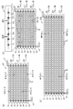
- FIG. 9B shows a mounting area of the light emitting module 120 according to the example.
- the light emitting module 120 is provided with light emitting element arrays (light emitting element blocks 21 to 28) having substantially the same length in the mounting area.
- Each of the light emitting element blocks 21 to 28 has a plurality (15) of light emitting elements 12 connected in series, and the eight light emitting element blocks 21 to 28 are connected in parallel to form a connection form of 15 in series. It has become.
- 15 light emitting elements 12 are connected in series, but with respect to some of the light emitting elements 12a.
- the light emitting elements 12b are connected in parallel.
- the light emitting elements 12b are connected in parallel to the four light emitting elements 12a.
- the light emitting element 12b is connected in parallel to the four light emitting elements 12a. Therefore, in the light emitting element blocks 22 and 27, the total number of light emitting elements in one block is 19.
- the light emitting element 12b is connected in parallel to the three light emitting elements 12a among the 15 light emitting elements 12. Therefore, in the light emitting element blocks 23 and 26, the total number of light emitting elements in one block is 18.
- the voltages applied across the light emitting element blocks 21 to 28 connected in parallel are equal.
- the number of series of each light emitting element block is the same 15. Since the current branches off at the place where the two light emitting elements are connected in parallel, the operating current per light emitting element is reduced compared to the place where only one element is connected in series and is connected in parallel. The operating voltage of the light emitting element is also lowered. Since the voltages applied to both ends of each light-emitting element block are equal, a light-emitting element block having more parts connected in parallel has more current flowing. That is, the light emitting element blocks 21, 24, 25, and 28 that do not include the parallel connection consume relatively less power than the light emitting element blocks 22, 23, 26, and 27 that include the parallel connection.
- the light emitting module 120 of the embodiment is driven by applying a voltage of 52.1V.
- the voltage applied to each light emitting element 12 is 3.48V.
- the light emitting element blocks 23 and 26 three light emitting elements 12a and 12b are connected in parallel.
- the voltage applied to the parallel connected parts is 3.26V
- the light emitting element 12 is applied to the single part.
- the voltage is 3.53V.
- four light emitting elements 12a and 12b are connected in parallel.
- the voltage applied when the light emitting elements 12 and 12b are connected in parallel is 3.27V
- the current, power consumption, and power consumption ratio flowing through the block in each light emitting element are the values shown in FIG.
- the average current flowing through each block is 50 mA.
- the light emitting element blocks 24 and 25 (first block group) at the center are the light emitting element blocks 22, 23, 26, and 27 (second block group). Compared to the above, less current flows per light emitting element block and power consumption is small. Accordingly, the temperature rise of the light emitting module 120 at the center is suppressed.
- the light emitting element block belonging to the first block group is configured by only the light emitting element 12 connected in series.
- the light emitting element 12b is also arranged in parallel with the light emitting element 12a in the light emitting element block belonging to the first block group.
- a connected location may be provided.
- the light emitting element block belonging to the second block group is mixed with more portions where the light emitting element 12b is connected in parallel to the light emitting element 12a than the light emitting element block belonging to the first block group, and the power consumption is reduced. Enlarge.
- the number of light emitting elements at the parallel connection location is not limited to two.
- the number of light emitting elements in the light emitting element block including the parallel connection portion may not be larger than the number of light emitting elements in the light emitting element block not including the parallel connection portion, and may be equal or less.
- the second block group includes light emitting element blocks having a larger number of series connections than the number of series connection of light emitting element blocks belonging to the first block group.
- the power consumption per block of the first block group is smaller than the power consumption per block of the second block group, as in the first to third embodiments.
- the temperature rise in the central portion can be suppressed.
- the power consumption per block in the first block group is set within the range of 85% to 97% with respect to the average power consumption per block. This is the same as in Embodiments 1 to 3.
- FIG. 9C shows a mounting area of the light emitting module 130 according to the example.
- the light emitting module 130 is provided with light emitting element arrays (light emitting element blocks 21 to 28) having substantially the same length in the mounting area.
- 36 light emitting elements 12 are connected in series to the light emitting element blocks 24 and 25 (first block group) in the center.
- 36 light emitting elements 12 are also connected in series in the light emitting element blocks 21 and 28.
- the second block group in the light emitting element blocks 22, 23, 26, and 27, as shown in FIG. The elements 12 are connected in series.
- the voltages applied across the light emitting element blocks 21 to 28 connected in parallel are equal.
- the operating voltage of each light emitting element 12 is increased.
- the power consumption of the light emitting element blocks 22, 24, 25, 27 composed of 36 light emitting elements is relatively smaller than that of the light emitting element blocks 21, 23, 26, 28 composed of 35 light emitting elements.
- the light emitting module 130 is driven at a voltage of 124.5V.
- the current flowing through each light emitting element block, the power consumption, and the power consumption ratio are the values shown in FIG.
- the average current flowing through the light emitting element block is 50 mA.
- the light emitting element blocks 24 and 25 (first block group) at the center are from the light emitting element blocks 21 to 23 and 26 to 28 of the second block group.
- the current flowing per light emitting element block is small and the power consumption is small. Therefore, the light emitting module 130 can suppress the temperature rise at the center.
- Embodiments 1 to 4 [Modifications of Embodiments 1 to 4] 1.
- the number of light emitting element blocks included in the first block group is two, and both of them have the same power consumption.
- the power consumption of the light emitting element blocks included in the first block group is as follows. They are not the same and may be different.
- the number of light emitting element blocks belonging to the first block group may be one, or may be three or more.
- only the light emitting element block 26 or only the light emitting element block 27 is set as the first block group, and the remaining light emitting element blocks are set as the second block group. It is good.
- the light emitting element blocks 25 to 27 or the light emitting element blocks 24 to 26 may be the first block group and the remaining light emitting element blocks may be the second block group. Further, the four blocks of the light emitting element blocks 25 to 28 may be the first block group, and the remaining light emitting element blocks may be the second block group.
- the eight light emitting element blocks 21 to 28 shown in FIG. 8 are provided, only the light emitting element block 24 or only the light emitting element block 25 may be the first block group and the remaining light emitting element blocks may be the second block group. . Further, the light emitting element blocks 23 to 25 or 24 to 26 are the first block group, and the remaining light emitting element blocks are the second block group. The four blocks of the light emitting element blocks 23 to 25 may be the first block group, and the remaining light emitting element blocks may be the second block group.
- the phosphor is mixed as a wavelength conversion material in the sealing material and the wavelength of light from the light emitting element is converted by the phosphor.
- the phosphor is not necessarily required.
- the first to fourth embodiments can be applied to a light emitting module in which LED chips of RGB three colors are mounted in combination.
- the power consumption of the light emitting element block which belongs to the 2nd block group can be made larger than the power consumption of the light emitting element block which belongs to the 1st block group, and the temperature rise of a center part can be reduced.
- Embodiments 1 to 4 the embodiment in which the light emitting element is directly mounted on the substrate has been described, but in addition to this, a so-called surface mount device (SMD) in which each light emitting element is primarily sealed is secondarily mounted on the substrate. It has also been confirmed that the same effect can be obtained when mounting.
- SMD surface mount device
- the light emitting module having a quadrangular mounting area is described as an example.
- the mounting area shown in FIG. 4 in the first embodiment can also be applied to a circular light emitting module.
- Embodiments 1 to 4 may be combined and implemented.
Landscapes
- Engineering & Computer Science (AREA)
- General Engineering & Computer Science (AREA)
- Physics & Mathematics (AREA)
- Microelectronics & Electronic Packaging (AREA)
- Optics & Photonics (AREA)
- Led Device Packages (AREA)
- Non-Portable Lighting Devices Or Systems Thereof (AREA)
- Arrangement Of Elements, Cooling, Sealing, Or The Like Of Lighting Devices (AREA)
Abstract
Description
本発明者は、基板上に、複数の発光素子が直列接続されてなる発光素子ブロックが、複数ブロック並べられて発光素子が2次元状に実装され、発光素子ブロック同士が並列に接続されてなる発光モジュールにおいて、温度上昇を低減する方法を検討した。
本発明の一態様にかかる発光モジュールは、基板上に、複数の発光素子が直列接続されている発光素子ブロックが複数ブロック並べられて発光素子が2次元状に配置され、発光素子ブロック同士が並列に接続されてなる発光モジュールにおいて、基板上に配置された複数の発光素子ブロックには、中央部に位置する第1ブロック群に属する発光素子ブロックと、第1ブロック群の両側に位置する第2ブロック群に属する発光素子ブロックとがあり、第2ブロック群には、第1ブロック群に属する発光素子ブロックの消費電力よりも消費電力の大きい発光素子ブロックが含まれるようにした。
[実施の形態1]
実施の形態1に係る発光モジュール、ランプユニットおよび照明装置について、図面を参照しながら説明する。
図1は、実施の形態に係る発光モジュール10が組み込まれた照明装置1を示す断面図である。
図2は、ランプユニット6の斜視図であり、図3は、ランプユニット6の分解斜視図である。
図4は、発光モジュール10の一例を示す平面図である。当図における紙面縦方向を縦方向、紙面横方向を横方向とする。
基板11は、セラミックあるいは熱伝導樹脂などの絶縁性材料からなる絶縁層を有している。基板11は、全体が絶縁層であってもよいし、絶縁層と、アルミ板からなる金属層の多層構造を有していてもよい。
発光素子12は、例えば、約430nm~470nmに主波長を有する青色光を出射するGaN系のLEDチップである。発光素子12は、基板11の上面にCOB(Chip on Board)技術を用いて実装されている。
各発光素子列ごとに、複数の発光素子12を覆うように、横方向に伸びるライン状の封止部材13が設けられている。この封止部材13は、波長変換材料が混入された透光性材料で形成され、発光素子12から出射される光の一部を、別の波長の光に変換する。また、各発光素子12は、封止部材13によって封止される。
端子部14,15および配線16,17は、基板11の絶縁層上に形成された導体パターンである。端子部14,15は、発光素子12への給電用であって、図4に示すように、基板11の上面周縁部に形成されている。この端子部14,15は、図1~3に示すリード線71と電気接続されている。
回路ユニット4は、AC/DCコンバータを備える回路で構成され、外部の商用交流電源(不図示)と電気的に接続され、商用交流電源から入力される電力を、発光素子12の素子列に適した直流電圧に変換して供給する。それによって、すべての発光素子12は一括して点灯制御される。
上記のように、実装領域20においては、複数(18個)の発光素子12が直列接続されてなる6つの発光素子ブロック21~32が並べて配置されており、発光素子ブロック21~32同士は、配線16,17によって並列に接続されている。
以下、実施例及び比較例に基づいて具体的に説明する。
実施例、比較例とも、総投入電力を37.2Wで共通にして、温度を計測した。
発光モジュール10の効果に関して、さらに以下の考察を行った。
図8は、実装領域の形状が四角状である発光モジュール100を示す図である。
実施の形態1においては、第1ブロック群に属する発光素子ブロックは、青色の発光素子12Bだけで構成したが、第1ブロック群に属する発光素子ブロックにも赤色の発光素子12Rを混在させてもよい。その場合、第2ブロック群に属する発光素子ブロックには、第1ブロック群に属する発光素子ブロックよりも、赤色の発光素子12Rを多く混在させて、その消費電力を大きくする。
本実施形態の発光モジュール110では、サイズの小さい発光素子とサイズの小さい発光素子とが用いられている。そして、中央部の両側にある第2ブロック群においては、中央部の第1ブロック群の発光素子ブロックと比べて、サイズの大きい発光素子が多く混在する発光素子ブロックが存在している。
図9(a)は、発光モジュール110の実施例を示す図であって、発光モジュール110における実装領域を示している。
実施の形態2においては、第1ブロック群に属する発光素子ブロックは、小サイズの発光素子12だけで構成したが、第1ブロック群に属する発光素子ブロックにも大サイズの発光素子12を混在させてもよい。その場合、第2ブロック群に属する発光素子ブロックには、第1ブロック群に属する発光素子ブロックよりも、大サイズの発光素子12を多く混在させて、その消費電力を大きくする。
本実施形態の発光モジュール120では、第2ブロック群に属する発光素子ブロックにおいて、直列接続された複数の発光素子12の一部に、並列に分岐する発光素子を付加している。並列に分岐する発光素子を付加した箇所では、より低電圧で同等の電流が流れるので、その発光素子ブロックの消費電力が大きくなる。
図9(b)に、実施例にかかる発光モジュール120の実装領域を示す。この発光モジュール120は、上記発光モジュール100と同様に、実装領域において、略同じ長さの発光素子列(発光素子ブロック21~28)が配設されている。
実施の形態3においては、第1ブロック群に属する発光素子ブロックは、直列接続した発光素子12だけで構成したが、第1ブロック群に属する発光素子ブロックにも発光素子12aに発光素子12bを並列接続させた箇所を設けてもよい。
本実施形態の発光モジュール130では、第1ブロック群に属する発光素子ブロックの直列接続数よりも、直列接続数の多い発光素子ブロックが第2ブロック群に含まれている。
図9(c)は、実施例にかかる発光モジュール130の実装領域を示す。
1.実施の形態1~4では、第1ブロック群に含まれる発光素子ブロックの数が2個で、その両者が同じ消費電力であったが、第1ブロック群に含まれる発光素子ブロックの消費電力は同一でなく、異なっていてもよい。
11 基板
12 発光素子
12B 青色の発光素子
12R 赤色の発光素子
12a,12b 発光素子
13 封止部材
14,15 端子部
16,17 配線
20 実装領域
21~32 発光素子ブロック
100 発光モジュール
110 発光モジュール
120 発光モジュール
130 発光モジュール
Claims (12)
- 基板上に、複数の半導体発光素子が直列接続されている発光素子ブロックが複数ブロック並べられて前記半導体素子が2次元状に配置され、前記発光素子ブロック同士が並列に接続されてなる発光モジュールにおいて、
前記基板上に配置された複数の発光素子ブロックは、
中央部に位置する第1ブロック群と、その両側に位置する第2ブロック群とに分けられ、
第2ブロック群には、第1ブロック群に属する発光素子ブロックの消費電力よりも消費電力の大きい発光素子ブロックが含まれる、
発光モジュール。 - 前記第1ブロック群に属する各発光素子ブロックの消費電力は、
発光モジュール全体における発光素子ブロックあたりの平均の消費電力に対して85%以上97%以下の範囲内である、
請求項1記載の発光モジュール。 - 前記基板上に配置されている半導体発光素子には、
第1半導体発光素子と、第1半導体発光素子よりも低い電圧で同等の電流が流れる電流-電圧特性を有する第2半導体発光素子とが含まれ、
第2ブロック群に属する消費電力の大きい発光素子ブロックは、
第1ブロック群に属する各発光素子ブロックと比べて多くの第2半導体発光素子を有する、
請求項1又は2記載の発光モジュール。 - 前記第1半導体発光素子の発光波長は前記第2半導体発光素子の発光波長よりも短波長である、
請求項3記載の発光モジュール。 - 前記第1半導体発光素子は青色を発光する素子であり、
前記第2半導体発光素子は赤色を発光する素子である、
請求項4記載の発光モジュール。 - 前記第2半導体発光素子は、第1半導体発光素子よりも素子サイズが大きい、
請求項3記載の発光モジュール。 - 前記第2ブロック群に属する消費電力の大きい発光素子ブロックにおいては、
直列接続されている複数の半導体発光素子の一部に、半導体発光素子が並列接続されて付加されている、
請求項1又は2記載の発光モジュール。 - 前記第2ブロック群に属する消費電力の大きい発光素子ブロックにおいては、
前記第1ブロック群に属する発光素子ブロックよりも、
半導体発光素子の直列接続数が少ない、
請求項1又は2記載の発光モジュール。 - すべての半導体発光素子が配置された領域に、前記半導体発光素子1個あたりが占める面積の平均は3.3mm2以下である、
請求項1~8のいずれかに記載の発光モジュール。 - 前記基板上に配置されている半導体発光素子の総数が40以上520以下である、
請求項1~9のいずれか記載の発光モジュール。 - 前記基板には、
セラミックス材料からなる層が含まれている、
請求項1~10のいずれかに記載の発光モジュール。 - 前記各発光素子ブロックに含まれる半導体発光素子同士は、
直接ワイヤボンディングによって電気接続されている、
請求項1~11のいずれか記載の発光モジュール。
Priority Applications (4)
| Application Number | Priority Date | Filing Date | Title |
|---|---|---|---|
| CN201380003616.8A CN103890488B (zh) | 2012-07-25 | 2013-05-23 | 发光模块 |
| EP13823905.8A EP2878883A4 (en) | 2012-07-25 | 2013-05-23 | LIGHT EMISSION MODULE |
| JP2014526732A JP6128465B2 (ja) | 2012-07-25 | 2013-05-23 | 発光モジュール |
| US14/351,957 US9416924B2 (en) | 2012-07-25 | 2013-05-23 | Light emission module |
Applications Claiming Priority (2)
| Application Number | Priority Date | Filing Date | Title |
|---|---|---|---|
| JP2012-164898 | 2012-07-25 | ||
| JP2012164898 | 2012-07-25 |
Publications (1)
| Publication Number | Publication Date |
|---|---|
| WO2014017005A1 true WO2014017005A1 (ja) | 2014-01-30 |
Family
ID=49996833
Family Applications (1)
| Application Number | Title | Priority Date | Filing Date |
|---|---|---|---|
| PCT/JP2013/003280 Ceased WO2014017005A1 (ja) | 2012-07-25 | 2013-05-23 | 発光モジュール |
Country Status (5)
| Country | Link |
|---|---|
| US (1) | US9416924B2 (ja) |
| EP (1) | EP2878883A4 (ja) |
| JP (1) | JP6128465B2 (ja) |
| CN (1) | CN103890488B (ja) |
| WO (1) | WO2014017005A1 (ja) |
Cited By (4)
| Publication number | Priority date | Publication date | Assignee | Title |
|---|---|---|---|---|
| CN104023452A (zh) * | 2014-06-23 | 2014-09-03 | 深圳市聚人成电子材料有限公司 | Cob光源驱动电路及驱动集成式cob光源 |
| US20150003057A1 (en) * | 2013-06-27 | 2015-01-01 | Genius Electronic Optical Co., Ltd. | High Heat Dissipation Lamp |
| JP2016021477A (ja) * | 2014-07-14 | 2016-02-04 | 豊田合成株式会社 | 発光装置 |
| JPWO2016158082A1 (ja) * | 2015-04-02 | 2017-12-21 | シャープ株式会社 | 発光装置 |
Families Citing this family (8)
| Publication number | Priority date | Publication date | Assignee | Title |
|---|---|---|---|---|
| DE102013203728A1 (de) * | 2013-03-05 | 2014-09-25 | Zumtobel Lighting Gmbh | LED-Modul und Beleuchtungsanordnung mit entsprechendem Modul |
| TWI507126B (zh) * | 2014-07-22 | 2015-11-11 | 玉晶光電股份有限公司 | 可調色之集魚燈具 |
| JP2016171129A (ja) * | 2015-03-11 | 2016-09-23 | パナソニックIpマネジメント株式会社 | 発光装置及び照明装置 |
| DE202015104835U1 (de) * | 2015-09-11 | 2016-12-14 | Zumtobel Lighting Gmbh | Betriebsgerät zur Versorgung einer Deckeneinbauleuchte |
| US10302863B2 (en) * | 2016-05-06 | 2019-05-28 | Ams Sensors Singapore Pte. Ltd. | Methods of attaching surfaces together by adhesives, and devices including surfaces attached together by adhesives |
| FR3061625B1 (fr) * | 2016-12-30 | 2020-07-24 | Commissariat Energie Atomique | Structure electronique comprenant une matrice de dispositifs electroniques presentant des performances thermiques ameliorees |
| JP2018206886A (ja) | 2017-06-01 | 2018-12-27 | パナソニックIpマネジメント株式会社 | 発光装置、及び、照明装置 |
| DE102017117540A1 (de) * | 2017-08-02 | 2019-02-07 | Osram Opto Semiconductors Gmbh | Lichtemittierender Halbleiterchip und Anzeigevorrichtung |
Citations (2)
| Publication number | Priority date | Publication date | Assignee | Title |
|---|---|---|---|---|
| JP2009004129A (ja) * | 2007-06-19 | 2009-01-08 | Sharp Corp | 基板及び照明装置 |
| JP2012009622A (ja) | 2010-06-24 | 2012-01-12 | Citizen Electronics Co Ltd | 半導体発光装置 |
Family Cites Families (20)
| Publication number | Priority date | Publication date | Assignee | Title |
|---|---|---|---|---|
| US7204607B2 (en) * | 2003-09-16 | 2007-04-17 | Matsushita Electric Industrial Co., Ltd. | LED lamp |
| JP4753904B2 (ja) * | 2007-03-15 | 2011-08-24 | シャープ株式会社 | 発光装置 |
| US7655954B2 (en) * | 2007-12-17 | 2010-02-02 | Ledtech Electronics Corp. | Array type light-emitting device with high color rendering index |
| KR101266226B1 (ko) * | 2008-07-09 | 2013-05-21 | 우시오덴키 가부시키가이샤 | 발광 장치 및 발광 장치의 제조 방법 |
| US8022641B2 (en) * | 2009-05-01 | 2011-09-20 | Focal Point, L.L.C. | Recessed LED down light |
| JP5431818B2 (ja) * | 2009-07-21 | 2014-03-05 | シチズン電子株式会社 | 発光ダイオード光源装置 |
| US8454195B2 (en) * | 2009-09-18 | 2013-06-04 | Luxingtek, Ltd. | Lighting device, lighting panel and circuit board thereof |
| CN102082141B (zh) * | 2009-11-26 | 2012-10-31 | 柏友照明科技股份有限公司 | 用于产生类圆形发光效果的多芯片发光二极管封装结构 |
| CN102261582A (zh) * | 2010-05-24 | 2011-11-30 | 台达电子工业股份有限公司 | 提高输出色彩显色性的单一封装发光二极管光源 |
| US20110309381A1 (en) * | 2010-06-21 | 2011-12-22 | Toshiba Lighting & Technology Corporation | Light-emitting device and lighting apparatus |
| CN102095093B (zh) * | 2010-11-16 | 2015-06-03 | 东莞市科磊得数码光电科技有限公司 | 一种新型的大功率led集成光源 |
| US20120287620A1 (en) * | 2011-05-10 | 2012-11-15 | Salvatore Guerrieri | LED Lighting |
| CN202049954U (zh) * | 2011-05-11 | 2011-11-23 | 柏友照明科技股份有限公司 | 发光模块 |
| TWM422032U (en) * | 2011-10-11 | 2012-02-01 | Paragon Sc Lighting Tech Co | LED lamp module |
| JP2013118292A (ja) * | 2011-12-02 | 2013-06-13 | Citizen Electronics Co Ltd | Led発光装置 |
| EP2658000B1 (en) | 2012-03-13 | 2018-05-02 | Panasonic Intellectual Property Management Co., Ltd. | Substrate, light-emitting device, and illumination device |
| JP2013201355A (ja) * | 2012-03-26 | 2013-10-03 | Toshiba Lighting & Technology Corp | 発光モジュール及び照明装置 |
| US9293662B2 (en) * | 2012-05-21 | 2016-03-22 | De L Associates Inc. | Light emitting device comprising chip-on-board package substrate and method for manufacturing |
| JP2013251144A (ja) * | 2012-05-31 | 2013-12-12 | Toshiba Lighting & Technology Corp | 発光モジュール及び照明装置 |
| JP6233750B2 (ja) * | 2014-03-14 | 2017-11-22 | パナソニックIpマネジメント株式会社 | 発光装置およびその製造方法、照明用光源、並びに照明装置 |
-
2013
- 2013-05-23 US US14/351,957 patent/US9416924B2/en not_active Expired - Fee Related
- 2013-05-23 JP JP2014526732A patent/JP6128465B2/ja active Active
- 2013-05-23 EP EP13823905.8A patent/EP2878883A4/en not_active Withdrawn
- 2013-05-23 CN CN201380003616.8A patent/CN103890488B/zh not_active Expired - Fee Related
- 2013-05-23 WO PCT/JP2013/003280 patent/WO2014017005A1/ja not_active Ceased
Patent Citations (2)
| Publication number | Priority date | Publication date | Assignee | Title |
|---|---|---|---|---|
| JP2009004129A (ja) * | 2007-06-19 | 2009-01-08 | Sharp Corp | 基板及び照明装置 |
| JP2012009622A (ja) | 2010-06-24 | 2012-01-12 | Citizen Electronics Co Ltd | 半導体発光装置 |
Non-Patent Citations (1)
| Title |
|---|
| See also references of EP2878883A4 |
Cited By (6)
| Publication number | Priority date | Publication date | Assignee | Title |
|---|---|---|---|---|
| US20150003057A1 (en) * | 2013-06-27 | 2015-01-01 | Genius Electronic Optical Co., Ltd. | High Heat Dissipation Lamp |
| US9279545B2 (en) * | 2013-06-27 | 2016-03-08 | Genius Electronic Optical Co., Ltd. | High heat dissipation lamp |
| CN104023452A (zh) * | 2014-06-23 | 2014-09-03 | 深圳市聚人成电子材料有限公司 | Cob光源驱动电路及驱动集成式cob光源 |
| JP2016021477A (ja) * | 2014-07-14 | 2016-02-04 | 豊田合成株式会社 | 発光装置 |
| JPWO2016158082A1 (ja) * | 2015-04-02 | 2017-12-21 | シャープ株式会社 | 発光装置 |
| US10205065B2 (en) | 2015-04-02 | 2019-02-12 | Sharp Kabushiki Kaisha | Light-emitting device |
Also Published As
| Publication number | Publication date |
|---|---|
| EP2878883A1 (en) | 2015-06-03 |
| CN103890488A (zh) | 2014-06-25 |
| US9416924B2 (en) | 2016-08-16 |
| US20140247597A1 (en) | 2014-09-04 |
| EP2878883A4 (en) | 2015-11-25 |
| CN103890488B (zh) | 2018-02-16 |
| JP6128465B2 (ja) | 2017-05-17 |
| JPWO2014017005A1 (ja) | 2016-07-07 |
Similar Documents
| Publication | Publication Date | Title |
|---|---|---|
| JP6128465B2 (ja) | 発光モジュール | |
| US8390021B2 (en) | Semiconductor light-emitting device, light-emitting module, and illumination device | |
| CN103311415B (zh) | 发光器件及使用其的照明装置和系统 | |
| JP5459623B2 (ja) | 照明装置 | |
| CN102483201A (zh) | 灯泡型灯 | |
| JP5545547B2 (ja) | 光源体および照明器具 | |
| WO2014091655A1 (ja) | 発光装置、照明用光源及び照明装置 | |
| US11107857B2 (en) | Light emitting diodes, components and related methods | |
| TW201340418A (zh) | 發光模組以及照明裝置 | |
| US9013097B2 (en) | Light-emitting module, lighting device, and lighting fixture | |
| JP2017163001A (ja) | 発光モジュール及び照明装置 | |
| CN102192424A (zh) | 发光装置以及照明装置 | |
| JP2004030929A (ja) | Led装置およびled照明装置 | |
| JP6008290B2 (ja) | 発光モジュール、照明装置および照明器具 | |
| JP5828100B2 (ja) | 発光装置及びそれを用いる照明装置 | |
| JP5838309B2 (ja) | 発光装置、照明用光源、および照明装置 | |
| JP2006080334A (ja) | Led発光装置 | |
| JP2015106502A (ja) | 照明装置 | |
| JP2014044814A (ja) | 発光モジュール装置、照明装置および発光装置 | |
| JP5453580B1 (ja) | 発光モジュール | |
| JPWO2014013671A1 (ja) | 電球形ランプ及び照明装置 | |
| JP2002158376A (ja) | 発光ダイオード照明装置 | |
| JP2016058650A (ja) | 発光装置、照明用光源、及び照明装置 | |
| WO2014030275A1 (ja) | 電球形ランプ及び照明装置 | |
| JP5417556B1 (ja) | 電球形ランプ及び照明装置 |
Legal Events
| Date | Code | Title | Description |
|---|---|---|---|
| 121 | Ep: the epo has been informed by wipo that ep was designated in this application |
Ref document number: 13823905 Country of ref document: EP Kind code of ref document: A1 |
|
| ENP | Entry into the national phase |
Ref document number: 2014526732 Country of ref document: JP Kind code of ref document: A |
|
| WWE | Wipo information: entry into national phase |
Ref document number: 2013823905 Country of ref document: EP |
|
| WWE | Wipo information: entry into national phase |
Ref document number: 14351957 Country of ref document: US |
|
| NENP | Non-entry into the national phase |
Ref country code: DE |