WO2014017103A1 - 電池保持ケース及びそれを収容する収容室を備えた電池包装体 - Google Patents
電池保持ケース及びそれを収容する収容室を備えた電池包装体 Download PDFInfo
- Publication number
- WO2014017103A1 WO2014017103A1 PCT/JP2013/004552 JP2013004552W WO2014017103A1 WO 2014017103 A1 WO2014017103 A1 WO 2014017103A1 JP 2013004552 W JP2013004552 W JP 2013004552W WO 2014017103 A1 WO2014017103 A1 WO 2014017103A1
- Authority
- WO
- WIPO (PCT)
- Prior art keywords
- battery
- holding case
- face
- holding
- flat
- Prior art date
- Legal status (The legal status is an assumption and is not a legal conclusion. Google has not performed a legal analysis and makes no representation as to the accuracy of the status listed.)
- Ceased
Links
Images


Classifications
-
- H—ELECTRICITY
- H01—ELECTRIC ELEMENTS
- H01M—PROCESSES OR MEANS, e.g. BATTERIES, FOR THE DIRECT CONVERSION OF CHEMICAL ENERGY INTO ELECTRICAL ENERGY
- H01M50/00—Constructional details or processes of manufacture of the non-active parts of electrochemical cells other than fuel cells, e.g. hybrid cells
- H01M50/10—Primary casings; Jackets or wrappings
- H01M50/102—Primary casings; Jackets or wrappings characterised by their shape or physical structure
- H01M50/109—Primary casings; Jackets or wrappings characterised by their shape or physical structure of button or coin shape
-
- H—ELECTRICITY
- H01—ELECTRIC ELEMENTS
- H01M—PROCESSES OR MEANS, e.g. BATTERIES, FOR THE DIRECT CONVERSION OF CHEMICAL ENERGY INTO ELECTRICAL ENERGY
- H01M10/00—Secondary cells; Manufacture thereof
- H01M10/05—Accumulators with non-aqueous electrolyte
- H01M10/058—Construction or manufacture
- H01M10/0585—Construction or manufacture of accumulators having only flat construction elements, i.e. flat positive electrodes, flat negative electrodes and flat separators
-
- H—ELECTRICITY
- H01—ELECTRIC ELEMENTS
- H01M—PROCESSES OR MEANS, e.g. BATTERIES, FOR THE DIRECT CONVERSION OF CHEMICAL ENERGY INTO ELECTRICAL ENERGY
- H01M50/00—Constructional details or processes of manufacture of the non-active parts of electrochemical cells other than fuel cells, e.g. hybrid cells
- H01M50/20—Mountings; Secondary casings or frames; Racks, modules or packs; Suspension devices; Shock absorbers; Transport or carrying devices; Holders
- H01M50/204—Racks, modules or packs for multiple batteries or multiple cells
- H01M50/207—Racks, modules or packs for multiple batteries or multiple cells characterised by their shape
- H01M50/216—Racks, modules or packs for multiple batteries or multiple cells characterised by their shape adapted for button or coin cells
-
- H—ELECTRICITY
- H01—ELECTRIC ELEMENTS
- H01M—PROCESSES OR MEANS, e.g. BATTERIES, FOR THE DIRECT CONVERSION OF CHEMICAL ENERGY INTO ELECTRICAL ENERGY
- H01M10/00—Secondary cells; Manufacture thereof
- H01M10/05—Accumulators with non-aqueous electrolyte
- H01M10/052—Li-accumulators
-
- Y—GENERAL TAGGING OF NEW TECHNOLOGICAL DEVELOPMENTS; GENERAL TAGGING OF CROSS-SECTIONAL TECHNOLOGIES SPANNING OVER SEVERAL SECTIONS OF THE IPC; TECHNICAL SUBJECTS COVERED BY FORMER USPC CROSS-REFERENCE ART COLLECTIONS [XRACs] AND DIGESTS
- Y02—TECHNOLOGIES OR APPLICATIONS FOR MITIGATION OR ADAPTATION AGAINST CLIMATE CHANGE
- Y02E—REDUCTION OF GREENHOUSE GAS [GHG] EMISSIONS, RELATED TO ENERGY GENERATION, TRANSMISSION OR DISTRIBUTION
- Y02E60/00—Enabling technologies; Technologies with a potential or indirect contribution to GHG emissions mitigation
- Y02E60/10—Energy storage using batteries
-
- Y—GENERAL TAGGING OF NEW TECHNOLOGICAL DEVELOPMENTS; GENERAL TAGGING OF CROSS-SECTIONAL TECHNOLOGIES SPANNING OVER SEVERAL SECTIONS OF THE IPC; TECHNICAL SUBJECTS COVERED BY FORMER USPC CROSS-REFERENCE ART COLLECTIONS [XRACs] AND DIGESTS
- Y02—TECHNOLOGIES OR APPLICATIONS FOR MITIGATION OR ADAPTATION AGAINST CLIMATE CHANGE
- Y02P—CLIMATE CHANGE MITIGATION TECHNOLOGIES IN THE PRODUCTION OR PROCESSING OF GOODS
- Y02P70/00—Climate change mitigation technologies in the production process for final industrial or consumer products
- Y02P70/50—Manufacturing or production processes characterised by the final manufactured product
Definitions
- the present invention relates to a battery holding case for holding a disk-shaped flat battery, and a battery package including a storage chamber for storing the battery holding case.
- Disc-shaped flat batteries such as coin batteries are small and thin, and may be accidentally swallowed by infants.
- electronic devices using a coin battery as a power source are provided with a lock mechanism in a storage room for storing coin batteries so that infants cannot easily remove the batteries, thereby preventing accidental ingestion.
- the exchanged coin batteries are discarded after being insulated, such as by attaching a resin tape so as not to short-circuit.
- the batteries may be bridged to form a circuit and short circuit.
- the capacity of the coin battery remains, there is a risk of heat generation, rupture or leakage due to a short circuit.
- JP 59-44762 A Japanese Utility Model Publication No.59-192262
- the outer dimensions of the coin battery are changed, so that the versatility of the coin battery is impaired and the range of electronic devices that can be used is limited.
- the present invention has been made in view of such points, and its main purpose is to prevent accidental ingestion of a disk-shaped flat battery and to significantly reduce damage to a living body even if accidentally ingested. It is an object of the present invention to provide a battery holding case that can prevent a short-circuit accident when collecting a holding case and, further, a disk-shaped flat battery.
- the battery holding case according to the present invention is a holding case for holding a disk-shaped flat battery, and the flat battery has a sealing plate that also serves as the first electrode surface and a battery case that also serves as the second electrode surface.
- the holding case has a sealed configuration via a ring-shaped gasket, and the holding case has a resin box shape having an open end face that can be inserted and removed from the electrode surface of the flat battery, and is formed on the side surface of the holding case. Is formed with a protrusion protruding radially inward from the peripheral edge on the opening end face side, and the protrusion is formed at a position separated from the bottom surface of the holding case by a distance larger than the thickness of the flat battery. .
- the side surface of the holding case is formed with a protruding portion that protrudes radially inward from the peripheral edge on the opening end surface side, so that the replaced battery is stored in the battery holding case.
- the battery package according to the present invention is housed in the battery package housing chamber in a state where the flat battery is held in the battery holding case.
- a user who has purchased a battery package distributed in the market in such a form takes out a battery holding case holding a flat battery from the battery packing body, and further takes out the battery from the battery holding case to be used as an electronic device. Installing. Therefore, even when the flat battery taken out from the battery package is left until it is mounted on the electronic device, the battery is held in the battery holding case, so that it is possible to prevent an infant from accidentally swallowing the battery. be able to.
- a holding case can be provided.
- FIG. 5A is a plan view
- FIG. 5B is a cross-sectional view taken along line BB in FIG. (A)-(c) is sectional drawing which showed the other step which hold
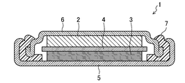
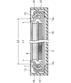
- FIG. 1 is a cross-sectional view schematically showing the configuration of a disk-shaped flat battery 1 according to the first embodiment of the present invention.
- the disk-shaped flat battery 1 refers to a battery having a thin disk shape such as a coin battery or a coin battery.
- the kind of battery is not ask
- the disk-shaped flat battery 1 is simply referred to as “battery”.
- the battery illustrated in FIG. 1 is a lithium battery.
- a negative electrode 2 using lithium or a lithium alloy as a negative electrode active material and a positive electrode 3 using graphite fluoride as a positive electrode active material are accommodated together with an electrolyte in a battery case 5 with a separator 4 interposed therebetween.
- the opening of the battery case 5 is sealed with a sealing plate 6 via a ring-shaped gasket 7.
- the positive electrode 3 contacts the bottom of the battery case 5, and the bottom surface of the battery case 5 also serves as the positive electrode surface.
- the negative electrode 2 contacts the sealing plate 6, and the upper surface of the sealing plate 6 also serves as the negative electrode surface.
- the outer diameter of the negative electrode surface 6 is smaller than the outer diameter of the positive electrode surface 5, and the negative electrode terminal forms a protruding electrode portion.
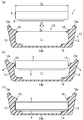
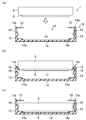
- FIGS. 2A to 2C are cross-sectional views showing steps of holding (accommodating) the battery 1 in a battery holding case (hereinafter simply referred to as “holding case”) 10.
- the battery 1 shows only the positive electrode surface 5 and the negative electrode surface 6.
- the holding case 10 includes a side surface portion 13 and a bottom surface portion 14 that hold the side surface or / and the bottom surface of the battery 1, and an open end surface that allows the battery 1 to be taken in and out of the electrode surface of the battery 1. And a resin box shape. Accordingly, the holding case 10 includes an opening 12 through which the battery 1 can be taken in and out, and a storage unit 11 in which the battery 1 is stored. Further, the side surface portion 13 of the holding case 10 is formed with a protruding portion 15 that protrudes radially inward from the peripheral edge portion on the opening end surface 13 a side. The protruding portion 15 extends from the bottom surface portion of the holding case 10 to the battery 1.
- the projecting portion 15 is formed in a ring shape, the inner diameter D 1 of the protrusion is smaller than the outer diameter D 2 of the battery. Further, the protruding portion 15 is integrally formed with the holding case 10. As shown in FIG. 2A, when the battery 1 is inserted into the storage portion 11 of the holding case 10 in the direction of the arrow, the peripheral portion of the positive electrode surface 5 of the battery 1 protrudes as shown in FIG. Hit 15.
- the holding case 10 is made of a deformable elastic member, as shown in FIG. 2B, as the battery 1 enters the storage portion 11 of the holding case 10, the side surface portion of the holding case 10 is obtained.
- the protruding portion 15 protruding radially inward from the peripheral edge portion on the opening end surface 13a side is formed on the side surface portion of the holding case 10, the replaced battery 1 is stored in the holding case 10. If it collects by doing so, the occurrence of a short circuit accident at the time of recovery can be prevented.
- the protruding portion 15 is formed at a position away from the bottom surface portion 14 of the holding case 10 by a distance larger than the thickness of the battery 1, the battery 1 is formed in the storage portion 11 of the holding case 10. It is housed on the bottom surface part 14 side. Therefore, the positive electrode surface 5 of the battery 1 is located away from the opening end surface 13 a of the holding case 10. Therefore, even if the holding cases 10 are stacked at the time of collection, it is possible to prevent occurrence of a short circuit accident due to contact between the batteries 1.
- an emetic may be applied to the outer surface of the side surface portion 13 and / or the bottom surface portion 14 of the holding case 10. Thereby, even if an infant accidentally includes the battery 1 in the mouth, the battery can be immediately discharged and swallowed into the body can be prevented. In addition, since the emetic is not given to battery 1 itself, when battery 1 is attached to an electronic device, no contact failure occurs.
- the resin material used for the holding case 10 is not limited, but as shown in FIG. 2B, the resin is so flexible that the side surface portion 13 is deformed while spreading outward. It is preferable that it is made of a material.
- the resin material of the holding case 10 for example, an omolefin elastomer resin having properties such as rubber can be used.
- a slit 30 is formed in the side surface portion 13 near the opening end surface 13a of the holding case 10 as shown in the perspective view of FIG. It is preferable.
- the shape, size, number, etc. of the slits 30 are not particularly limited.
- a plurality of slits 30 are formed at equal intervals along the ring-shaped opening end surface 13a. May be.
- the thin part 14b thinner than other parts.
- the negative electrode surface 6 of the battery 1 is housed in the holding case 10 toward the bottom surface portion 14 of the holding case 10.
- the positive electrode surface 5 of the battery 1 is stored. May be stored in the holding case 10 toward the bottom surface portion 14 of the holding case 10.
- the negative electrode surface 6 of the battery 1 is separated from the opening end surface 13 a of the holding case 10. In the position. Therefore, even if the holding cases 10 are stacked at the time of collection, it is possible to prevent occurrence of a short circuit accident due to contact between the batteries 1.
- the shape of the protrusion 15 in the present embodiment is not particularly limited, and may be formed in a ring shape, or may be formed with a plurality of protrusions 15 at equal intervals along the inner periphery of the side surface of the holding case 10. Good.
- FIG. 5 is a diagram showing a modification of the first embodiment of the present invention.
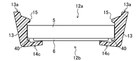
- an opening 12 b is provided in the bottom surface portion 14 of the holding case 10.
- the side surface portion 13 of the holding case 10 expands radially outward.
- the battery 1 is held in the storage portion 11 while being supported by the side surface portion 13 of the holding case 10.
- the battery 1 inserted into the storage portion 11 does not fall out of the opening portion 12b because the opening end portion 14c of the bottom surface portion 14 serves as a stopper.
- the opening end 14c is preferably inclined toward the storage unit 11 so that the opening end 14c contacts the negative electrode surface 6 (or the positive electrode surface 5) of the battery 1.
- the box shape of the holding case 10 is not particularly limited, and any shape can be used as long as it has an open end surface that can be taken in and out from the electrode surface of the battery 1 and a side surface portion.
- the outer shape may be a polygon as well as a circular shape in plan view.
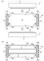
- 6 (a) and 6 (b) are diagrams showing another modification of the first embodiment of the present invention.
- the holding case 10 in this modification is provided with a first opening end surface 13a that can be taken in and out from the electrode surface of the battery 1, and on the opposite side of the first opening end surface 13a. It has a resinous box shape having a second opening end face 13b that can be taken in and out from one electrode surface.
- the holding case 10 has openings 12a and 12b through which the battery 1 can be taken in and out from two directions, and a storage part 11 in which the battery 1 is stored.
- the side surface portion 13 of the holding case has a first projecting portion 15a projecting radially inward from the peripheral portion on the first opening end surface 13a side, and a radially inner side from the peripheral portion on the second opening end surface 13b side.
- a second projecting portion 15 b is formed so that the distance between the first projecting portion 15 a and the second projecting portion 15 b is greater than the thickness of the battery 1.
- the side surface portion 13 of the holding case 10 faces outward in the radial direction.
- the battery 1 is held in the storage portion 11 while being supported by the side surface portion 13 of the holding case 10. Note that the battery 1 inserted into the storage portion 11 does not fall out of the opening 12b because the protruding portion 15b formed on the opening 12b side serves as a stopper. Thereby, the battery 1 is accommodated in the accommodating part 11 between the 1st protrusion part 15a and the 2nd protrusion part 15b.
- the side surface 13 of the holding case 10 is formed with protrusions 15a and 15b that protrude radially inward from the peripheral edge on the opening end surfaces 13a and 13b side.
- the box shape of the holding case 10 is not particularly limited, and any shape can be used as long as the holding case 10 has two opening end faces facing each other that can be taken in and out from the electrode surface of the battery 1 and side faces. It may be a thing.
- the outer shape may be a polygon as well as a circular shape in plan view.
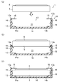
- FIG. 7A to 7C are cross-sectional views showing steps for holding the battery 1 in the holding case (resin case) 10 in the second embodiment of the present invention.
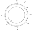
- FIG. 8 is a plan view of the holding case 10.
- the battery 1 shows only the positive electrode surface 5 and the negative electrode surface 6.
- the holding case 10 includes an opening 12 through which the battery 1 can be inserted and removed from the electrode surface of the battery 1, and a side surface 13 that holds the side surface and / or the bottom surface of the battery 1. And a bottom surface portion 14.
- the storage case 11 in which the battery 1 is stored is secured in the holding case 10.
- the holding case 10 has a ring-shaped projecting portion 15 projecting radially inward from the opening end surface 13 a of the side surface portion 13.
- the protrusion 15 is supported by the opening end surface 13a so as to be swingable.
- an emetic is applied to the outer surface of the side surface portion 13 and / or the bottom surface portion 14 of the holding case 10.
- a protrusion 16 that biases the side surface of the battery 1 is formed on the inner peripheral surface of the side surface portion 13 of the holding case 10.
- the shape of the projection part 16 is not specifically limited, For example, as shown in FIG. 8, you may provide four places at equal intervals along the circumferential direction of the side part 13 of the holding case 10.
- the bottom surface portion 14 of the holding case 10 is formed with a concave portion 14a in which a protruding electrode portion having the negative electrode surface 6 is embedded.
- the peripheral portion of the positive electrode surface 5 of the battery 1 is ring-shaped as shown in FIG. It hits the protruding part 15 of.
- the projecting portion 15 is made of a deformable elastic member, the projecting portion 15 is deformed as the battery 1 enters the storage portion 11 of the holding case 10 as shown in FIG.
- the protruding electrode portion having the negative electrode surface 6 is embedded in the concave portion 14 a formed in the bottom surface portion 14 of the holding case 10.
- the protrusion part 15 returns to the original position by the elasticity. In this state, the side surface of the battery 1 is held in the storage portion 11 by being biased by the protrusion 16 formed on the side surface portion 13 of the holding case 10.
- the emetic since the emetic is applied to the outer surface of the side surface portion 13 and / or the bottom surface portion 14 of the holding case 10 that holds the battery 1, an infant accidentally included the battery 1 in the mouth. Even in this case, the battery can be discharged immediately and swallowed by the body. In addition, since the emetic is not provided to the battery 1, when the battery 1 is mounted on an electronic device, no contact failure occurs.
- the protruding electrode portion having the negative electrode surface 6 is embedded in the recess 14 a formed in the bottom surface portion 14 of the holding case 10, the negative electrode surface 6 and the positive electrode surface 5 are connected to the bottom surface portion 14 of the holding case 10. By this, mutual insulation is ensured. Therefore, if the replaced battery 1 is stored in the holding case 10 and collected, a short circuit accident at the time of collection can be prevented.
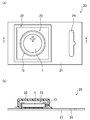
- FIG. 9 is a diagram schematically showing the configuration of the battery package 20 containing the flat battery 1 in the present embodiment
- FIG. 9A is a plan view
- FIG. 9B is FIG. 9A
- FIG. 6 is a sectional view taken along line BB of FIG.
- the battery package 20 includes a cover main body 22 in which a storage chamber 23 for storing the flat battery 1 is formed, and a base material for closing the storage chamber of the cover main body 22. And a blister pack composed of 21.
- the flat battery 1 is housed in the housing chamber 23 while being held in the holding case 10.
- a hole 24 for suspending the battery package 20 is formed in the base material 21.
- a user who has purchased the battery package 20 distributed in the market in such a form takes out the holding case 10 holding the battery 1 from the battery package 20, and further takes out the battery 1 from the holding case 10 to Attach to equipment. Therefore, even when the battery 1 taken out from the battery package 20 is left until it is mounted on the electronic device, the battery 1 is held in the holding case 10, so that an infant may accidentally swallow the battery 1. Can be prevented. Further, if the holding case 10 from which the battery 1 is taken out is left, the battery 1 is again stored in the holding case 10 and recovered, thereby preventing a short-circuit accident at the time of recovery.
- the battery 1 can be taken out of the holding case 10 against the urging force of the protrusion 16 by pushing the bottom surface portion 14 of the holding case 10 toward the battery 1.
- the concave portion 14a formed in the bottom surface portion 14 of the holding case 10 has a thin resin, the battery 1 can be easily taken out.
- the present invention can prevent a short circuit accident between the positive electrode surface 5 and the negative electrode surface 6 even in such a case.
- a description will be given with reference to FIGS. 10 (a) to 10 (c).
- FIG. 11 is an enlarged cross-sectional view of the holding case in the state shown in FIG.
- the battery 1 since the battery 1 is not embedded in the concave portion 14a formed in the bottom surface portion 14 of the holding case 10, the battery 1 has the concave portion 14a compared to the state shown in FIG. It approaches the protrusion 15 side by the depth, and is held in the storage unit 11.
- the radially inner end of the protrusion 15 is in contact with the negative electrode surface 6 of the battery 1, but covers the positive electrode surface 5 even if there is a slight gap without contact. As long as the short-circuit accident between the positive electrode surface 5 and the negative electrode surface 6 can be prevented.
- the material of the emetic applied to the outer surface of the side surface portion 13 and / or the bottom surface portion 14 of the holding case 10 is not particularly limited as long as it is a substance that feels a taste that a person puts into the mouth and exhales. .
- denatonium benzoate, chrysanthemum extract, yellowfin extract and the like can be used as a bitter substance.
- capsaicin, sinigrin, etc. can be used as a pungent substance.
- the emetic may be mixed in advance in the resin of the holding case 10.
- the material of the holding case 10 is not particularly limited.
- polypropylene (PP), polyethylene terephthalate (PET), or the like can be used.
- PP polypropylene
- PET polyethylene terephthalate
- the handling of the flat battery 1 or the like may be displayed on the bottom surface portion 14 of the holding case 10.
- safety precautions can be displayed.
- the flat battery 1 is accommodated in the accommodating chamber 23 of the battery package 20 such as a blister pack while being held in the holding case 10. And by giving the holding case 10 the accidental accident prevention function and the short circuit prevention function, the occurrence of accidental accidents and short circuit accidents is prevented.
- the holding case 10 can be formed with a very simple configuration, and the dimensions can be determined in accordance with the standard of the battery, so that it can be used as a highly versatile part. Therefore, it can be used not only for the battery package 20 but also as a holding case 10 for holding a battery.
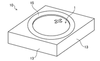
- FIG. 12 is a perspective view showing a modification of the holding case 10 in the present embodiment.
- the holding case 10 shown in FIG. 7A and FIG. 8 has a function of preventing accidental ingestion by applying an emetic to the outer surface of the side surface portion 13 and / or the bottom surface portion 14 of the holding case 10.
- the holding case 10 itself has a square outer shape to provide a function of preventing accidental ingestion.
- the opening end surface for taking in and out the battery 1 has a circular shape having substantially the same diameter as the positive electrode surface 5 of the battery 1, and the ring-shaped protruding portion 15 extends from the peripheral portion of the opening end surface. Projects radially inward.
- the side surface portion 13 of the holding case 10 has a quadrangular shape in plan view.
- the outer shape of the holding case 10 is not limited to a quadrangular shape in plan view, but may be a polygonal shape.
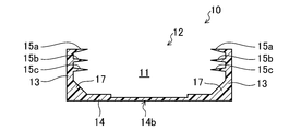
- FIG. 13 is a cross-sectional view showing another modification of the holding case 10 in the present embodiment.
- the holding case 10 has an opening 12 through which the battery 1 can be inserted and removed from the electrode surface of the battery 1, and a side surface 13 and a bottom surface 14 that hold the side surface or / and the bottom surface of the battery.
- three ring-shaped projecting portions 15a, 15b, and 15c are formed from the side surface portion 13 so as to project inward in the radial direction.
- Each projecting portion 15a, 15b, 15c is supported by the side surface portion 13 so as to be swingable, and the inner diameter of each projecting portion 15a, 15b, 15c is larger than the inner diameter of the exposed portion of the gasket (not shown). Is also getting smaller.
- a thin portion 14 b having a reduced thickness is formed at the center of the bottom surface portion 14.
- angular part of the side part 13 and the bottom face part 14 has the inclined surface 17 processed into the taper shape.
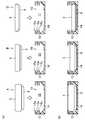
- 14 (a) and 14 (b) are cross-sectional views showing steps of holding (accommodating) three types of batteries A, B, and C having different thicknesses in the holding case 10, respectively.
- the protruding portion 15 a covers the positive electrode surface 5 of the battery A in a state where the thickest battery A is accommodated in the holding case 10.
- the other protrusions 15b and 15c hold the battery A by urging the side surface of the battery A in a deformed state. That is, in this modification, the protrusion 15a corresponds to the protrusion 15 shown in FIGS. 7A and 8, and the protrusions 15b and 15c correspond to the protrusions shown in FIGS. It corresponds to 16.
- the batteries B and C having a thickness smaller than that of the battery A are accommodated in the holding case 10, respectively, and the battery B is The positive electrode surface 5 of the battery B and the battery C is covered with the protrusion 15c.
- the positive electrode surface 5 of the battery 1 can be provided to the battery 1 having different thicknesses.
- Any one of the protrusions 15 can be covered. This is because the positive electrode surface 5 of the battery 1 can be covered with the protrusion 15 when the battery 1 is inserted into the holding case 10 from the positive electrode surface 5 as shown in FIGS. Therefore, it is particularly effective for preventing a short circuit accident when collecting the replaced battery 1.
- the thin part 14b in the bottom face part 14 of the holding case 10 the battery 1 accommodated in the holding case 10 can be easily taken out from the holding case 10 by pushing the thin part 14b. .
- the blister pack is described as an example of the battery package.
- the present invention is not limited to this, and for example, a pillow package made of a tubular packaging film may be used.
- the present invention is useful for a battery holding case that houses a flat battery used as a power source of an electronic device.
Landscapes
- Chemical & Material Sciences (AREA)
- Chemical Kinetics & Catalysis (AREA)
- Electrochemistry (AREA)
- General Chemical & Material Sciences (AREA)
- Engineering & Computer Science (AREA)
- Manufacturing & Machinery (AREA)
- Battery Mounting, Suspending (AREA)
- Sealing Battery Cases Or Jackets (AREA)
Abstract
Description
図1は、本発明の第1の実施形態における円盤状の扁平型電池1の構成を模式的に示した断面図である。ここで、円盤状の扁平型電池1は、コイン電池やコイン電池等の形状が薄型円盤状の電池をいう。また、電池の種類は問わず、例えば、一次電池であっても、二次電池であってもよい。以下、円盤状の扁平型電池1を単に「電池」という。なお、図1に例示した電池は、リチウム電池である。
図2(a)に示すように、電池1を矢印の方向に保持ケース10の収納部11に挿入すると、図2(b)に示すように、電池1の正極面5の周縁部が突出部15に当たる。ここで、保持ケース10を変形可能な弾性部材で構成しておけば、図2(b)に示すように、電池1が保持ケース10の収納部11に進入するに従い、保持ケース10の側面部13は、径方向外向に広がりながら変形する。そして、図2(c)に示すように、電池1が突出部15を通過した後、保持ケース10の側面部13は、その弾性により元の位置まで戻る。この状態で、電池1は、保持ケース10の側面部13に支持された状態で、収納部11内に保持される。
図7(a)~(c)は、本発明の第2の実施形態における電池1を保持ケース(樹脂ケース)10に保持するステップを示した断面図である。また、図8は、保持ケース10の平面図である。なお、電池1は、正極面5及び負極面6のみ表示している。
2 負極
3 正極
4 セパレータ
5 電池ケース(正極面)
6 封口板(負極面)
7 ガスケット
10 保持ケース
11 収納部
12、12a、12b 開口部
13 側面部
13a、13b 開口端面
14 底面部
14a 凹部
14b 薄肉部
15、15a、15b、15c 突出部
16 突起部
17 傾斜面
20 電池包装体
21 基材
22 カバー本体
23 収容室
24 孔
30 スリット
Claims (11)
- 円盤状の扁平型電池を保持する保持ケースであって、
前記扁平型電池は、第1の電極面を兼ねる封口板と第2の電極面を兼ねる電池ケースとがリング状のガスケットを介して密閉された構成をなし、
前記保持ケースは、前記扁平型電池の電極面から出し入れ可能な開口端面を有する、樹脂製の箱形形状をなしており、
前記保持ケースの側面部には、前記開口端面側の周縁部から径方向内側に突出する突出部が形成されており、
前記突出部は、前記保持ケースの底面部から、前記扁平型電池の厚みよりも大きい距離離れた位置に形成されている、電池保持ケース。 - 前記突出部は、リング状に形成されており、前記突出部の内径は、前記扁平型電池の外径よりも小さい、請求項1に記載の電池保持ケース。
- 前記保持ケースの開口端面近傍の側面部には、スリットが形成されている、請求項1に記載の電池保持ケース。
- 前記突出部は、前記保持ケースと一体成形されている、請求項1に記載の電池保持ケース。
- 前記保持ケースの底面部には、他の部位よりも厚みの薄い薄肉部が形成されている、請求項1に記載の電池保持ケース。
- 前記保持ケースは、前記扁平型電池の電極面から出し入れ可能な第1の開口端面と、該第1の開口端面と反対側であって、前記扁平型電池の電極面から出し入れ可能な第2の開口端面とを有する、樹脂製の箱形形状をなしており、
前記保持ケースの側面部には、前記第1の開口端面側の周縁部から径方向内側に突出する第1の突出部、及び前記第2の開口端面側の周縁部から径方向内側に突出する第2の突出部が形成されており、
第1の突出部15aと第2の突出部15bとの距離は、電池1の厚みよりも大きく形成されている、請求項1に記載の電池保持ケース。 - 前記保持ケースの側面部又は/及び底面部の外表面には、催吐剤が付与されている、請求項1に記載の電池保持ケース。
- 前記保持ケースの底面部の外表面には、前記扁平型電池の取り扱いが表示されている、請求項1に記載の電池保持ケース。
- 前記突出部は、前記保持ケースの開口端面側周縁部に揺動可能に支持されている、請求項2に記載の電池保持ケース。
- 前記突出部の内径は、前記ガスケットの露出部における内径よりも小さい、請求項1に記載の電池保持ケース。
- 請求項1~10の何れかに記載の電池保持ケースに保持された扁平型電池を収容する収容室を備えた電池包装体であって、
前記電池包装体は、
前記扁平型電池を収容する収容室が形成されたカバー本体と、
前記カバー本体の凹部を閉塞する基材と
で構成されたブリスターパックからなる、電池包装体。
Priority Applications (5)
| Application Number | Priority Date | Filing Date | Title |
|---|---|---|---|
| BR112015000661A BR112015000661A2 (pt) | 2012-07-27 | 2013-07-26 | invólucro de armazenamento de bateria para armazenar uma bateria chata em forma de disco, e embalagem de bateria |
| CN201380038175.5A CN104471741A (zh) | 2012-07-27 | 2013-07-26 | 电池保持壳体以及具有用于收纳该壳体的收纳室的电池包装体 |
| US14/416,540 US20150214514A1 (en) | 2012-07-27 | 2013-07-26 | Cell holding case and cell packaging body provided with housing chamber for housing same |
| IN136DEN2015 IN2015DN00136A (ja) | 2012-07-27 | 2013-07-26 | |
| EP13822950.5A EP2879200A1 (en) | 2012-07-27 | 2013-07-26 | Cell holding case and cell packaging body provided with housing chamber for housing same |
Applications Claiming Priority (2)
| Application Number | Priority Date | Filing Date | Title |
|---|---|---|---|
| JP2012166748A JP2014026848A (ja) | 2012-07-27 | 2012-07-27 | 電池包装体及びそれに使用される電池保持用樹脂ケース |
| JP2012-166748 | 2012-07-27 |
Publications (1)
| Publication Number | Publication Date |
|---|---|
| WO2014017103A1 true WO2014017103A1 (ja) | 2014-01-30 |
Family
ID=49995190
Family Applications (1)
| Application Number | Title | Priority Date | Filing Date |
|---|---|---|---|
| PCT/JP2013/004552 Ceased WO2014017103A1 (ja) | 2012-07-27 | 2013-07-26 | 電池保持ケース及びそれを収容する収容室を備えた電池包装体 |
Country Status (7)
| Country | Link |
|---|---|
| US (2) | US20140030570A1 (ja) |
| EP (1) | EP2879200A1 (ja) |
| JP (1) | JP2014026848A (ja) |
| CN (1) | CN104471741A (ja) |
| BR (1) | BR112015000661A2 (ja) |
| IN (1) | IN2015DN00136A (ja) |
| WO (1) | WO2014017103A1 (ja) |
Cited By (3)
| Publication number | Priority date | Publication date | Assignee | Title |
|---|---|---|---|---|
| US10700362B2 (en) | 2016-09-15 | 2020-06-30 | Energizer Brands, Llc | Coatings for mitigation of coin cell ingestion |
| CN113150711A (zh) * | 2020-01-23 | 2021-07-23 | 杜拉塞尔美国经营公司 | 用于暴露包括厌恶剂的安全特征的电池剥离组件 |
| WO2023047734A1 (ja) * | 2021-09-27 | 2023-03-30 | パナソニックIpマネジメント株式会社 | コイン形電池 |
Families Citing this family (13)
| Publication number | Priority date | Publication date | Assignee | Title |
|---|---|---|---|---|
| KR101621094B1 (ko) * | 2009-08-20 | 2016-05-16 | 삼성에스디아이 주식회사 | 이차 전지 |
| KR20140094898A (ko) * | 2013-01-23 | 2014-07-31 | 삼성에스디아이 주식회사 | 배터리 포장 케이스 |
| US9263716B2 (en) * | 2013-02-21 | 2016-02-16 | Lutron Electronics Co., Inc. | Monolithic battery holder having resilient retention strap for use in battery-powered sensor |
| US9741975B2 (en) | 2013-03-13 | 2017-08-22 | Brigham And Women's Hospital, Inc. | Safely ingestible batteries |
| JP6246483B2 (ja) * | 2013-04-04 | 2017-12-13 | 株式会社マキタ | 電動工具用電池パック |
| DE102015110243A1 (de) * | 2015-06-25 | 2016-12-29 | Schuler Pressen Gmbh | Batteriezellengehäuse, Träger und Verfahren zum Gruppieren mehrerer Batteriezellengehäuse |
| US11171375B2 (en) * | 2016-03-25 | 2021-11-09 | Enevate Corporation | Stepped electrochemical cells with folded sealed portion |
| JP7257568B2 (ja) * | 2016-10-03 | 2023-04-13 | 株式会社レゾナック・パッケージング | 蓄電デバイス用外装材 |
| IT201700075174A1 (it) * | 2017-07-05 | 2019-01-05 | Davide Brescianini | Elemento di copertura per polo di alternatore. |
| US10763486B2 (en) * | 2017-11-09 | 2020-09-01 | Duracell U.S. Operations, Inc. | Battery with safety mechanism |
| KR102930967B1 (ko) * | 2020-07-20 | 2026-02-25 | 주식회사 엘지에너지솔루션 | 이차전지용 트레이 및 그를 포함하는 트레이 조립체 |
| US20220069311A1 (en) | 2020-08-26 | 2022-03-03 | Fenwood Labs Inc. | Safely Ingestible Batteries that Rapidly Deactivate in Biological Environments and Methods of Making Same |
| US12595103B2 (en) | 2024-08-19 | 2026-04-07 | Energizer Brands, Llc | Blister package preventing colorant transfer |
Citations (7)
| Publication number | Priority date | Publication date | Assignee | Title |
|---|---|---|---|---|
| JPS5944762A (ja) | 1982-09-06 | 1984-03-13 | Matsushita Electric Ind Co Ltd | 小型電池 |
| JPS59192262U (ja) | 1983-06-08 | 1984-12-20 | 松下電器産業株式会社 | 角形電池 |
| JPS6225462U (ja) * | 1985-07-29 | 1987-02-16 | ||
| JPH04312762A (ja) * | 1991-04-11 | 1992-11-04 | Nitto Denko Corp | ボタン電池 |
| JP2004207147A (ja) * | 2002-12-26 | 2004-07-22 | Toshiba Battery Co Ltd | 電池用パッケージ |
| JP2008103261A (ja) * | 2006-10-20 | 2008-05-01 | Shin Etsu Polymer Co Ltd | 電池アダプタ |
| JP2011198599A (ja) * | 2010-03-19 | 2011-10-06 | Panasonic Corp | 電池ホルダ |
Family Cites Families (12)
| Publication number | Priority date | Publication date | Assignee | Title |
|---|---|---|---|---|
| GB1396862A (en) * | 1971-07-22 | 1975-06-11 | Suwa Seikosha Kk | Battery apparatus |
| JPS5922464A (ja) * | 1982-07-29 | 1984-02-04 | Fuji Xerox Co Ltd | タイミング同期回路 |
| JPS59226464A (ja) * | 1983-06-07 | 1984-12-19 | Matsushita Electric Ind Co Ltd | パツク形電池 |
| JPS6225462A (ja) * | 1985-07-25 | 1987-02-03 | Matsushita Electric Works Ltd | ジヤンクシヨン形電界効果トランジスタ |
| JPH042044A (ja) * | 1990-04-18 | 1992-01-07 | Sony Corp | ボタン型電池のホルダー |
| JP2973245B2 (ja) * | 1991-05-13 | 1999-11-08 | 松下電器産業株式会社 | 電子機器の電池収納装置 |
| JP2999719B2 (ja) * | 1996-06-25 | 2000-01-17 | 株式会社エーユーイー研究所 | 電池ホルダ |
| CA2285946C (en) * | 1998-02-05 | 2007-05-15 | Dai Nippon Printing Co., Ltd. | Sheet for cell case and cell device |
| JP2004348977A (ja) * | 2003-05-16 | 2004-12-09 | Matsushita Electric Ind Co Ltd | 電池用パッケージ |
| WO2007022563A1 (en) * | 2005-08-24 | 2007-03-01 | Graham Scott | Package with bitter taste aversive agent for infant deterrant |
| US20140170074A1 (en) * | 2010-09-21 | 2014-06-19 | Victoria Link Limited | Safety material and system |
| ES2527846T3 (es) * | 2011-12-22 | 2015-01-30 | Renata Ag | Envase blíster reutilizable para pilas de botón |
-
2012
- 2012-07-27 JP JP2012166748A patent/JP2014026848A/ja active Pending
- 2012-09-13 US US13/615,298 patent/US20140030570A1/en not_active Abandoned
-
2013
- 2013-07-26 BR BR112015000661A patent/BR112015000661A2/pt not_active IP Right Cessation
- 2013-07-26 CN CN201380038175.5A patent/CN104471741A/zh active Pending
- 2013-07-26 EP EP13822950.5A patent/EP2879200A1/en not_active Withdrawn
- 2013-07-26 IN IN136DEN2015 patent/IN2015DN00136A/en unknown
- 2013-07-26 WO PCT/JP2013/004552 patent/WO2014017103A1/ja not_active Ceased
- 2013-07-26 US US14/416,540 patent/US20150214514A1/en not_active Abandoned
Patent Citations (7)
| Publication number | Priority date | Publication date | Assignee | Title |
|---|---|---|---|---|
| JPS5944762A (ja) | 1982-09-06 | 1984-03-13 | Matsushita Electric Ind Co Ltd | 小型電池 |
| JPS59192262U (ja) | 1983-06-08 | 1984-12-20 | 松下電器産業株式会社 | 角形電池 |
| JPS6225462U (ja) * | 1985-07-29 | 1987-02-16 | ||
| JPH04312762A (ja) * | 1991-04-11 | 1992-11-04 | Nitto Denko Corp | ボタン電池 |
| JP2004207147A (ja) * | 2002-12-26 | 2004-07-22 | Toshiba Battery Co Ltd | 電池用パッケージ |
| JP2008103261A (ja) * | 2006-10-20 | 2008-05-01 | Shin Etsu Polymer Co Ltd | 電池アダプタ |
| JP2011198599A (ja) * | 2010-03-19 | 2011-10-06 | Panasonic Corp | 電池ホルダ |
Cited By (5)
| Publication number | Priority date | Publication date | Assignee | Title |
|---|---|---|---|---|
| US10700362B2 (en) | 2016-09-15 | 2020-06-30 | Energizer Brands, Llc | Coatings for mitigation of coin cell ingestion |
| CN113150711A (zh) * | 2020-01-23 | 2021-07-23 | 杜拉塞尔美国经营公司 | 用于暴露包括厌恶剂的安全特征的电池剥离组件 |
| WO2023047734A1 (ja) * | 2021-09-27 | 2023-03-30 | パナソニックIpマネジメント株式会社 | コイン形電池 |
| JPWO2023047734A1 (ja) * | 2021-09-27 | 2023-03-30 | ||
| JP7825194B2 (ja) | 2021-09-27 | 2026-03-06 | パナソニックIpマネジメント株式会社 | コイン形電池 |
Also Published As
| Publication number | Publication date |
|---|---|
| IN2015DN00136A (ja) | 2015-06-12 |
| JP2014026848A (ja) | 2014-02-06 |
| BR112015000661A2 (pt) | 2017-06-27 |
| US20140030570A1 (en) | 2014-01-30 |
| US20150214514A1 (en) | 2015-07-30 |
| EP2879200A1 (en) | 2015-06-03 |
| CN104471741A (zh) | 2015-03-25 |
Similar Documents
| Publication | Publication Date | Title |
|---|---|---|
| CN104471741A (zh) | 电池保持壳体以及具有用于收纳该壳体的收纳室的电池包装体 | |
| JP5838339B2 (ja) | 電池保持ケース及びそれを収容する収容室を備えた電池包装体 | |
| TWI431838B (zh) | 電池模組及電池組 | |
| US20190267685A1 (en) | Secondary Battery | |
| JP4402637B2 (ja) | 二次電池 | |
| JP3595346B2 (ja) | 保護フィルムを被覆した電池封口板及びそれを用いた電池 | |
| EP3570344A1 (en) | Secondary battery and top cover assembly thereof | |
| ES2971852T3 (es) | Conjunto de ventilación de seguridad para batería | |
| RU2308791C1 (ru) | Уплотняющая конструкция для литий-ионной полимерной батареи | |
| KR20160028749A (ko) | 이차전지 | |
| JP2019503058A (ja) | 二次電池および二次電池の電解液の補充方法 | |
| JP6455214B2 (ja) | 蓄電装置の保護方法及び蓄電装置 | |
| JP2015164111A (ja) | 蓄電装置 | |
| JP3187012U (ja) | 防爆型携帯電話 | |
| KR101828126B1 (ko) | 캡 조립체 | |
| CN103219482A (zh) | 电池 | |
| KR20180053404A (ko) | 전지용 스페이서 | |
| JP6547487B2 (ja) | 蓄電装置モジュール | |
| JP6191524B2 (ja) | 蓄電装置 | |
| JP3655821B2 (ja) | 電池パック及びこれを収容する電池収容室構造 | |
| JP2003257380A (ja) | 電 池 | |
| JPS6035171Y2 (ja) | アルカリ電池 | |
| CN104851991B (zh) | 电池及其制作方法 | |
| JP3160683U (ja) | リチウム電池 | |
| JP2000067841A (ja) | 密閉型電池ケース |
Legal Events
| Date | Code | Title | Description |
|---|---|---|---|
| 121 | Ep: the epo has been informed by wipo that ep was designated in this application |
Ref document number: 13822950 Country of ref document: EP Kind code of ref document: A1 |
|
| WWE | Wipo information: entry into national phase |
Ref document number: IDP00201500220 Country of ref document: ID |
|
| WWE | Wipo information: entry into national phase |
Ref document number: 2013822950 Country of ref document: EP |
|
| WWE | Wipo information: entry into national phase |
Ref document number: 14416540 Country of ref document: US |
|
| NENP | Non-entry into the national phase |
Ref country code: DE |
|
| REG | Reference to national code |
Ref country code: BR Ref legal event code: B01A Ref document number: 112015000661 Country of ref document: BR |
|
| ENP | Entry into the national phase |
Ref document number: 112015000661 Country of ref document: BR Kind code of ref document: A2 Effective date: 20150112 |